Rinnai America RWM101B Smart home gateway User Manual Rinnai PRD Rev 2 2x
Rinnai America Corporation Smart home gateway Rinnai PRD Rev 2 2x
User manual
(P
ROJECT
H
OTSPRING
)
P
RODUCT
R
EQUIREMENTS
D
EFINITION
(PRD)
Smart home gatewaySmart home gateway

2
of
21
Revision History
Rev. Author Change Description Date Status
1.0 Dipankar Sarkar Initial Draft 04/09/2015
Unreleased
1.1 Dipankar Sarkar Second Draft 04/09/2015
Unreleased
2.0 Dipankar Sarkar
Updated enclosure information in
section 6.1.1
Corrected section 6.5
Updated altitude and humidity
specifications in section 8.1
Corrected sections 3.1.2.3, 4.2 &
item-3 in section 9.2
Corrected section 10.1
04/27/2015
Unreleased
2.1 Wade Lindsey Multiple corrections 06/11/2015
Unreleased
2.2 Dipankar Sarkar
Added memory capacity information
in section 3.1.1
Added document number
Updated approver list in section 1.1
06/23/2015
Unreleased
Table 1 Revision History
3
of
21
TABLE OF CONTENTS
1.
DOCUMENTATION CONVENTIONS AND APPROVALS ........................................................................................................................... 5
1.1.
A
PPROVALS
................................................................................................................................................................................................. 5
1.2.
D
OCUMENTATION
C
ONTROL AND
R
EVISIONS
..................................................................................................................................................... 6
1.2.1.
The document will undergo revision for the following reasons: ................................................................................................... 6
1.2.2.
Document Revision Process: ......................................................................................................................................................... 6
1.3.
P
RODUCT
R
EQUIREMENT
C
ONVENTIONS
U
SED IN THIS
D
OCUMENT
....................................................................................................................... 6
1.4.
L
IST OF
A
PPLICABLE
D
OCUMENTS
.................................................................................................................................................................... 6
2.
SCOPE AND PURPOSE ......................................................................................................................................................................... 7
2.1.
G
LOSSARY OF
T
ERMS AND
A
CRONYMS
............................................................................................................................................................. 7
3.
TECHNICAL OVERVIEW .......... ................................................................................................................. 8
3.1.
M
AIN
PCB .................................................................................................................................................................................................. 8
3.1.1.
Processor and Memory ................................................................................................................................................................ 8
3.1.2.
Radios .......................................................................................................................................................................................... 8
4.
DETAILED PRODUCT SPECIFICATIONS .............................................. ...................................................... 9
4.1.
D
ESIGN
P
RACTICES
....................................................................................................................................................................................... 9
4.2.
P
OWER
S
UPPLY
............................................................................................................................................................................................ 9
4.3.
H
OST
P
ROCESSOR
C
HIPSET AND
M
EMORY
........................................................................................................................................................ 9
4.3.1.
Processor.................................................................................................................................................................................... 10
4.3.2.
Chipset DRAM ............................................................................................................................................................................ 10
4.3.3.
Chipset Flash .............................................................................................................................................................................. 10
4.4.
P
ROGRAMMING
......................................................................................................................................................................................... 10
4.5.
E
XTERNALLY
A
CCESSIBLE
C
ONNECTORS
,
S
WITCHES AND
I
NDICATORS
.................................................................................................................... 10
4.5.1.
2-wire terminal block ................................................................................................................................................................. 10
4.5.2.
LED Indicators ............................................................................................................................................................................ 10
4.5.3.
WPS Button ................................................................................................................................................................................ 10
4.5.4.
Reset Button .............................................................................................................................................................................. 11
5.
ANTENNA SYSTEM DESIGN AND RF PERFORMANCE ...........................................................................................................................11
5.1.1.
Simulation .................................................................................................................................................................................. 11
6.
MECHANICAL REQUIREMENTS ...........................................................................................................................................................11
6.1.
M
ECHANICAL
D
ESIGN
F
EATURES
................................................................................................................................................................... 11
6.1.1.
Enclosure .................................................................................................................................................................................... 11
6.1.2.
Chemical Resistance ................................................................................................................................................................... 14
6.1.3.
UV Stability ................................................................................................................................................................................ 14
6.2.
E
NCLOSURE
D
ESIGN
S
PECIFICATIONS
.............................................................................................................................................................. 14
6.3.
R
EAR
P
ANEL
D
ESIGN
S
PECIFICATIONS
............................................................................................................................................................. 14
6.4.
E
NCLOSURE
M
ECHANICAL
D
ESIGN
D
ETAILS
..................................................................................................................................................... 14
6.5.
T
HERMAL
S
PECIFICATIONS
........................................................................................................................................................................... 14
6.6.
L
ABEL
S
PECIFICATIONS
................................................................................................................................................................................ 15
6.7.
L
OGO
S
PECIFICATIONS
................................................................................................................................................................................. 15
6.8.
B
OARD
D
IMENSIONS
&
MOUNTING
[PR-026] ................................................................................................................................................. 15
7.
INDUSTRIAL DESIGN ..........................................................................................................................................................................15
8.
ENVIRONMENTAL SPECIFICATIONS AND PARAMETERS ......................................................................................................................15
8.1.
O
PERATIONAL
E
NVIRONMENTAL
E
NVELOPE
[PR-028] ...................................................................................................................................... 15
8.2.
N
ON
-
OPERATIONAL
E
NVIRONMENTAL
E
NVELOPE
[PR-029] ............................................................................................................................... 16
8.3.
V
ERTICAL
D
ROP
C
HASSIS
E
NDURANCE
[PR-030] ............................................................................................................................................. 16
8.4.
C
HASSIS
I
MPACT
[PR-031] ......................................................................................................................................................................... 16
8.5.
C
HASSIS
S
TATIC
L
OAD
[PR-032] .................................................................................................................................................................. 17
8.6.
S
HIPPING
V
IBRATION
[PR-033] ................................................................................................................................................................... 17
9.
SYSTEM PERFORMANCE METRICS AND RELIABILITY ...........................................................................................................................17
9.1.
L
ONG
-T
ERM
S
TABILITY
................................................................................................................................................................................ 17
..............................................
..............................................
4
of
21
9.2.
L
IST OF
C
RITICAL
C
OMPONENTS
.................................................................................................................................................................... 18
10.
AGENCY AND INDUSTRY CONFORMANCE REQUIREMENTS.................................................................................................................18
10.1.
S
AFETY
C
OMPLIANCE
............................................................................................................................................................................ 18
10.2.
S
YSTEM
I
MMUNITY
............................................................................................................................................................................... 18
10.3.
EMI
C
OMPLIANCE
................................................................................................................................................................................ 18
10.4.
R
O
HS
C
OMPLIANCE
.............................................................................................................................................................................. 19
11.
SUMMARY OF TECHNICAL HARDWARE SPECIFICATIONS ....................................................................................................................19
11.1.
U
NIT
A
RCHITECTURE
C
OMPLIANCE
M
ATRIX
............................................................................................................................................... 19
Statemtets.................................................................................................................................................................................................21
5
of
21
1. D
OCUMENTATION
C
ONVENTIONS AND
A
PPROVALS
1.1. A
PPROVALS
Prepared by Dipankar Sarkar _____________________________ Date: ____________
(Author)
Haedoo Choi _________________________________________ Date: ____________
Sr. Director, HVS Connectivity Product Management
Wade Lindsey _________________________________________ Date: ____________
Product Manager
Jonathan Scruggs _______________________________________ Date: ____________
Director, Program Management
Released Via ECO: _______________________________________ Date: ____________

6
of
21
1.2. D
OCUMENTATION
C
ONTROL AND
R
EVISIONS
1.2.1. T
HE DOCUMENT WILL UNDERGO REVISION FOR THE FOLLOWING REASONS
:
• Product architecture, specification, and / or feature changes
• New requirements added or deleted per customer request
• Technical corrections to the previous revision of the document
1.2.2. D
OCUMENT
R
EVISION
P
ROCESS
:
• Document revision number shall be changed per each new release
• After release, all revisions of this document and the revision history will be stored in the
PLM system
• All changes and new releases must be approved through the ECO process
1.3. P
RODUCT
R
EQUIREMENT
C
ONVENTIONS
U
SED IN THIS
D
OCUMENT
The requirements are classified into the following categories ideally:
• Mandatory - denoted by the words “Shall” or “Must” or “Will”
• Suggested – denoted by the word “Should”
• Optional – denoted by the word “May”
• Or Equivalent – requirements totally met by alternate solution
1.4. L
IST OF
A
PPLICABLE
D
OCUMENTS
The following is a partial list of documents datasheets are applicable to this specification:
IEEE 802.11: 2007
AMD 3 2008
06-Nov-2008
INFORMATION TECHNOLOGY - TELECOMMUNICATIONS
AND INFORMATION EXCHANGE BETWEEN SYSTEMS - LOCAL
AND METROPOLITAN AREA NETWORKS - SPECIFIC
REQUIREMENTS - PART 11: WIRELESS LAN MEDIUM ACCESS
CONTROL (MAC) AND PHYSICAL LAYER (PHY)
SPECIFICATIONS
IEEE 802.11n:
2009 AMD 5
29-Oct-2009 INFORMATION TECHNOLOGY - TELECOMMUNICATIONS
AND INFORMATION EXCHANGE BETWEEN SYSTEMS - LOCAL
AND METROPOLITAN AREA NETWORKS - SPECIFIC
REQUIREMENTS - PART 11: WIRELESS LAN MEDIUM ACCESS
CONTROL (MAC) AND PHYSICAL LAYER (PHY)
SPECIFICATIONS: AMENDMENT: ENHANCEMENTS FOR
HIGHER THROUGHPUT
FCC part 15:
2-16-06
16-Feb-2006 FCC part 15 - Federal Communications Commission
Regulations for Radio Frequency Devices
FCC Part 15.247
Rules for Radio Systems Using Digital Modulation
ZigBee Cluster Library
Specification
5/29/2012 Definition of the ZigBee Cluster Library
ZigBee Home
Automation Public
Application Profile
2/8/2010 Definition of the ZigBee Home Automation Profile
7
of
21
2. S
COPE AND
P
URPOSE
This document defines the product requirements specifications for a Smart home that gateway
enables user control and error status access of a Rinnai Tankless Water Heater through a WiFi based
cloud application.
The purpose of this document is to sufficiently define the product requirements so that the engineering
team can create the technical specifications for the specific product design. This specification is a higher
level document that defines specific features, functions, user experience, "look and feel" etc. Once this
document is approved, the specific design specifications will be written based on these requirements.
The detailed technical architecture of the product is not generally defined in this specification, unless it
is necessary from a product feature point of view.
Specific implementation details that are not covered by this document shall be at the discretion of the
PR engineering / management team, and should generally follow common industry practices, standards,
and procedures to insure a reliable product that meets the customer’s requirements. Many of the
specific implementation details will be defined in the technical specifications.
2.1. G
LOSSARY OF
T
ERMS AND
A
CRONYMS
The following abbreviations and acronyms are used throughout this document:
AP Wireless Access Point (may also have wired connections)
CMF Color, Materials, Finishes refers to the types of exterior appearances and textures the user
interfaces to; typically related to the plastics.
FR4 Epoxy printed circuit board material, meeting UL94V0 flammability requirements
GigE Giga Bit Ethernet
I2C Two wire interface used to transfer low speed data
IR Infrared
IML In-mold labeling is a technique used to add graphics to plastic parts
LED Light Emitting Diode
MII Media Independent Interface
NFF No Fault Found
PCB Printed Circuit Board
PSU System power supply
PMIC Power management integrated circuit
RTC Real Time Clock
SPI Serial Peripheral Interface (used to transfer medium speed data)
TFT Thin Film Transistor
UART Serial communications link (low speed) based on bidirectional TTL levels
USB Universal Serial Bus
WiFi Wireless technology used for data transfer in the 2.4GHz and 5.8GHz ISM bands
ZigBee Wireless technology used for mesh networking on the 2.4Ghz or 900MHz bands
8
of
21
3. T
ECHNICAL
O
VERVIEW
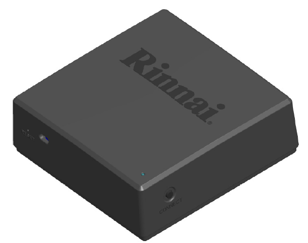
The Smart home gateway consists of the following major assemblies:
1. Main PCB
2. Enclosure (Housing)
3.1. M
AIN
PCB
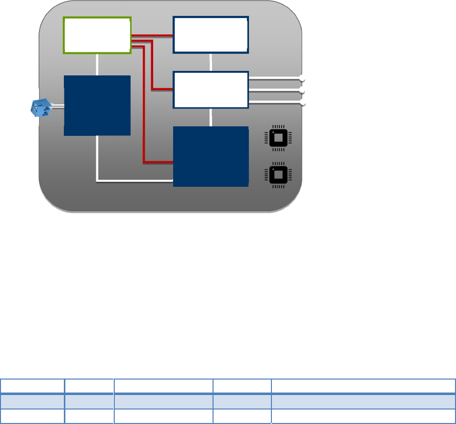
The main PCB is a multi-layer epoxy FR4 board (dimensions TBD) that contains all of the circuitry,
including WiFi and ZigBee radios. A functional description of each circuit block is provided in the
following sections. Refer to the following block diagram which defines each included circuit block.
Figure 1 Module Hardware Block Diagram
3.1.1. P
ROCESSOR AND
M
EMORY
The Host Processor shall be a MIPS24KEc embedded within the MediaTek MT7620A SoC [PR-001]. It will
support 256MB of DDR RAM and 256MB of NAND Flash.
3.1.2. R
ADIOS
The following radios will be used in the Smart home gateway: [PR-002]
Type Freq.
Vendors Interface
Comments
WiFi
2.4GHz
MediaTek
UART
MT7620A
ZigBee 2.4GHz
Silicon Labs
SPI
EM357
Table 2 Module Radio
Murata
H8D3317
DC Power
Section
ZigBee HA
1.2 SiLabs
Heater MCU
Renesas
R5F101JEDFA
Button 1
Button 2
GPIO
GPIO
UART
RGB LED
GPIO x 3
Linux WiFi SoC
MTK
SPI
9
of
21
3.1.2.1. W
I
F
I
M
ODULE
The WiFi module shall be an 802.11n module in 1x1 antenna configuration embedded within the
MediaTek MT7620A SoC [PR-003]
3.1.2.2. Z
IG
B
EE
/
R
ADIO
The ZigBee radio will utilize the Silicon Labs EM357 [PR-004]
3.1.3.
C
OMMUNICATION
P
ROPRIETARY
I
NTERCONNECT
The water heater communication interconnect uses a 2-wire physical interface which shall be using the
Murata H8D3317 custom IC. (See example schematic in Appendix-1)
3.1.4. P
OWER
C
ONNECTION
12 volt DC power for this module will be provided from the water heater on the two wires used for the
water heater communication (See example schematic in Appendix-1). Surge suppressors must be
incorporated on the input power lines for protection from conducted power surges.
3.1.5. H
OST
P
ROCESSOR
The Host Processor shall be a MIPS24KEc (580 MHz) with 64 KB I-Cache and 32 KB D-Cache embedded in
the MediaTek MT7620A SoC
3.1.6. A
PPLICATION
P
ROCESSOR
The Application Processor shall be the Renesas R5F101JEDFA
4. D
ETAILED
P
RODUCT
S
PECIFICATIONS
This section provides more detailed information for the Smart home gateway design.
4.1.
D
ESIGN
P
RACTICES
Industry standard design practices shall be used for this design consistent with a commercial consumer
product. [PR-005]
4.2. P
OWER
S
UPPLY
The Smart home gateway shall receive power via the power/interconnect cable connecting this
module with the water heater. The custom Murata chip (H8D3317) will be used to split the DC power
and the serial communications signals provided by the water heater over the power/interconnect
cable. The incoming DC power shall be appropriately regulated in the DC Power section for use by this
module. [PR-006]
4.3. H
OST
P
ROCESSOR
C
HIPSET AND
M
EMORY
The description of the host processor and associated memory is defined in the following
subsections.

10
of
21
4.3.1. P
ROCESSOR
The processor shall be the MIPS24KEc operating at a clock speed of 580MHz, embedded in the
MediaTek chipset. This processor has 64 KB I-Cache and 32 KB D-Cache. In addition this
processor supports multiple IO interfaces, including GPIO, I2C, I2S, SPI, PCM, UART, etc. [PR-007]
4.3.2. C
HIPSET
DRAM
The Smart home gateway shall be designed to support 256MB of 16-bit DDR-2 memory,
which must be compatible for operation with the host processor. Final production boards may
use 64MB or 128MB of DDR-2 memory if the software image is compatible with the smaller
memory size. [PR-008]
4.3.3. C
HIPSET
F
LASH
The Smart home gateway design will incorporate 128MB of NAND Flash to maintain the
code image and bootloader. [PR-009]
4.4. P
ROGRAMMING
The main board shall include the capacity to download code into any programmable parts.
Headers for JTAG, UART, and/or equivalent shall be included for this purpose. Programming
headers may or may not be populated for production. [PR-010]
4.5. E
XTERNALLY
A
CCESSIBLE
C
ONNECTORS
,
S
WITCHES AND
I
NDICATORS
The Smart home gateway must provide a terminal block for a 2-wire connection.
The Module must provide the following external accessible switches and indicators: [PR-011]
1. 1 Tri-color status indicator LED
2. WiFi Configuration button
3. System Reset button
4.5.1. 2-
WIRE TERMINAL BLOCK
The 2-wire terminal block will be used for power/communication connection to the water heater.
4.5.2. LED
I
NDICATORS
The Tri-color LED indicator will be used to designate the following functions: [PR-012]
Color Function Description
Red
Error condition
Error condition
Blue Connected Blinking = WiFi connection; Solid = Internet connection
Green Pairing mode active
Pairing mode active
Table 3 LED definitions
4.5.3. W
I
F
I
C
ONFIGURATION
B
UTTON
The App Enablement Module shall incorporate a GPIO-connected WiFi Configuration button to assist the
user in the wireless set-up process. [PR-013]
TheSmart home gateway shall incorporate a GPIO-
11
of
21
4.5.4. S
YSTEM
R
ESET
B
UTTON
The Module shall provide a RESET button connected to the system reset lines for the MediaTek, Silicon
Labs and Renesas SoCs to reset all application processes. [PR-014]
5. A
NTENNA
S
YSTEM
D
ESIGN AND
RF
P
ERFORMANCE
Since the Smart home gateway contains two 2.4GHz radios, coexistence between the radios is a
critical performance issue. Most of the coexistence issues are due to the antenna design. For this
reason, commercially available chip antennas shall be utilized, with suitable placement/positioning to
maximize antenna isolation. A full simulation and analysis must be done to optimize the design and
placement of the antennas to provide optimum performance and reduce degradation due to insufficient
antenna isolation. [PR-015]
5.1.1. S
IMULATION
As part of the design process, each of the proposed antenna placements shall be simulated, and
modified as required to optimize the performance of the system. The simulation shall measure the
radiation pattern and isolation of each antenna. If design changes are necessary, this specification will
be revised. The simulation must also calculate the in-band and the out-of-band energy into each
receiver, to ensure that the maximum input levels (as specified by the transceiver manufacturer) are not
exceeded (exceeding the maximum input can result in receiver damage). It shall be up to the discretion
of the design team to include band pass filters into the design to protect the receivers from excessive
input level. [PR-016]
6. M
ECHANICAL
R
EQUIREMENTS
The industrial and mechanical design of theSmart home gateway will be developed in conjunction
with the ME team, to optimize aesthetics, cost and manufacturability. The design will follow the Rinnai
guidelines and requirements. Specific mechanical design features and attributes are the decision of the
implementation team, but the final design must be reviewed and approved by the customer.
6.1. M
ECHANICAL
D
ESIGN
F
EATURES
The mechanical design shall consist of:
6.1.1. E
NCLOSURE
The Smart home gateway enclosure shall consist of a base and a cover made of injection molded
plastic (ABS or PC-ABS).
The Industrial Design shall adhere to the following enclosure concept design examples and guidelines
shown below.
12
of
21
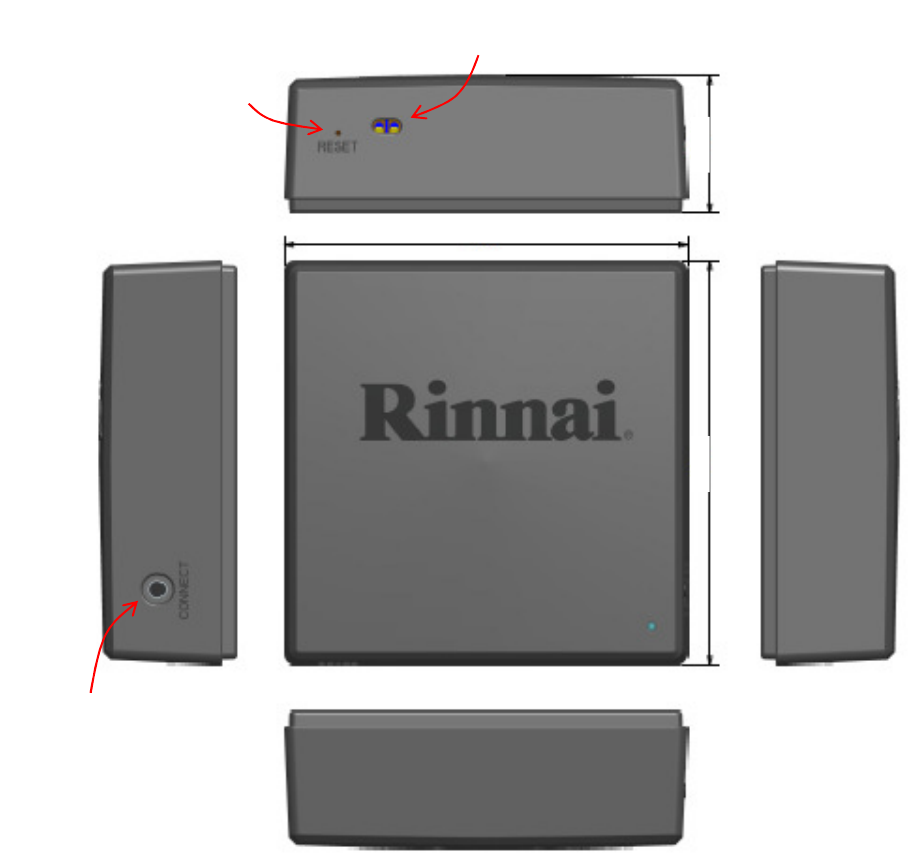
The unit is expected to be mounted on the wall or on the water heater. The base of the unit shall
incorporate keyhole slots and magnets for ease of mounting. [PR-017]
93.6mm
93.6mm
93.6mm
93.6mm
Screw Terminal Block: Input for 12VDC
Power & Serial Communication
Reset Button
WiFi Provisioning
Button
13
of
21
The design should accommodate the fact that the unit is expected to be mounted on a wall or on a large
metal plate (the water heater), which will cause near-field obstruction. The PCBA mounting should
increase the distance between the antenna and any near-field obstruction, to improve the performance
of the antenna(s).
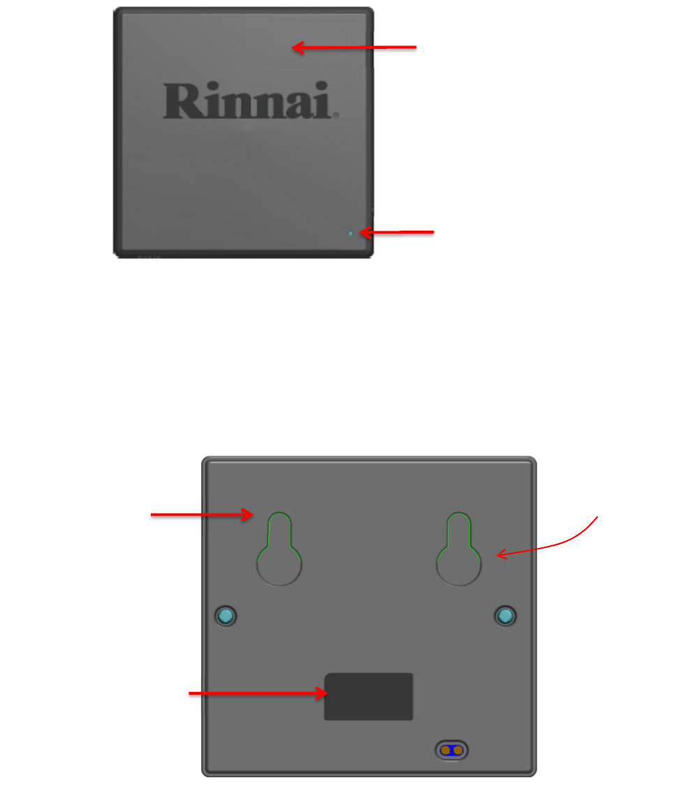
Front Cover
Material: ABS
Color: Black
MT11010 &
high Polished
on logo
LED lens
Material: PMMA
Color:
Transparent
Polished
Material:
ABS
Color: Black
MT11015
Product label
Material: Paper
Color: black
Fog treatment
in surface
Keyhole Feature
for Wall Mount
14
of
21
6.1.2. C
HEMICAL
R
ESISTANCE
The mechanical design shall demonstrate chemical resistance to short-term exposure to common
household cleaning agents applied to the exterior of the product, as well as any substance commonly
found on the human hand. [PR-018]
6.1.3. UV
S
TABILITY
UV resistance per ASTM 4674 Method 1: Delta E<1.4: Irradiance level of 2806 W-h/m2. No degradation
of the material is allowed, but color changes are acceptable. In the event of a color change, the change
shall result in a delta-E of 1.4 or less for HB for ABS material or 1.7 or less for PC material. [PR-019]
6.2. E
NCLOSURE
D
ESIGN
S
PECIFICATIONS
The enclosure is a simple box structure consisting of a rear panel or base and a top or front
cover with front face and side walls.
The front face shall accommodate the Rinnai logo, as shown in the example ID, and the status
LED as defined in section # 4.5.2 [PR-020]
The top cover shall have holes/cutouts, as shown in the example ID, to accommodate the
terminal block and the two buttons (Reset & WPS) defined in section # 4.5
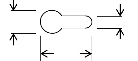
6.3. R
EAR
P
ANEL
D
ESIGN
S
PECIFICATIONS
The rear panel shall be designed with two key-hole slots for wall mounting, according to the
keyhole dimensions shown below. The depth of the slot shall be 5mm and shall accommodate a
screw head thickness of 3mm. The plastic design shall block direct access into the enclosure
through the keyhole slot.
The rear panel design shall also have design features to install one or more magnets, to enable
the unit to be magnetically mounted on the water heater. [PR-021]
6.4. E
NCLOSURE
M
ECHANICAL
D
ESIGN
D
ETAILS
The maximum enclosure dimensions and approximate weight shall be: [PR-022]
• Width: 100 mm MAX
• Length : 100 mm MAX
• Thickness: 35 mm MAX
• Weight: TBD lbs. MAX
Note: all dimensions are approximate
6.5. T
HERMAL
S
PECIFICATIONS
The operating and storage temperature ranges shall be: [PR-023]
8mm 4mm
14mm
15
of
21
• The Smart home gatewayshall be designed to operate without any performance
degradation throughout the temperature range of the device. (0 to 40 deg. C)
• Storage temperature shall be -10 to +60 deg. C
6.6. L
ABEL
S
PECIFICATIONS
The mechanical design shall provide labeling areas as follows: [PR-024]
• Product identification
o Serial Number
o MAC Address
o Ayla DSN
• Warnings
o “Class-2 Low Voltage connection only”
• Agency-required labels
o FCC
o IC
7. I
NDUSTRIAL
D
ESIGN
The industrial design of the S mart home gateway(ID) shall follow the example provided in
section # 6.1.1 [PR-027]
8. E
NVIRONMENTAL
S
PECIFICATIONS AND
P
ARAMETERS
This section describes the operational and non-operational environment the Smart home gateway
shall be designed to operate in. For the purposes of this section, the following
definitions apply:
• Functional failure: Permanent loss of functionality or degradation in performance below
specified limits, not including cosmetic failures.
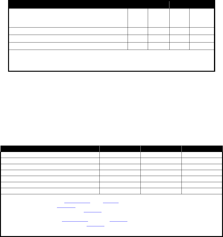
8.1. O
PERATIONAL
E
NVIRONMENTAL
E
NVELOPE
[PR-028]
Table 4 - Operational Environmental Envelope
16
of
21
Parameter Min Typical Max Unit
Operating Temperature
@ sea level
1
@ max altitude
0
40
35
⁰C
Operating Humidity
2
8 95 %RH
Operating Altitude, relative to Mean Sea Level (MSL) 3100 M
Operational Temperature Ramp 20 ⁰C/hr
Notes:
1. Sea-level testing is performed at a nominal altitude of 0-300 m.
2. Non-condensing.
Table 5 Operational Environment Envelope
8.2. N
ON
-
OPERATIONAL
E
NVIRONMENTAL
E
NVELOPE
[PR-029]
These specifications cover the product after it has been removed from its retail packaging.
Table 6 - Storage Environment Specifications
Parameter Min Max Unit
Temperature (External ambient)
1
-10 60 °C
Temperature Ramp Rate
2
10 °C/minute
Relative Humidity
3, 8
5 95 %
Relative Humidity Ramp Rate
4
30 %/hour
Wet-Bulb Temperature
5
40 °C
Altitude, relative to Mean Sea Level (MSL)
6
-382 (106) 13600 (15.0) m (kPa)
Pressure Ramp Rate
7
10 kPa/minute
Notes:
1. These limits were derived from ETSI 300 019-2-7, T7.3 & SAE J1455.
2. This limit comes from ESTI 300 019-2-7, T7.3.
3. This limit comes from guidance found in IEC 60068-2-30 & previous testing experience.
4. This limit comes from information gathered in other electronic devices’ specifications.
5. This specification comes from ETSI 300 019-2-7, T7.3 and IEC 60068-2-13.
6. This limit is based upon guidance found in IEC 60068-2-13.
Condensation is not permitted under any circumstances.
Table 7 Non-Operational Environment Envelope
8.3. V
ERTICAL
D
ROP
C
HASSIS
E
NDURANCE
[PR-030]
The Smart home gateway MUST be operational within specifications after being dropped
once on any side without its shipping carton from a height of 75 cm onto a concrete floor.
The Smart home gateway MUST NOT develop any openings or other deformations that
could introduce the risk of an electrical shock.
8.4. C
HASSIS
I
MPACT
[PR-031]
17
of
21
The Smart home gateway MUST withstand a 1.3 meter (51 in) free-fall drop of a 51 mm (2
in) sphere weighing 535 grams (1.18 lb) resulting in an absence of distortion in the chassis that
would create any contact between the chassis and an electrically active circuit, or expose any
openings that would create a risk of electrical shock or high energy current levels.
8.5. C
HASSIS
S
TATIC
L
OAD
[PR-032]
The Smart home gateway chassis MUST NOT incur any damage or visible deformation after
the Smart home gateway has been subjected to a static load of 45 kg for 1 minute without
its shipping carton.
8.6. S
HIPPING
V
IBRATION
[PR-033]
The Smart home gateway MUST be fully operational within specifications after exposure
without its shipping carton to a swept frequency vibration applied in each of the three (3)
mutually perpendicular planes with a peak displacement of 2.5 mm (5 mm total excursion) each
side of resting point, in each plane.
Note: The frequency of vibration will be varied uniformly from seven (7) to thirty (30) cycles and
back to seven (7) cycles per second three (3) times over a period of thirty (30) minutes.
9. S
YSTEM
P
ERFORMANCE
M
ETRICS AND
R
ELIABILITY
9.1. L
ONG
-T
ERM
S
TABILITY
The Smart home gateway incorporates digital logic and multiple radio subsystems. As with any
machine with similar performance, each piece of logic and each digital bus has a small, but finite
probability of an error occurring. Since not all errors are trapped, there exists a small but finite probability
that the system will crash if it runs long enough. This is a soft failure, since the user can reboot the device
and it will operate normally, hence this metric is expressed as a Mean Time Between Failures or MTBF.
Long-term stability is defined as the capability of Smart home gateway to operate continuously,
without crashing, for extended periods of time. Since crashes are probabilistic by nature, this metric
shall be defined as the reciprocal of the number of random crashes occurring per device hour of
operation. For purposes of this test, an application that taxes all major subsystems of the device shall be
run continuously on a population of devices for an extended period of time.
In service MTBF calculations MUST be in hours as per the following formula:
MH = TT / TF
Where:
MH = Mean Time Between Failures in Hours
TT = Cumulative service hours
TF = Total Failures during TT
18
of
21
The Smart home gateway Annualized Failure Rate ( AFR) MUST NOT exceed 2% of the installed units
per current year.
• MTBF of 438,000 hours @ 25 °C [PR-034]
• MTBF of 100,000 hours @ 50 °C. [PR-035]
The Smart home gateway MUST NOT exceed 2% failure rate over the projected service life of the
products of 5 years during any period and quantity of units over any interval analyzed. [PR-036]
9.2. L
IST OF
C
RITICAL
C
OMPONENTS
In order to maintain high levels of product reliability, the quality and function of certain components is
critical. In addition, some components impact safety and EMI certifications.
Deviation from the AML for critical components cannot be made without engineering approval. The list
of components is as follows:
1. Main Processor and WiFi Module
2. ZigBee Transceiver
3. Rinnai custom Murata chip H8D3317
4. Rinnai customized Renesas microprocessor R5F101JEDFA
5. DDR Memory
6. Flash Memory
7. Power Supply Regulators
8. Connector
10. A
GENCY AND
I
NDUSTRY
C
ONFORMANCE
R
EQUIREMENTS
10.1. S
AFETY
C
OMPLIANCE
The external power supply in the water heater used to power the App Enablement Module shall
comply with the agency requirements of: (as a minimum) [PR-037]
1. ANSI Z21.10.3CSA 4.3
10.2. S
YSTEM
I
MMUNITY
The App Enablement Module shall comply with ESD immunity test per ETSI /ESD standard.
[PR-038]
10.3. EMI
C
OMPLIANCE
The App Enablement Module shall be designed to comply with the EMI standards listed below,
for unintentional emissions. [PR-039]
The device shall fulfill the requirements of:
• (IC) Industry Canada Interference-Causing Equipment Standard ICES-003
• FCC part 15 class B for unintentional emissions (Residential)

19
of
21
• (FCC) 47 CFR 15, ‘Title 47 – Telecommunication. Chapter I – Federal Communications
Commission. Part 15 - Radio frequency devices’, Class B for ZigBee and WiFi intentional
emissions.
10.4. R
O
HS
C
OMPLIANCE
The Smart home gateway shall meet the EU directive for removal of hazardous substances
(RoHS) as shown in the following table: [PR-040]
Item Region Requirement Standard
1 EU
NA
Environmental
Materials &
Process
RoHS Certificates of
Compliance
Reduction of Hazardous Substances
Directive 2002/95/EC of the European
Parliament and Council of 27-Jan-2003
2 EU
NA
Materials
Recycling
Documented WEEE System and
Processes
Waste Electrical & Electronic Equipment
Directive 2002/96/EC,
Table 8 RoHS Compliance
11.
S
UMMARY OF
T
ECHNICAL
H
ARDWARE
S
PECIFICATIONS
The following tables provide a convenient summary of the product technical specifications for
the Smart home gateway and a compliance matrix to validate specifications have been met.
11.1. U
NIT
A
RCHITECTURE
C
OMPLIANCE
M
ATRIX
PRD.
Number
Specification
MRD Compliance
[PR-001] The main processor shall be a MIPS 24KEc embedded within the
MediaTek MT7620A SoC
[PR-002] The following radios Shown in table 3.1.2 will be used in the
Smart home gateway
[PR-003] WiFi module shall be based on the MediaTek MT7620A
integrated radio chipset
[PR-004] The Zigbee radio shall utilize the Silicon Labs EM357
transceiver
[PR-005] PCB design practices compliant with section 4.1
[PR-006] Onboard power supply design compliant with section 4.2
[PR-007] Processor must support clock speed up to 580MHz
[PR-008] Unit designed for 256MB / 128MB / 64MB of DDR2 RAM
[PR-009] Unit designed for 128MB of NAND flash
[PR-010] Headers / other mechanisms provided to program all
programmable parts

20
of
21
[PR-011] External connectors, buttons & indicators provided per table 4.5
[PR-012] LED indicators provided and function per table 4.5.2
[PR-013] User button for WiFi setup per 4.5.3
[PR-014] User button for input to SoC per 4.5.4
[PR-015] Antenna types compliant with section 5
[PR-016] Antenna performance will be optimized by simulation
[PR-017] Both wall and heater mounting supported
[PR-018] Unit enclosure resistant to household chemicals
[PR-019] Unit enclosure is UV stable per section specifications
[PR-020] Front panel will accommodate LEDs
[PR-021] Enclosure shall have keyhole slots and magnetic mounting
features per section 6.3
[PR-022] Enclosure dimensions shall comply with section 6.4
[PR-023] Unit meets thermal specifications in section 6.5
[PR-024] Labels will be provided per section 6.6
[PR-025] Enclosure logos provided per section 6.7
[PR-026] Board dimensions compliant with section 6.8
[PR-027] Industrial design per section 6.1.1
[PR-028] Operational environmental envelope compliant with section 8.1
[PR-029] Storage environmental envelope compliant with section 8.2
[PR-030] Vertical Drop Chassis Endurance specifications in Section 8.3
[PR-031] Chassis Impact specifications in Section 8.4
[PR-032] Chassis Static Load specifications in Section 8.5
[PR-033] Shipping Vibration specification in Section 8.6
[PR-034] MTBF of 438,000 hours @ 25 °C
in Section 9.1
[PR-035] MTBF of 100,000 hours @ 50 °C
in Section 9.1
[PR-036] Failure Rate MUST NOT exceed 2% failure rate over 5 years in
Section 9.1
[PR-037] External power supply will meet UL and CSA safety standards
[PR-038] Unit will meet ESD immunity per ETSI specifications
[PR-039] Unit will meet applicable FCC and CSA EMI standards
[PR-040] Unit will be designed for RoHS compliance
Table 9 Requirement Compliance Matrix
21
of
21
FCC Statement
This equipment has been tested and found to comply with the limits for a Class B digital device,
pursuant to part 15 of FCC Rules. These limits are designed to provide reasonable protection against
harmful interference in a residential installation. This equipment generates and can radiate radio
frequency energy and, if not installed and used in accordance with the instructions, may cause harmful
interference to radio communications. However, there is no guarantee that interference will not occur
in a particular installation. If this equipment does cause harmful interference to radio or television
reception, which can be determined by turning the equipment off and on, the user is encouraged to try to
correct theinterference by one or more of the following measures:
--Reorient or relocate the receiving antenna.
--Increase the separation between the equipment and receiver.
--Connect the equipment into an outlet on a circuit different from that to which the receiver is connected.
--Consult the dealer or an experienced radio/TV technician for help.
This device complies with Part 15 of FCC Rules. Operation is subject to the following two conditions: (1)
This device may not cause harmful interference, and (2)This device must accept any interference
received, including interference that may cause undesired operation.
Note: The manufacturer is not responsible for any radio or TV interference caused by unauthorized
modifications to this equipment. such modifications could void the user's authority to operate this
equipment. Any Changes or modifications not expressly approved by the party responsible for
compliance could void the user's authority to operate the equipment.
FCC Statement FCC Statement
Statements
IC Statement
This device complies with Industry Canada's license-exempt RSSs. Operation is subject to the
following two conditions:
1. This device may not cause harmful interference, and
2. This device must accept any interference received, including interference that may cause
undesired operation.
RF exposure warningRF exposure warning
IC Statement
Statements
Cet appareil est conforme aux CNR exemptes de licence d'Industrie Canada . Son fonctionnement est
soumis aux deux conditions suivantes :
( 1 ) Ce dispositif ne peut causer d'interférences ; et
( 2 ) Ce dispositif doit accepter toute interférence , y compris les interférences qui peuvent causer un mauvais
fonctionnement de l'appareil.
This equipment complies with FCC radiation exposure limits set forth for an uncontrolled
environment. User should avoid un-intended operation of usage when it is collocated with
other transmitters or antenna. The distance between user and products should be no less
than 20cm.