Rinnai Rl75I Users Manual U287 1930(00) Indoor (2 17 2011)
RL75I to the manual 9cbefd0e-3a58-4c80-aa8b-06ac16b2bbd7
2015-02-05
: Rinnai Rinnai-Rl75I-Users-Manual-358572 rinnai-rl75i-users-manual-358572 rinnai pdf
Open the PDF directly: View PDF ![]() .
.
Page Count: 72
— Do not store or use gasoline or other flammable vapors and
liquids in the vicinity of this or any other appliance.
— WHAT TO DO IF YOU SMELL GAS
• Do not try to light any appliance.
• Do not touch any electrical switch; do not use any phone in
your building.
• Immediately call your gas supplier from a neighbor’s phone.
Follow the gas supplier’s instructions.
• If you cannot reach your gas supplier, call the fire
department.
— Installation and service must be performed by a qualified
installer, service agency or the gas supplier.
Operation and Installation Manual
INSTALLER: Leave this manual with the appliance.
CONSUMER: Retain this manual for future reference.
Table of Contents ..................... 2
Consumer Safety Information ... 4
Operating Instructions ............... 6
Maintenance ........................... 11
Error Codes ............................ 12
Installation Instructions ........... 16
Consumer Support .................. 44
French Version ....................... 47
RL75i .................. REU-VB2528FFUD-US
RL94i .................. REU-VB2735FFUD-US
R98LSi ................ REU-VA3237FFU-US
R98LSi-ASME .... REU-VA3237FFU-ASME
Direct Vent Tankless Water Heater
FOR INDOOR APPLICATIONS ONLY
Register your product at www.rinnairegistration.com or
call 1-866-RINNAI1 (746-6241)
ANS Z21.10.3
●
CSA 4.3
If the information in these instructions is not
followed exactly, a fire or explosion may
result causing property damage, personal injury or death.
WARNING
The VB series (RL75i, and RL94i) are certified for
installation in manufactured (mobile) homes.
2 VB Series Indoor LS Manual
Specifications ..................................................... 3
Consumer Safety Information
Safety Definitions ............................................. 4
Safety Behaviors and Practices ....................... 4
Safety Features................................................ 4
Description of Operation .................................... 4
Operating Instructions
Temperature Controller .................................... 5
Features Available on Temperature
Controllers ........................................................ 6
How to Set the Temperature ............................ 7
Temperature Controller Settings .................. 7, 8
Temperature Options Without
a Temperature Controller ................................. 8
Setting the Sound Volume (Voice Prompt) ...... 8
Using the Water Smart / Bath Fill Function ..... 9
Overview ..................................................... 9
Setting the Water Volume ........................... 9
Filling the Tub ............................................ 10
Setting Controller to Mute .............................. 10
Setting the Clock ............................................ 10
Maintenance
Cleaning .................................................... 11
Vent System .............................................. 11
Motors ....................................................... 11
Temperature Controller ............................. 11
Lime / Scale Build-up ................................ 11
Snow Accumulation ................................... 11
Visual Inspection of Flame ........................ 11
Error Codes
Error Code Table ...................................... 12,13
Trouble Shooting for Common Issues ........... 14
Accessing Operating Information................... 14
Water Quality ................................................. 14
Flushing the Heat Exchanger
(Error Code: LC or 00) ................................... 15
Installation Instructions ................................... 16
General Instructions ....................................... 16
Clearances from Appliance ............................ 17
Attachment of the Water Heater .................... 17
Electrical Connection ..................................... 18
Error Indication or Air Handler Control Switch ...
(RL75i, RL94i only) ........................................ 18
Gas Piping
General Instructions ................................ 18
Pipe Sizing Procedure - Example ............ 19
Water Piping
Isolation Valves and
Pressure Relief Valves ............................ 20
Piping Requirements ............................... 21
Pressure Relief Valve Requirements ...... 21
Freeze Protection .............................. 21, 22
Freeze Protection Piping ............................... 23
Recommended Piping for Basic Installation .. 24
Recommended Piping for
Circulation Systems ....................................... 25
Venting Instructions
Intake / Exhaust Guidelines ..................... 26
Condensate ............................................. 26
Maximum Vent Length ............................ 27
Vent Products .......................................... 28
Flue Terminal Clearances
(ANS Z21.10.3, CSA 4.3) .............................. 29
Additional Clearances - Vent Terminal .......... 30
Flue Installation - Concentric Venting
(RL75i, RL94i) ................................................ 31
Flue Installation
(R98LSi, R98LSi-ASME).......................... 32, 33
Connecting Multiple Water Heaters ............... 34
High Altitude Installations ........................ 34, 35
Temperature Controller Installation
Location ................................................... 36
Configurations.......................................... 36
Cable Lengths and Size .......................... 36
Mounting the Controller ........................... 37
Operating Instructions ................................... 38
Technical Data
Pressure Drop Curve ..................................... 39
Outlet Flow Data ............................................ 39
Space Heating ............................................... 40
Dimensions .................................................... 41
Ladder Diagrams ..................................... 42, 43
Consumer Support
Warranty Information ..................................... 44
Limited Warranty ...................................... 44, 45
State Regulations .............................................. 46
French Version ............................................ 47-68
Table of Contents
This model has been built in accordance with
the requirements of the ASME Boiler and
Pressure Vessel Code and has received the
Certificate of Authorization from the National
Board. The heat exchanger on this unit has
the NB and HLW stamps.
R98LSi-ASME
R
California Proposition 65 lists chemical substances known to the state to cause cancer, birth defects, death,
serious illness or other reproductive harm. This product may contain such substances, be their origin from fuel
combustion (gas, oil) or components of the product itself.
VB Series Indoor LS Manual 3
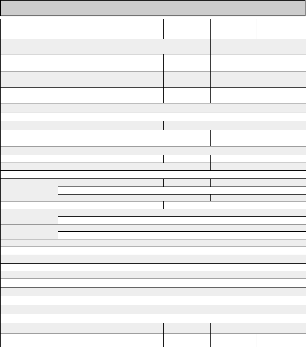
Specifications
Rinnai is continually updating and improving products. Therefore, specifications are subject to change without
prior notice.
The maximum inlet gas pressure must not exceed the value specified by the manufacturer. The minimum value
listed is for the purpose of input adjustment.
Model RL75i RL94i R98LSi R98LSi-ASME
Minimum Gas Consumption Btu/h 9,900 (NG)
10,300 (LPG) 19,000
Maximum Gas Consumption Btu/h 180,000 199,000 (NG)
190,000 (LP) 237,000
Hot water capacity (Min - Max) * 0.4 - 7.5 GPM
(1.5 - 28.5 L/min)
0.4 - 9.4 GPM
(1.5 - 35.5 L/min)
0.6 - 9.8 GPM
(2.4 - 37 L/min)
Hot water capacity (45°F rise) 6.6 GPM
(25.0 L/min)
7.1 GPM
(27.0 L/min)
8.5 GPM
(32.2 L/min)
Default Temperature Setting (no controller) 120º F (49º C)
Temperature Controller Default Setting 104º F (40º C)
Maximum Temp Setting (commercial **) 160º F (71º C) 185º F (85º C)
Maximum Temp Setting (residential)
see Temperature Ranges for more information
Selectable at 120º F (49º C) or at 140º F
(60º C) 140º F (60º C)
Minimum Temperature Setting 98º F (37º C)
Weight 51 lb (23 kg) 53 lb (24 kg) 55 lb (25 kg)
Efficiency Thermal Efficiency: 84.0%
Noise level 49 dB
Electrical Consumption
Normal 76 W 83 W 99 W
Standby 2 W
Anti-frost Protection 184 W 116 W
By-Pass Control Fixed Electronic
Minimum Gas Supply
Pressure
Natural Gas 5.0 inch W.C.
Propane 8.0 inch W.C.
Maximum Gas Supply
Pressure
Natural Gas 10.5 inch W.C.
Propane 13.5 inch W.C.
Type of Appliance Direct Vent, Temperature controlled continuous flow gas hot water system.
Operation With or without remote controls, mounted in kitchen, bathroom, etc.
Approved Gas Type Natural Gas or Propane - Ensure unit matches gas type supplied at the installation
Connections Gas Supply: 3/4" MNPT, Cold Water Inlet: 3/4" MNPT, Hot Water Outlet: 3/4" MNPT
Ignition System Direct Electronic Ignition
Electric Connections Appliance: AC 120 Volts, 60Hz. Remote Control: DC 12 Volts (Digital)
Water Temperature Control Simulation Feedforward and Feedback.
Water Supply Pressure Minimum Water Pressure: 20 PSI (Recommended 30-80 PSI for maximum
Maximum Water Supply Pressure 150 PSI
Remote Control Cable Non-Polarized Two Core Cable (Minimum 22 AWG)
Energy Star Qualified Yes Yes No (not applicable)
Certified for installation in manufactured (mobile)
homes Yes Yes No No
Energy Factor: 0.82
* Minimum flow may vary slightly depending on the temperature setting and the inlet water temperature.
** for commercial and hydronic applications requiring higher temperatures
4 VB Series Indoor LS Manual
WARNING
Safety Behaviors and Practices
• Keep the area around the appliance clear and free
from combustible materials, gasoline, and other
flammable vapors and liquids.
• Any alteration to the appliance or its controls can be
dangerous and will void the warranty.
• Always check the water temperature before entering
a shower or bath.
• Do not use this appliance if any part has been under
water. Immediately call a qualified service
technician to inspect the appliance and to replace
any part of the control system and any gas control
which has been under water.
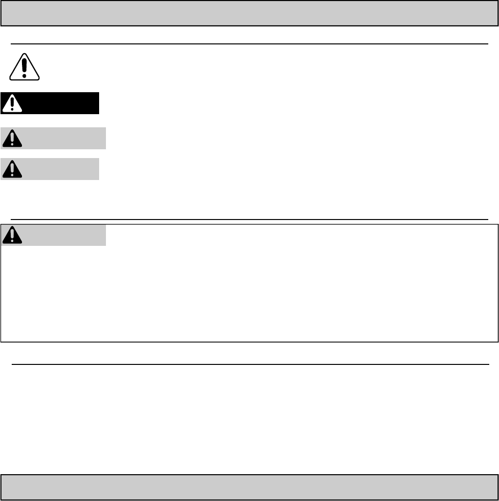
Safety Definitions
This is the safety alert symbol. This symbol alerts you to potential hazards that can kill or hurt you and
others.
Indicates an imminently hazardous situation which, if not avoided, will result in death or
serious injury.
Indicates a potentially hazardous situation which, if not avoided, could result in death or
serious injury.
Indicates a potentially hazardous situation which, if not avoided, could result in minor or
moderate injury. It may also be used to alert against unsafe practices.
DANGER
CAUTION
WARNING
Consumer Safety Information
Safety Features
• Overheat: The appliance will automatically shut
down when the appliance exceeds a predetermined
temperature.
• Flame Failure: The appliance will automatically
shut down if the burner flame is not adequate.
• Power Failure: The appliance will cut off the gas if
it loses electrical power.
• Power Surge Fuse: A glass fuse protects against
overcurrent. If the fuse blows then all indicator
lamps will be off.
• Fusible Link: In case the overheat feature does
not prevent the temperature from rising then the
fusible link will break shutting off the appliance.
The Rinnai water heater is one of the most advanced
water heaters available. It provides a continuous
supply of hot water at a preset temperature. This
appliance is direct vent where air is brought in from the
outside and combustion gases are exhausted to the
outside.
While electricity, water, and gas supplies are
connected, the Rinnai water heater produces hot water
whenever a hot water tap is open.
Ignition is electronic. There is no pilot light consuming
gas while the water heater is not being used. The gas
burner lights automatically when the hot water tap is
opened and goes out when the tap is closed.
Installation of the temperature controller is highly
recommended. The temperature controller can set the
temperature within a specific range and can provide
error codes to diagnose any problems.
The temperature of the outgoing hot water is constantly
monitored. The Rinnai water heater may adjust the
water flow in order to maintain the temperature setting.
The water flow may vary from summer to winter due to
the difference in ground water temperature.
Description of Operation
VB Series Indoor LS Manual 5
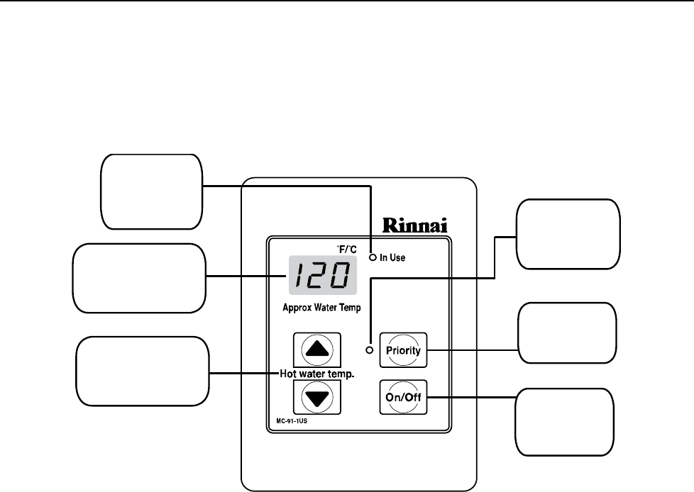
Temperature Controller
MC-91-1US & MCC-91-1US
The MC-91 controller is the standard temperature controller that is supplied with the water heater. On indoor
models it is integrated into the front panel. The MCC-91 controller is for commercial and hydronic applications
requiring higher temperatures. When the MCC-91 controller is connected, these higher temperatures are
available on all controller models in the system. Refer to the section on temperature ranges.
Dimensions (inches): 3.5 W x 4.75 H x 0.75 D
Temperature
Display
Priority
Indicator
Priority
Button
ON/OFF
Button
In Use
Indicator
Temperature
Selection
6 VB Series Indoor LS Manual
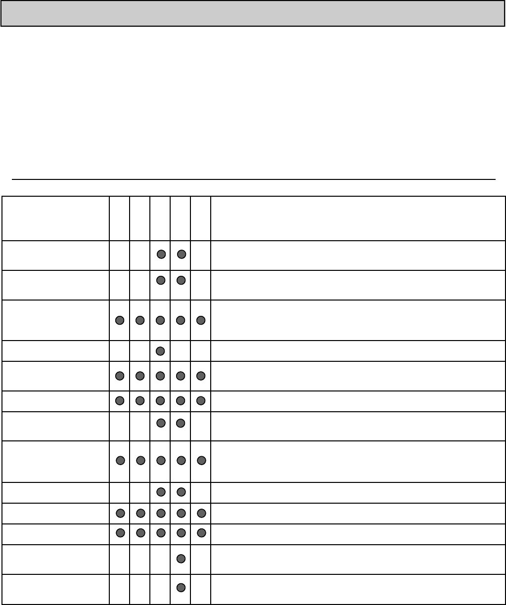
Features Available on Temperature Controllers
Operating Instructions
Features
MC-91
MC-100
BC-100
MC-502
Description
Call
Sends a short series of beeps to all controllers in the system. It is
not an intercom.
Clock 12 hour AM/PM clock. (The MC-100 must be installed for clock
to work on the BC-100.)
Function
Used on this model to set the clock or sound volume.
In Use Indicator Indicates that hot water is being supplied (i.e. a hot water tap is
open).
ON/OFF Button Used to turn the water heater ON or OFF.
Power Save Allows the temperature controller to be in an energy saving
mode.
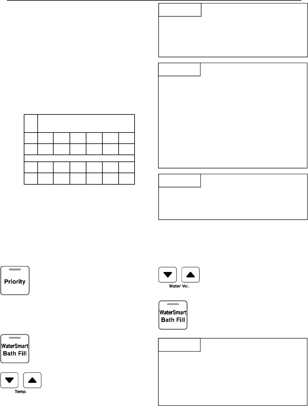
Priority Button /
Indicator
Indicates that this controller is setting the temperature . Priority
can be switched to another controller by pressing its Priority
Button when no hot water is running.
Sound Volume Used to adjust the voice prompt volume.
Temperature Display Shows the temperature setting.
Thermostat Increases or decreases the temperature setting.
Water Smart / Bath Fill
Button / Indicator
Used to select the Water Smart / Bath Fill Function to fill a bath
with a predetermined volume of water.
Water Volume Used to select the water volume for the Water Smart / Bath Fill
Function.
MCC-91
Error Codes When a fault is detected an error code flashes at the temperature
display on models MC-91, MCC-91, and MC-502; and flashes at
the clock display on models MC-100 and BC-100.
The MC-91 temperature controller is supplied with the RL75, RL94, and R98LS models. Additional functions are
available through the use of optional controllers.
There are several models of temperature controllers that can be purchased separately. Their description,
operation, and installation is provided in this manual in case additional temperature controllers are purchased and
installed.
VB Series Indoor LS Manual 7
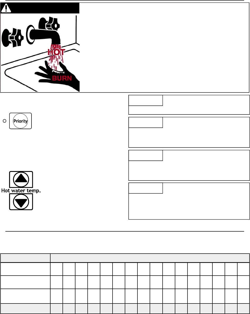
How to Set the Temperature
While any hot water is being provided,
the temperature setting can only be
adjusted between 98º F and 110º F.
NOTICE
DANGER Hot water can be dangerous, especially for infants or children, the elderly,
or infirm. There is hot water scald potential if the thermostat is set too high.
Water temperatures over 125º F (52º C) can cause severe burns or
scalding resulting in death.
Hot water can cause first degree burns with exposure for as little as:
3 seconds at 140º F (60º C)
20 seconds at 130º F (54º C)
8 minutes at 120º F (49º C)
Test the temperature of the water before placing a child in the bath or
shower.
Do not leave a child or an infirm person in the bath unsupervised.
Temperature Controller Settings
This water heater will attempt to provide hot water at the temperature setting even when the water flow is varied
or when more than 1 tap is in use. The water heater can deliver water at only one temperature setting at a time.
The available temperatures for a given model are provided below.
Model
RL75i 98 100 102 104 106 108 110 115 120 125
*
130
*
135
*
140
*
150
**
160
**
R98LSi
R98LSi-ASME 98 100 102 104 106 108 110 115 120 125 130 135 140 150
**
160
**
185
**
Temp in Celsius ºC 37 38 39 40 41 42 43 46 49 52 54 57 60 66 71 85
Temperature Settings Available (ºF)
RL94i 98 100 102 104 106 108 110 115 120 125
*
130
*
135
*
140
*
150
**
160
**
185
**
Check local codes for the maximum
water temperature setting allowed
when used in nursing homes, schools,
day care centers, and all other public
applications.
NOTICE
If a newly installed unit with a
controller has not been powered for at
least 6 hours then the temperature will
return to the default setting of 104º F
(40º C) if power is interrupted.
NOTICE
There may be a variation between the
temperature displayed on the
temperature controller and the
temperature at the tap due to weather
conditions or the length of pipe to the
water heater.
NOTICE
1. If the water heater is off, press
the ON/OFF button to turn on.
The priority can only be changed
while no hot water is running.
2. Press the “Priority button” on the
temperature controller. The
green Priority light will glow
indicating that this controller is
controlling the temperature and
that the Rinnai water heater is
ready to supply hot water.
3. Press the ▲ or ▼ buttons to
obtain the desired temperature
setting.
All hot water sources are able to
provide water at this temperature
setting until it is changed again at
this or another temperature
controller.
An older controller, MC-45, can be installed with the RL75i and RL94i by moving switch No. 6 in the bank of 6
switches to ON. Some of the temperature settings will be slightly different from the above table.
8 VB Series Indoor LS Manual
Suggested temperatures are
• Kitchen 120 ºF (49º C)
• Shower 98 - 110 ºF (37 - 43 ºC)
• Bath Fill 102 - 110 ºF (39 - 43 ºC)
These temperatures are suggestions only.
A temperature lower than 98º F (37º C) can be
obtained at the tap by mixing with cold water.
To change the temperature scale from Celsius to
Fahrenheit or vice versa, press and hold the “On/Off”
button for 5 seconds while the water heater is OFF.
Temperature Options Without a Temperature Controller
The default temperature setting for this appliance installed without a temperature controller is 120º F (49º C). If
desired, the temperature setting can be changed to 140º F (60º C) by adjustment of a switch.
In the SW1 bank of 8 switches, set switch 5 to ON to obtain 140º F water temperature setting. Set switch 5 to
OFF (default) to obtain 120º F water temperature setting.
If a temperature controller is installed, then switch 5 has no effect on temperature settings.
WARNING
DO NOT adjust the other switches
unless specifically instructed to do
so.
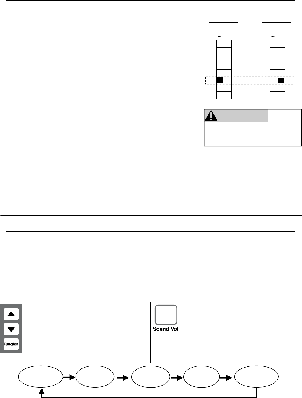
Setting the Sound Volume (Voice Prompt)
BC-100V Press the “Sound Vol.” button to
adjust the voice prompt volume.
The default sound volume is set
to Medium. Each subsequent
press of the button cycles
through the volume levels in the
order below.
MC-100V Press the “Function” button to
adjust the voice prompt
volume. The default sound
volume is set to Medium.
Each subsequent press of the
▲ or ▼ button cycles through
the volume levels in the order
below.
Medium Volume
(default) High Volume Off Volume
(beep) Off Sound
(no beep) Low Volume
The MCC-91 controller is intended for commercial and hydronic
applications only. If an MCC-91 controller is used in a residential
dwelling for a hydronics application, a mixing valve must also be
installed to limit the potable hot water temperature to a safe
temperature. Water temperatures over 125º F (52º C) can cause severe
burns or scalding. Refer to the Danger Alert on water temperatures.
Rinnai shall not, in any event, be liable for damages resulting from such
misuse or misapplication.
** MCC-91 Temperature Controller
These settings require the MCC-91 controller. When the MCC-91
controller is connected, these higher temperatures are available on all
controller models in the system. Use of an MCC-91 controller in a
residential dwelling will reduce the warranty coverage to that of a
commercial warranty application.
* Re-setting the Maximum Temperature (RL75 and RL94 only)
Models RL75 and RL94 have a default maximum temperature of 120º F
(49º C) and an option to increase the maximum temperature to 140 ºF
(60 ºC). Temperature settings from 125-140 ºF (52-60 ºC) are available
by setting switch 6 to ON in the SW1 bank of 8 switches.
Temperature Controller Settings
Switch No.
F
O
F
8
5
7
6
4
3
ON
1
2
Switch No.
F
O
F
8
5
7
6
4
3
ON
1
2
Maximum Temperature
120º F (49º C) 140 ºF (60 ºC)
VB Series Indoor LS Manual 9
Setting the Water Volume
Using the Water Smart / Bath Fill Function
Overview
This function is exclusive to the BC-100V temperature
controller. The bath fill function allows the consumer
to fill a tub with a preset volume of water at a preset
temperature. This is done by pressing the bath fill
button on the BC-100V controller while no hot water is
flowing and then opening only the hot water tap. The
water heater will stop the hot water flow when the
preset volume has been reached. The hot water tap
should then be closed and the bath fill button pressed.
The temperature settings for the bath fill function are
limited to those in the table below.
Power
Loss
If power is lost during the bath fill
function, the water heater will shut
down but the water will continue to
flow. When power returns, the water
shuts off and Error Code 03 appears
on the controller.
If power is lost after the bath has filled
but before the bath fill function button
is de-selected, then the water will not
flow during the power loss or after the
power is returned. Once power
returns, close the hot water tap and
de-select the bath fill function. No
error code appears.
NOTICE
Multiple
Water
Heaters
The bath fill function will not work
properly if it is connected to multiple
water heaters. The tub will overfill
because the bath fill function is not
able to measure the water volume
when connected to multiple water
heaters.
NOTICE
Anti-scald
Fixtures
Do not use with single handle fixtures
that have anti-scald features built into
them. These fixtures allow a
predetermined amount of cold water
which is not taken into account by the
bath fill function.
NOTICE
1. Press the “Priority” button on the
temperature controller. The green
Priority light will glow indicating
that this controller is controlling
the temperature and that the
Rinnai water heater is ready to
supply hot water.
2. Press the “Water Smart Bath Fill”
button to set the water volume
and temperature.
3. Press the “Temp” ▲ or ▼ buttons
to obtain the desired temperature
setting.
To Prevent
Over Filling
Be careful not to overfill the bath. An
average bath volume is 60 gallons.
When filling the bath using this
function for the first time:
•Monitor and remain by the bath while
the water is running.
•Use a low bath fill volume less than
25 gallons
NOTICE
The default volume is set to 25 gallons. The volume
can be set between 10 and 120 gallons.
4. Press the “Water Vol.”▲ or ▼
buttons to obtain the desired
water volume in gallons.
5. Press the “Water Smart Bath Fill”
button.
Bath Fill Temperature Settings
Available
ºF 98 100 102 104 106 108
ºC 37 38 39 40 41 42
ºF 110 112 114 116 118 120
ºC 43 44 46 47 48 49
10 VB Series Indoor LS Manual
Setting Controller to Mute
To eliminate the beeps when keys are pressed or to turn the beeps back on, press and hold both the ▲and ▼
buttons until a beep is heard (approximately 5 seconds).
Models MC-91 and MCC-91
Using the Water Smart / Bath Fill Function
Setting the Clock
MC-100V Press the “Function” button twice within 10 seconds to set the clock. Press the ▲ or
▼ button to reach the desired time. The clock on the BC-100V automatically shows
the time which has been set on the MC-100V.
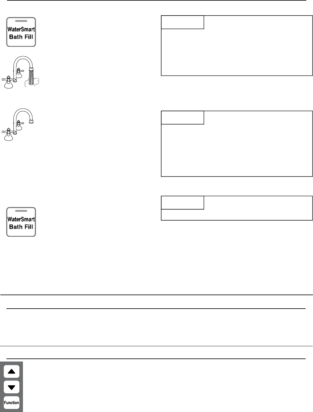
Filling the Tub
1. Press the “Water Smart / Bath Fill”
button once. The button will
illuminate, and a tone will sound.
2. The voice prompt will announce
“The hot water system is ready.
Open the hot water tap.”
Make sure the water volume is set.
Refer to “Setting the Water
Volume” on the previous page.
Open the hot water tap. The “In
Use” indicator will illuminate on
MC-100V and BC-100V controllers.
The hot water will begin to flow.
3. When the preset volume of water
has been produced then
4. Turn off the bath hot water tap and
push the Bath Fill button. The
water heater will not allow hot
water to flow from any source until
the “Water Smart / Bath Fill” button
is pushed.
The button light will go out.
HOT
COLD
ON!
To Stop the
Bath Fill
Before it
Finishes
To stop the water flow during the Bath
Fill function, press the “Water Smart /
Bath Fill” button. The button will flash
and the voice prompt will announce,
“Hot water is not available. Turn off
all hot water taps and push the Bath
Fill button.” Follow the voice prompt
instructions.
NOTICE
•the water flow will cease
•the “Water Smart / Bath Fill”
button will flash
•a tone will sound
•the voice prompt will announce,
“Bath fill is complete. Turn
off the bath hot water tap and
push the Bath Fill button.”
When
Other Taps
Are Open
During the bath fill function, any hot
water flowing at other locations,
subtracts from the total amount of
water for the bath. For example if the
bath fill function is set for 50 gallons
and 5 gallons of hot water are used at
other locations during the fill period
then the bath will only fill with 45
gallons.
NOTICE
HOT
COLD
ON!
During the operation of the bath fill
function, the MC-91 “In Use” indicator
does not light up.
NOTICE
VB Series Indoor LS Manual 11
WARNING
Turn off the electrical power supply, the manual gas
valve and the manual water control valve whenever
servicing the unit.
Repairs and maintenance should be performed by a
qualified service technician. The appliance should be
inspected annually by a qualified service technician.
Verify proper operation after servicing.
Cleaning
It is imperative that control compartments, burners,
and circulating air passageways of the appliance be
kept clean.
Clean as follows:
1. Turn off and disconnect electrical power. Allow to
cool.
2. Close the water shut off valves. Remove and clean
the water inlet filter.
3. Remove the front panel by removing 4 screws.
4. Use pressurized air to remove dust from the main
burner, heat exchanger, and fan blades. Do not
use a wet cloth or spray cleaners on the burner.
Do not use volatile substances such as benzene
and thinners. They may ignite or fade the paint.
5. Use soft dry cloth to wipe cabinet.
Vent System
The vent system should be inspected at least annually
for blockages or damage.
Motors
Motors are permanently lubricated and do not need
periodic lubrication. Keep fan and motor free of dust
and dirt by cleaning annually.
Temperature Controller
Use a soft damp cloth to clean the temperature
controller. Do not use solvents.
Lime / Scale Build-up
If you receive Error Code “LC”, refer to the procedure,
Flushing the Heat Exchanger. Refer to the section on
Water Quality to see if your water needs to be treated
or conditioned. (When checking maintenance code
history, “00” is substituted for “LC”.)
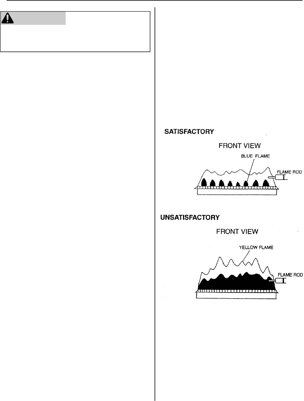
Visual Inspection of Flame
The burner must flame evenly over the entire surface
when operating correctly. The flame must burn with a
clear, blue, stable flame. See the parts breakdown of
the burner for the location of the view ports.
The flame pattern should be as shown in the figures
below.
Snow Accumulation
Keep the area around flue terminal free of snow and
ice. The appliance will not function properly if the
intake air or exhaust is impeded (blocked or partially
blocked) by obstructions.
Maintenance
12 VB Series Indoor LS Manual
Error Codes
The Rinnai water heater has the ability to check its own operation continuously. If a fault occurs, an error code
will flash on the display of the temperature controller. This assists with diagnosing the fault and may enable you
to overcome a problem without a service call. Please identify the code displayed when inquiring about service.
Code Fault Remedy
02 No burner operation during
freeze protection mode
Service Call
03 Power interruption during
Bath Fill (Water will not flow
when power returns).
Turn off all hot water taps. Press ON/OFF twice.
10 Air Supply or Exhaust
Blockage
Ensure Rinnai approved venting materials are being used.
Check that nothing is blocking the flue inlet or exhaust.
Check all vent components for proper connections.
Ensure vent length is within limits.
Ensure condensation collar was installed correctly.
Verify dip switches are set properly.
Check fan for blockage.
11 No Ignition Check that the gas is turned on at the water heater, gas meter, or cylinder.
Ensure gas type and pressure is correct.
Ensure gas line, meter, and/or regulator is sized properly.
Bleed all air from gas lines.
Verify dip switches are set properly.
Ensure appliance is properly grounded.
Disconnect EZConnect™ or MSA controls to isolate the problem.
Ensure igniter is operational.
Check igniter wiring harness for damage.
Check gas solenoid valves for open or short circuits.
Remove burner cover and ensure all burners are properly seated.
Remove burner plate and inspect burner surface for condensation or debris.
12 Flame Failure Check that the gas is turned on at the water heater and gas meter. Check for
obstructions in the flue outlet.
Ensure gas line, meter, and/or regulator is sized properly.
Ensure gas type and pressure is correct.
Bleed all air from gas lines.
Ensure proper Rinnai venting material was installed.
Ensure condensation collar was installed properly.
Ensure vent length is within limits.
Verify dip switches are set properly.
Ensure appliance is properly grounded.
Disconnect keypad.
Disconnect EZConnect™ or MSA controls to isolate the problem.
Check power supply for loose connections.
Check power supply for proper voltage and voltage drops.
Ensure flame rod wire is connected.
Check flame rod for carbon build-up.
Disconnect and reconnect all wiring harnesses on unit and PC board.
Check for DC shorts at components.
Check gas solenoid valves for open or short circuits.
Remove burner plate and inspect burner surface for condensation or debris.
Check the ground wire for the PC board.
Some of the checks below may need to be done by a qualified service technician. Call a
service technician for any remedy that involves gas or electricity. Call a service
technician if you have any doubt or reservation about performing the remedy yourself.
WARNING
VB Series Indoor LS Manual 13
Code Fault Remedy
16 Over Temperature
Warning
Check for restrictions in air flow around unit and vent terminal.
Check for low water flow in a circulating system causing short-cycling.
Check for foreign materials in combustion chamber and/or exhaust piping.
Check for clogged heat exchanger.
32 Outgoing Water
Temperature Sensor
Fault
Check sensor wiring for damage.
Measure resistance of sensor.
Clean sensor of scale build-up.
Replace sensor.
33 Heat Exchanger
Outgoing Temperature
Sensor Fault
Check sensor wiring for damage.
Measure resistance of sensor.
Clean sensor of scale build-up.
Replace sensor.
34 Combustion Air
Temperature Sensor
Fault
Check for restrictions in air flow around unit and vent terminal.
Check sensor wiring for damage.
Measure resistance of sensor.
Clean sensor of scale build-up.
Ensure fan blade is tight on motor shaft and is in good condition.
Replace sensor.
52 Modulating Solenoid
Valve Signal Abnormal
Check modulating gas solenoid valve wiring harness for loose or damaged terminals.
Measure resistance of valve coil.
61 Combustion Fan Failure Ensure fan will turn freely.
Check wiring harness to motor for damaged and/or loose connections.
Measure resistance of motor winding.
65 Water Flow Control Fault The water flow control valve has failed to close during the bath fill function. Immediately turn
off the water and discontinue the bath fill function. Contact a state qualified or licensed
contractor to service the appliance.
71 Solenoid Valve Circuit
Fault
Replace the PC Board.
72 Flame Sensing Device
Fault
Ensure flame rod is touching flame when unit fires.
Check all wiring to flame rod for damage.
Remove flame rod and check for carbon build-up; clean with sand paper.
Check inside burner chamber for any foreign material blocking flame at flame rod.
Measure micro amp output of sensor circuit with flame present.
Replace flame rod.
LC Scale Build-up in Heat
Exchanger (when
checking maintenance
code history, “00” is
substituted for “LC”)
Flush heat exchanger. Refer to instructions in manual.
Replace heat exchanger.
NOTE: The LC code is the only error code that will allow the unit to keep running. The
display will alternate between the LC code and the temperature setting. The controller will
continue to beep. The LC code will reset if power is turned off and then on.
No
code
Nothing happens when
water flow is activated.
Clean inlet water supply filter.
On new installations ensure hot and cold water lines are not reversed.
Check for bleed over. Isolate unit from building by turning off cold water line to building.
Isolate the circulating system if present. Open your pressure relief valve; if water is
flowing, there is bleed over in your plumbing.
Ensure you have at least the minimum flow rate required to fire unit.
Ensure turbine spins freely.
Measure the resistance of the water flow control sensor.
Check for DC shorts at components.
31 Burner Sensor Error Measure resistance of sensor.
Replace sensor.
73 Burner Sensor Circuit
Error
Check sensor wiring and PC board for damage.
Replace sensor.
14 Thermal Fuse Check gas type of unit and ensure it matches gas type being used.
Check for restrictions in air flow around unit and vent terminal.
Check for low water flow in a circulating system causing short-cycling.
Ensure dip switches are set to the proper position.
Check for foreign materials in combustion chamber and/or exhaust piping.
Check heat exchanger for cracks and/or separations.
Check heat exchanger surface for hot spots which indicate blockage due to scale build-up.
Refer to instructions in manual for flushing heat exchanger.
Measure resistance of safety circuit.
Ensure high fire and low fire manifold pressure is correct.
Check for improper conversion of product.
Error Codes

14 VB Series Indoor LS Manual
Trouble Shooting for Common Issues
I don’t have any hot water when I open the tap.
Make sure there is gas, water, and electricity to the
Rinnai water heater (power is turned on and the gas is
turned on).
When I was using the hot water, the water got cold.
If you adjusted the flow from the tap to lessen it, you
may have gone below the minimum flow required. The
Rinnai water heater requires a minimum flow rate to
operate. (See the specification page for the flow rate
of your model.)
If you are experiencing issues with higher temperature
settings, then Rinnai recommends reducing the
temperature setting. Selecting a temperature closer to
that which is actually used at the faucet will increase
the amount of hot water being delivered to the faucet,
due to less cold water mixing at the fixture.
White smoke comes out of the exhaust.
During colder weather when the exhaust temperature
is much hotter than the outside air, the exhaust fumes
condense producing water vapor.
When I open a hot tap, I do not immediately get hot
water.
Hot water must travel through your plumbing from the
Rinnai water heater to the faucet. The time period for
hot water to reach your fixture is determined by the
amount of water in the plumbing system between the
water heater and the fixture, water pressure, and the
flow rate of the fixture.
After I turn off the hot water tap, the fan on the
Rinnai water heater continues to run.
The fan is designed to continue running for a short time
after the flow of water stops. This is to ensure constant
water temperatures during rapid starting and stopping,
as well as exhausting any residual gas flue products
from the unit.
Consideration of care for your water heater should
include evaluation of water quality. If the water quality
exceeds the target levels provided in the table, you
may want to treat or condition the water.
* Source: Part 143 National Secondary Drinking Water
Regulations
Maximum Level
Total Hardness Up to 200 mg / L
Aluminum * Up to 0.2 mg / L
Chlorides * Up to 250 mg / L
Copper * Up to 1.0 mg / L
Iron * Up to 0.3 mg / L
Manganese * Up to 0.05 mg / L
pH * 6.5 to 8.5
TDS (Total Dissolved
Solids) *
Up to 500 mg / L
Zinc * Up to 5 mg / L
Water Quality
Accessing Operating Information
To display the most recent error codes press and hold the “On/Off” button for 2 seconds. While holding the “On/
Off” button press the ▲ button. The last 9 error codes will flash one after the other. To exit this mode press the
“On/Off” and ▲ button as before.
To display the water flow through the water heater press and hold the ▲ button for 2 seconds and without
releasing the ▲ button press the “On/Off” button.
To display the outlet water temperature press and hold the ▼ button for 2 seconds and without releasing the ▼
button press the “On/Off” button.
Models MC-91 and MCC-91
VB Series Indoor LS Manual 15
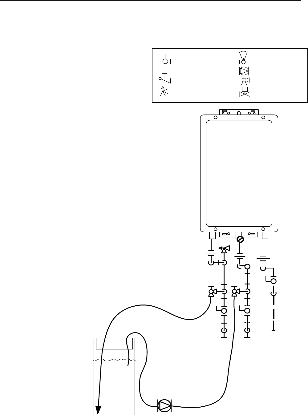
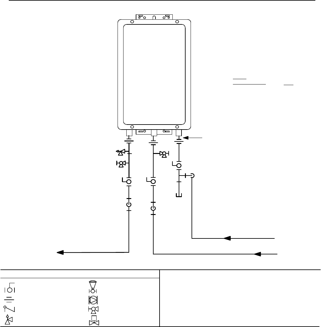
Water Heater
Pressure Relief Valve
3/4" Ball Valve
3/4" Union
Check Valve
S
Pressure Regulator
Circulating Pump
Solenoid Valve
Boiler Drain Valve
KEY
Gas
Supply
V1
V3
V2
V4
H1
H2
H3
Circulating Pump
Cold
Water
Line
Hot
Water
Line
n-line
Filter
I
Rinnai
Flushing the Heat Exchanger (Error Code: LC or 00)
An “LC” or “00” error code indicates the unit is beginning to lime up and must be flushed. Failure to flush the
appliance will cause damage to the heat exchanger. Damage caused by lime build-up is not covered by the unit’s
warranty. After flushing, reset the LC fault code by turning off the power to the unit and turning the power back
on.
1. Disconnect electrical power to the water heater.
2. Close the shutoff valves on both the hot water and
cold water lines (V3 and V4).
3. Connect pump outlet hose (H1) to the cold water
line at service valve (V2).
4. Connect drain hose (H3) to service valve (V1).
5. Pour 4 gallons of undiluted virgin, food grade,
white vinegar into pail.
6. Place the drain hose (H3) and the hose (H2) to
the pump inlet into the cleaning solution.
7. Open both service valves (V1 and V2) on the hot
water and cold water lines.
8. Operate the pump and allow the cleaning solution
to circulate through the water heater for 1 hour at
a rate of 4 gallons per minute (15.1 liters per
minute).
9. Turn off the pump.
10. Rinse the cleaning solution from the water heater
as follows:
a. Remove the free end of the drain hose (H3)
from the pail.
b. Close service valve, (V2), and open shutoff
valve, (V4). Do not open shutoff valve, (V3).
c. Allow water to flow through the water heater for
5 minutes
d. Close service valve, (V1), and open shutoff
valve, (V3).
11. Disconnect all hoses.
12. With (V4) closed, remove the in-line filter at the
cold water inlet and clean out any residue. Place
filter back into unit and open (V4).
13. Restore electrical power to the water heater.
Cleaning solution is 4 gallons of
undiluted virgin, food grade,
white vinegar.
CLEAN THERMISTORS
Remove and clean thermistors
with a soft cloth or sponge after
removing O-rings.
16 VB Series Indoor LS Manual
Only properly trained and qualified installers
should install this appliance. The warranty may
be voided due to improper installation or
installation by a non-qualified installer.
Rinnai highly recommends all installers attend a
product knowledge class.
For information on a Rinnai Training Course or
for questions on installation call 1-800-621-
9419.
General Instructions
• This appliance must be installed by a state qualified
or licensed contractor. It is the responsibility of the
person having the water heater installed to ensure
the installing contractor has proper licenses and
permits for installing water heaters in your location.
Rinnai highly recommends that installers attend a
product knowledge class to ensure customer
satisfaction and warranty coverage. Failure to
comply with state and local codes pertaining to
water heater installations may void the warranty.
• This appliance is not to be installed outdoors.
• A qualified installer or service technician should
install the appliance, inspect it, and leak test it
before use.
• The installation must conform with local codes or, in
the absence of local codes, with the National Fuel
Gas Code, ANSI Z223.1/NFPA 54, or the Natural
Gas and Propane Installation Code, CSA B149.1. If
installed in a manufactured home, the installation
must conform with the Manufactured Home
Construction and Safety Standard, Title 24 CFR,
Part 3280 and/or CAN/SCA Z240 MH Series, Mobile
Homes.
• The appliance, when installed, must be electrically
grounded in accordance with local codes or, in the
absence of local codes, with the National Electrical
Code, ANSI/NFPA 70, or the Canadian Electrical
Code, CSA C22.1.
• The appliance and its appliance main gas valve
must be disconnected from the gas supply piping
system during any pressure testing of that system at
test pressures in excess of 1/2 psi (3.5 kPa) (13.84
in W.C.).
• The appliance must be isolated from the gas supply
piping system by closing its individual manual
shutoff valve during any pressure testing of the gas
supply piping system at test pressures equal to or
less than 1/2 psi (3.5 kPa) (13.84 in W.C.).
• Follow the installation instructions and those in Care
and Maintenance for adequate combustion and
ventilation air.
• The appliance should be located in an area where
water leakage of the unit or connections will not
result in damage to the area adjacent to the
appliance or to lower floors of the structure. When
such locations cannot be avoided, it is
recommended that a suitable drain pan, adequately
drained, be installed under the appliance. The pan
must not restrict combustion air flow.
• The flow of combustion and ventilation air shall not
be obstructed. Combustion air shall not be supplied
from occupied spaces.
• This appliance is not suitable for use in an
application such as a pool or spa heater that uses
chemically treated water . (This appliance is
suitable for filling large or whirlpool bath tubs with
potable water.)
• If a water heater is installed in a closed water supply
system, such as one having a backflow preventer in
the cold water supply line, means shall be provided
to control thermal expansion. Contact the water
supplier or local plumbing inspector on how to
control thermal expansion.
• Should overheating occur or the gas supply fail to
shut off, turn off the manual gas control valve to the
appliance.
• Keep the air intake location free of chemicals such
as chlorine or bleach that produce fumes. These
fumes can damage components and reduce the life
of your appliance.
• For gas type conversion, contact Rinnai.
WARNING
Do not use substitute materials.
Use only parts certified with the appliance.
Installation Instructions
RL75i .................. REU-VB2528FFUD-US
RL94i .................. REU-VB2735FFUD-US
R98LSi ................ REU-VA3237FFU-US
R98LSi-ASME .... REU-VA3237FFU-ASME
The VB series (RL75i, and RL94i) are certified for installation in
manufactured (mobile) homes.
VB Series Indoor LS Manual 17
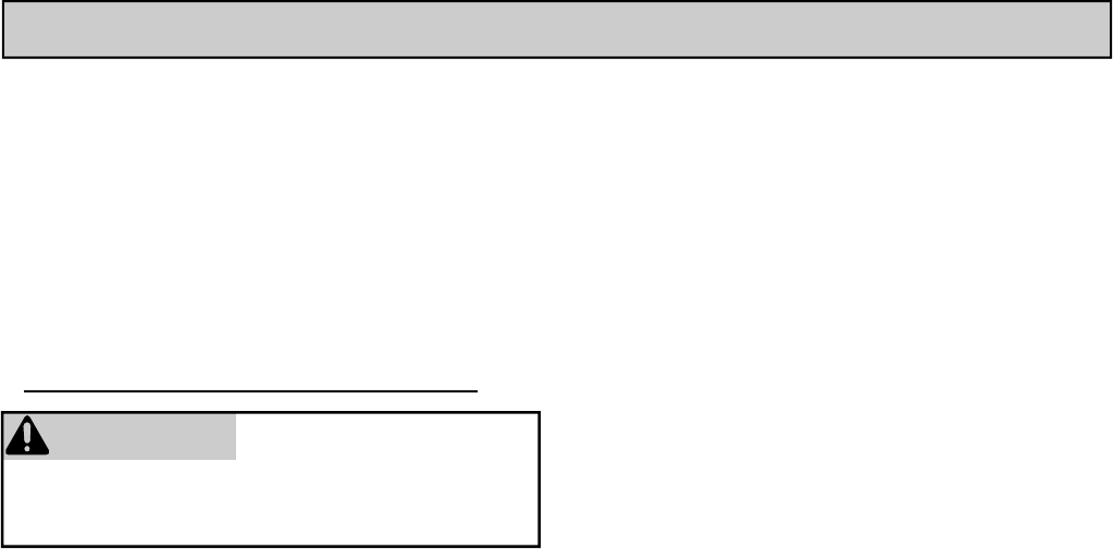
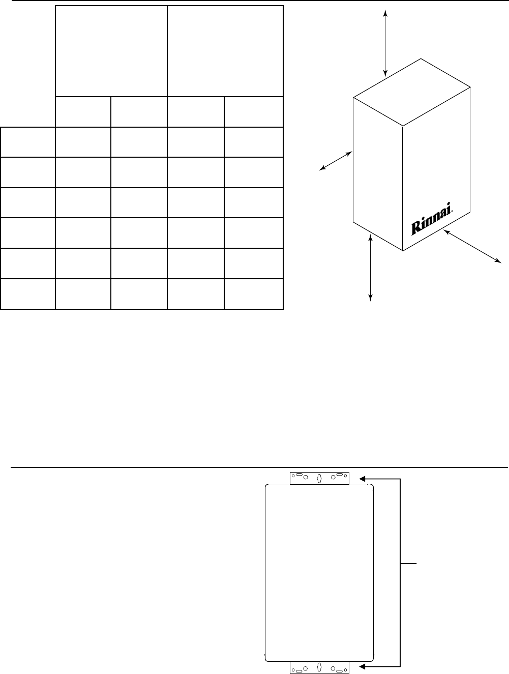
Clearances from Appliance
1. Identify the installation location and confirm that
the installation will meet all required clearances.
2. Securely attach the water heater to the wall using
any of the holes in the wall installation brackets
which are at the top and bottom of the water
heater. Ensure that the attachment strength is
sufficient to support the weight. Refer to the
weight of the water heater in the Specifications
section.
NOTE: Rinnai water heaters should be installed in an
upright position. Do not install upside down or on its
side.
Attachment of the Water Heater
wall installation
brackets
to Combustibles to Non-
Combustibles
RL75i
RL94i R98LSi RL75i
RL94i R98LSi
Top of
Heater
6 inches **
(152 mm)
12 inches
(305 mm)
2 inches **
(51 mm)
2 inches
(51 mm)
Back of
Heater
0 (zero) 0 (zero) 0 (zero) 0 (zero)
Front of
Heater
6 inches
(152 mm)
6 inches
(152 mm)
6 inches
(152 mm)
6 inches
(152 mm)
Sides of
Heater
2 inches
(51 mm)
2 inches
(51 mm)
1/2 inch
(13 mm)
1/2 inch
(13 mm)
Ground/
Bottom
12 inches
(305 mm)
12 inches
(305 mm)
12 inches
(305 mm)
2 inches
(51 mm)
Vent 0 (zero) 4 inches * 0 (zero) 0 (zero)
* 4 inches (102 mm) for enclosed area; 1 inch (26 mm) for unenclosed area.
The clearance for servicing is 24 inches in front of the water heater.
For closet installation: clearance is 6 inches (152 mm) from the front.
** 0 inches from vent components and condensate drain line.
to side
to front
to top
to ground/bottom

18 VB Series Indoor LS Manual
Gas Piping
General Instructions
• A manual gas control valve must be placed in the
gas supply line to the Rinnai water heater. A union
can be used on the connection above the shut off
valve for the future servicing or disconnection of the
unit.
• Check the type of gas and the gas inlet pressure
before connecting the Rinnai water heater. If the
Rinnai water heater is not of the gas type that the
building is supplied with, DO NOT connect the water
heater. Contact the dealer for the proper unit to
match the gas type.
• Check the gas supply pressure immediately
upstream at a location provided by the gas
company. Supplied gas pressure must be within the
limits shown in the Specifications section.
• Before placing the appliance in operation all joints
including the heater must be checked for gas
tightness by means of leak detector solution, soap
and water, or an equivalent nonflammable solution,
as applicable. (Since some leak test solutions,
including soap and water, may cause corrosion or
stress cracking, the piping shall be rinsed with water
after testing, unless it has been determined that the
leak test solution is non-corrosive.)
• Always use approved connectors to connect the unit
to the gas line. Always purge the gas line of any
debris before connection to the water heater.
• The gas supply line shall be gas tight, sized, and so
installed as to provide a supply of gas sufficient to
meet the maximum demand of the heater and all
other gas consuming appliances at the location
without loss of pressure.
• Any compound used on the threaded joint of the gas
piping shall be a type which resists the action of
liquefied petroleum gas (propane / LPG).
• Refer to an approved pipe sizing chart if in doubt
about the size of the gas line.
Electrical Connection
The water heater requires 120 VAC, 60 Hz power from a properly grounded circuit.
If using the 6 foot long power cord, plug it into a standard 3 prong 120 VAC, 60 Hz properly grounded wall outlet.
The wiring diagram is located on the Technical Sheet attached to the inside of the front cover.
The water heater must be electrically grounded in accordance with local codes, or in the absence of local codes
with the National Electrical Code, ANSI/NFPA 70 and/or the CSA C22.1, Canadian Electrical Code.
Error Indication or Air Handler Control Switch (RL75i, and RL94i only)
When using the Rinnai water heater with an Error Indication Switch, switch No. 4 in the bank of 8 switches should
be in the off position. This is the default position.
To connect the water heater to the Rinnai Air Handler, the Control Switch is necessary to function as the electrical
connection. When the Control Switch is functioning as the electrical connection between the water heater and air
handler, switch No. 4 in the bank of 8 switches should be in the on position.
The Error Indication Switch and the Rinnai Air Handler Control Switch are optional products available from Rinnai.
Installation instructions are included with these products.
VB Series Indoor LS Manual 19
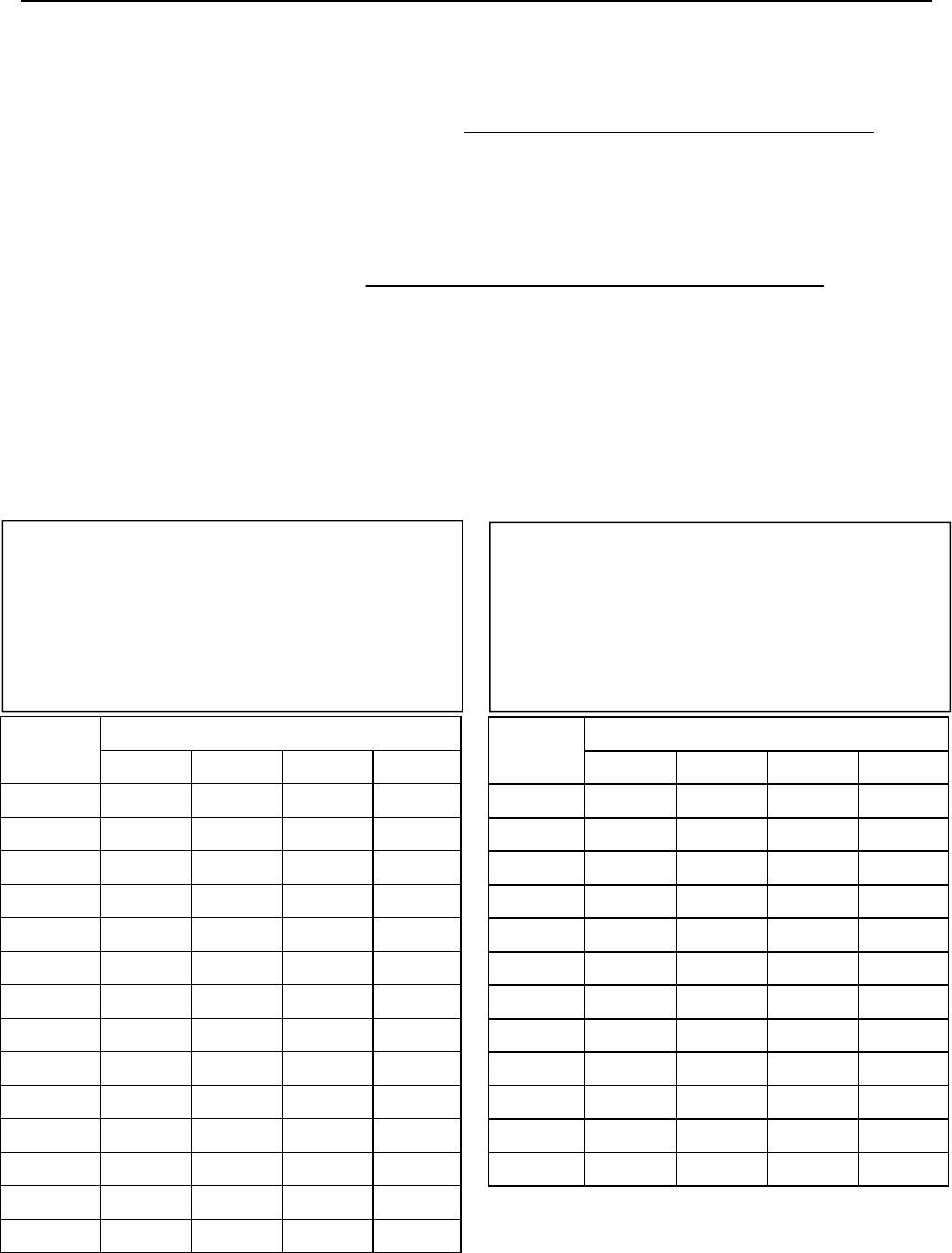
Pipe Sizing Procedure - Example
1. For some tables, you will need to determine the cubic feet per hour of gas required by dividing the gas input
by the heating value of the gas (available from the local gas company). The gas input needs to include all gas
products at the location and the maximum BTU usage at full load when all gas products are in use.
Gas Input of all gas products (BTU / HR)
Cubic Feet per Hour (CFH) =
Heating Value of Gas (BTU / FT
3 )
2. Use the table for your gas type and pipe type to find the pipe size required. The pipe size must be able to
provide the required cubic feet per hour of gas or the required BTU/hour.
Example: The heating value of natural gas for your location is 1000 BTU/FT3. The gas input of the RL94i is
199,000 BTU/HR. Additional appliances at the location require 65,000 BTU/hr. Therefore the cubic
feet per hour = (199,000 + 65,000) / 1000 = 264 FT3/HR. If the pipe length is 10 feet then the 3/4 inch
pipe size is capable of supplying 264 FT3/HR of natural gas.
Gas Piping
The gas supply must be capable of handling the entire gas load at the location. Gas line sizing is based on gas
type, the pressure drop in the system, the gas pressure supplied, and gas line type. For gas pipe sizing in the
United States, refer to the National Fuel Gas Code, NFPA 54. For Canadian gas pipe sizing, refer to the Natural
Gas and Propane Installation Code CAN/CSA B149.1. The below information is provided as an example. The
appropriate table from the applicable code must be used.
Pipe Size (inches)
3/4 1 1 1/4 1 1/2
10 273 514 1060 1580
20 188 353 726 1090
30 151 284 583 873
40 129 243 499 747
50 114 215 442 662
60 104 195 400 600
70 95 179 368 552
80 89 167 343 514
90 83 157 322 482
100 79 148 304 455
125 70 131 269 403
150 63 119 244 366
175 58 109 224 336
200 54 102 209 313
Length Length Pipe Size (inches)
1/2 3/4 1 1 1/4
10 291 608 1150 2350
20 200 418 787 1620
30 160 336 632 1300
40 137 287 541 1110
50 122 255 480 985
60 110 231 434 892
80 101 212 400 821
100 94 197 372 763
125 89 185 349 716
150 84 175 330 677
175 74 155 292 600
200 67 140 265 543
Pipe Sizing Table - Natural Gas Pipe Sizing Table - Propane Gas
Inlet Pressure: less than 2 psi (55 inches W.C.)
Pressure Drop: 0.3 inches W.C.
Specific Gravity: 0.60
Inlet Pressure: 11.0 inches W.C.
Pressure Drop: 0.5 inches W.C.
Specific Gravity: 1.50
Schedule 40 Metallic Pipe
Capacity in cubic feet per hour
Schedule 40 Metallic Pipe
Capacity in Thousands of BTU per Hour
20 VB Series Indoor LS Manual
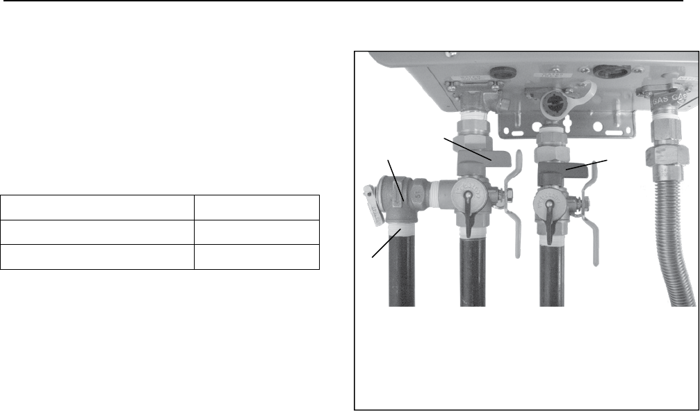
Isolation Valves and Pressure Relief Valve (RL75i and RL94i)
Water Piping
The isolation valves provide the ability to isolate the
water heater from the structure’s plumbing and allow
quick access to flush the heat exchanger. Check with
local codes to determine if a pressure and temperature
relief valve is required. The included valves meet
American National Standard (ANSI Z21.10.3) /
Canadian Standard (CSA 4.3) and are ANSI/NSF 61
approved for potable water.
Isolation Valves Installation Instructions:
1. Wrap the ends of the threaded water inlet & outlet
on the tankless water heater,as well as the
threaded end of the approved pressure relief valve
with a minimum of 5 wraps of Teflon® tape.
2. Screw the pressure relief valve into the 3/4”
threads opposite the wing handle on the HOT
water service valve. (RED drain handle) (see
Pressure Relief Valve Section for proper
installation requirements)
3. Loosen the 3/4” union nut on the HOT water valve
and connect to the HOT water outlet on the
tankless water heater. If nut is removed, ensure
that you realign the tailpiece accurately to the
valve and that the black washer is positioned such
that the raised metal edge of the valve is inside
the washer.
4. Align the direction of the HOT water drain to the
desired position.
5. Tighten the union assembly to the HOT water
valve using approximately 15 foot lbs of torque.
6. Repeat steps 3-5 for the COLD water valve.
(BLUE drain handle) for connection to the COLD
water inlet on the tankless water heater.
7. Connect the INLET on the COLD water valve to
the MAIN SOURCE of the water supply.
8. Connect the OUTLET on the HOT water valve to
the HOT WATER plumbing system.
9. Ensure that both drain valve lever handles are in
the closed position (perpendicular to the drain
portion of the body).
Isolation Valve (Cold) 107000081
Isolation Valve (Hot) 107000083
Pressure Relief Valve (PRV) 107000085
Pressure Relief Valve Installation Instructions:
The PRV must be connected by the threaded
connection opposite the wing handle on the hot water
valve (designated by the RED drain handle) or the
threaded connection on the side of the relocation
fitting above the hot water valve. Installation must
maintain a ¾” port size with no shut off valve or line
restriction in-between the appliance and the PRV. The
discharge line from the PRV should pitch downward
and terminate 6” above drains where discharge will be
clearly visible. The discharge end of the line shall be
plain (unthreaded) and a minimum of ¾” in diameter.
The discharge line material must be suitable for water
at least 180º Fahrenheit and can be no more than 30
feet in length and contain no more than 4 elbows or
bends. No valve of any type may be installed in the
discharge line of the pressure relief valve.
Pressure Relief Valve Maintenance:
For proper care of this approved pressure relief valve,
it is recommended that the valve is manually operated
once a year. In doing so, it will be necessary to
take precautions with regard to the discharge of
potentially scalding hot water under pressure. Ensure
discharge has a place to flow. Contact with your body
or other property may cause damage or harm.
Please note that only the PRV in this package is
certified by CSA International as an approved item.
A Pressure Relief Valve (PRV)
B PRV Discharge Outlet
C Hot Ball Valve Drain Handle
D Cold Ball Valve Drain Handle
A
B
C
D

VB Series Indoor LS Manual 21
• A manual water control valve must be placed in the
water inlet connection to the Rinnai water heater
before it is connected to the water line. Unions may
be used on both the hot and cold water lines for
future servicing and disconnection of the unit.
• The piping (including soldering materials) and
components connected to this appliance must be
approved for use in potable water systems.
• Purge the water line to remove all debris and air.
Debris will damage the Rinnai water heater.
• Toxic chemicals such as those used for boiler water
treatment are not to be introduced to the potable
water used for space heating.
• If the appliance will be used as a potable water
source, it must not be connected to a system that
was previously used with a nonpotable water
heating appliance.
• Ensure that the water filter on the Rinnai water
heater is clean and installed.
• An approved pressure relief valve is required by the
American National Standard (ANSI Z21.10.3) /
Canadian Standard (CSA 4.3) for all water heating
systems, and shall be accessible for servicing.
• The relief valve must comply with the standard for
Relief Valves and Automatic Gas Shutoff Devices
for Hot Water Supply Systems ANSI Z21.22 and /or
the standard Temperature, Pressure, Temperature
and Pressure Relief Valves and Vacuum Relief
Valves, CAN1-4.4.
• The relief valve must be rated up to 150 psi and to
at least the maximum BTU/hr of the appliance.
• The discharge from the pressure relief valve should
be piped to the ground or into a drain system to
prevent exposure or possible burn hazards to
humans or other plant or animal life. Follow local
codes. Water discharged from the relief valve could
cause severe burns instantly, scalds, or death.
• The pressure relief valve must be manually
operated once a year to check for correct operation.
• The relief valve should be added to the hot water
outlet line and near the hot water outlet according to
the manufacturer’s instructions. DO NOT place any
other type valve or shut off device between the relief
valve and the water heater.
• Do not plug the relief valve and do not install any
reducing fittings or other restrictions in the relief line.
The relief line should allow for complete drainage of
the valve and the line.
• If a relief valve discharges periodically, this may be
due to thermal expansion in a closed water supply
system. Contact the water supplier or local
plumbing inspector on how to correct this situation.
Do not plug the relief valve.
• Neither Rinnai nor the American National Standard
(ANSI Z21.10.3) / Canadian Standard (CSA 4.3)
requires a combination temperature and pressure
relief valve for this appliance. However, local codes
may require a combination temperature and
pressure relief valve.
Pressure Relief Valve Requirements
Piping Requirements
The freeze protection features include electrical
heating elements. Freeze protection may be disabled
if electricity is not supplied, or if there is an error
preventing the water heater from functioning. Loss of
freeze protection may result in water damage from a
burst heat exchanger or water lines.
The installation of auto drain down solenoid valves is
optional. However, Rinnai strongly recommends that
these valves be installed to prevent damage from
freezing in case the normal freeze protection should
become disabled. Any product damage due to
freezing will not be covered by the warranty.
In addition, the solenoid valves should be connected
electrically to a surge protector with terminals. This
allows the solenoid valves to operate if the water
heater is disabled due to an error code.
The solenoid valves and surge protector with terminals
are available for purchase at Rinnai.
The freeze protection features will not prevent the
external piping from freezing. Rinnai recommends
heat tracing and insulating hot and cold water pipes
connecting units. Pipe cover enclosures may be
packed with insulation for added freeze protection.
With electrical power supplied, Rinnai water heaters
will not freeze when the outside air temperature is as
cold as –22ºF (-30ºC) for indoor models or is as cold
as –4ºF (-20ºC) for outdoor models, when protected
from direct wind exposure. Because of the “wind-chill”
effect, any wind or circulation of the air on the unit will
reduce its ability to freeze protect.
Freeze Protection
22 VB Series Indoor LS Manual
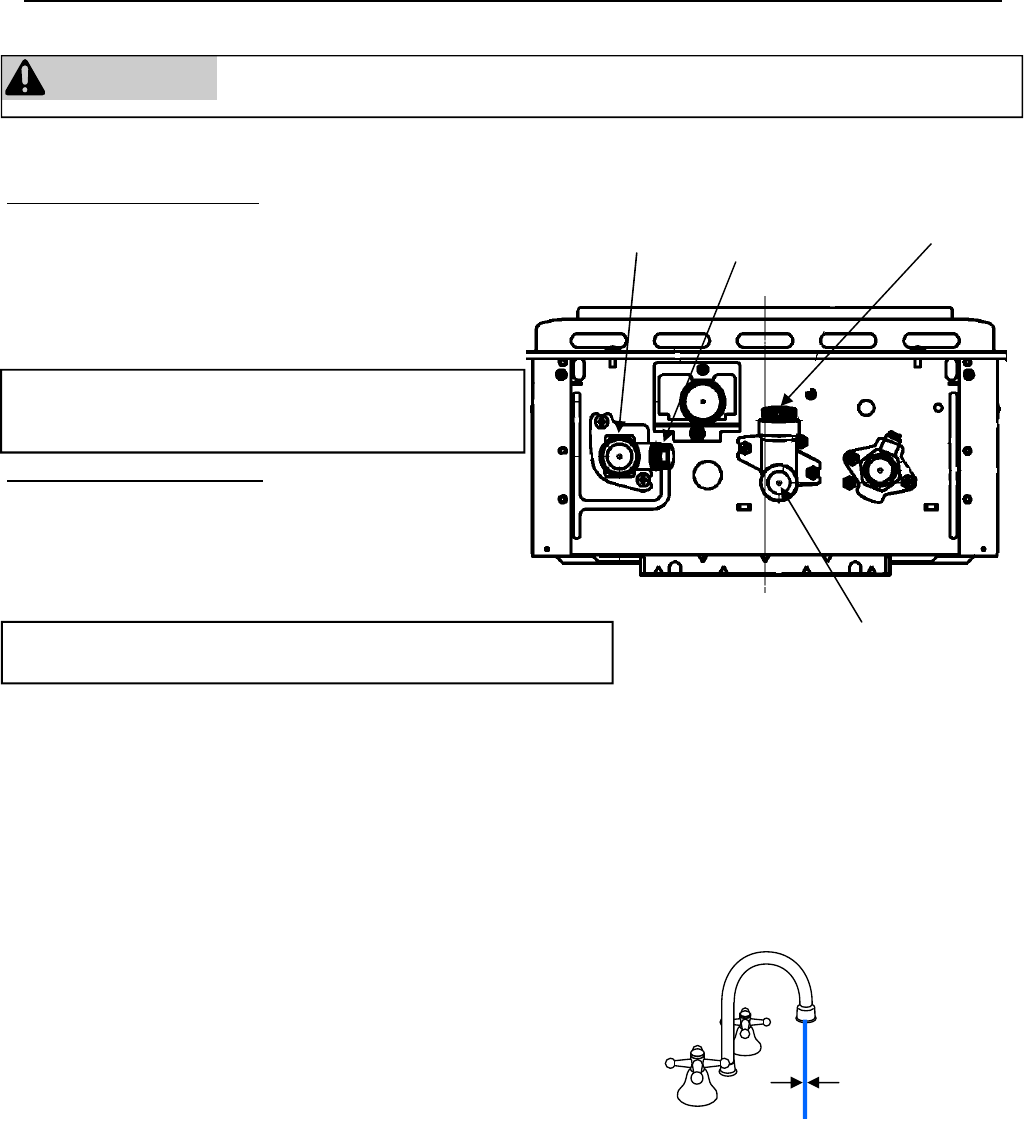
If the water heater is not going to be used during a period of possible freezing weather, it is recommended that the
water inside the water heater be drained.
Freeze Protection
Manual draining of the water heater
WARNING To avoid burns, wait until the equipment cools down before draining the water. The
water in the appliance will remain hot after it is turned off.
To manually drain the water:
1. Shut off cold water supply and gas supply.
2. Turn off the temperature controller.
3. Disconnect the power to the water heater.
4. Open hot water drain plug at the hot water outlet.
5. Remove water filter to drain the cold water.
To resume normal operation:
1. Confirm that all water drain plugs are removed, that
the gas supply is turned off, and that all taps are
closed.
2. Screw in the hot water drain plug.
3. Screw in the water filter in the cold water inlet.
4. Open the cold water supply.
5. Open a tap and confirm that water flows, and then close.
6. Turn on the power.
7. After confirming that the temperature controller is off, turn on
the gas supply.
8. Turn on the temperature controller.
Running a low volume of water through the water heater to prevent freezing
If the temperature exceeds the ability of the water heater to freeze
protect itself, or if power is lost, the following steps may prevent the
water heater and external piping from freezing. (Units connected with
MSA or EZConnect should be drained to prevent freezing if not in use.)
1. Turn the water heater off.
2. Close the gas supply valve.
3. Reduce the flow to about 0.1 gal/min or to where the stream is about
0.2 inches thick.
When the water heater or external piping has frozen
1. Do not operate the water heater if it or the external piping is frozen.
2. Close the gas and water valves and turn off the power.
3. Wait until the water thaws. Check by opening the water supply valve.
4. Check the water heater and the piping for leaks.
HOT
COLD
ON!
0.1 gal/min or
about 0.2 inch
thick
* Use a wrench or other
tool to unscrew the hot
water drain plug.
Water
filter
Hot water
outlet
Hot water
drain plug *
Cold water
inlet
If an isolation kit is installed, remove the drain caps on
both isolation valves and open both valves above the
caps (blue and red valve handles).
If the isolation kit was used to drain the unit, replace the drain caps
and close both isolation valves (blue and red valve handles).
VB Series Indoor LS Manual 23
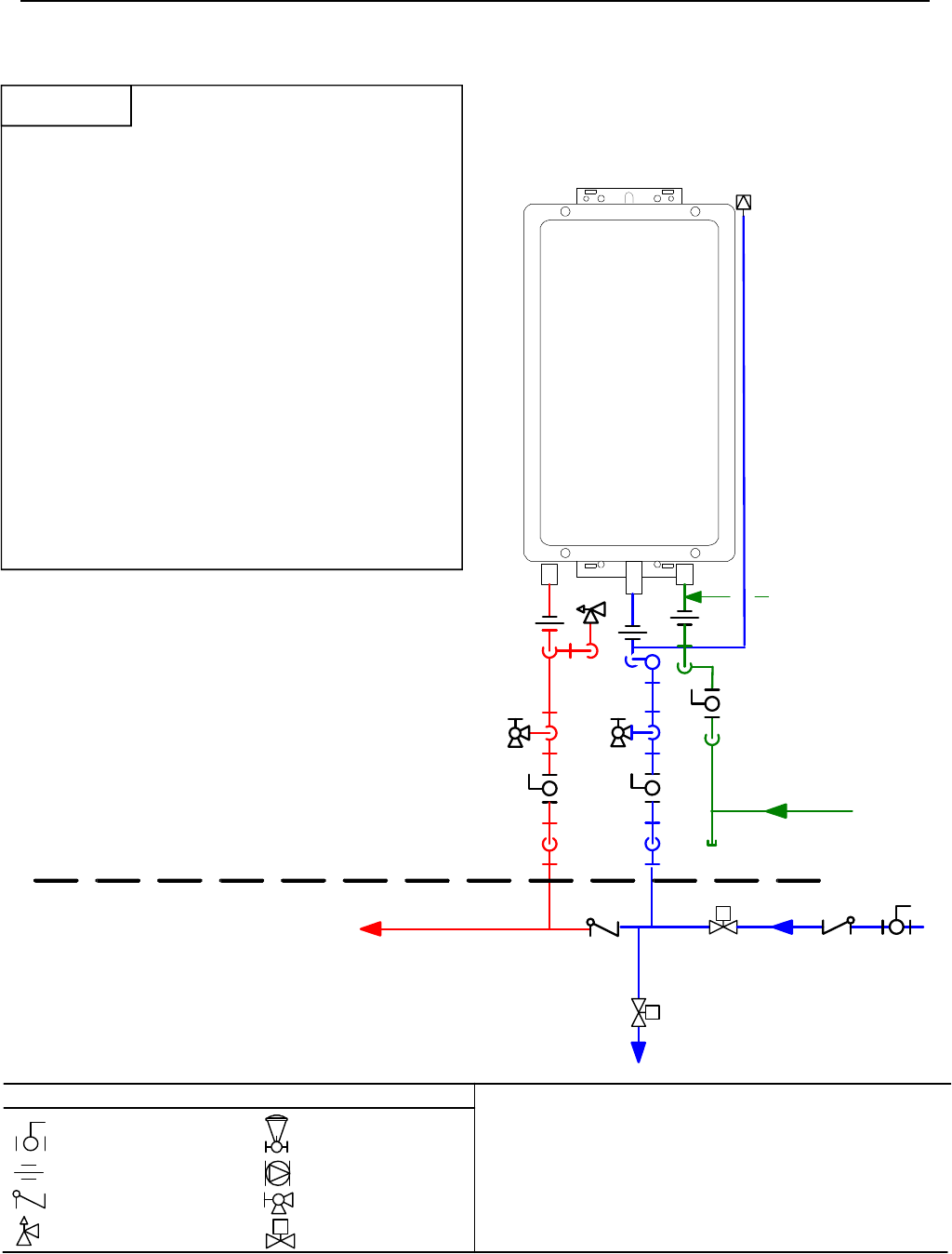
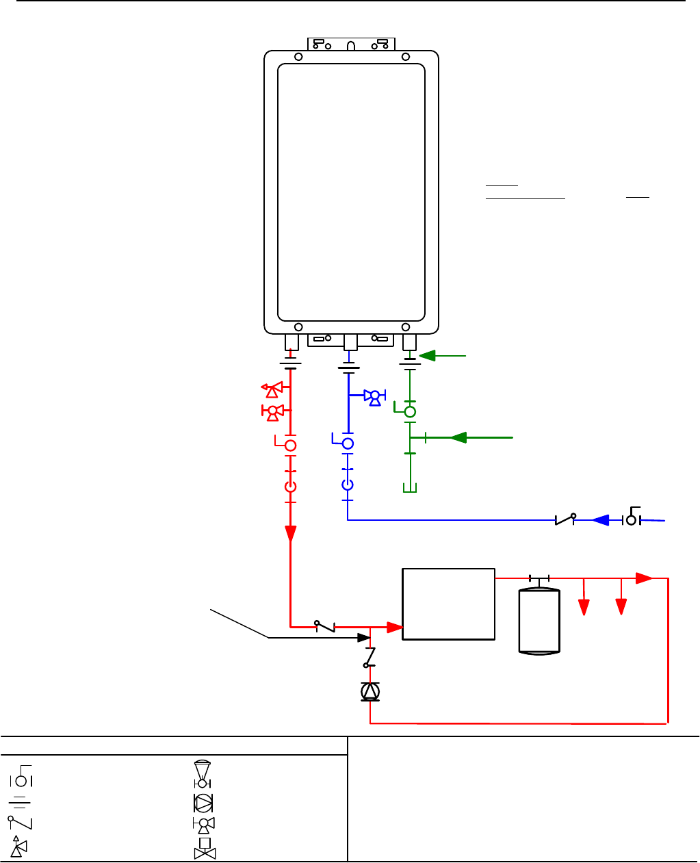
Pressure Relief Valve
3/4" Ball Valve
3/4" Union
Check Valve
S
Pressure Regulator
Circulating Pump
Solenoid Valve
Boiler Drain Valve
KEY
GasSupply
Minimum3/4"
ColdWater
SupplyLine
Minimum 3/4" Hot Water
Supply Line
S
1/2" Minimum
Normally Open
Solenoid Valve
3/4" Minimum
Normally Closed
Solenoid Valve
Route to Floor Drain
Vacuum
Breaker
NOTE:
ALL pipe and fittings shown below dashed line
should be located inside home or building
structure.
NOTE:
Heat trace ALL water pipe and fittings located
outside home (attic, crawl space) or building
structure. (ALL water pipe and fittings shown
above the dashed line in the drawing.)
Rinnai
Water Heater
3/4"GasConnection
S
The vacuum breaker line should be located
inside the building structure.
This is not an engineered drawing. It is intended only as a guide and not
as a replacement for professionally engineered project drawings. This
drawing is not intended to describe a complete system. It is up to the
contractor/engineer to determine the necessary components and
configuration of the particular system being installed. This drawing does
not imply compliance with local building code requirements. It is the
responsibility of the contractor/engineer to ensure installation is in
accordance with all local building codes. Confer with local building
officials before installation.
Freeze Protection Piping
Warranty does not cover damage due to freezing.
In the event of a power failure at temperatures below
freezing the water heater should be drained of all
water to prevent freezing damage.
The unit may be drained manually. However, Rinnai
highly recommends that drain down solenoid valves
be installed that will automatically drain the unit if
power is lost. Rinnai also recommends the installation
of a surge protector with terminals which allows the
solenoid valves to operate if the unit is disabled due to
an error code.
When the electrical power to the water heater fails, the
3/4” solenoid valve closes (stopping the flow of water
into the heater) and the 1/2” solenoid valve opens
(allowing the water heater and associated piping to
drain. Ensure that you run the drain for the solenoids
to the outside environment to prevent discharging
water inside the building causing water damage).
NOTICE
24 VB Series Indoor LS Manual
Recommended Piping for Basic Installation
GasSupply
3/4"ColdWaterSupplyLine
3/4" Hot Water Supply Line
Rinnai
Water Heater
Rinnai
Equipment List
Rinnai
Water Heaters
RIK-KIT (Optional)
(3/4" Fittings Include:
2 Unions, 2 Ball Valves,
2Drain Valves and
1 Pressure Relief Valve.)
QTY
1
1
3/4"GasConnection
For Building Fixtures
Pressure Relief Valve
3/4" Ball Valve
3/4" Union
Check Valve
S
Pressure Regulator
Circulating Pump
Solenoid Valve
Boiler Drain Valve
KEY
This is not an engineered drawing. It is intended only as a guide and not
as a replacement for professionally engineered project drawings. This
drawing is not intended to describe a complete system. It is up to the
contractor/engineer to determine the necessary components and
configuration of the particular system being installed. This drawing does
not imply compliance with local building code requirements. It is the
responsibility of the contractor/engineer to ensure installation is in
accordance with all local building codes. Confer with local building
officials before installation.
VB Series Indoor LS Manual 25
Recommended Piping for Circulation Systems
Pressure Relief Valve
3/4" Ball Valve
3/4" Union
Check Valve
S
Pressure Regulator
Circulating Pump
Solenoid Valve
Boiler Drain Valve
KEY
Minimum 3/4" Cold Water Supply Line
Electric Water
Heater
Building
Fixtures
Building Supply
ExpansionTank
GasSupply
QTY
1
1
Rinnai
Water Heater
Rinnai
Equipment List
Rinnai
Water Heaters
RIK-KIT (Optional)
(3/4" Fittings Include:
2 Unions, 2 Ball Valves,
2 Drain Valves and
1 Pressure Relief Valve.)
3/4"GasConnection
Tank Water Heater to be Sized for
Heat Loss of Circulation Loop.
For this application:
Pump should be controlled by an Aqua-
stat, Timer or Combination Aquastat and
Timer.
Pump to be sized to maintain circulation
loop temperature.
The pump should be sized to overcome
t
he pressure loss through the tank water
heater, and supply and return plumbing.
Reference the Rinnai Hot Water System
Design Manual, Pump Sizing for Circula-
t
ion.
Pump to be of bronze or stainless
construction.
This is not an engineered drawing. It is intended only as a guide and not
as a replacement for professionally engineered project drawings. This
drawing is not intended to describe a complete system. It is up to the
contractor/engineer to determine the necessary components and
configuration of the particular system being installed. This drawing does
not imply compliance with local building code requirements. It is the
responsibility of the contractor/engineer to ensure installation is in
accordance with all local building codes. Confer with local building
officials before installation.
IMPORTANT: Connect the building
return line to the hot water supply line
as close as possible to the Rinnai Water
Heater.
NOTE:
For residential and commercial
applications, this piping arrange-
ment maintains full warranty.
NOTE:
For residential and commercial
applications, this piping arrangement
maintains full warranty.
26 VB Series Indoor LS Manual
Venting Instructions
• This water heater is a direct vent water heater and
therefore is certified and listed with the vent
system. You must use vent components that are
certified and listed with the water heater model.
• Do not combine vent components from different
manufacturers.
• The vent system must vent directly to the outside
of the building and use outside air for combustion.
• Venting should be as direct as possible with a
minimum number of pipe fittings.
• Avoid dips or sags in horizontal vent runs by
installing supports per the vent manufacturer’s
instructions.
• Support horizontal vent runs every four feet and all
vertical vent runs every six feet or in accordance
with local codes.
• Vent diameter must not be reduced.
• Do not connect the venting system with an existing
vent or chimney.
• Do not common vent with the vent pipe of any
other water heater or appliance.
• Vent connections must be firmly pressed together
so that the gaskets form an air tight seal.
• RL75i, RL94i: The vent piece connected to the
water heater must be secured with one self-tapping
screw.
• Refer to the instructions of the vent system
manufacturer for component assembly instructions.
• If the vent system is to be enclosed, it is suggested
that the design of the enclosure shall permit
inspection of the vent system. The design of such
enclosure shall be deemed acceptable by the
installer or the local inspector.
Condensate
Condensate formation can occur in high efficiency
direct vent appliances. To prevent condensate
damage follow these instructions.
Intake / Exhaust Guidelines Refer to the specific instructions on your vent product for additional
installation requirements.
NOTICE
Provisions must be made to prevent the condensate
from entering the water heater. Without proper
drainage or disposal, condensate will damage the heat
exchanger.
Do not plug or cap the integrated condensate line.
Without proper drainage or disposal, condensate will
damage the water heater.
WARNING
The condensate trap must be primed before operation
to prevent exhaust gases from entering the building.
NOTICE
If it becomes necessary to access an enclosed vent
system for service or repairs, Rinnai is not responsible
for any costs or difficulties in accessing the vent
system. Warranty does not cover obtaining access to
an enclosed vent system.
• Vertical terminations must incorporate a
condensate drain and trap as close as possible to
the appliance.
• RL75i, and RL94i water heaters have an integrated
condensate collector.
• Rinnai offers a condensate trap.
• Regions of cold climate will create more
condensate in the vent system. The condensate
collector should be used in cold climates.
• Use only vent that is approved and identified as
acceptable for your particular model.
• Do not use PVC, CPVC, ABS or galvanized
material to vent this appliance.
• Slope the venting toward the appliance according to
the vent manufacturers installation instructions.
• All condensate must drain and be disposed of per
local codes.
• Use only PVC or CPVC pipe for the condensate
drain line.
• The condensate drain pipe should be as short as
possible and have a downward pitch.
• Do not connect the condensate drain pipe directly
to the rain sewer.
• The condensate drain pipe (along its entire length)
must be at least the same diameter as the drain
line, (3/8 inch NPT).
• The end of the condensate drain pipe should be
open to the atmosphere. The end should not be
under water or other substances.
• Do not connect the condensate drain line with an
air conditioning evaporator coil drain.
• To minimize freezing of the condensate, run the
condensate drain line through an interior wall or
between insulation and an interior wall.
• The condensate collector should be used for all
hydronic heating applications.
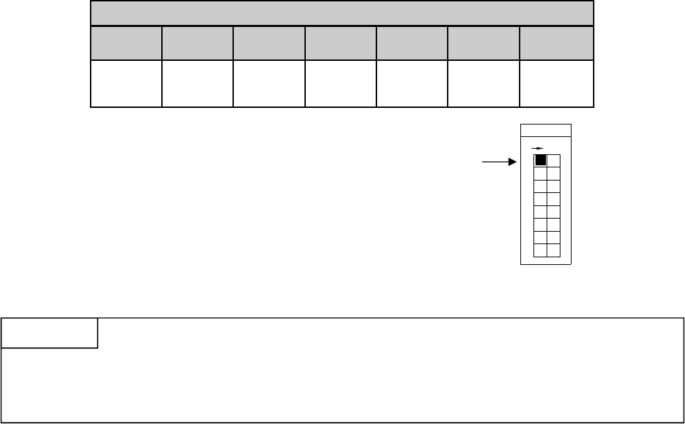
VB Series Indoor LS Manual 27
Example: If you have one elbow then your maximum vent length is 35 feet (10.7 m). If your actual length is
greater than 15 ft (4.6 m) then move switch no. 1 (SW1) to OFF.
Maximum Vent Length
1. Determine the number of 90 degree elbows in the vent system. (Two 45 degree elbows count as one 90
degree elbow. On the R98 models each one foot of semi rigid flex duct used in the air intake length is
equivalent to one 90 degree elbow.)
2. Refer to the table to find the maximum vent length based on the number of elbows.
3. Follow the applicable note.
If you have a longer vent length, switch no. 1 is required to be in the OFF position. This ensures the water
heater will run properly. Blocked flue error codes and shutdowns may result if switch no. 1 is not in the correct
position. On the RL94i, the maximum water flow capacity will be reduced by about 10% when switch no. 1 is
OFF.
NOTICE
Number of 90° Elbows
0 1 2 3 4 5 6
41 ft 1
(12.5 m)
35 ft 2
(10.7 m)
29 ft 3
(8.8 m)
23 ft 4
(7.0 m)
17 ft 4
(5.2 m)
11 ft 4
(3.4 m)
5 ft 4
(1.5 m)
Notes 1234
1 If the length is greater than 21 ft (6.4 m) then move
switch no. 1 (SW1) to OFF.
2 If the length is greater than 15 ft (4.6 m) then move
switch no. 1 (SW1) to OFF.
3 If the length is greater than 9 ft (2.7 m) then move
switch no. 1 (SW1) to OFF.
4 Move switch no. 1 (SW1) to OFF.
Switch No.
F
O
F
8
5
7
6
4
3
ON
1
2
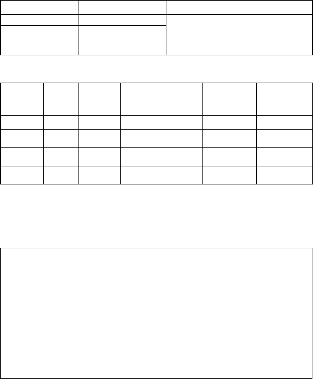
28 VB Series Indoor LS Manual
Vent Products
Manufacturer Product Parts
Rinnai/Ubbink Rolux Vent System
Heat-Fab Saf-T Vent SC system
Metal-Fab Corr/Guard Vent/Air
Intake System
Refer to the manufacturer’s technical literature for
specific part numbers and instructions.
Listed and Tested Vent Products for
RL75i ........................ REU-VB2528FFUD-US
RL94i ........................ REU-VB2735FFUD-US
Listed and Tested Vent Products for
Manufacturer Product Appliance
Adapter
Vertical
Termination
Horizontal
Termination
Horizontal
Concentric
Termination
Heat-Fab Saf-T Vent 9401AMTK 5400CI 9492 NA
Z-Flex Z-Vent 2SVSNA04.5 2SVSRCF4 2SVSTPX4 NA
ProTech
Systems FasNSeal FSAAU4 * FSRC4 * FSBS4 * FSDVPTB04LH *
FSDVWT4
Metal-Fab Corr/Guard 4CGOA 4CGSWC 4CGSWMCM 4CG7HT90
4CG7HT
Adjustable
Horizontal
Concentric
Termination
NA
NA
FSDVWMTP4LH,
FSEDVWMTP4LH
NA
R98LSi ..................... REU-VA3237FFU
R98LSi-ASME ......... REU-VA3237FFU-ASME
FSAAU4 - ask for FSAAU4SP (single pack)
FSRC4 - ask for FSVPK4 Variable Pitch Roof Flashing
Kit (includes rain cap FSRC4, storm collar, roof jack,
and roof flashing)
FSBS4 - ask for FSBS4SP (single pack)
FSDVPTB04LH - ask for FSDVWMT04LH Kit (includes
direct vent pass through FSDVPTB04LH, bird screen,
exterior and interior mounting plates, appliance
adapter, 3 foot flexible aluminum duct with 2 clamps,
and adjustable vertical length)
* When ordering from Rinnai, ask for these part numbers or kits:
Vent Manufacturer Contact Information for Installation Instructions and Parts Lists:
Heat-Fab
Telephone: 800-772-0739
Fax: 413-863-4803
E-mail: custsvc@heat-fab.com
Web Site: www.heatfab.com
Rinnai/Ubbink
Telephone: 800-621-9419
Fax: 678-829-1666
Web Site: www.rinnai.us
Metal-Fab Inc.
Telephone: 800-835-2830
316-943-2351
Fax: 316-943-2717
E-mail: info@mtlfab.com
Web Site: www.metal-fabinc.com
ProTech Systems, Inc.
Telephone: 800-766-3473
518-463-7284
Fax: 518-463-5271
E-mail: support@protechinfo.com
Web Site: www.protechinfo.com
Z-Flex
Telephone: 800-654-5600
Fax: 888-889-3539
E-mail: sales@z-flex.com
Web Site: www.novaflex.com
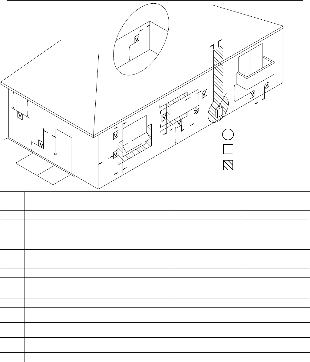
VB Series Indoor LS Manual 29
Flue Terminal Clearances (ANS Z21.10.3, CSA 4.3)
INSIDE
CORNER DETAI L
FIXED
CLOSED
OPERABLE
FIXED
CLOSED
OPERABLE
B
B
B
A
J
BM
C
F
B
B
E
D
L
G
A
H
K
I
1 A vent shall not terminate directly above a sidewalk or paved driveway that is located between two single family dwellings and serves
both dwellings.
2 Permitted only if veranda, porch, deck, or balcony is fully open on a minimum of two sides beneath the floor.
∗ For clearances not specified in ANSI Z223.1/NFPA 54 or CSA B149.1, clearances are in accordance with local installation codes and the
requirements of the gas supplier.
Clearance to opposite wall is 24 inches (60 cm) for Canada and US.
X
V
AIR SUPPLY INLET
VENT TERMINAL
AREA WHERE
TERMINAL IS NOT
PERMITTTED
Ref Description Canadian Installations US Installations
A Clearance above grade, veranda, porch, deck, or balcony 12 inches (30 cm) 12 inches (30 cm)
B Clearance to window or door that may be opened 36 inches (91 cm) 12 inches (30 cm)
C Clearance to permanently closed window * *
D
Vertical clearance to ventilated soffit, located above the terminal
within a horizontal distance of 2 feet (61 cm) from the center line
of the terminal
* *
E Clearance to unventilated soffit * *
F Clearance to outside corner * *
G Clearance to inside corner * *
H Clearance to each side of center line extended above meter/
regulator assembly
3 feet (91 cm) within a height
15 feet (4.5 m) above the
meter/regulator assembly
*
I Clearance to service regulator vent outlet 36 inches (91 cm) *
J Clearance to nonmechanical air supply inlet to building or the
combustion air inlet to any other appliance 36 inches (91 cm) 12 inches (30 cm)
K Clearance to a mechanical air supply inlet 6 feet (1.83 m) 3 feet (91 cm) above if within
10 feet (3 m) horizontally
L Clearance above paved sidewalk or paved driveway located on
public property 7 feet (2.13 m) 1 *
M Clearance under veranda, porch, deck, or balcony 12 inches (30 cm) 2 *
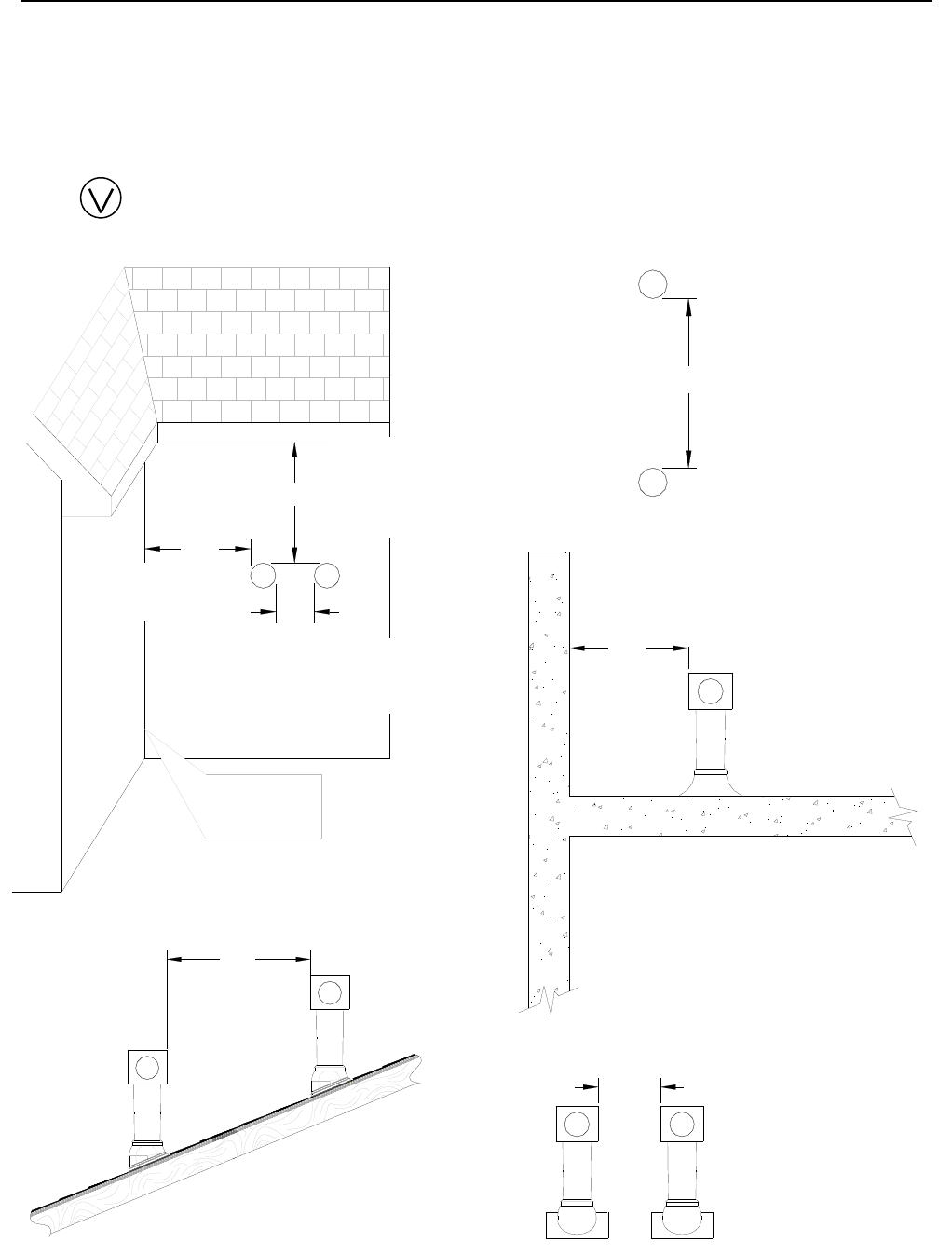
30 VB Series Indoor LS Manual
24"
V
Additional Clearances - Vent Terminal
Local codes supersede these clearances.
• Avoid termination locations near a dryer vent.
• Avoid termination locations near commercial cooking exhaust.
• For VA3237 air intake position, follow the ANS Z21.10.3 ● CSA 4.3 requirements on the previous page.
60"
V
V
(1.52 m) between
Rinnai terminals
at different levels
12"
12"
36"
INSIDE
CORNER
VV
(0.91 m) to ventilated
or unventilated soffit
or eve vent; or to a
deck or porch
(0.30 m ) to an
inside corner
(0.30 m) between
Rinnai terminals at
same level
(0.61 m) to wall or parapet
(0.30 m) between
Rinnai terminals at
same level
12"
V V
(1.52 m) vertically
between Rinnai terminals
V
60"
V
Vent terminal (represents concentric vent terminal or VA3237 exhaust only vent terminal)
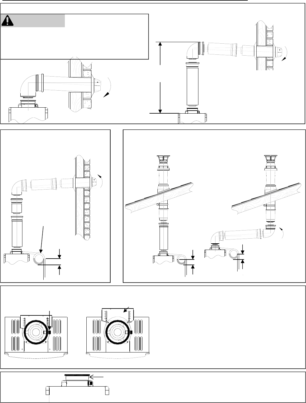
VB Series Indoor LS Manual 31
Flue Installation - Concentric Venting (RL75i, RL94i)
3 in (75 mm)
minimum
Condensate
Trap
Vertical Termination
(condensate collector must be used in all installations)
3 in (75 mm)
minimum
3 in (75 mm)
minimum
Horizontal Termination using
the Condensate Collector
3 in (75 mm)
minimum
Condensate
Trap
To adjust the condensate collector position or to
replace the female vent top with a male vent top:
1. Loosen the 4 screws at the rear bracket
2. Slide the bracket away from the female vent top.
3. Remove the 4 screws attaching the female vent
top to the water heater.
4. Lift up the female vent top and reposition as
desired (or replace with a male vent top).
5. Install the 4 screws at the vent top and tighten the
4 screws at the bracket.
Secure the first vent component to the water heater
with one self-tapping screw at the hole located above
the condensate collector.
Bracket
Condensate Collector
Securing Screw
Horizontal Termination without using the Condensate Collector
Maximum Height *
5 feet (1.52 m) Regions of cold climate will create
more condensate in the vent system.
The condensate collector should be
used in cold climates.
If more than one elbow is used in the
vertical section the condensate
collector must be used.
* The condensate collector must be used
in horizontal terminations if a vertical rise
in the vent system exceeds 5ft.
WARNING
If the condensate collector is not used, the drain pipe
must be capped to prevent exhaust gases and
condensate from entering the building. The cap is
supplied on the appliance.
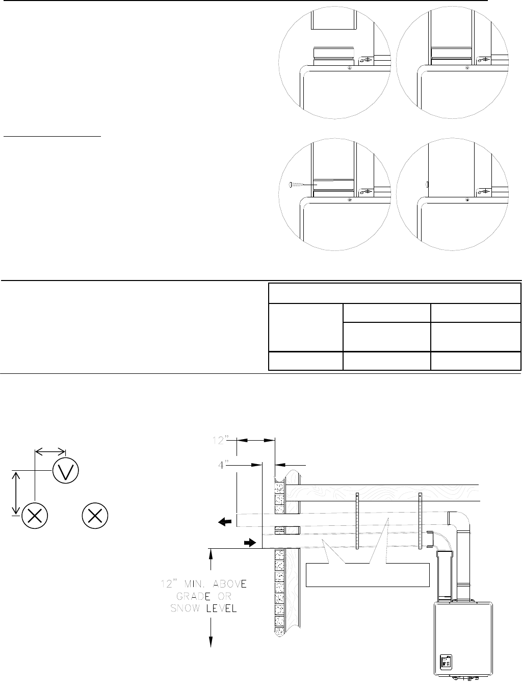
32 VB Series Indoor LS Manual
Air Intake Assembly
The air intake system consists of a field supplied 4
inch diameter stainless steel, Schedule 40 PVC, ABS
or CPVC pipe. A maximum 6 feet of semi-rigid
flexible aluminum ducting can also be used. Foil
wrapped dryer vent and cell core products are not
authorized.
The air intake has a zero clearance to combustibles.
Air Intake Connection
1. Drill 2 small holes at the end of the air intake
pipe.
2. Slide the pipe over the air intake terminal.
3. Using a level, ensure the pipe is straight up and
down.
4. With self tapping screws, attach the pipe to the air
intake terminal.
5. Apply a bead of silicone around the pipe and air
intake terminal, ensuring an air tight connection.
Exhaust Pipe Assembly
Refer to the manufacturer’s installation instructions for
the specific exhaust vent system.
Venting Clearances to Combustibles
Vent Size
Enclosed Unenclosed
Horizontal & Horizontal &
4" (102 mm) 4" (102 mm) 1" (26 mm)
4
3
12
COMBUSTION AIR /
INTAKE
EXHAUST
SLOPE INTAKE AND EXHAUST
TOWARD OUTSIDE TERMINATION
MINIMUM 1/4" PER FOOT
Horizontal Terminations
The air intake must be located in relation to the exhaust as shown below. The air intake must angle 1/4 inch per
foot to the termination to prevent entry of rain.
Flue Installation (R98LSi, R98LSi-ASME)
8”
6”
Intake
Optional
Intake
Vent
The vent termination and air
intake must be in the same
pressure zone and face the
same direction.
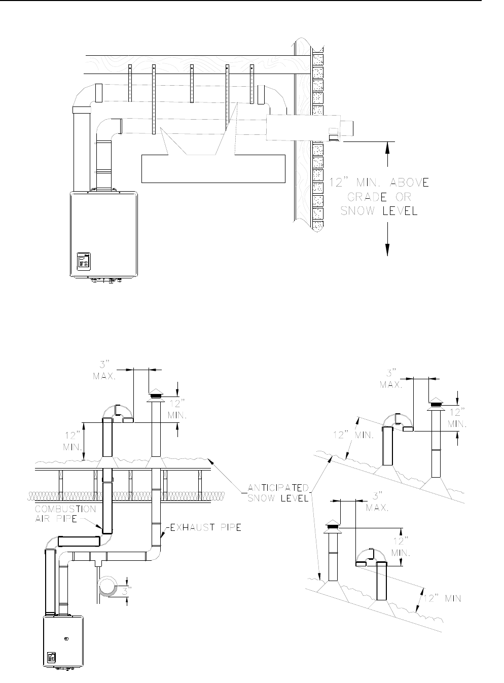
VB Series Indoor LS Manual 33
Vertical Terminations
The air intake requires a return bend or two 90º elbows to prevent entry of rain.
SLOPE INTAKE AND EXHAUST
TOWARD OUTSIDE TERMINATION
MINIMUM 1/4" PER FOOT
Horizontal with Concentric Termination
Flue Installation (R98LSi, R98LSi-ASME)
The vent termination and air intake must be in the same pressure zone.
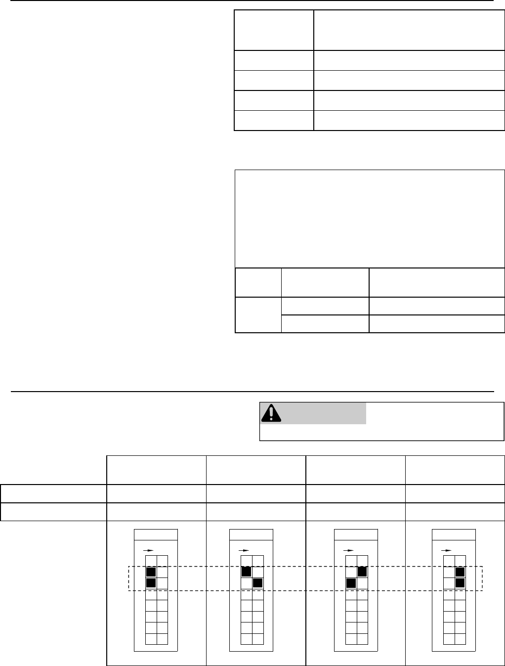
34 VB Series Indoor LS Manual
High Altitude Installations
0-2000 ft
(0-610 m)
2001-5200 ft
(610-1585 m)
5201-7700 ft
(1585-2347 m)
7701-10200 ft
(2347-3109 m)
Switch No. 2 OFF OFF ON ON
Switch No. 3 OFF ON OFF ON
Set switches 2 and 3 to the values shown in table
below for your altitude. The default setting for the
appliance is 0-2000 ft (0-610 m) with switches No. 2
and No. 3 in the OFF position.
Connecting Multiple Water Heaters
The EZConnect™ cable is an optional accessory
that connects 2 water heaters and allows them to
function as one hot water source.
The MSA-2M and MSA-2S packs are optional
accessories that connect 2 to 5 water heaters
and allow them to function as one hot water
source.
Refer to the instructions that come with the
accessory for complete installation information.
Number of
Connected
Water Heaters:
Accessories Necessary:
2 (1) EZConnect™ Cable or (1) MSA-2M
3 (1) MSA-2M and (1) MSA-2S
4 (1) MSA-2M and (2) MSA-2S
5 (1) MSA-2M and (3) MSA-2S
Guidelines
• Do not install both the EZConnect™ and the
MSA packs because they are not designed to
operate together.
• Water heaters connected with the
EZConnect™ Cable or the MSA-2M and MSA-
2S packs cannot be used for the bath fill
function.
• Water heaters should be installed less than 18
inches apart so that the cables will reach
between units and to prevent temperature
fluctuations (cold water sandwich effect) when
the water is shut off and turned back on.
• Temperature settings can only be changed on
the controller for the primary unit. (This
changes the temperature on all units within the
MSA or EZConnect™ system.)
WARNING DO NOT adjust the other
switches unless specifically
instructed to do so.
Switch No.
F
O
F
8
5
7
6
4
3
ON
1
2
Switch No.
F
O
F
8
5
7
6
4
3
ON
1
2
Switch No.
F
O
F
8
5
7
6
4
3
ON
1
2
Switch No.
F
O
F
8
5
7
6
4
3
ON
1
2
Model Number of units
in standby
Position of switch No. 5 in
bank of 6 switches
RL75,
RL94
1 ON
2 OFF (default)
Activation Options for EZConnect™
One unit in standby allows for quicker activation time with
flow rates within the capacity of a single unit.
Two units in standby allows for quicker delivery temperature
for flow rates requiring both units.
Applicable for the RL75 and RL94 models only.
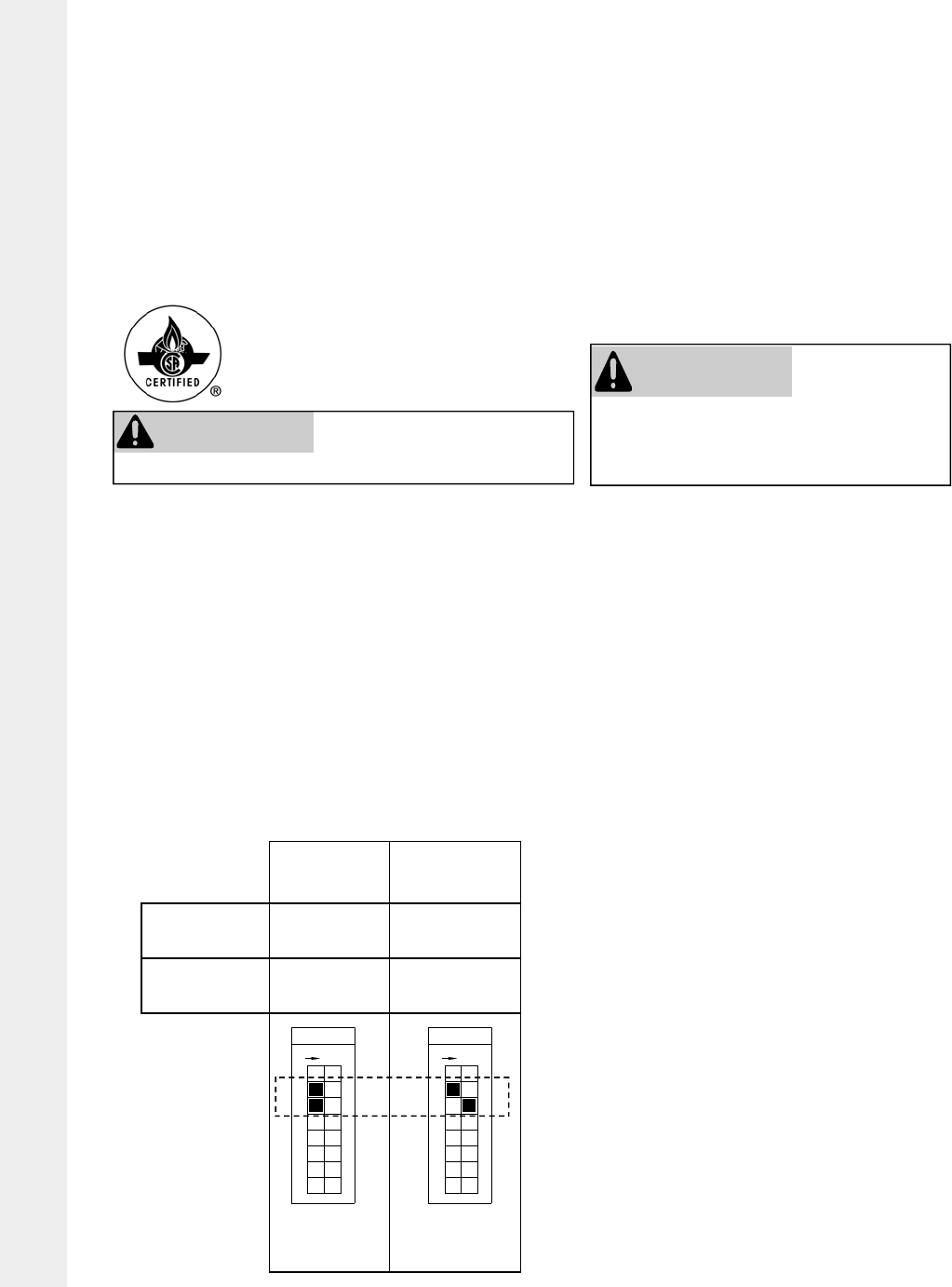
VB Series Indoor LS Manual 35
The conversion shall be carried out
by a manufacturer’s authorized rep-
resentative, in accordance with the
requirements of the manufacturer,
provincial or territorial authorities
having jurisdiction and in accordance
with the requirements of the CAN/
CGA-B149.1 or CAN/CGA-B149.2
Installation Codes / La conversion
sera exécuté par un représentant du
fabricant autorisé, conformément aux
conditions du fabricant, les autorités
provinciaux ou territoriaux ayant la
juridiction et conformément aux con-
ditions du CAN/CGA-B149.1 ou
CAN/CGA-B149.2 Codes d'Installa-
tion.
Switch
micro-
commutateur
0-2000 ft
(0-610 m)
2001-4500 ft
(610-1372 m)
No 2 OFF OFF
No 3 OFF ON
Switch No.
F
O
F
8
5
7
6
4
3
ON
1
2
Switch No.
F
O
F
8
5
7
6
4
3
ON
1
2
Water Heater High Altitude Installation Setting Procedure
610 - 1372 m (2001 - 4500 ft) for Canada Only / Procédure Reglage
de Chaffeau á' Haute Altitude 610 - 1372 m (2001 - 4500 ft) pour
Canada Seulement
WARNING DO NOT adjust the other
switches unless specifically
instructed to do so.
AVERTISSEMENT
NE modifiez PAS la disposition des
autres micro-commutateurs sauf sur
instructions spécifiques.
All settings/adjustments must be performed by a qualified
Service Technician / Tous reglages/ajustements doivent être
exécutés par un Technicien d'entretien qualifié.
1. Turn off the power source and gas supply to the water heater / Coupez l`alimentation de gaz et
électrique.
2. Remove the front cover from the water heater/ Enlever la couverture de devant du chauffe-eau.
3. Set the switches 2 and 3 to the values shown in the table below for your altitude. The default
setting for the appliance is 0-2000 ft (0-610 m) with switches No. 2 and No. 3 in the OFF posi-
tion / Régler les micro-commutateurs 2 et 3 aux valeurs montrées dans la table au dessous
pour votre altitude. Le reglage de défaut pour l'appareil est 0-2000 ft (0-610 m) avec les commu-
tateurs No 2 et No 3 sur la position OFF.
4. Turn on the gas and power to the water heater / Ouvrez l`alimentatation de gaz et électrique.
5. Open a fixture or fixtures to flow water through the water heater at the maximum flow rate ob-
tainable (at least three gallons per minute) / Ouvrir un accessoire ou accessoires pour couler de
l'eau par le chauffe-eau au débit maximum procurable (au moins trois gallons par minute).
CANADA ONLY
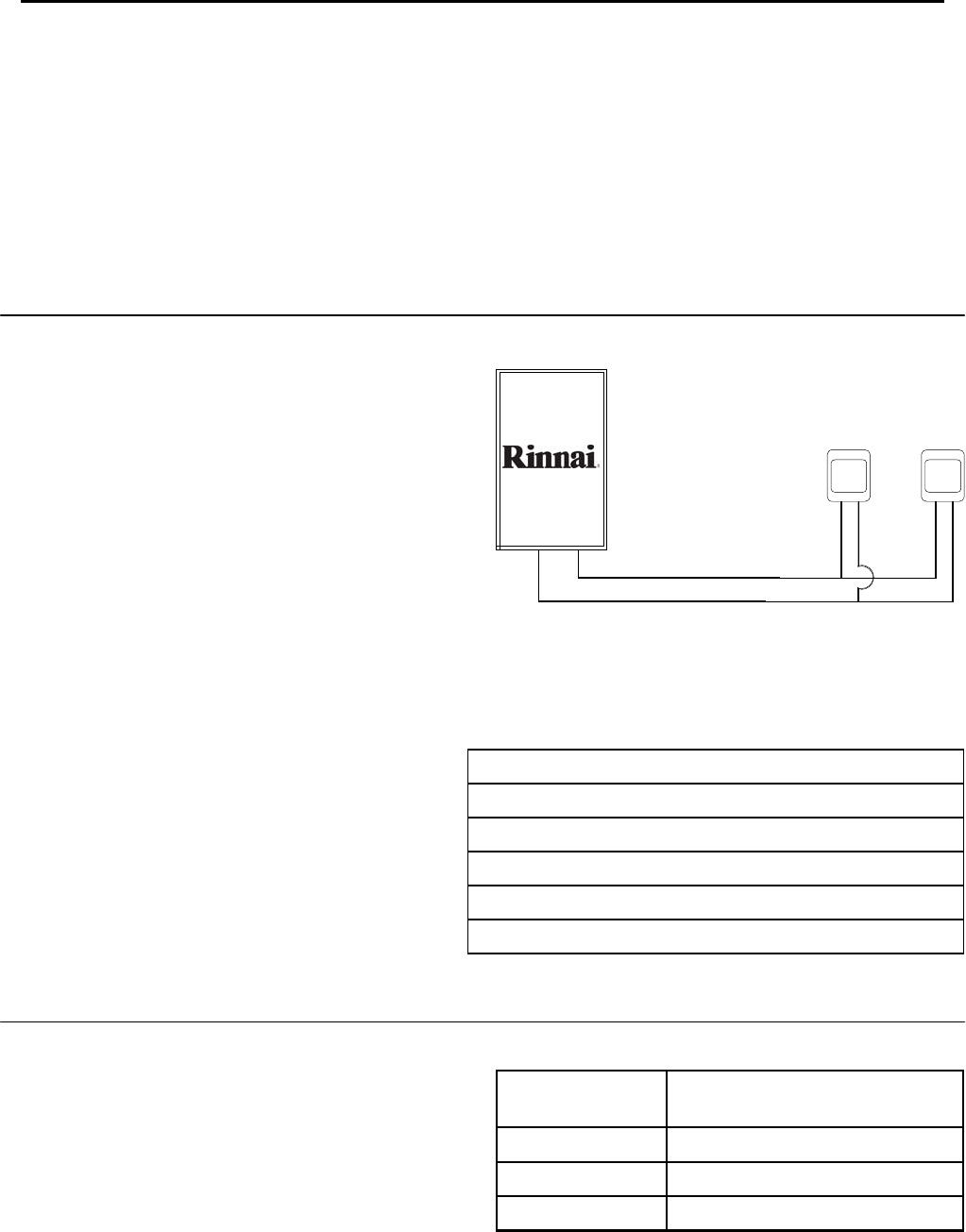
36 VB Series Indoor LS Manual
Temperature Controller Installation
• The controller should be out of reach of small
children.
• Avoid locations where the controller may become
hot (near the oven or radiant heater).
• Avoid locations in direct sunlight. The digital
display may be difficult to read in direct sunlight.
• Avoid locations where the temperature controller
could be splashed with liquids.
• Do not install in locations where it can be adjusted
by the public.
Configurations
A maximum of 4 temperature controllers, including
wired and wireless, can be installed for a water heater
or bank of water heaters. Controllers can only be
wired in parallel. Controllers cannot be wired in
series.
The 4 temperature controllers can consist of multiple
MC-91’s or MC-502RC’s but only 1 BC-100V and only
1 MC-100V.
Any one of the 5 types of controllers can be installed
by itself and still operate the water heater. All
functions will be available with the exception that the
clock function on the BC-100V will only be available if
an MC-100V is also connected.
If 4 MC-91’s are installed, simultaneously press the
Priority and On/Off buttons on the fourth controller
until a beep sounds.
The table to the right shows some of the possible
combinations of controllers.
Cable Lengths and Size
The cable for the temperature controller should be a
non-polarized two-core cable with a minimum gauge
of 22 AWG. The maximum cable length from each
controller to the water heater depends on the total
number of wired controllers connected to the water
heater.
MC-91 + MC-91 + MCC-91 MC-502RC
MC-91 + MCC-91 + MC-502RC MC-502RC
MCC-91 + MC-502RC + BC-100V MC-100V
MC-91 + MC-502RC + BC-100V MC-100V
MC-91 + MC-91 + MC-502RC BC-100V
MC-91 + MC-502RC + MC-502RC MC-100V
+
+
+
+
+
+
Number of Wired
Controllers
Maximum Cable Length for each
Controller to Water Heater
1 328 ft (100 m)
2 164 ft (50 m)
3 or 4 65 ft (20 m)
Location
Controllers
Wire controllers in parallel
Indoor models have their controller built into the front panel. A kit is available that allows the integrated controller
to be removed and used as a remote controller. Additional controllers can also be installed.
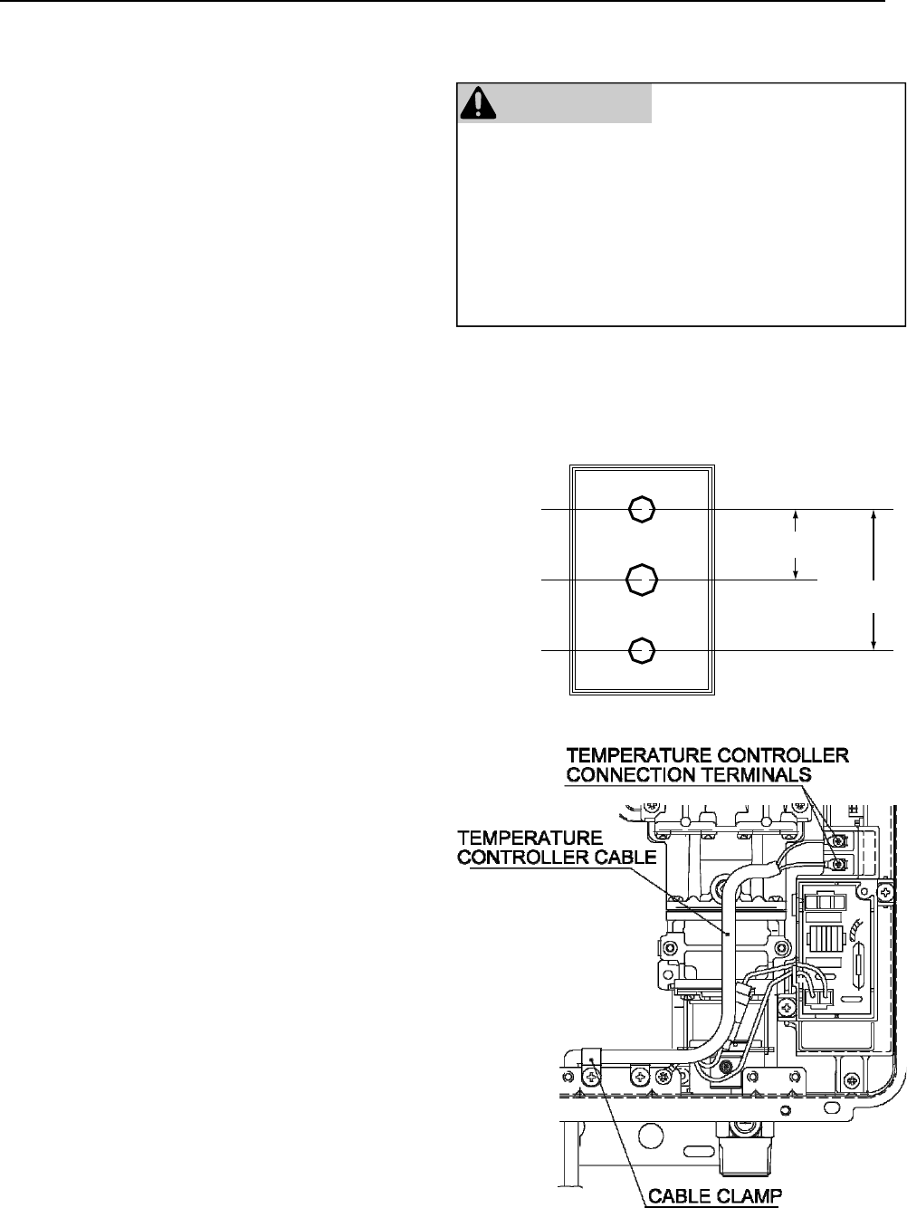
VB Series Indoor LS Manual 37
Temperature Controller Installation
1. Determine a suitable location for the
controller.
2. Make three holes in the wall as shown.
3. Run the cable between the controller and the
Rinnai water heater or the controller and the
other controller.
4. Remove the face plate from the temperature
controller using a screwdriver.
5. Connect the cable to the temperature
controller.
6. Mount the controller to the wall using the
holes drilled in step 2.
7. Disconnect the power from the Rinnai water
heater.
8. Remove the cover of the Rinnai water heater.
9. Remove the plastic cover from the PCB and
electrical connections.
10. Thread the cable through the access hole at
the base of the unit and connect the wires to
the controller terminals on the right hand side
bottom of the PCB.
11. Secure the controller cable using the clamp
provided.
12. Replace plastic cover over PCB and then
replace the cover of the Rinnai water heater.
Do not attempt to connect the temperature controllers
with the power on. There is 120 volt potential, next to
the temperature controller connections inside the unit.
Do not connect the temperature controller to the
120VAC terminals provided for the optional
solenoid drain valves.
All service and wiring should be performed by a
registered installer.
WARNING
Outline of Remote
securing screw
1-21/32"
3-5/16
"
securing screw
wiring hole
Mounting the Controller
Follow the procedure below to install MC-91 or
MCC-91 temperature controllers.
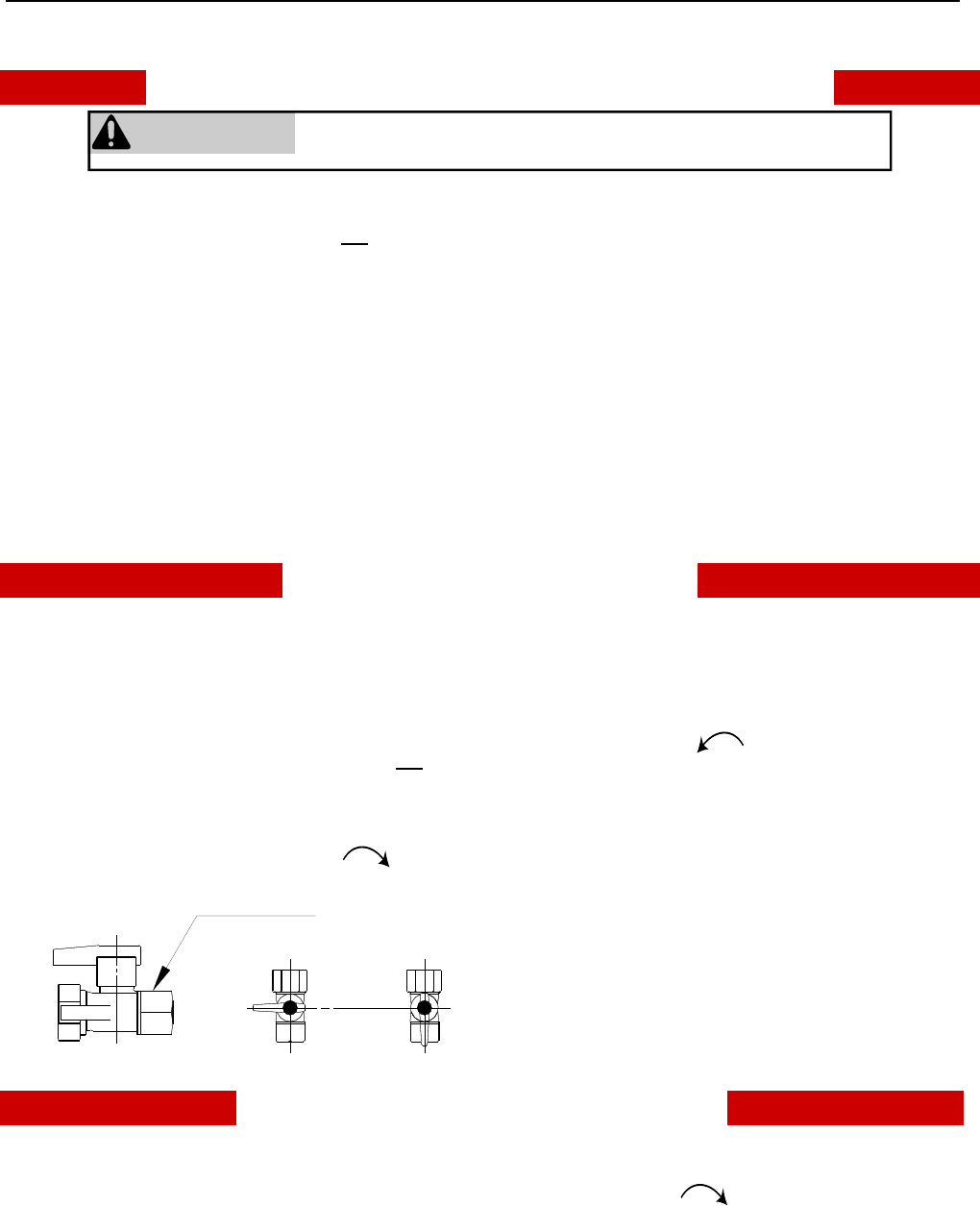
38 VB Series Indoor LS Manual
Operating Instructions
FOR YOUR SAFETY READ BEFORE OPERATING
A. This appliance does not have a pilot. It is
equipped with an ignition device which
automatically lights the burner. Do not try to light
the burner by hand.
B. BEFORE OPERATING smell all around the
appliance area for gas. Be sure to smell next to
the floor because some gas is heavier than air and
will settle on the floor.
WHAT TO DO IF YOU SMELL GAS
• Do not try to light any appliance.
• Do not touch any electric switch; do not use any
phone in your building.
• Immediately call your gas supplier from a
neighbor’s phone. Follow the gas supplier’s
instructions.
• If you cannot reach your gas supplier, call the
fire department.
C. Use only your hand to push in or turn the gas
control knob. Never use tools. If the knob will not
push in or turn by hand, do not try to repair it, call a
qualified service technician. Force or attempted
repair may result in a fire or explosion.
D. Do not use this appliance if any part has been
under water. Immediately call a qualified service
technician to inspect the appliance and to replace
any part of the control system and any gas control
which has been under water.
TO TURN OFF GAS TO APPLIANCE
1. Turn off all electric power to the appliance using
the ON/OFF button.
2. Set the thermostat to lowest setting.
3. Locate the manual gas valve on the side of the
heater. Turn the manual valve clockwise to the full
OFF position.
OPERATING INSTRUCTIONS
1. STOP! Read the safety information above.
2. Set the thermostat to lowest setting.
3. Turn off all electric power to the appliance using
the ON/OFF button.
4. This appliance is equipped with an ignition device
which automatically lights the burner. Do not try to
light the burner by hand.
5. Locate the manual gas valve on the side of the
heater. Turn the manual valve
clockwise to the full OFF position.
6. Wait five (5) minutes to clear out any gas. Then
smell for gas, including near the floor. If you smell
gas, STOP! Follow “B” in the safety information
above. If you don’t smell gas, go to the next step.
7. Turn the manual gas valve counterclockwise to the
full ON position.
8. Turn on all electric power to the appliance using
the ON/OFF button.
9. Set the thermostat to desired setting.
10. Open a hot water tap. If the appliance will not
operate, follow the instructions “To Turn Off Gas
To Appliance” and call your service technician or
gas supplier. See manual for additional
information.
CLOSE
Manual Valve
OPEN
WARNING
If you do not follow these instructions exactly, a fire or explosion
may result causing property damage, personal injury or loss of life.
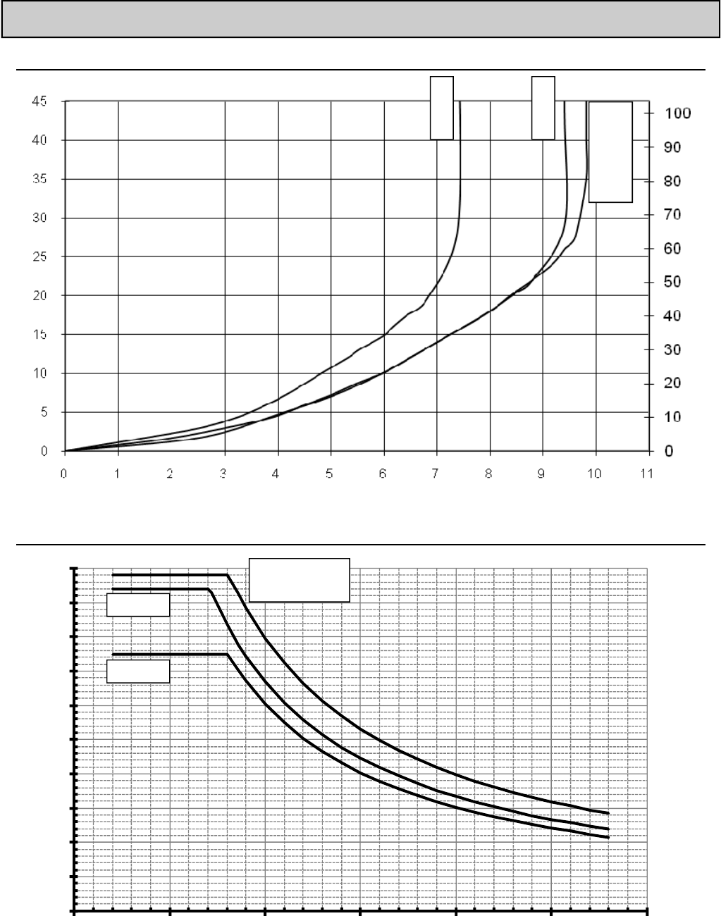
VB Series Indoor LS Manual 39
0.0
1.0
2.0
3.0
4.0
5.0
6.0
7.0
8.0
9.0
0.0
0 25507510012515
0
Technical Data
Pressure Drop Curve
Outlet Flow Data
RL94i
RL75i
R98LSi
R98LSi-ASME
RL94i
RL75i
Water Flow (gpm)
delta T - Temperature Rise (ºF)
Pressure Loss (ft head)
Water Flow (gpm)
Pressure Loss (psi)
R98LSi
R98LSi-ASME

40 VB Series Indoor LS Manual
Space Heating
If the water heater is to be used for both water (potable) heating and space heating then the following apply.
• The piping and components connected to the water heater shall be suitable for use with potable water.
• Toxic chemicals, such as used for boiler treatment, shall not be introduced into the potable water.
• The water heater shall not be connected to any heating system or components previously used with a
nonpotable water heating appliance.
• When the system requires water for space heating at temperatures higher than required for other uses, a
means such as a mixing valve shall be installed to temper the water for other uses in order to reduce the
scald hazard potential.
Temperature Setting
When using this appliance to provide domestic hot water it is recommended that the domestic hot water
temperature be reduced to acceptable temperatures in accordance with local codes. In the absence of local
codes it is recommended that the domestic hot water temperature be set to 140º F (60º C) or lower in accordance
with UPC 501.6 by using mixing valves or the temperature controller for the water heater.
Pumps
Only use pumps of brass or stainless steel construction. Do not use pumps of iron construction as they will
oxidize and clog the inlet filter on the appliance.
Pumps circulating water through the water heater must be sized to overcome the pressure loss through the water
heater, the heating system, and any additional plumbing pressure losses. The pressure drop curve based on the
water heater model is provided in this manual.
Replacement
When replacing an existing space heating application’s water heating source (boiler, tank water heater, tankless
water heater, etc.) with Rinnai water heaters, ensure that the water heaters are sized to adequately provide the
necessary BTU input for the desired space heating application. Rinnai water heaters are designed to maintain a
constant outlet temperature and will supply only the necessary amount of BTU’s to maintain that temperature.
Depending on the application the maximum BTU rating of the unit may not be achieved. Contact Rinnai’s
Applications Engineering Department for assistance at (800) 621-9419 ext. 4490.
Iron Components
Do not use Rinnai water heaters directly for space heating applications involving iron radiators or applications with
any iron components. Iron components may oxidize creating rust that will clog the inlet filter of the Rinnai water
heater.
Space heating applications are considered commercial applications for warranty purposes.
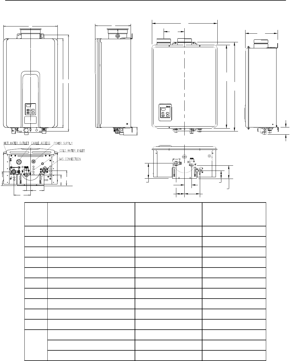
VB Series Indoor LS Manual 41
Dimensions
DIM DESCRIPTION RL75i
RL94i
in (mm)
R98LSi
R98LSi-ASME
in (mm)
A Width 14 (355.6) 18.5 (470)
B Depth * 9.6 (244.5) 9.1 (230.5)
C Height - Unit 22.9 (582) 23.6 (600)
D Height - with brackets 25.5 (648.2) 25.2 (639.8)
E Hot Water Outlet - from wall * 3.6 (91) 4.3 (110)
F Hot Water Outlet - from center 4.3 (110) 2.4 (61)
G Cold Water Inlet - from wall * 2.8 (70) 3.7 (94)
H Cold Water Inlet - from center 1.1 (27) 2.0 (52)
I Gas Connection - from wall * 3.9 (99) 2.2 (56.2)
J Gas Connection - from center 3.5 (89) 4.3 (110)
K
From base to gas connection 1.6 (40) 1.6 (40)
From base to cold connection 2.0 (50) 2.0 (50)
From base to hot connection 1.6 (41) 1.6 (41)
* This is the minimum dimension from the wall. The wall bracket is adjustable to allow an additional 1.57 inches
(40 mm).
RL75i, RL94i R98LSi, R98LSi-ASME
10.8600
L
A
C
D
EG
I
H
FJ
B
K
A
C D
B
K
E
HJ
F
GI
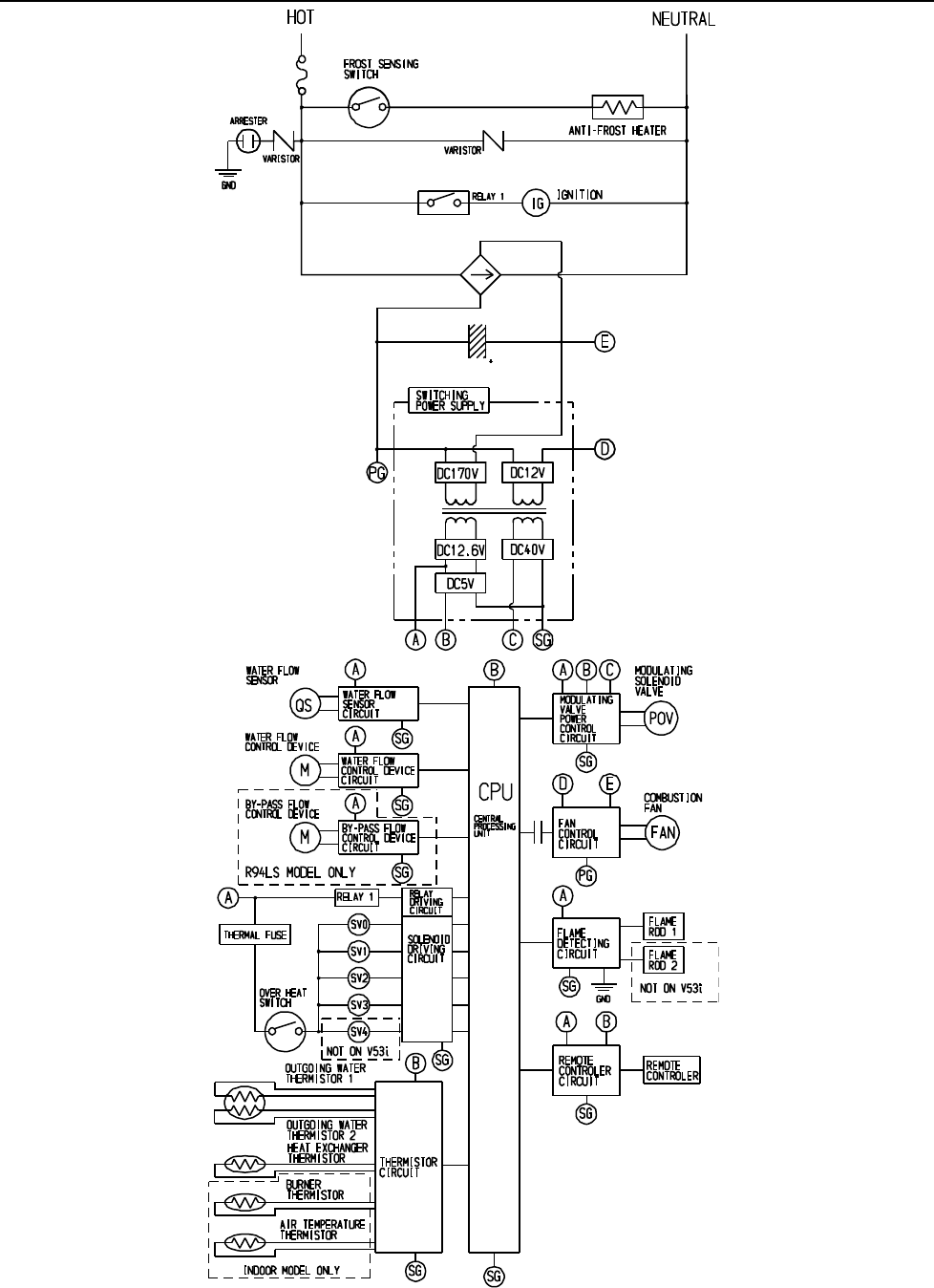
42 VB Series Indoor LS Manual
Ladder Diagram (for RL75i and RL94i)
For the R98LSi and R98LSiASME
models see the next page.
5A (FUSE)
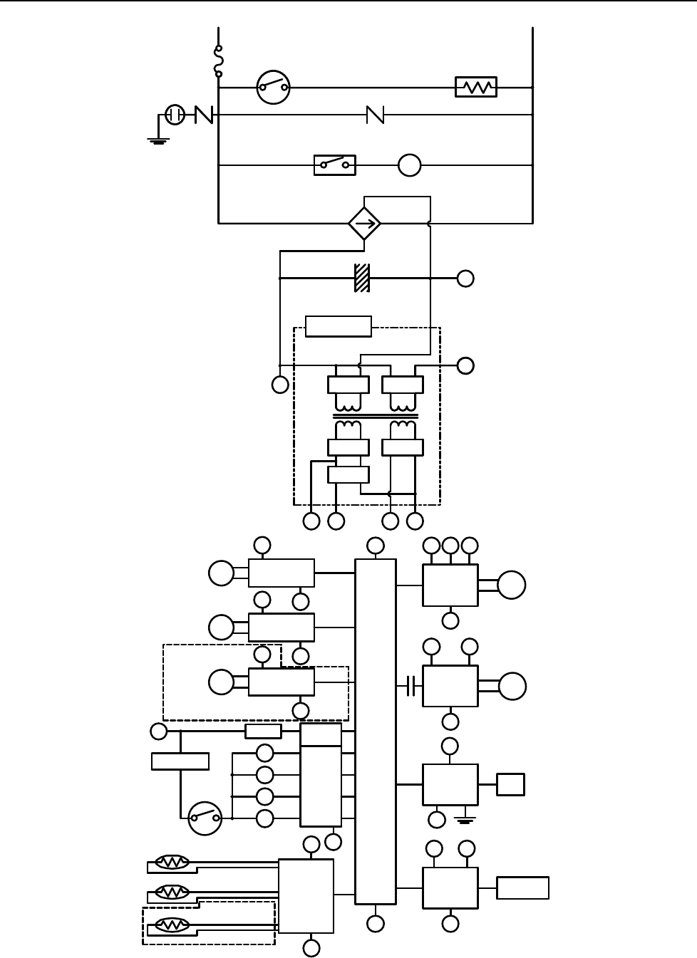
VB Series Indoor LS Manual 43
Ladder Diagram (for R98LSi and R98LSi-ASME)
RELAY 1
IG
FROST SENSING
SWITCH
ANTI-FROST HEATER
IGNITION
COMBUSTION
FAN
3A(FUSE)
HOT NEUTRAL
VARISTOR
DC12.6V
SOLENOID
DRIVING
CIRCUIT
CPU
CENTRAL
PROCESSING
UNIT
FAN
REMOTE
CONTROLLER
POV
FAN
CONTROL
CIRCUIT
BY-PASS FLOW
CONTROL DEVI CE
CIRC UIT
THERMAL FUSE
OVER HEAT
SWITCH
MODULATING
SOLENOID
VALVE
DC40V
DC5V
A B C SG
SWITCHING
POWER SUPPLY
THERMISTOR
CIRCUIT
B
SG
RELAY 1
A
WATER FLOW
SENSOR
CIRCUIT
WATER FLOW
CONTROL DEVI CE
CIRC U IT
A
SG
A
SG
SG
A
QS
SG
FR
FLAME
DETECTING
CIRCUIT
FLAME ROD
GND
SG
A
REMOTE
CONTROLLER
CIRCUIT
A B
E
PG
ABC
SG
SG
B
VARI STOR
ARRESTER
GND
SG
WATER FLOW
SENSOR
WATER FLOW
CONTROL DEVI CE
BY-PASS FLOW
CONTROL DEVICE
M
M
DC12V
DC170V
D
E
PG
SV3
SV2
SV1
SV0
RELAY
DRIVING
CIRCUI T
D
BY-PASS SERVO MODEL ONLY
OUTGOING WATER
THERMISTOR
HEAT EXCHANGER
THERMISTOR
AIR TEMPERATURE
THERMISTOR
INDOOR MODEL ONLY
MODULATING
VALVE POWER
CONTROL
CIRC UIT
44 VB Series Indoor LS Manual
What is covered?
This Warranty covers any defects in materials or workmanship when the product is installed and operated according to Rinnai
written installation instructions, subject to the terms within this Limited Warranty document. This Warranty applies only to
products that are installed correctly. Improper installation may void this Warranty. Rinnai strongly suggests that you use a
state qualified or licensed installer who has attended a Rinnai product knowledge class before installing this water heater. This
Warranty extends to the original purchaser and subsequent owners, but only while the product remains at the site of the
original installation. This Warranty only extends through the first installation of the product and terminates if the product is
moved or reinstalled at a new location.
How long does coverage last?
Limited Warranty
Warranty Information
The installer is responsible for your water heater’s correct installation.
Please complete the information below to keep for your records:
Purchased from: _________________________________________________________________
Address: _____________________________ Phone: _________________________________
_____________________________
Date of Purchase: __________________________________
Model No.: ________________________________________
Serial No.: ________________________________________
Installed by: ___________________________ Installer’s License No.: _____________________
Address: _____________________________ Phone: _________________________________
Date of Installation: __________________________________
* Note: Period of coverage is reduced to 3 years from date of purchase when used as a circulating water heater within a hot
water circulation loop, where the water heater is in series with a circulation system and all circulating water flows
through the water heater, and where an on-demand recirculation system is not incorporated.
On-demand recirculation is defined as a hot water recirculating loop or system that utilizes existing hot and cold lines
or a dedicated return line, and only activates when hot water is used. It can be activated by a push button, motion
sensor, or voice activation but not by a temperature sensor. A timer added to a standard recirculating pump is not
considered as on-demand.
There is no warranty coverage on product installed in a closed loop application, commonly associated with space
heating only applications.
Use of an MCC-91 controller in a residential dwelling will reduce the warranty coverage to that of a commercial
warranty application (except when an MCC-91 is used with a Rinnai Hydronic Air Handler).
The integrated controller on indoor models has a 1 year warranty on parts.
† Note: Period of coverage is reduced to 5 years from date of purchase if the Rinnai water heater temperature setting
exceeds 160º F (71º C).
Consumer Support
Item
Period of Coverage (from date of purchase)
Used with Rinnai Air Handler
for domestic heating and water
Commercial Applications
including radiant heating
Heat Exchanger 12 years * 10 years * † 5 years *
All Other Parts and Components 5 years * 5 years * † 5 years *
Reasonable Labor 1 year
Residential Applications

VB Series Indoor LS Manual 45
What will Rinnai do?
Rinnai will repair or replace the covered product or any part or component that is defective in materials or workmanship as set
forth. Rinnai will pay reasonable labor charges associated with the repair or replacement of any such part or component. All
repair parts must be genuine Rinnai parts. All repairs or replacements must be performed by an individual or servicing
company that is properly trained, state qualified or licensed to do the type of repair.
Replacement of the product may be authorized by Rinnai only. Rinnai does not authorize any person or company to assume
for it any obligation or liability in connection with the replacement of the product. If Rinnai determines that repair of a product is
not possible, Rinnai will replace the product with a comparable product at Rinnai’s discretion. If a component or product
returned to Rinnai is found to be free of defects in material or workmanship, or damaged by improper installation or damaged
during return shipping, the warranty claim for product, parts and labor may be denied.
How do I get service?
You must contact a state qualified/licensed contractor or authorized service provider for the repair of a product under this
Warranty. For the name of a qualified/authorized service provider please contact your place of purchase, visit the Rinnai
website (www.rinnai.us), call Rinnai at 1-800-621-9419 or write to Rinnai at 103 International Drive, Peachtree City, Georgia
30269.
Proof of purchase is required to obtain warranty service. You may show proof of purchase with a dated sales receipt, or by
registering within 30 days of purchasing the product. To register your tankless water heater, please visit
www.rinnairegistration.com. For those without internet access, please call 1-866-RINNAI1 (746-6241). Receipt of Registration
by Rinnai will constitute proof-of-purchase for this product. However, Registration is not necessary in order to validate this
Warranty.
What is not covered?
This Warranty does not cover any failures or operating difficulties due to the following:
• accident, abuse, or misuse
• alteration
• misapplication
• force majeure
• improper installation (such as but not limited to inadequate water quality, condensate damage, improper venting, incorrect
gas type, incorrect gas or water pressure, or absence of a drain pan under the appliance)
• improper maintenance (such as but not limited to scale build-up, freeze damage, or vent blockage)
• incorrect sizing
• any other causes other than defects in materials or workmanship
This Warranty does not apply to any product whose serial number or manufacture date has been defaced. This Warranty does
not cover any product used in an application that uses chemically treated water such as a pool or spa heater. This appliance is
suitable for filling large or whirlpool bath tubs with potable water. Refer to the Water Quality Section in the Operation and
Installation Manual.
Limitation on warranties
No one is authorized to make any other warranties on behalf of Rinnai America Corporation. Except as expressly provided
herein, there are no other warranties, expressed or implied, including, but not limited to warranties of merchantability or fitness
for a particular purpose, which extend beyond the description of the warranty herein and further Rinnai shall not be liable for
indirect, incidental, special, consequential or other similar damages that may arise, including lost profits, damage to person or
property, loss of use, inconvenience, or liability arising from improper installation, service or use. Some states do not allow the
exclusion or limitation of incidental or consequential damages, so the above limitation may not apply to you.
Any implied warranties of merchantability and fitness arising under state law are limited in duration to the period of coverage
provided by this limited Warranty, unless the period provided by state law is less. Some states do not allow limitations on how
long an implied Warranty lasts, so the above limitation may not apply to you.
This Warranty gives you specific legal rights, and you may also have other rights which vary from state to state.
Limited Warranty Continued

46 VB Series Indoor LS Manual
NOTICE BEFORE INSTALLATION
Rinnai direct-vent appliance must be installed by a state qualified or licensed contractor and a properly
trained Rinnai Installer. If you are not properly trained, you must not install this unit.
IMPORTANT: In the State of Massachusetts (248 CMR 4.00 & 5.00)
For all side wall horizontally vented gas fueled equipment installed in every dwelling, building or
structure used in whole or in part for residential purposes, including those owned or operated by the
Commonwealth and where the side wall exhaust vent termination is less than seven (7) feet above finished
grade in the area of the venting, including but not limited to decks and porches, the following requirements
shall be satisfied:
1. INSTALLATION OF CARBON MONOXIDE DETECTORS. At the time of installation of the side wall
horizontal vented gas fueled equipment, the installing plumber or gasfitter shall observe that a hard
wired carbon monoxide detector with an alarm and battery back-up is installed on the floor level where
the gas equipment is to be installed. In addition, the installing plumber or gasfitter shall observe that a
battery operated or hard wired carbon monoxide detector with an alarm is installed on each additional
level of the dwelling, building or structure served by the side wall horizontal vented gas fueled
equipment. It shall be the responsibility of the property owner to secure the services of qualified
licensed professionals for the installation of hard wired carbon monoxide detectors
a. In the event that the side wall horizontally vented gas fueled equipment is installed in a crawl space
or an attic, the hard wired carbon monoxide detector with alarm and battery back-up may be
installed on the next adjacent floor level.
b. In the event that the requirements of this subdivision can not be met at the time of completion of
installation, the owner shall have a period of thirty (30) days to comply with the above requirements;
provided, however, that during said thirty (30) day period, a battery operated carbon monoxide
detector with an alarm shall be installed.
2. APPROVED CARBON MONOXIDE DETECTORS. Each carbon monoxide detector as required in
accordance with the above provisions shall comply with NFPA 720 and be ANSI/UL 2034 listed and
IAS certified.
3. SIGNAGE. A metal or plastic identification plate shall be permanently mounted to the exterior of the
building at a minimum height of eight (8) feet above grade directly in line with the exhaust vent terminal
for the horizontally vented gas fueled heating appliance or equipment. The sign shall read, in print size
no less than one-half (1/2) inch in size, "GAS VENT DIRECTLY BELOW. KEEP CLEAR OF ALL
OBSTRUCTIONS".
4. INSPECTION. The state or local gas inspector of the side wall horizontally vented gas fueled
equipment shall not approve the installation unless, upon inspection, the inspector observes carbon
monoxide detectors and signage installed in accordance with the provisions of 248 CMR 5.08(2)(a)1
through 4.
State Regulations
Manuel – Chauffe-eau d’intérieur série VB LS 47
— Ne pas entreposer ni utiliser d'essence ou ni d'autres vapeurs ou liquides inflammables à
proximité de cet appareil ou de tout autre appareil.
— QUE FAIRE SI VOUS SENTEZ UNE ODEUR DE GAZ
• Ne pas tenter d'allumer d'appareil.
• Ne touchez à aucun interrupteur ; ne pas vous servir des téléphones se trouvant dans le
bâtiment.
• Appelez immédiatement votre fournisseur de gaz depuis un voisin. Suivez les
instructions du fournisseur.
• Si vous ne pouvez rejoindre le fournisseur, appelez le service des incendies.
— L'installation et l'entretien doivent être assurés par un installateur ou un service d'entretien
qualifié ou par le fournisseur de gaz.
AVERTISSEMENT : Assurez-vous de bien suivre les instructions données dans cette notice
pour réduire au minimum le risque d'incendie ou d'explosion ou pour éviter tout dommage
matériel, toute blessure ou la mort.
Manuel d'installation et d'utilisation
INSTALLATEUR : Laissez ce manuel avec
l'appareil installé.
CONSOMMATEUR : Conservez ce manuel
comme référence ultérieure.
Chauffe-eau d’intérieur sans
réservoir à ventilation directe
POUR USAGE UNIQUEMENT À
L’INTÉRIEUR
Enregistrer votre produit à
www.rinnairegistration.com
ou l'appel 1-866-RINNAI1 (746-6241)
Ce modèle a été construit en conformité avec les
exigences de la norme d'ASME sur chaudières et
appareils sous pression, et a reçu le certificat
d'autorisation du conseil d'administration national.
L'échangeur thermique sur cette unité comporte les
tampons NB et HLW.
R98LSi-ASME
R
Pour une traduction complète du manuel en français,
vous pouvez le télécharger du site Web de
www.rinnai.us.
Instructions d'utilisation
Comportements et pratiques de sécurité .......... 48
Réglage de température .................................. 48
Plages de température avec un contrôleur
de température .................................................. 49
Options de température sans
contrôleur à distance ......................................... 49
Entretien ............................................................ 50
Instructions d’installation
Instructions générales ....................................... 51
Écartements par rapport à l'appareil ................. 52
Fixation du chauffe-eau ..................................... 52
Installation à altitude élevée .............................. 53
Tuyauterie de gaz ............................................. 53
Tuyauterie d'eau .......................................... 54, 55
Qualité de l'eau ................................................. 55
Tuyauterie recommandée pour
installation de base ............................................ 56
Instructions de ventilation
Consignes pour aspiration/évacuation ....... 57
Condensat ................................................. 57
Longueur maximum de ventilation .............. 58
Produits de ventilation ................................ 59
Espacements pour terminaison de cheminée
(ANSI Z21.10.3, CSA 4.3 ................................. 60
Installation de conduit de cheminée
(RL75i, RL94i) ................................................... 61
Installation de conduit de cheminée
(R98LSi, R98LSi-ASME) ............................. 62, 63
Instructions d'utilisation ..................................... 64
Diagramme en escalier ............................... 65, 66
Support à la clientele / Garantie limitée ........ 67, 68
RL75i ....................... REU-VB2528FFUD-US
RL94i ....................... REU-VB2735FFUD-US
R98LSi ..................... REU-VA3237FFU-US
R98LSi-ASME ......... REU-VA3237FFU-ASME
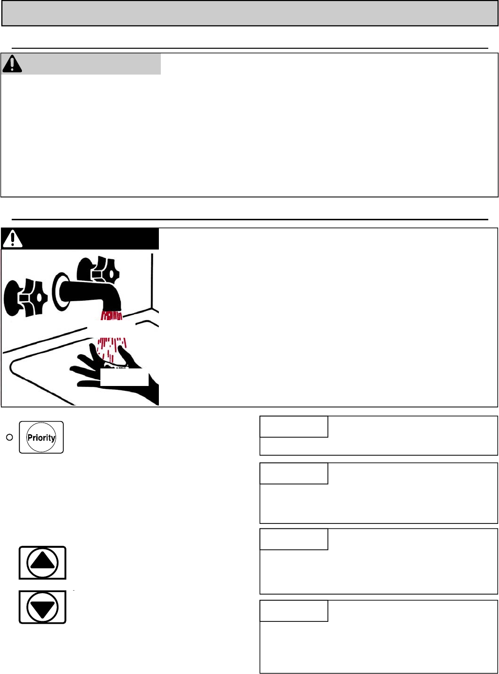
48 Manuel – Chauffe-eau d’intérieur série VB LS
Comportements et pratiques de sécurité
Réglage de température
Instructions d'utilisation
AVERTISSEMENT
• Gardez la zone autour de l’appareil dégagée et exempte
de matériaux combustibles, essence et autres vapeurs et
liquides inflammables.
• N’utilisez pas cet appareil s’il a été plongé dans l’eau,
même partiellement. Faites inspecter l’appareil par un
technicien qualifié et remplacez toute partie du système
de contrôle et toute commande qui ont été plongés dans
l’eau.
• Cet appareil est équipé d'une prise de trois-fourche pour
votre protection contre le risque de choc et devrait être
branché directement à un réceptacle correctement fondé
de trois-fourche. Ne coupez pas ou n'enlevez pas la
fourche moulue de cette prise.
• Toute altération de cet appareil ou de ses commandes
peut être dangereuse.
• Vérifiez toujours la température de l'eau avant d'entrer
sous la douche ou dans la baignoire.
1. Appuyez sur le bouton de priorité du
contrôleur à distance. Le voyant vert
de priorité va s'allumer pour montrer
que c'est ce contrôleur qui règle la
température de consigne et que le
chauffe-eau Rinnai est prêt à fournir
de l'eau chaude.
La température peut être ajustée entre
98º F (37 ºC) et 110º F (43 ºC) même en
cas de tirage d’eau.
AVIS
DANGER L'eau chaude peut être dangereuse, en particulier pour les enfants, les personnes
âgées et les infirmes. Il y a un risque d'échaudage si la consigne du thermostat est
réglée trop haut.
Des températures dépassant 125º F (52 ºC) peuvent causer de sévères brûlures ou
un échaudage, pouvant entraîner la mort.
L'eau chaude peut causer des brûlures au premier degré suite à des expositions
aussi limités que :
3 secondes à 140º F (60 ºC)
20 secondes à 130º F (54 ºC)
8 minutes à 120º F (49 ºC)
Testez la température de l'eau avant de placer un enfant sous la douche ou dans le
bain.
Ne laissez pas un enfant ou une personne infirme dans une baignoire sans
surveillance.
2. Appuyer sur les boutons ▲ou▼ pour
obtenir la valeur de température de
consigne voulue.
L’eau chaude est fournie à tous les
points de distribution à cette
température sauf un changement
désiré au point d’origine ou à
n’importe quelle commande.
Vérifiez vos normes locales concernant la
température maximale de l'eau permise
pour une utilisation dans maisons de
soins, écoles, garderies, et pour toutes
les autres applications publiques.
AVIS
Si une unité nouvellement installée avec
un contrôleur à distance n'a pas été
activée pendant au moins 6 heures, alors
sa température de consigne reviendra à
la valeur par défaut de 104º F (40 ºC) s'il
y a une interruption du secteur.
AVIS
Il peut y avoir une différence entre la
température de consigne affichée sur le
contrôleur à distance et la température
réelle au robinet, du fait des conditions
d'environnement, ou de la longueur de
tuyauterie depuis le chauffe-eau.
AVIS
Temp. d’eau
La préséance d'un contrôleur sur les
autres ne peut se modifier que s'il n'y
a pas d'eau chaude qui coule.
Chaud
Brûlure
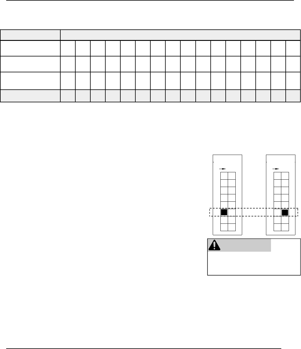
Manuel – Chauffe-eau d’intérieur série VB LS 49
Plages de température avec un contrôleur de température
Ce chauffe-eau va tenter de fournir de l'eau chaude à température stable malgré les variations de débit ou quand plus d'un
robinet est ouvert. La chauffe-eau ne peut délivrer de l'eau qu'à une seule température de consigne à la fois. Les températures
de consigne disponibles pour un modèle donné sont fournies ci-dessous :
Les températures suggérées sont de :
• Cuisine 120º F (49º C)
• Douche 98 - 110 ºF (37 - 43 ºC)
• Baignoire 102 - 110 ºF (39 - 43 ºC)
Ces températures ne sont que des suggestions.
Une température inférieure à 98º F (37 ºC) peut s'obtenir par
ajout d'eau froide avec un robinet mitigeur.
Pour passer l'affichage de température de Celsius à
Fahrenheit ou vice versa, actionnez et maintenez enfoncé le
bouton M/A pendant 5 secondes avec le chauffe-eau en
position d'arrêt.
Redéfinissant la température maximale (RL75 et RL94, uniquement)
* Modèles RL75 et RL94 ont une température maximale par défaut de 120º F (49º C)
et une option pour augmenter la température maximale de 140 ºF (60 ºC).
Les cadres de température de 125-140 ºF (52-60º C) sont disponible en réglant le
commutateur de baisse 6 à SUR dans le SW1 banque de 8 commutateurs de baisse.
** MCC-91 Contrôleur de Température Ces cadres exigent le MCC-91 contrôleur. Quand
le MCC-91 contrôleur est connecté, ces plus hautes températures sont disponibles sur
tous modèles de contrôleur dans le système. L'usage d'un MCC-91 contrôleur dans une
demeure résidentielle réduira la couverture de garantie à cela d'une application de garantie
commerciale.
Le MCC-91 contrôleur est l'intention eu pour les applications de publicité et hydronic
seulement. Si un MCC-91 contrôleur est utilisé dans une demeure résidentielle pour
une application de hydronics, une soupape mélangeant doit être aussi installée pour
limiter la température d'eau chaude potable à une température sûre. Arroser des
températures plus de 125º F (52º C) peut causer des brûlures ou scalding sévère.
Se référer à l'Alerte de Danger sur les températures d'eau. Rinnai ne fait pas, en tout
cas, être responsable des dommages qui résultent de tel usage impropre ou tel
mauvais usage.
Options de température sans contrôleur à distance
Le réglage de température de consigne par défaut pour cet appareil sans un contrôleur à distance est de 120º F (49 ºC). On
peut, si on le souhaite, la passer sur 140º F (60 ºC) en modifiant la position d'un seul micro-commutateur DIP.
À la banque SW1 de 8 interrupteurs à positions multiples, le micro-commutateur 5 donne un réglage à 120°F (49 ºC) s'il est
sur OFF (valeur automatique) mais à 140°F (60 ºC) s'il est sur ON.
Si un contrôleur de température est installé, alors le contact 5 n'a aucun effet sur des arrangements de température.
AVERTISSEMENT
NE touchez PAS aux autres micro-
commutateurs sauf s'il vous est
spécifiquement demandé de le faire.
Switch No.
F
O
F
8
5
7
6
4
3
ON
1
2
Switch No.
F
O
F
8
5
7
6
4
3
ON
1
2
Température Maximum
120º F (49º C) 140 ºF (60 ºC)
N°demicro‐
commutateur
N°demicro‐
commutateur
Un contrôleur plus ancien, MC-45, peut être installé avec le RL75i et le RL94i en déplaçant le commutateur no 6
dans la Banque de 6 commutateurs à ON. Certains paramètres de la température sera légèrement différente de
la table ci-dessus.
Model
RL75i 98 100 102 104 106 108 110 115 120 125
*
130
*
135
*
140
*
150
**
160
**
R98LSi
R98LSi-ASME 98 100 102 104 106 108 110 115 120 125 130 135 140 150
**
160
**
185
**
Temp in Celsius ºC 37 38 39 40 41 42 43 46 49 52 54 57 60 66 71 85
Plages de température disponible (ºF)
RL94i 98 100 102 104 106 108 110 115 120 125
*
130
*
135
*
140
*
150
**
160
**
185
**
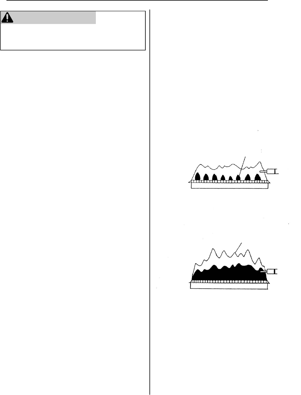
50 Manuel – Chauffe-eau d’intérieur série VB LS
AVERTISSEMENT
Coupez l'alimentation électrique, et fermez l'arrivée de gaz
et d'eau à leur vanne de coupure manuelle avant toute
intervention sur l'unité.
Les réparations ne doivent être effectuées que par un
technicien de service qualifié. Cet appareil doit être inspecté
annuellement par un technicien de service qualifié. Vérifiez
le bon fonctionnement après chaque intervention.
Nettoyage
Il est impératif de contrôler compartiments, brûleurs et
passages pour la circulation de l'air sur l'appareil à nettoyer.
Procédez au nettoyage comme ceci :
1. Coupez et débranchez l'alimentation électrique. Laissez
refroidir le chauffe-eau.
2. Fermez l'eau fermer les robinets. Démontez et nettoyez
le filtre d'arrivée d'eau.
3. Démontez le panneau frontal en enlevant ses 4 vis.
4. Utilisez de l'air comprimé pour dépoussiérer brûleur
principal, échangeur thermique et pales de ventilateur.
N'utilisez pas de chiffon mouillé ou de nettoyants à
pulvériser sur le brûleur. N'utilisez pas de substances
volatiles comme benzène ou diluants. Ils pourraient
s'enflammer ou décolorer la peinture.
5. Utilisez un chiffon doux sec pour essuyer le boîtier.
Système de ventilation
Les conduites de prise d'air et d'évacuation doivent être
inspectées au moins tous les ans pour y détecter des
blocages ou dommages éventuels.
Moteurs
Les moteurs sont lubrifiés à vie et ne demandent pas de
lubrification périodique. Maintenez ventilateur et moteur
sans poussière ou saleté en les nettoyant tous les ans.
Contrôleur à distance
Utilisez un chiffon humide pour nettoyer les contrôleurs à
distance. N'employez pas de solvants.
Accumulation de calcaire et de tartre
Si vous recevez le code d'erreur « LC », reportez-vous à la
procédure de rinçage de l'échangeur thermique. Voyez
aussi la section sur la qualité de l'eau pour savoir si votre
eau a besoin d'un traitement ou conditionnement en amont.
(Lors de la vérification de l'historique des anomalies pour
l'entretien, le code « 00 » aura remplacé « LC ».)
Inspection visuelle de flamme
Le brûleur doit être allumé de façon régulière sur toute sa
surface quand il fonctionne correctement. La flamme doit
être claire, bleutée et stable. Reportez-vous à la
décomposition par pièces du brûleur pour l'emplacement
des hublots d'inspection.
La configuration de flamme est illustrée ci-dessous :
Accumulation de neige
Maintenez la zone autour de la terminaison de cheminée
libre de toute neige et glace. Cet appareil ne peut pas bien
fonctionner si ses bouches d'aspiration et d'évacuation d'air
sont entravées (blocage total ou même partiel) par des
obstacles quelconques.
Entretien
CORRECT
VUE DE FACE
FLAMME
BLEUE
ÉLECTRODE DE
DÉTECTION
INCORRECT
VUE DE FACE
FLAMME JAUNE
ÉLECTRODE DE
DÉTECTION
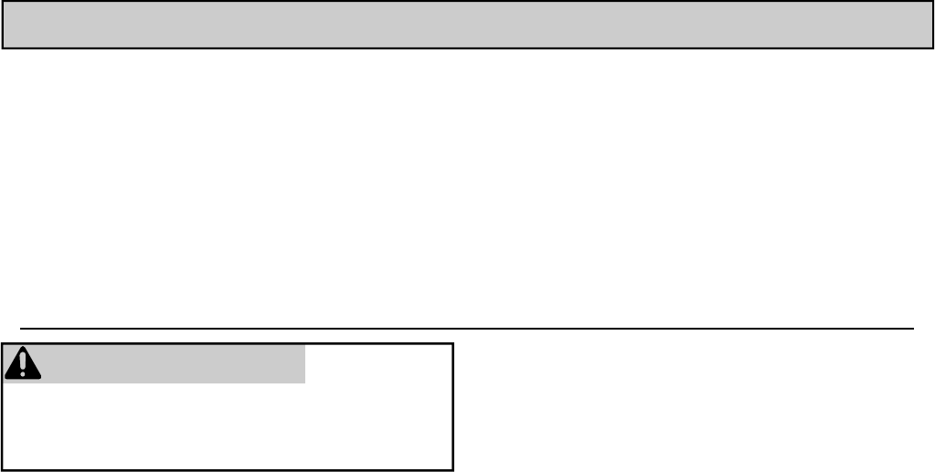
Manuel – Chauffe-eau d’intérieur série VB LS 51
Seuls des installateurs qualifiés avec une formation
adéquate peuvent installer cet appareil. La garantie
peut être annulée suite à une installation incorrecte
ou réalisée par un installateur non qualifié.
Rinnai recommande fortement que les installateurs
suivent une classe pour la connaissance des
produits. Pour vous informer sur les cours de
formation de Rinnai, appelez :
1-800-621-9419.
Installation Instructions
Instructions générales
• Cet appareil doit être installé par un sous-traitant qualifié
ou agréé. Il est de la responsabilité de la personne devant
faire installer un chauffe-eau de s'assurer que ce sous-
traitant installateur possède les autorisations et permis
adéquats pour installer des chauffe-eau dans votre
région. Rinnai recommande fortement que les
installateurs suivent une classe de connaissance de ses
appareils pour assurer la satisfaction du client et la
couverture par la garantie. Le non respect de
réglementations d'état ou de province relatifs à
l'installation de chauffe-eau peut annuler la garantie.
• Cet appareil n'est pas prévu pour une installation à
l'extérieur.
• C'est un installateur ou un technicien de service qualifié
qui doit installer, inspecter et vérifier l'absence de fuites
de cet appareil avant sa mise en service.
• L'installation doit être en conformité avec les normes
locales, et en leur absence avec la norme américaine sur
le gaz combustible, ANSI Z223.1/NFPA 54, ou la norme
canadienne sur les installations au gaz naturel et
propane, CSA B149.1.
• Cet appareil doit être installé selon la Manufactured Home
Construction and Safety Standard, Title 24 CFR, Part
3280 ou la norme CAN/CSA-Z240 MM M86, Maisons
mobiles.
• L'appareil, quand il est installé, doit être électriquement
relié à la terre en conformité avec la norme américaine
électrique, ANSI/NFPA 70, ou la norme canadienne
électrique, CSA C22.1.
• L'appareil et sa vanne de gaz doivent être débranchés de
la conduite d'alimentation en gaz durant les essais du
système en pression dépassant 1/2 psi (3.5 kPa ou 13,84
pouces de hauteur de colonne d'eau).
• L'appareil doit être isolé du système de conduite
d'alimentation en gaz en fermant sa vanne individuelle de
coupure durant les essais du système en pression
inférieurs ou égaux à 1/2 psi (3.5 kPa ou 13,84 pouces de
hauteur de colonne d'eau).
• Suivez les instructions d'installation et les conseils de
soins et entretien pour avoir de l'air de combustion et de
ventilation de façon adéquate.
• L'appareil doit être placé à un endroit où des fuites d'eau
venant de l'unité ou des raccordements n'entraîneront pas
de dommages dans les environs immédiats de l'appareil
ou aux étages inférieurs de la structure. Si un endroit
idéal n'est pas disponible, il est recommandé d'installer un
bac de récupération bien drainé sous l'appareil. Ce bac
ne doit pas freiner le flux de l'air de combustion.
• Le flux d'air de combustion et de ventilation ne doit pas
être obstrué.
• Cet appareil ne convient pas pour une utilisation dans une
application comme le chauffage d'eau de piscine ou de
spa utilisant de l'eau chimiquement traitée (cet appareil
peut par contre remplir de grandes baignoires ou bains à
tourbillon avec de l'eau potable chaude).
• Si un chauffe-eau est installé dans un système fermé
d'alimentation en eau, ayant par exemple un dispositif anti
-refoulement dans la conduite d'alimentation en eau
froide, il faut fournir les moyens de contrôler l'expansion
thermique. Contactez le fournisseur d'eau ou un
inspecteur en plomberie local sur la façon de gérer cette
situation.
• En cas de surchauffe, ou si la coupure du gaz ne se fait
pas, fermez l'arrivée de gaz au niveau de la vanne de
contrôle manuelle alimentant l'appareil.
• Gardez la zone d'aspiration d'air exempte de produits
chimiques comme chlore ou agent de blanchiment qui
produisent des fumées. Ces fumées pourraient
endommager des composants et réduire la durée de
service de votre appareil.
• Pour la conversion de type de gaz, contactez Rinnai.
AVERTISSEMENT
N'utilisez pas de matériaux de substitution.
N'utilisez sur cet appareil que des pièces certifiées
RL75i .................. REU-VB2528FFUD-US
RL94i .................. REU-VB2735FFUD-US
R98LSi ................ REU-VA3237FFU-US
R98LSi-ASME .... REU-VA3237FFU-ASME
La série VB (RL75i et RL94i) est certifiée pour l'installation à
domicile (mobile) fabriqués.
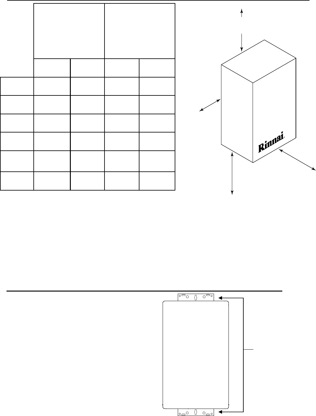
52 Manuel – Chauffe-eau d’intérieur série VB LS
Écartements par rapport à l'appareil
1. Identifiez l'emplacement d'installation et confirmez que
là les espacements requis seront respectés.
2. Fixez bien le chauffe-eau au mur en utilisant n'importe
lesquels des trous des supports d'installation murale
placés en haut et en bas du chauffe-eau. Assurez-vous
que la résistance des fixations est suffisante pour
supporter le poids de l'appareil. Reportez-vous au
poids des modèles de chauffe-eau dans la section des
spécifications.
Fixation du chauffe-eau
Supports
d'installation
murale
Jusqu'à matières
combustibles
Jusqu'à
matières
non-combustibles
RL75i
RL94i R98LSi RL75i
RL94i R98LSi
Dessus du
chauffe-eau 6 pouces **
(152 mm)
12 pouces
(305 mm)
2 pouces**
(51 mm)
2 pouces
(51 mm)
Arrière du
chauffe-eau 0 (zero) 0 (zero) 0 (zero) 0 (zero)
Avant du
chauffe-eau 6 pouces
(152 mm)
6 pouces
(152 mm)
6 pouces
(152 mm)
6 pouces
(152 mm)
Côtés du
chauffe-eau 2 pouces
(51 mm)
2 pouces
(51 mm)
1/2 pouce
(13 mm)
1/2 pouce
(13 mm)
Par rapport
au plancher/
sol
12 pouces
(305 mm)
12 pouces
(305 mm)
12 pouces
(305 mm)
2 pouces
(51 mm)
Ventilation 0 (zero) 4 pouces* 0 (zero) 0 (zero)
* 4 pouces (102 mm) pour zone confinée ; 1 pouce (26 mm) pour zone ouverte.
L'espacement pour des interventions doit faire 24 pouces (610 mm) sur l'avant du chauffe-eau.
Pour installation en placard : espacement de 6 pouces (152 mm) à l'avant.
** 0 pouces des composants de ventilation et de la canalisation de vidange condensat.
to side
to front
to top
to floor/ground
Vers le haut
Sur le côté
Vers le sol
Vers l'avant
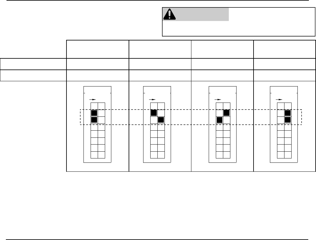
Manuel – Chauffe-eau d’intérieur série VB LS 53
Installation à altitude élevée
Micro-commutateur 0-2000 ft
(0-610 m)
2001-5200 ft
(610-1585 m)
5201-7700 ft
(1585-2347 m)
7701-10200 ft
(2347-3109 m)
N° 2 OFF OFF ON ON
N° 3 OFF ON OFF ON
Switch No.
F
O
F
8
5
7
6
4
3
ON
1
2
Switch No.
F
O
F
8
5
7
6
4
3
ON
1
2
Switch No.
F
O
F
8
5
7
6
4
3
ON
1
2
Switch No.
F
O
F
8
5
7
6
4
3
ON
1
2
Disposez les micro-commutateurs N° 2 et N° 3 sur les
positions montrées dans le tableau qui suit en fonction
de votre altitude d'installation.
AVERTISSEMENT NE modifiez PAS la disposition
des autres micro-commutateurs
sauf sur instructions
spécifiques.
N°demicro‐
commutateur
N°demicro‐
commutateur
N°demicro‐
commutateur
N°demicro‐
commutateur
• Une vanne manuelle de coupure de gaz doit être placée
sur la conduite d'alimentation en gaz en amont du chauffe
-eau Rinnai. Un raccord union peut être utilisé sur la
connexion au-dessus de la vanne de coupure pour
pouvoir ultérieurement intervenir sur l'unité en la
déconnectant.
• Vérifiez le type de gaz d'arrivée et sa pression avant de
raccorder le chauffe-eau Rinnai. Si l'appareil a besoin
d'un gaz qui n'est pas celui disponible localement, NE
branchez PAS le chauffe-eau Rinnai. Contactez votre
revendeur pour obtenir le bon modèle correspondant à
votre type de gaz.
• Vérifiez la pression du gaz d'alimentation immédiatement
en amont à l'arrivée de la régie fournissant le gaz. La
pression d'arrivée du gaz doit être dans la fourchette de
limites montrée dans la section de spécifications.
• Avant de mettre l'appareil en service, tous les joints, y
compris sur le chauffe-eau, doivent avoir leur étanchéité
vérifiée, au moyen d'une solution de détection de fuites à
l'eau savonneuse, ou une solution ininflammable
équivalente éventuellement (comme certaines solutions
pour détection de fuites de gaz, incluant l'eau
savonneuse, peuvent causer corrosion ou fissuration par
contrainte, la tuyauterie doit être rincée avec de l'eau
après le test, sauf si vous avez pu déterminer que la
solution de détection utilisée n'était pas corrosive).
• Utilisez toujours des connecteurs approuvés pour
raccorder l'unité sur la conduite de gaz. Purgez toujours la
conduite de gaz de tous débris éventuels avant son
branchement sur le chauffe-eau;
• La conduite d'alimentation en gaz doit être étanche au
gaz, du bon calibre et installée d'une façon permettant de
fournir assez de gaz pour satisfaire la demande maximale
du chauffe-eau et de tous les autres appareils
fonctionnant au gaz du lieu sans qu'il y ait de chute de
pression.
• Tout composé utilisé sur la jonction filetée du tuyau de
gaz doit être d'un type qui résiste à l'action du gaz
propane ou naturel.
• Reportez-vous à un tableau de calibrage approuvé de
tuyauterie de gaz si vous avez un doute sur la taille de
votre conduite.
Instructions générales
Tuyauterie de gaz
Pour les installations canadiennes, reportez-vous à la page 36.
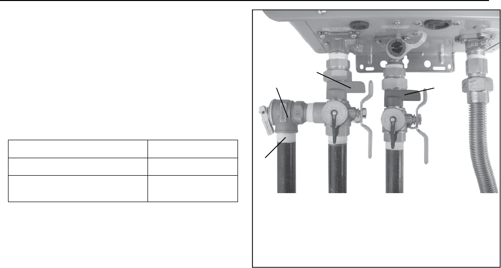
54 Manuel – Chauffe-eau d’intérieur série VB LS
Tuyauterie d'eau
Valve à Bille / Valve de dégagement de
pression (RL75i, RL94i)
Les soupapes d'isolement offrent la possibilité d'isoler le
chauffe-eau de la structure plomberie et de permettre un
accès rapide à vider l'échangeur de chaleur. Vérifiez auprès
des codes locaux pour déterminer si une soupape de
pression et de température est nécessaire. Les valves
inclus rencontrer American National Standard (ANSI
Z21.10.3)-norme canadienne (ASC 4.3) et sont ANSI/NSF
65 approuvé pour l'eau potable.
Instructions d’Installation:
1. Enveloppez les bouts filetés des prises d’eau et sorties
d’eau du chauffe-eau sans réservoir, ainsi que le bout
fileté de la valve de détente approuvée avec un
minimum de 5 enrobages de bande Teflon®.
2. Vissez la valve de dégagement de pression dans les
bouts filetés ¾’’ à l’opposé du levier pour clapet de
retenue sur la valve de service à eau CHAUDE. (Levier
de drainage ROUGE).
3. Désserrez l’écrou union de ¾’’ sur la valve à eau
CHAUDE et raccordez le à la sortie d’eau CHAUDE sur
le chauffe-eau sans réservoir. Si l’écrou est enlevé,
assurez-vous de réaligner l’about correctement avec la
valve et que la rondelle noire soit positionnée de façon à
ce que le l’arête de métal de la valve soit à l’intérieur de
la rondelle.
4. Alignez la direction du purgeur d’eau CHAUDE à la
position désirée.
5. Resserrez l’assemblage union de la valve à eau
CHAUDE en utilisant approximativement 15 pied- livres
de torsion.
6. Répétez les étapes 3-5 pour la valve à eau FROIDE.
(Levier de drainage BLEU) pour la connexion de la prise
d’eau FROIDE sur le chauffe-eau sans réservoir.
7. Raccordez l’ENTRÉE de la valve à eau FROIDE à la
source d’alimentation en eau PRINCIPALE.
8. Raccordez la SORTIE de la valve à eau CHAUDE à
l’EAU CHAUDE du système de plomberie.
9. Assurez-vous que les deux leviers de drainage soient
en position fermée, (perpendiculaires à la portion
drainage du corps).
Valve à Bille Eau Chaude 107000081
Valve à Bille Eau Froide 107000083
Valve de dégagement de
pression (VDP) 107000085
Valve de dégagement de pression Instructions
d’Installation:
La VDP doit être raccordée par la connexion filetée opposée
à la valve pour clapet de retenue sur la valve d’eau chaude
(désignée par le levier de drainage ROUGE) ou par la
connexion filetée du côté de l’accessoire de relocalisation au
dessus de la valve à eau chaude. L’installation doit maintenir
un diamètre de passage de ¾’’ sans aucune valve de
sectionnement ou restriction de ligne entre l’appareil et la
VDP. La conduite de refoulement depuis la VDP devrait être
en pente descendante et se terminer à 6’’ au dessus des
drains où le refoulement sera visible. Le bout de refoulement
de la ligne devrait être non-fileté et avoir un diamètre
minimum de ¾’’. La matériel de la ligne de refoulement doit
être adapté pour une température d’eau de 180° Fahrenheit
et ne doit pas dépasser 30 pieds de longueur ni contenir
plus de 4 coudes ou flexions transversales. Aucune valve
d’aucune sorte ne doit être installée dans la ligne de
refoulement de la valve de dégagement de pression.
Instructions d’Entretien pour la VDP :
Pour un entretien adéquat de cette valve de dégagement de
pression, nous recommandons l’opération de la valve en
position manuelle, une fois l’an. En ce faisant, il sera
nécessaire de prendre toutes les précautions quant à
l’écoulement potentiel d’eau bouillante sous pression.
Assurez-vous que l’écoulement soit dirigé dans un endroit
prédéterminé. Tout contact avec le corps ou autres objets
peut causer des dommages ou des blessures.
Prière de noter que le VDP inclus dans cet emballage est
certifié par CSA International en tant qu’item approuvé.
A Valve de dégagement de pression (VDP)
B Orifice de Refoulement pour VDP
C Levier de Drainage pour Valve à Bille Eau Chaude
D Levier de Drainage pour Valve à Bille Eau Froide
A
B
C
D
Manuel – Chauffe-eau d’intérieur série VB LS 55
• Une vanne manuelle de coupure d'eau doit intercalée sur
la conduite en amont sur l'arrivée d'eau au chauffe-eau
Rinnai. Des raccords union peuvent s'utiliser sur les
conduites d'eau froide et d'eau chaude pour faciliter les
interventions ultérieures avec déconnexion de l'unité.
• La tuyauterie (incluant les matériaux de soudage) et les
composants connectés à cet appareil doivent être approuvés
pour une utilisation sur des systèmes à eau potable.
• Purgez la conduite d'eau pour en éliminer les débris et
l'air. Des débris entrant dans le chauffe-eau Rinnai
pourraient l'endommager.
• Des produits chimiques toxiques, comme ceux utilisés
pour le traitement d'eau de chaudière, ne doivent pas être
utilisés dans l'eau potable utilisée pour le chauffage des
locaux.
• Si l'appareil doit être utilisé comme source d'eau potable,
il ne doit pas être connecté à un appareil utilisé
auparavant comme chauffage et fourniture d’eau non
potable.
• Le filtre d’eau du chauffage Rinnai dout être propre et
installé.
Instructions générales
Soupape de sûreté
• Une soupape de sûreté est nécessaire, d'un type
approuvé par les normes américaines (ANSI Z21.10.3) et
canadiennes (CSA 4.3) pour tous les systèmes de
chauffage par eau.
• La soupape de sûreté doit être compatible avec les
normes ANSI Z21.22 (soupapes de sûreté et dispositifs
de coupure automatique de gaz pour systèmes de
fourniture d'eau chaude) et/ou CAN1-4.4 (soupapes de
sûreté combinées à pression et à température et
soupapes casse-vide).
• La soupape de sûreté doit être homologuée pour 150 PSI
(1034 kPa) et au moins la valeur maximum de BTU/H de
l'appareil.
• Le déversement venant de la soupape de sûreté doit être
amené par tuyau au sol ou dans un système de drainage
pour éviter une exposition avec possibilité de brûlure pour
humains, végétaux ou animaux. Conformez-vous aux
normes locales. L'eau chaude sortant de la soupape de
sûreté peut causer des brûlures sévères et des
échaudages pouvant même provoquer la mort.
• La soupape de sûreté doit être actionnée manuellement
au moins une fois par an pour vérifier qu'elle est toujours
fonctionnelle.
• La soupape de sûreté doit être insérée dans la conduite
de sortie d'eau chaude en suivant les instructions du
fabricant. N'intercalez PAS n'importe quel autre type de
vanne ou dispositif de coupure entre la soupape de sûreté
et le chauffe-eau.
• Ne bouchez pas la soupape de sûreté, et n'installez
aucun raccord réducteur ou autre restriction dans la
conduite de déversement. Elle doit permettre un drainage
complet de la soupape et de la conduite.
• Si une soupape de sûreté déverse périodiquement, cela
peut venir d'une expansion thermique dans un système
d'eau fermé. Contactez votre fournisseur d'eau ou votre
inspecteur de plomberie local pour voir comment régler
cette situation. Mais ne bouchez pas la soupape.
• Ni Rinnai ni la norme nationale américaine (ANSI
Z21.10.3) ou canadienne (CSA 4.3) n'exigent d'utiliser
une soupape de sûreté combinée à pression et à
température pour cet appareil. Cependant des normes
locales peuvent le demander.
Parmi les soins à apporter à votre chauffe-eau il y a
l'évaluation de la qualité de l'eau consommée. Si les
paramètres de votre eau dépassent les limites fournies dans
ce tableau, il vous faudra traiter ou conditionner cette eau.
* Source : Part 143 National Secondary Drinking Water
Regulations (normes américaines sur les réseaux
d'alimentation secondaires en eau potable)
Niveau maximum
Dureté totale Jusqu'à 200 mg/L
Aluminium* Jusqu'à 0,2 mg/L
Chlorures* Jusqu'à 250 mg/L
Cuivre* Jusqu'à 1,0 mg/L
Fer* Jusqu'à 0,3 mg/L
Manganèse* Jusqu'à 0,05 mg/L
pH * 6,5 à 8,5
Matières dissoutes
totales (MDT)*
Jusqu'à 500 mg/L
Zinc * Jusqu'à 5 mg/L
Qualité de l'eau
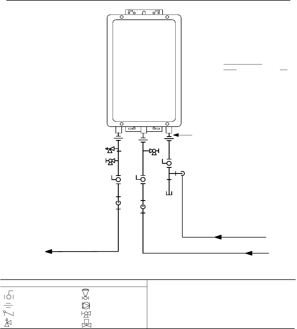
56 Manuel – Chauffe-eau d’intérieur série VB LS
Tuyauterie recommandée pour installation de base
GasSupply
3/4"ColdWaterSupplyLine
3/4" Hot Water Supply Line
Rinnai
Water Heater
Rinnai
Equipment List
Rinnai
Water Heaters
RIK-KIT (Optional)
(3/4" Fittings Include:
2 Unions, 2 Ball Valves,
2Drain Valves and
1 Pressure Relief Valve.)
QTY
1
1
3/4"GasConnection
For Building Fixtures
This is not an engineered drawing, it is intended only as a guide and
not as a replacement for professionally engineered project drawings.
This drawing is not intended to describe a complete system, it is up
to the contractor/engineer to determine the necessary components
for and configuration of the particular system being installed. The
drawing does not imply compliance with local building code
requirements. It is the engineer/contractor responsiblity to ensure
the installation is in accordance with all local building codes. Confer
with local building officials before installation.
Pressure Relief Valve
3/4" Ball Valve
3/4" Union
Check Valve
S
Pressure Regulator
Circulating Pump
Solenoid Valve
Boiler Drain Valve
KEY
Chauffe-eau
Rinnai
Liste d'équipement
Rinnai Qté
Chauffe-eau Rinnai 1
Kit RIK (optionnel) 1
(raccords 3/4 po (19 mm)
comprenant :
2 unions, 2 vannes à boisseau
sphérique, 2 électrovannes de
drainage, 1 soupape de sûreté)
Connexion de gaz en 3/4 po
(19 mm)
Alimentation en gaz
Conduite d'alimentation en eau froide en 3/4 po (19 mm)
Conduite de sortie d'eau chaude en 3/4 po
(19 mm)
Appareils du bâtiment
Vanne à tournant sphérique
3/4 po (19 mm)
Raccord union 3/4 po (19 mm)
Clapet anti-retour
Soupape de décharge
Régulateur de pression
Pompe de circulation
Vanne de purge de
chaudière
Électrovanne
Légende Ceci n'est pas un schéma technique, son but n'est que de vous guider, et il ne tient
pas lieu de dessin industriel professionnel pour un projet. Ce schéma n'a pas
l'ambition de décrire un système au complet. C'est la responsabilité du concepteur
ou de l'ingénieur de déterminer les composants nécessaires et la configuration
pour le système spécifique à installer. Ce schéma n'implique aucune conformité
avec les exigences des normes de construction locales. C'est la responsabilité du
concepteur ou de l'ingénieur de s'assurer que l'installation sera en conformité avec
toutes les normes locales de construction applicables. Consultez les autorités
compétentes dans ce domaine avant l'installation.
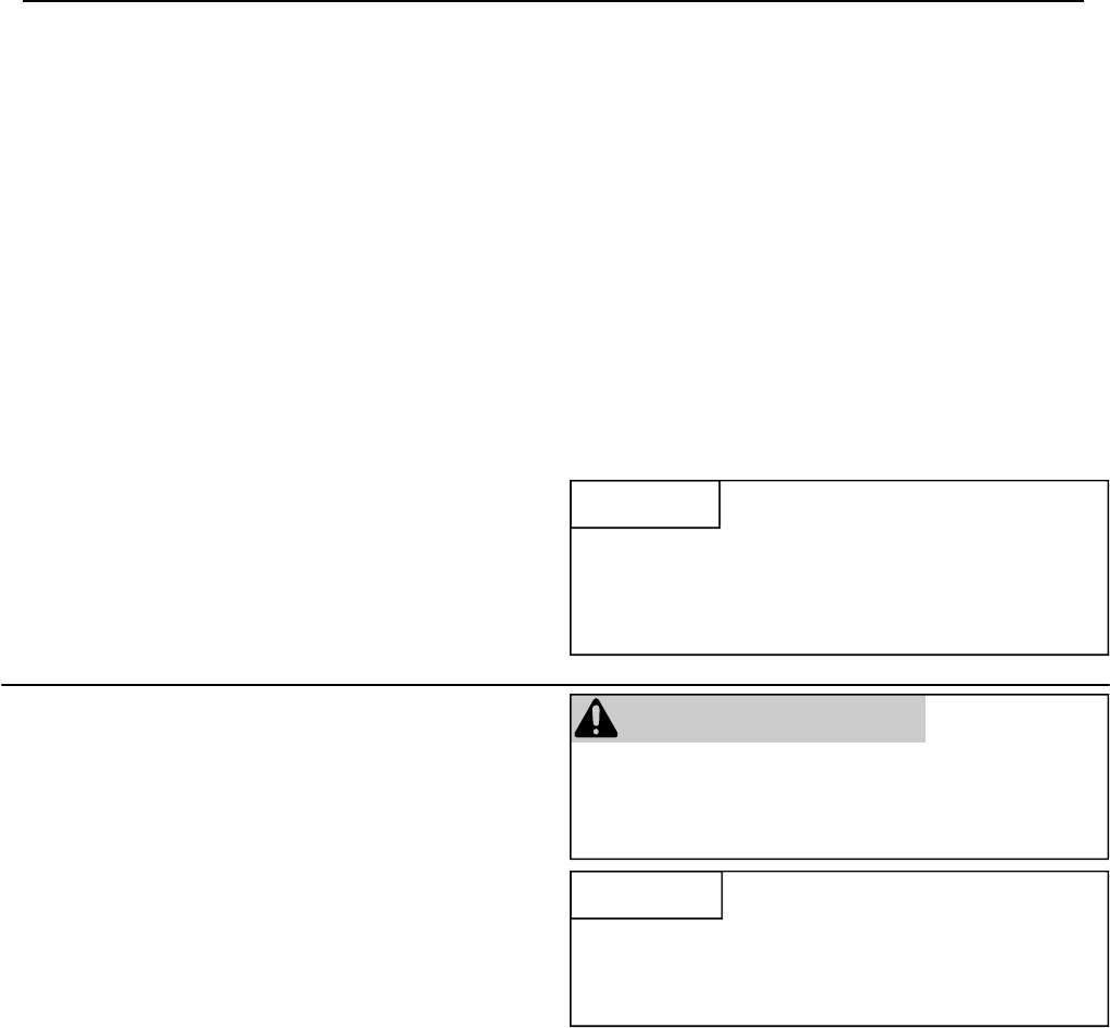
Manuel – Chauffe-eau d’intérieur série VB LS 57
Instructions de ventilation
• Les terminaisons verticales doivent incorporer un drainage
de condensat et un piège aussi près que possible de
l'appareil.
• Le chauffage de l'eau RL75i et RL94i a un collecteur de
condensat intégré.
• Rinnai offre un piège de condensats.
• Dans les régions à climat froid il se produira plus de
condensat dans le système de ventilation. Un collecteur de
condensat est recommandé pour ces climats.
• Utiliser uniquement le vent qui est approuvé et identifié
comme acceptable pour votre modèle particulier.
• N'utilisez pas de vent cette appliance en PVC, CPVC, ABS
ou matériau galvanisé.
• Pente la ventilation vers l'appliance selon les instructions
d'installation du fabricant évent.
• Rejetez le condensat en respectant les normes locales.
• Utiliser uniquement des tuyaux en PVC ou CPVC pour la
ligne de cerveaux de condensats.
• Le tuyau de cerveaux condensat doit être aussi courte que
possible et ont une hauteur de ton vers le bas.
• Ne branchez pas le tuyau de cerveaux condensat
directement à l'égout de pluie.
• Le tuyau de cerveaux condensat (sur toute sa longueur)
doit être au moins le même diamètre que la ligne de
cerveaux.
• La fin de la conduite de cerveaux condensat doit être
ouverte à l'atmosphère. La fin ne devrait pas être sous
l'eau ou d'autres substances.
• Ne branchez pas la ligne de cerveaux condensat avec une
climatisation Evaporateur bobine des cerveaux.
• Pour minimiser la congélation du condensat, exécutez la
ligne de cerveaux de condensat à travers un mur intérieur
ou entre l'isolation et un mur intérieur.
• Le collecteur de condensat devrait être utilisé pour toutes
les applications de chauffage hydronic.
Condensat
La formation de condensat peut arriver même sur les
appareils à ventilation directe de haute performance. Pour
éviter que le condensat n'endommage, suivez ces
instructions :
AVIS
Des dispositions doivent être prises pour éviter que du
condensat n'entre dans le chauffe-eau. Sans un drainage
adéquat et un rejet, le condensat peut endommager
l'échangeur thermique.
• Ce chauffe-eau est un modèle à ventilation directe, et de
ce fait est certifié et listé avec son système de ventilation.
Vous devez utiliser des composants de ventilation qui sont
certifiés et listés avec le modèle de chauffe-eau. Ne
combinez pas de composants de ventilation venant de
constructeurs différents.
• Le système de ventilation doit vent directement à
l'extérieur du bâtiment et d'utiliser l'air extérieur à la
combustion.
• Le système doit ventiler directement vers l'extérieur du
bâtiment et utiliser de l'air extérieur pour la combustion.
• La ventilation doit être aussi directe que possible avec un
minimum de raccords de tuyauterie.
• Évitez les abaissements et fléchissements sur les tronçons
de ventilation horizontaux en installant des supports en
suivant les installations du fabricant de la ventilation.
• Supportez les tronçons de ventilation horizontaux tous les
4' (1,2 m) et les tronçons verticaux tous les 6' (1,8 m), ou
en conformité avec les normes locales.
• Le diamètre de ventilation ne doit pas comporter de
réductions.
• Ne connectez pas le système de ventilation sur une
ventilation ou une cheminée existante.
• Ne partagez pas la ventilation avec le tuyau de ventilation
de tout autre chauffe-eau ou appareillage.
• Les connexions de ventilation doivent être fermement
pressées ensemble de façon à ce que leurs jonctions
forment une bonne étanchéité à l'air.
• La pièce de ventilation connectée sur le chauffe-eau doit
être fixée avec une vis autotaraudeuse.
• Reportez-vous aux instructions du constructeur de la
ventilation pour les instructions d'assemblage des
différents éléments.
• Si le circuit de mise à l'air libre doit être enfermé, on le
suggère que la conception de la clôture permette
l'inspection du circuit de mise à l'air libre. La conception
d'une telle clôture sera considérée acceptable par
l'installateur ou l'inspecteur local.
Consignes pour aspiration/évacuation Référez-vous aux instructions spécifiques sur votre produit de
ventilation pour les exigences supplémentaires d'installation.
AVIS
S'il devient nécessaire d'accéder à un circuit de mise à l'air
libre inclus pour le service ou les réparations, Rinnai n'est
pas responsable d'aucuns coûts ou difficulté en accédant au
circuit de mise à l'air libre. La garantie ne couvre pas obtenir
l'accès à un circuit de mise à l'air libre inclus.
AVERTISSEMENT
Si un collecteur de condensat n'est pas utilisé, le tuyau
de drainage doit être capuchonnée pour éviter que gaz
d'échappement et condensat n'entrent dans le bâtiment.
Ce capuchon est livré sur l'appareil.
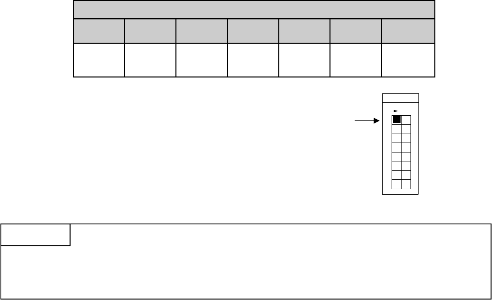
58 Manuel – Chauffe-eau d’intérieur série VB LS
Nombre de coudes à 90°
0 1 2 3 4 5 6
41 ft 1
(12.5 m)
35 ft 2
(10.7 m)
29 ft 3
(8.8 m)
23 ft 4
(7.0 m)
17 ft 4
(5.2 m)
11 ft 4
(3.4 m)
5 ft 4
(1.5 m)
Notes 1234
Switch No.
F
O
F
8
5
7
6
4
3
ON
1
2
Exemple : Si vous n'avez qu'un coude votre longueur de ventilation maximum est alors de 35 pieds (10,7 m). Si votre
longueur effective fait plus de 15 pieds (4,6 m) vous devez passer le microcommutateur N° 1 (SW1) en position
OFF.
Longueur maximum de ventilation
1. Déterminez le nombre de coudes à 90° dans le système de ventilation (deux coudes à 45° comptent pour un coude à 90°.
Sur les modèles R98 chaque pied de conduite semi flexible utilisée dans la longueur d'inspiration d'air équivaut à un
coude à 90°).
2. Référez-vous au tableau pour trouver la longueur de ventilation maximum sur la base du nombre de coudes.
3. Suivez les recommandations de la note applicable.
1 Si la longueur fait plus de 21' (6,4 m) passez le
microcommutateur N° 1 (SW1) en position OFF.
2 Si la longueur fait plus de 15' (4,6 m) passez le
microcommutateur N° 1 (SW1) en position OFF.
3 Si la longueur fait plus de 9' (2,7 m) passez le
microcommutateur N° 1 (SW1) en position OFF.
4 Passez le microcommutateur N° 1 (SW1) en position
OFF.
Si vous avez une longueur de ventilation plus grande, le microcommutateur N° 1 doit être mis en position OFF. Cela
assure que le chauffe-eau fonctionne correctement. Des codes d'erreur de conduit de cheminée obstruée et des coupures
peuvent arriver si ce microcommutateur N° 1 n'est pas en position correcte. Sur le RL94i, la capacité maximale de débit
d'eau sera réduite d'environ 10% quand ce microcommutateur N° 1 est en position OFF.
AVIS
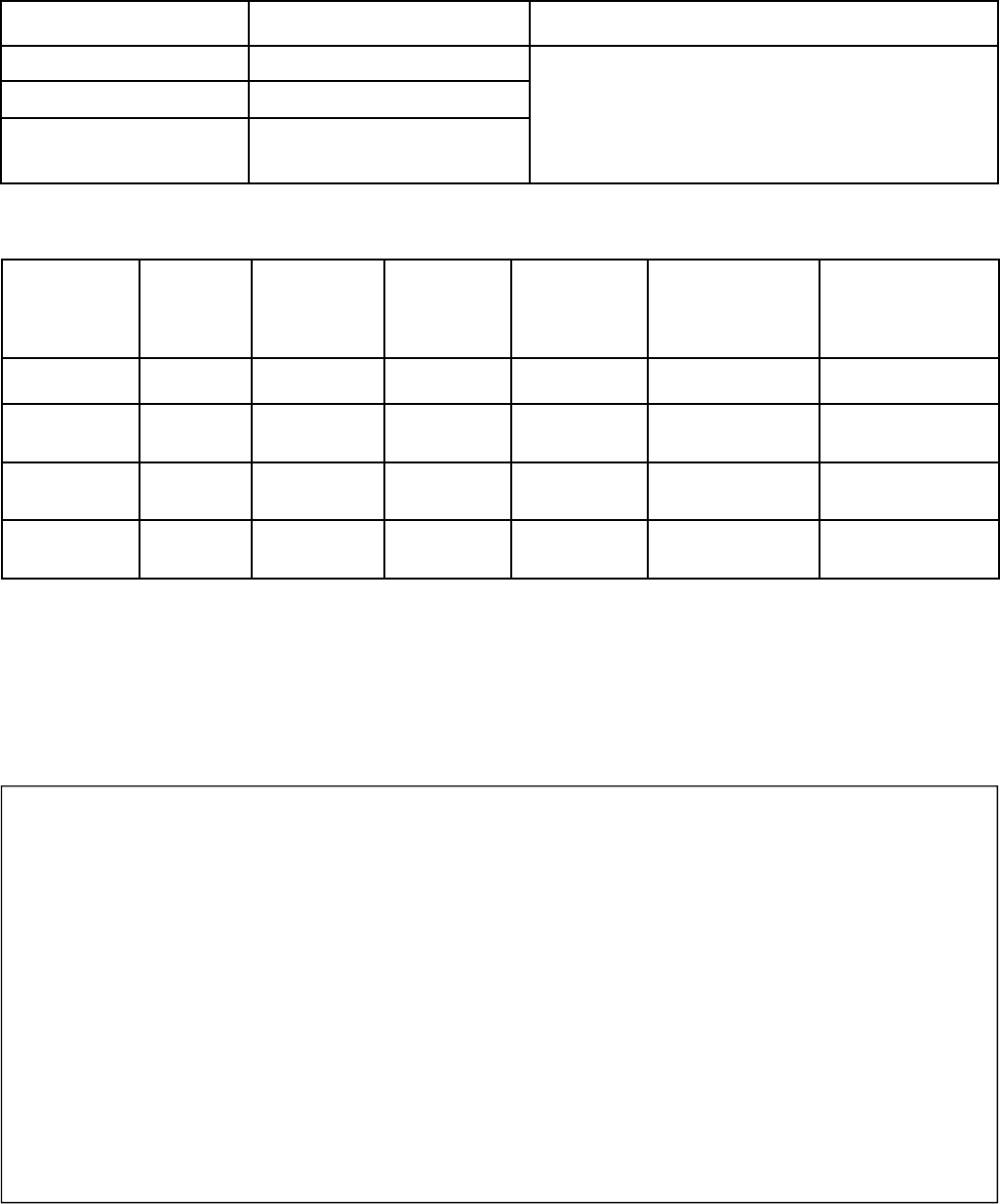
Manuel – Chauffe-eau d’intérieur série VB LS 59
Manufacturer Product Adaptateur
d'appareil
Terminaison
Vertical
Terminaison
horizontale
Terminaison
horizontale
concentrique
Heat-Fab Saf-T Vent 9401AMTK 5400CI 9492 NA
Z-Flex Z-Vent 2SVSNA04.5 2SVSRCF4 2SVSTPX4 NA
ProTech
Systems FasNSeal FSAAU4 * FSRC4 * FSBS4 * FSDVPTB04LH *
FSDVWT4
Metal-Fab Corr/Guard 4CGOA 4CGSWC 4CGSWMCM 4CG7HT90
4CG7HT
Terminaison
horizontale
concentrique
réglable
NA
NA
FSDVWMTP4LH,
FSEDVWMTP4LH
NA
FSAAU4 - demandez le FSAAU4SP (monobloc)
FSRC4 - demandez le kit FSVPK4 de solin de toit à pas
variable (inclut chapeau contre la pluie FSRC4, mitre,
support de fixation rigide et solin de toit)
FSBS4 - demandez le FSBS4SP (monobloc)
FSDVPTB04LH - demandez le kit FSDV WMT04LH (inclut
traversée pour ventilation directe FSDVPTB04LH, grillage
aviaire, plaques de montage intérieures et extérieures,
adaptateur d'appareil, conduite en aluminium flexible de
3 pieds avec 2 colliers, et longueur verticale ajustable)
* En commandant chez Rinnai, demandez ces numéros de pièces et de kits :
Contacts avec les constructeurs de ventilation pour des informations d'installation et de liste de pièces :
Produits de ventilation
Constructeur Produit Pièces
Rinnai/Ubbink Système de ventilation Rolux
Heat-Fab Système de ventilation SC Saf-T
Metal-Fab Système de ventilation/admission
d'air Com/Guard
Reportez-vous aux documents techniques du constructeur
pour les numéros de pièces spécifiques et les instructions.
Produits de ventilation listés et testés
pour RL75i ....................... REU-VB2528FFUD-US
RL94i ....................... REU-VB2735FFUD-US
Produits de ventilation listés et testés
pour R98LSi ..................... REU-VA3237FFU
R98LSi-ASME ......... REU-VA3237FFU-ASME
Heat-Fab
Téléphone : 800-772-0739
Fax : 413-863-4803
Courriel : custsvc@heat-fab.com
Site Web : www.heatfab.com
Rinnai/Ubbink
Téléphone : 800-621-9419
Fax : 678-829-1666
Site Web : www.rinnai.us
Metal-Fab Inc.
Téléphone : 800-835-2830
316-943-2351
Fax : 316-943-2717
Courriel : info@mtlfab.com
Site Web : www.metal-fabinc.com
ProTech Systems, Inc.
Téléphone : 800-766-3473
518-463-7284
Fax : 518-463-5271
Courriel : support@protechinfo.com
Site Web : www.protechinfo.com
Z-Flex
Téléphone : 800-654-5600
Fax : 888-889-3539
Courriel : sales@z-flex.com
Site Web : www.novaflex.com
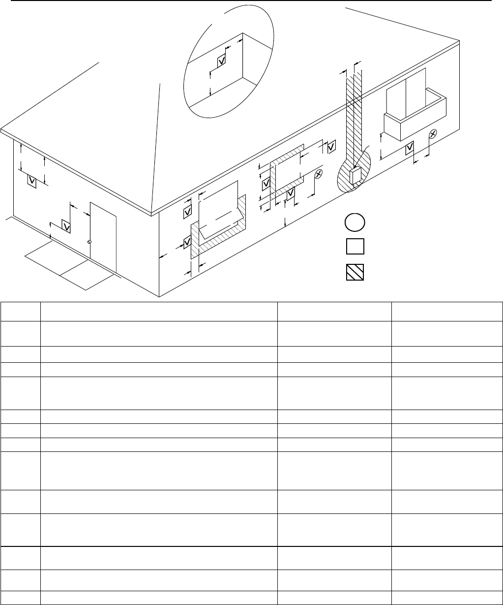
60 Manuel – Chauffe-eau d’intérieur série VB LS
INSIDE
CORNER DETAI L
FIXED
CLOSED
OPERABLE
FIXED
CLOSED
OPERABLE
B
B
B
A
J
BM
C
F
B
B
E
D
L
G
A
H
K
I
Réf. Description Installations au Canada Installations aux USA
A Espace au dessus de niveau du sol, véranda, porche, plate-forme
ou balcon 12" (30 cm) 12" (30 cm)
B Écartement par rapport à fenêtre ou porte qui peut s'ouvrir 36" (91 cm) 12" (30 cm)
C Écartement par rapport à fenêtre toujours fermée * *
D
Espacement vertical par rapport à combles ventilés, situés
au-dessus de la terminaison à une distance horizontale de
2 ' (61 cm) de la ligne centrale de terminaison
* *
E Espacement vertical par rapport à combles non ventilés * *
F Écartement par rapport à un angle extérieur * *
G Écartement par rapport à un angle intérieur * *
H Espacement par rapport à chaque côté d'une ligne centrale
prolongée au-dessus de l'ensemble de compteur/régulateur
3 pieds (91 cm) avec une
hauteur de 15 pieds (4,5 m)
au-dessus de l'ensemble
de régulation
*
I Écartement par rapport à la sortie de ventilation du régulateur
de service 36 " (91 cm) *
J
Écartement par rapport à entrée d'alimentation d'air non
mécanique dans le bâtiment ou entrée d'air de combustion
vers tout autre appareil
36 " (91 cm) 12" (30 cm)
K Écartement par rapport à entrée d'alimentation d'air mécanique 6' (1,83 m) 3' (91 cm) au dessus si à
10' (3 m) horizontalement
L Espacement au dessus d' un trottoir ou passage pavé situé dans
le domaine public 7' (2,13 m) 1 *
M Espacement sous véranda, porche, plate-forme ou balcon 12" (30 cm) 2 *
1 Une ventilation ne doit pas se terminer directement au-dessus d'un trottoir ou passage pavé situé entre deux habitations familiales et les desservant toutes
les deux.
2 Permis uniquement si véranda, porche, plate-forme ou balcon est entièrement ouvert au moins sur deux côtés en dessous du plancher.
* Pour les espacements non spécifiés dans ANSI Z223.1/NFPA 54 ou CSA B149.1, il faut appliquer les valeurs conformes aux normes locales d'installation et
aux exigences du fournisseur de gaz..
L'espacement par rapport au mur opposé est de 24" (60 cm) pour Canada et USA.
X
V
ENTÉE D'ALIMENTATION
EN AIR
TERMINAISON DE
VENTILATION
ZONE OÙ LA TERMINAISON
N'EST PAS PERMISE
FERMETURE
PERMANENTE
OUVRABLE
DÉTAIL D'ANGLE
INTÉRIEUR
OUVRABLE
FERMETURE
PERMANENTE
Espacements pour terminaison de cheminée (ANS Z21.10.3, CSA 4.3)
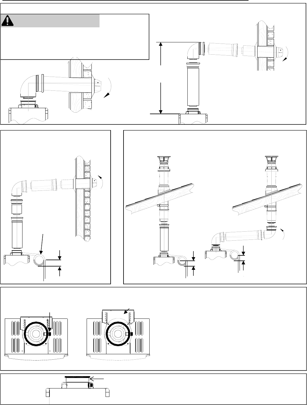
Manuel – Chauffe-eau d’intérieur série VB LS 61
Installation de conduit de cheminée (RL75i, RL94i)
3 in (75 mm)
minimum
Condensate
Trap
Terminaison verticale
(collecteur de condensat requis pour toutes les
installations)
3 in (75 mm)
minimum
3 in (75 mm)
minimum
Terminaison horizontale
avec collecteur de condensat
3 in (75 mm)
minimum
Piège à
condensat
Pour régler la position du collecteur de condensat, ou
remplacer le haut de ventilation femelle par un male :
1. Desserrez les 4 vis du support arrière.
2. Faites glisser le support du haut de ventilation femelle.
3. Enlevez les 4 vis fixant le haut de ventilation femelle sur
le chauffe-eau.
4. Levez le haut de ventilation femelle et repositionnez-le
comme souhaité (ou remplacez-le par un haut de
ventilation male).
5. Remettez les 4 vis du haut de ventilation et resserrez
les 4 vis du support.
Fixez la pièce de ventilation connectée sur le chauffe-eau
avec une vis autotaraudeuse dans le trou situé au dessus
du collecteur de condensat.
Support
Collecteur de condensat
Vis de fixation
Horizontal Termination without using the Condensate Collector
Hauteur maximum *
5' (1,52 m) Dans les régions à climat froid il se
produira plus de condensat dans le
système de ventilation. Un collecteur
de condensat est recommandé pour
ces climats.
Si plus d'un coude est utilisé dans la
section verticale, vous devez utiliser
un collecteur de condensat.
* Un collecteur de condensat est requis
sur les terminaisons horizontales si une
élévation verticale dans le système de
ventilation dépasse 5' (1,52 m).
AVERTISSEMENT
Si un collecteur de condensat n'est pas utilisé, le tuyau
de drainage doit être capuchonnée pour éviter que gaz
d'échappement et condensat n'entrent dans le bâtiment.
Ce capuchon est livré sur l'appareil.
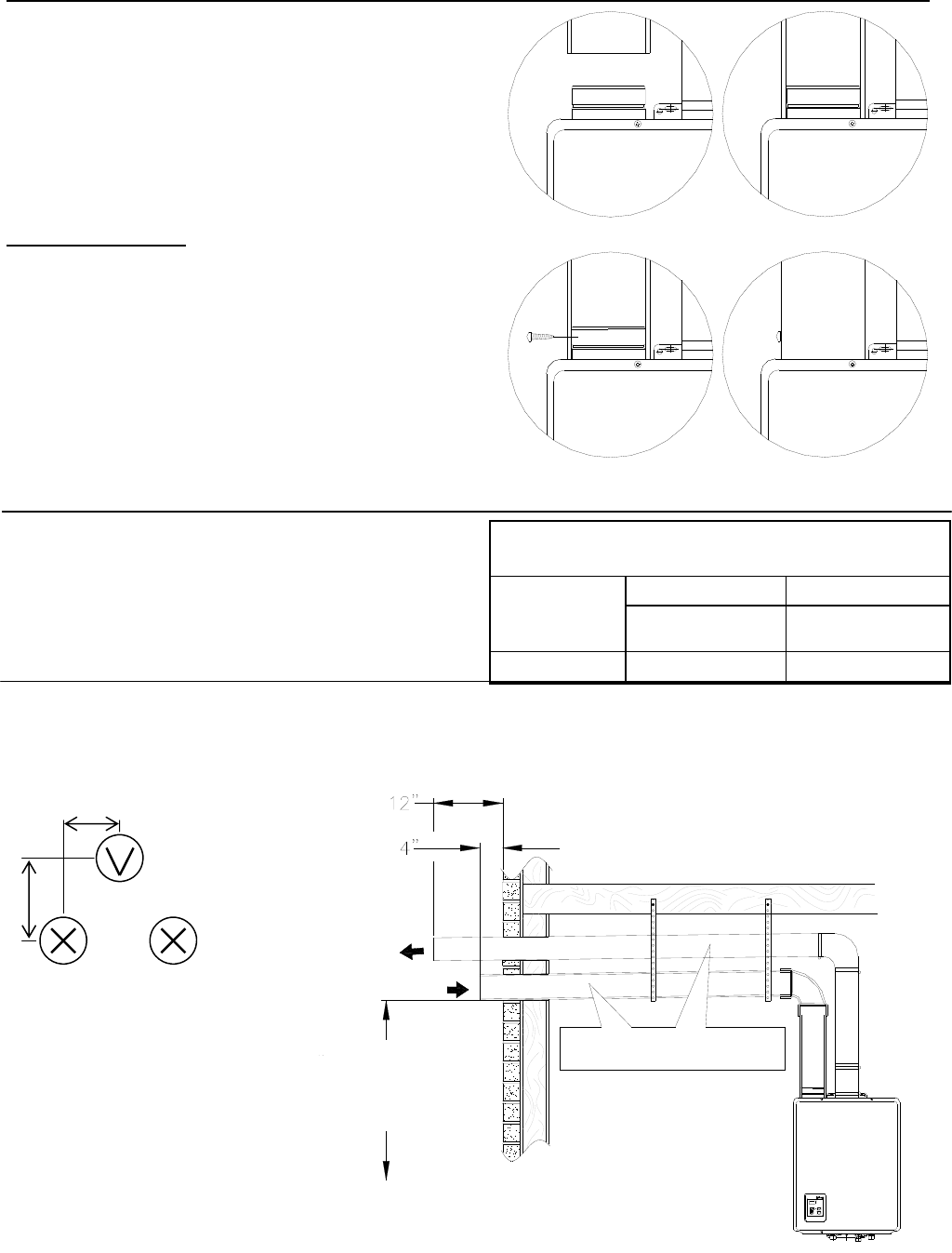
62 Manuel – Chauffe-eau d’intérieur série VB LS
Ensemble de prise d'air
Le système d'admission d'air consiste en un tuyau de
fourniture locale de 4 pouces de diamètre en acier inox, en
PVC, ABS ou CPVC catégorie 40. Un maximum de 6 pieds
de conduite semi flexible en aluminium peut être utilisée.
Une ventilation de sécheuse entouré de papier d'argent ou
des produits à corps cellulaire ne sont pas autorisés.
L'admission d'air a un espacement pouvant être nul par
rapport aux combustibles.
Connexion de prise d'air
1. Percez 2 petits trous en bout du tuyau d'admission d'air.
2. Glissez le tuyau par dessus le terminaison de prise
d'air.
3. En utilisant un niveau, assurez-vous que le tuyau est
bien droit.
4. Avec des vis autotaraudeuses, fixez le tuyau sur la
terminaison de prise d'air.
5. Appliquez un cordon de silicone autour du tuyau et de la
terminaison de prise d'air, afin d'assurer une connexion
étanche.
Montage du tuyau d'évacuation
Référez-vous aux instructions d'installation du constructeur
pour le système de ventilation d'évacuation spécifique.
4
3
12
COMBUSTION AIR /
INTAKE
EXHAUST
SLOPE INTAKE AND EXHAUST
TOWARD OUTSIDE TERMINATION
MINIMUM 1/4" PER FOOT
Terminaisons horizontales
L'admission d'air doit être située par rapport à l'évacuation comme illustré ci-dessous. L'arrivée d'air doit avoir une pente de
1/4" par pied afin d'éviter l'entrée de la pluie.
Installation de conduit de cheminée (R98LSi, R98LSi-ASME)
8”
6”
Entrée
Entrée
optionnelle
ÉVACUATION
La terminaison de ventilation et
l’entrée d’air doivent être dans la
même zone de pression.
Espacement de la ventilation par
rapport aux combustibles
Taille de
ventilation
Enfermée Non enfermée
Horizontale et
Verticale
Horizontale et
Verticale
4" (102 mm) 4" (102 mm) 1" (26 mm)
12" MINIMUM AU
DESSUS DU SOL OU DU
NIVEAU DE LA NEIGE
INCLINER ENTRÉE ET ÉVACUATION
VERS LA TERMINAISON EXTÉRIEURE
AU MINIMUM DE 1/4" PAR PIED
SORTIE
ENTRÉED'AIRDE
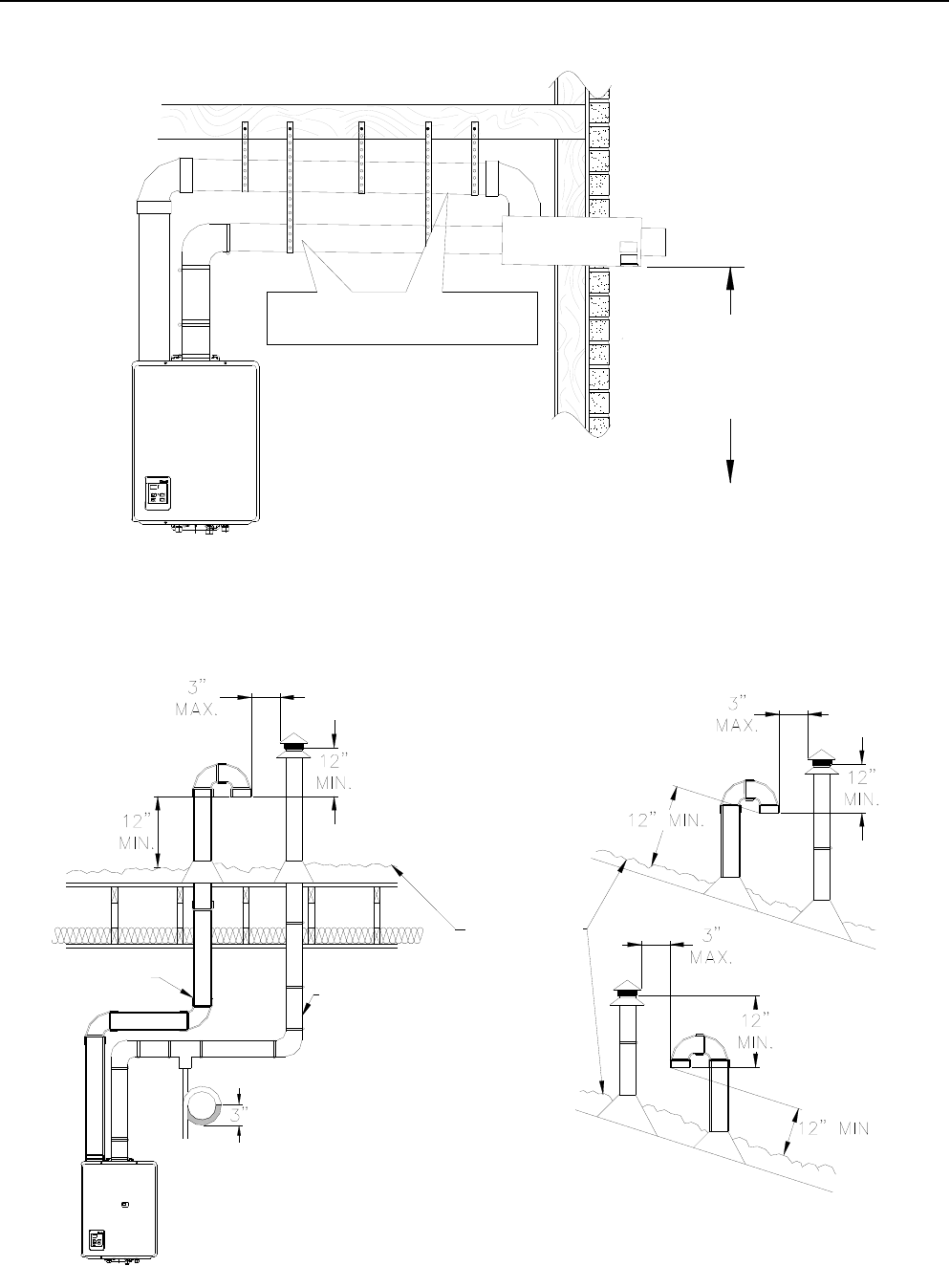
Manuel – Chauffe-eau d’intérieur série VB LS 63
Terminaisons verticales
L'admission d'air nécessite un coude en U ou deux couses à 90° pour éviter l'entrée de la pluie.
SLOPE INTAKE AND EXHAUST
TOWARD OUTSIDE TERMINATION
MINIMUM 1/4" PER FOOT
Terminaison horizontale concentrique
Installation de conduit de cheminée (R98LSi, R98LSi-ASME)
La terminaison de ventilation et l’entrée d’air doivent être dans la même zone de pression.
INCLINER ENTRÉE ET ÉVACUATION
VERS LA TERMINAISON EXTÉRIEURE
AU MINIMUM DE 1/4" PAR PIED 12" MINIMUM AU
DESSUS DU SOL OU DU
NIVEAU DE LA NEIGE
TUYAU D'ÉVACUATION
NIVEAU
ANTICIPÉ
DE LA NEIGE
TUYAU D'AIR
DE COMBUSTION
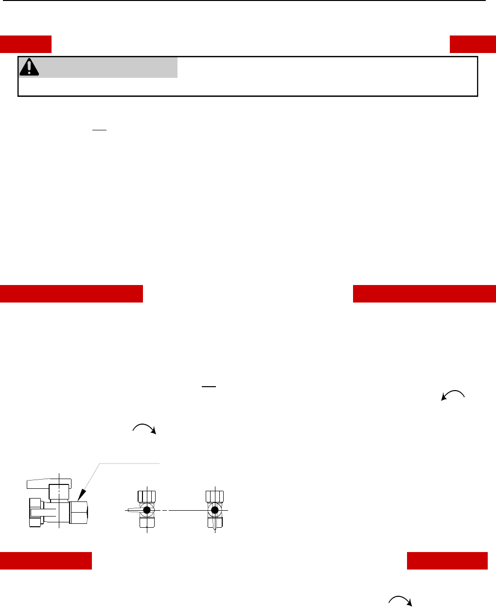
64 Manuel – Chauffe-eau d’intérieur série VB LS
Instructions d'utilisation
À LIRE AVANT LA MISE EN SERVICE POUR VOTRE SÉCURITÉ
A. Cet appareil ne comporte pas de veilleuse. Il est muni
d’un dispositif d’allumage qui allume automatiquement le
brûleur. Ne tentez pas d’allumer la veilleuse
manuellement.
B. AVANT DE FAIRE FONCTIONNER, reniflez tout autour
de l’appareil pour déceler une odeur de gaz. Reniflez
près du plancher, car certains gaz sont plus lourds que
l’air et peuvent s’accumuler au niveau du sol.
QUE FAIRE SI VOUS SENTEZ UNE ODEUR DE GAZ :
• Ne pas tenter d’allumer d’appareil.
• Ne touchez à aucun interrupteur ; ne pas vous servir
des téléphones se trouvant dans le bâtiment.
• Appelez immédiatement votre fournisseur de gaz
depuis un voisin. Suivez les instructions du
fournisseur.
• Si vous ne pouvez rejoindre le fournisseur, appelez le
service des incendies.
C. Ne poussez ou tournez la manette d’admission du gaz
qu’à la main ; ne jamais utiliser d’outil. Si la manette
reste coincée, ne pas tenter de la réparer ; appelez un
technicien qualifié. Le fait de forcer la manette ou de la
réparer peut déclencher une explosion ou un incendie.
D. N’utilisez pas cet appareil s’il a été plongé dans l’eau,
même partiellement. Faites inspecter l’appareil par un
technicien qualifié et remplacez toute partie du système
de contrôle et toute commande qui ont été plongés dans
l’eau.
COMMENT COUPER L’ADMISSION DE GAZ DE L’APPAREIL
1. Coupez l'alimentation électrique de l'appareil en utilisant
son bouton M/A.
2. Réglez le thermostat sur la consigne la plus basse.
3. Repérez la vanne de gaz manuelle sur le côté du
chauffe-eau. Fermez-la en la tournant à fond dans le
sens horaire (position OFF).
INSTRUCTIONS DE MISE EN MARCHE
1. ARRÊTEZ ! Lisez les instructions de sécurité sur la
portion supérieure (à gauche) de cette étiquette.
2. Réglez le thermostat sur la consigne la plus basse.
3. Coupez l'alimentation électrique de l'appareil en utilisant
son bouton M/A.
4. L'appareil est équipé d'un dispositif d'allumage qui
allume automatiquement le brûleur. Ne tentez pas
d’allumer la veilleuse manuellement.
5. Repérez la vanne de gaz manuelle sur le côté du
chauffe-eau. Fermez-la en la tournant à fond dans le
sens horaire (position OFF).
6. Attendre cinq (5) minutes pour laisser échapper tout le
gaz. Reniflez tout autour de l’appareil, y compris près du
plancher, pour déceler une odeur de gaz. Si vous sentez
une odeur de gaz, ARRÊTEZ ! Passez à l’étape B des
instructions de sécurité sur la portion supérieure (à
gauche) de cette étiquette. S’il n’y a pas d’odeur de gaz,
passez à l’étape suivante.
7. Ouvrez l'arrivée de gaz en tournant la vanne manuelle
de gaz en sens antihoraire (position ON).
8. Rétablissez l'alimentation électrique de l'appareil avec
son bouton M/A.
9. Passez le thermostat sur le réglage de consigne
souhaité.
10. Ouvrez un robinet d'eau chaude du circuit. Si l'appareil
ne démarre pas, suivez les instructions ci-dessous
relatives à la coupure du gaz vers l'appareil et appelez
un technicien de service ou votre fournisseur de gaz.
Reportez-vous au manuel pour plus d'informations.
CLOSE
Manual Valve
OPEN
AVERTISSEMENT
Si vous ne suivez pas exactement ces instructions, il peut en
résulter un départ d'incendie ou une explosion, causant dégâts
Vanne manuelle
FERMÉE OUVERTE
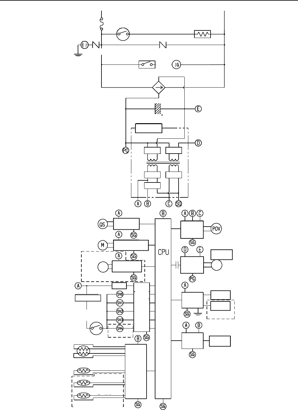
Manuel – Chauffe-eau d’intérieur série VB LS 65
Diagramme en escalier (RL75i, RL94i)
PHASE NEUTRE
CONTACT DE
DÉTECTION DE GEL
5 A
ANTI-FOUDRE
ANTI-FOUDRE
TERRE
VARISTOR VARISTOR
RELAIS 1 ALLUMAGE
ALIMENTATION À
DÉCOUPAGE
12 V CC
170 V CC
40 V CC
12,6 V
5 V CC
DÉTECTEUR
D'ÉCOULEMENT ÉLECTRO-
VANNE À
MODULATION
CIRCUIT D'ALIMENTA-
TION D'ÉLECTRO-
VANNE À
MODULATION
CIRCUIT
DÉTECTEUR
D'ÉCOULEMENT
DISPOSITIF DE CON-
TRÔLE D'ÉCOULEMENT
CIRCUIT DISPOSITIF DE
CONTRÔLE D'ÉCOULEMENT
CIRCUIT DE CONTRÔLE
D'ÉCOULEMENT DE
DÉRIVATION
MODÈLE D'INTÉRIEUR UNIQUEMENT
THERMISTANCE DE
TEMPÉRATURE D'AIR
CIRCUIT DE
THERMISTANCE
CIRCUIT DE
CONTRÔLEUR
À DISTANCE
CONTRÔLEUR À
DISTANCE
THERMISTANCE D'ÉCHAGEUR
THERMIQUE
THERMISTANCE DE
SORTIE D'EAU 1
INTERRUPTEUR
DE SURCHAUF-
FE
CIRCUIT DE
DÉTECTION DE
FLAMME
CIRCUIT DE
COMMANDE
D'ÉLECTRO-
VANNE
ÉLECTRODE
DE FLAMME 1
RELAIS 1 CIRCUIT DE
COMMANDE
DE RELAIS
DISPOSITIF DE
CONTRÔLE DÉ-
COULEMENT DE
CIRCUIT DE
COMMANDE DE
VENTILATEUR
VEBTILATEUR
DE COMBUS-
VENTI-LATEUR
UNITÉ
CENTRALE
DE
TRAITEMEN
T
FUS THER.
THERMISTANCE DE SORTIE
D'EAU 2
THERMISTANCE DE
BRÛLEUR
ÉLECTRODE
DE FLAMME 2
RL94 Séries UNIQUEMENT
Pour les modèles R98LSi et
R98LSiASME, consultez la page
suivante.
TERRE
M
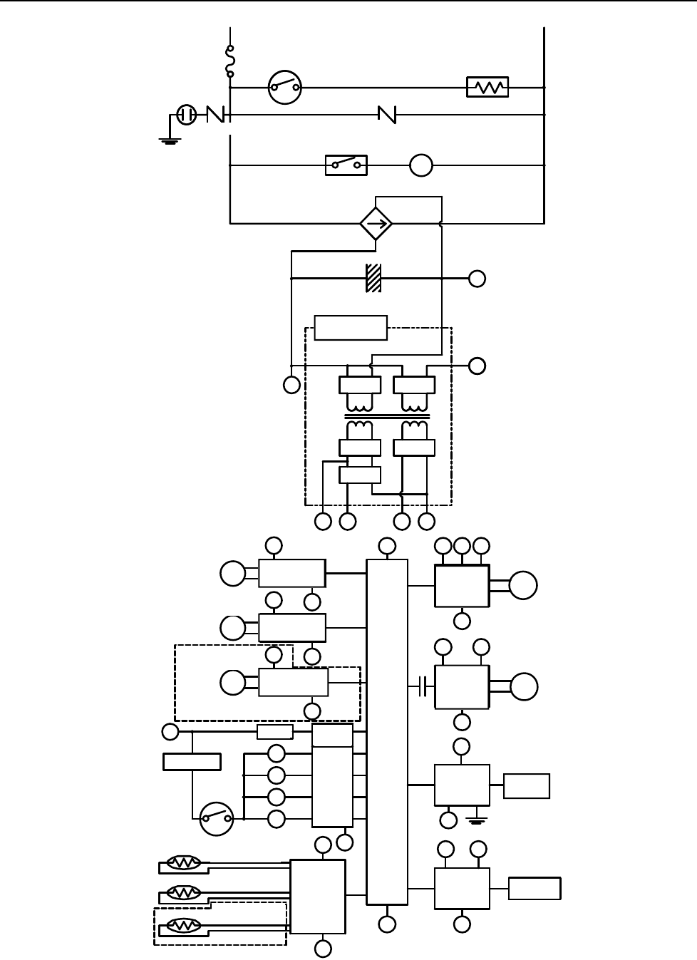
66 Manuel – Chauffe-eau d’intérieur série VB LS
Diagramme en escalier (R98LSi, R98LSiASME)
RELAY 1
IG
FROST SENSING
SWITCH
ANTI-FROST HEATER
IGNITION
COMBUSTION
FAN
3A(FUSE)
HOT NEUTRAL
VARISTOR
DC12.6V
SOLENOID
DRIVING
CIRC UIT
CPU
CENTRAL
PROCESSI NG
UNIT
FAN
REMOTE
CONTROLLER
POV
FAN
CONTROL
CIRCUIT
BY-PASS FLOW
CONTROL DEVI CE
CIRCU IT
THERMAL FUSE
OVER HEAT
SWITCH
MODULATING
SOLENOID
VALVE
DC40V
DC5V
A B C SG
SWITCHING
POWER SUPPLY
THERMISTOR
CIRCUIT
B
SG
RELAY 1
A
WATER FLOW
SENSOR
CIRCUIT
WATER FLOW
CONTROL DEVI CE
CIRC UIT
A
SG
A
SG
SG
A
QS
SG
FR
FLAME
DETECTING
CIRCUIT
FLAME ROD
GND
SG
A
REMOTE
CONTROLLER
CIRCUIT
A B
E
PG
ABC
SG
SG
B
VARI STOR
ARRESTER
GND
SG
WATER FLOW
SENSOR
WATER FLOW
CONTROL DEVI CE
BY-PASS FLOW
CONTROL DEVI CE
M
M
DC12V
DC170V
D
E
PG
SV3
SV2
SV1
SV0
RELAY
DRIVING
CIRCUI T
D
BY-PASS SERVOMODEL ONLY
OUTGOING WATER
THERMISTOR
HEAT EXCHANGER
THERMISTOR
AIR TEMPERATURE
THERMISTOR
INDOOR MODEL ONLY
MODULATING
VALVE POWER
CONTROL
CIRCUIT
PHASE NEUTRE
CONTACT DE
DÉTECTION DE GEL
3 A
ANTI-FOUDRE
ANTI-FOUDRE
TERRE
VARISTOR VARISTOR
RELAIS 1 ALLUMAGE
ALIMENTATION À
DÉCOUPAGE
12 V CC
170 V CC
40 V CC
12,6 V
5 V CC
DÉTECTEUR
D'ÉCOULEMENT ÉLECTRO-
VANNE À
MODULATION
CIRCUIT D'ALIMENTA-
TION D'ÉLECTRO-
VANNE À
MODULATION
CIRCUIT
DÉTECTEUR D'É-
COULEMENT
DISPOSITIF DE
CONTRÔLE D'É-
COULEMENT CIRCUIT DISPOSITIF
DE CONTRÔLE
D'ÉCOULEMENT
CIRCUIT DE CONTRÔLE
D'ÉCOULEMENT DE
DÉRIVATION
MODÈLE DE DÉVIATION SEULEMENT
MODÈLE D'INTÉRIEUR UNIQUEMENT
THERMISTANCE DE
TEMPÉRATURE D'AIR
CIRCUIT DE
THERMISTANCE
CIRCUIT DE
CONTRÔLEUR À
DISTANCE
CONTRÔLEUR À
DISTANCE
THERMISTANCE D'ÉCHA-
GEUR THERMIQUE
THERMISTANCE DE
SORTIE D'EAU
INTERRUPTEUR
DE SURCHAUF-
FE
CIRCUIT DE
DÉTECTION DE
FLAMME
CIRCUIT DE
COMMANDE
D'ÉLECTRO-
VANNE ÉLECTRODE
DE FLAMME
RELAIS 1 CIRCUIT DE
COMMANDE
DE RELAIS
DISPOSITIF DE
CONTRÔLE DÉ-
COULEMENT DE
CIRCUIT DE
COMMANDE DE
VENTILATEUR
VEBTILATEUR DE
COMBUSTION
VENTI-
LATEUR
UNITÉ
CENTRALE
DE
TRAITEMENT
FUS THER.
TERRE
Manuel – Chauffe-eau d’intérieur série VB LS 67
Support à la clientèle
Qu'est-ce qui est couvert ?
Cette garantie couvre tous défauts dus aux matériaux et à la main d'œuvre quand le produit a été installé et utilisé en suivant
les instructions écrites d'installation de Rinnai, dans les termes décrits dans ce document de garantie limitée. Cette garantie
s'applique seulement aux produits qui sont installés correctement. Une installation incorrecte pourrait annuler cette garantie.
Rinnai vous recommande fortement d'employer un installateur qui aura suivi une classe Rinnai pour la connaissance des
produits avant d'installer le chauffe-eau. Cette garantie couvre l'acheteur d'origine uniquement tant que le produit reste sur le
site de son installation initiale. Cette garantie ne joue qu'après la toute première installation du produit et se termine s'il est
déplacé ou réinstallé à un autre emplacement.
Combien de temps dure la couverture ?
Garantie limitée
Informations sur la garantie
L'installateur est responsable de l'installation correcte de votre chauffe-eau.
Veuillez fournir les informations demandées ci-dessous et les archiver :
Appareil acheté chez :: _________________________________________________________________
Adresse : _____________________________ Téléphone : _________________________________
Date de l'achat : __________________________________
Référence de modèle : ________________________________________
Numéro de série : ________________________________________
Installé par : ___________________________ N° d'immatriculation de l'installateur : _________________
Adresse : _____________________________ Téléphone : _________________________________
Date de l'installation: __________________________________
* Note : La période de couverture est réduite à 3 ans à partir de la date d'achat quand le chauffe-eau est utilisé comme chauffage
d'eau circulante dans une boucle de circulation d'eau chaude, où il est utilisé en série avec un système de circulation, et que
toute l'eau qui circule passe au travers de lui, et où un système de recirculation à la demande n'est pas incorporé.
Une recirculation à la demande est définie comme une boucle de recirculation d'eau chaude ou un système qui utilise des
conduites d'eau chaude et froide existantes, ou une conduite de retour dédiée, et qui ne s'active que lorsque de l'eau chaude
est utilisée. L'activation peut se faire par bouton poussoir, détecteur de mouvement ou activation vocale, mais pas par un
capteur de température. Une minuterie ajoutée sur une pompe de recirculation standard n'est pas considérée comme
donnant un système à la demande.
L'utilisation d'un contrôleur MCC-91 dans une habitation résidentielle réduira la couverture de garantie au niveau de la
garantie pour une application commerciale
† Note : La période de garantie est réduite à 5 ans à partir de la date d'achat si le réglage de température du chauffe-eau Rinnai
dépasse 160°F (71 °C).
Élément
Période de couverture (à partir de la date d'achat) pour Séries LS
Avec traitement d'air
Rinnai pour chauffage et
eau domestiques
Applications
commerciales incluant
chauffage radiant
Échangeur thermique 12 ans* 10 ans* † 5 ans*
Autre pièces et composants 5 ans* 5 ans* † 5 ans*
Main d'œuvre dans la limite du raisonnable 1 an
Applications
domestiques

68 Manuel – Chauffe-eau d’intérieur série VB LS
Que fait Rinnai pour exercer la garantie ?
Rinnai va réparer ou remplacer le produit, ou toute partie ou tout composant défectueux pour cause de matériaux ou de main
d'œuvre, dans les conditions définies plus loin. Rinnai remboursera des charges de main d'œuvre raisonnables associées
avec la réparation ou le remplacement de toute pièce ou tout composant. Toutes les pièces utilisées pour la réparation doivent
être des pièces Rinnai d'origine. Toutes les réparations et tous les remplacement doivent être effectués par un artisan ou du
personnel de société de service qui aura été convenablement formé et sera administrativement agréé pour effectuer ce type
de travail.
Le remplacement du produit complet ne peut être autorisé que par Rinnai. Rinnai n'autorise aucune personne ou entité à
assumer pour elle toute obligation ou responsabilité en relation avec le remplacement du produit. Si Rinnai détermine que la
réparation d'un produit n'est pas possible, Rinnai le remplacera par un produit comparable, à sa discrétion. Si un composant
ou un produit retourné à Rinnai est trouvé sans défaut du aux matériaux ou à la main d'œuvre, ou qu'il est déterminé qu'il a été
mal installé ou endommagé pendant l'expédition de retour, la réclamation au titre de la garantie pourra être rejetée.
Comment obtenir le service au titre de la garantie ?
Vous devez contacter un fournisseur de service qualifié/agréé pour la réparation d'un produit dans le cadre de cette garantie.
Pour trouver les coordonnées d'un tel fournisseur local, veuillez contacter votre point d'achat, ou allez sur le site Web de
Rinnai (www.rinnai.us). Vous pouvez aussi téléphoner à Rinnai au 1-800-621-9419 ou écrire à Rinnai : 103 International Drive,
Peachtree City, Georgia 30269, USA.
La preuve de votre achat est nécessaire pour bénéficier du service dans le cadre de la garantie. Vous pouvez montrer la
preuve de l'achat avec une facture ou un ticket de caisse datés, ou en vous enregistrant dans les 30 jours suivant l'achat du
produit. Veuillez remplir l'enregistrement en ligne sur www.rinnairegistration.com ou envoyez par la poste la carte
d'enregistrement de l'appareil à Rinnai (adresse imprimée sur la carte). Pour thos sans l'accès à Internet, s'il vous plaît appeler
1-866-RINNAI1 (746-6241) La réception de cette carte d'enregistrement servira de preuve de l'achat du produit. Cependant la
démarche d'enregistrement n'est pas une obligation pour valider cette garantie.
Qu'est-ce qui n'est pas couvert ?
Cette garantie ne couvre pas routes pannes ou difficultés de fonctionnement découlant de :
• accident, abus, mauvais usage
• altération
• application non prévue
• cas de force majeure
• installation incorrecte (comme sans y être limité mauvaise qualité de l'eau, dommages dus à la condensation, mauvaise
ventilation, type de gaz ou pression d'eau inadéquats, absence de bac de drainage sous l'appareil)
• entretien inadéquat (comme sans y être limité accumulation de tartre, dommages dus au gel, blocage de ventilation)
• mauvais dimensionnement de l’installation.
• ou pour toutes autres causes autres que des défauts dans les matériaux et la main d'œuvre
Cette garantie ne s'applique pas pour tout produit sur lequel numéro de série ou date de fabrication auraient été effacés. Cette
garantie ne couvre pas tout produit utilisé dans une application qui gère de l'eau traitée chimiquement, comme le chauffage de
piscine ou de spa. Cette appareil reste utilisable pour remplir de baignoires de grande contenance avec de l'eau potable.
Reportez-vous à la section relative à la qualité de l'eau dans le manuel d'installation et d'utilisation.
Limitation sur les garanties
Personne n'est autorisé a offrir toute autre garantie au nom de Rinnai America Corporation. Sauf pour ce qui est expressément
communiqué ici, il n'y a aucune autre garantie, explicite ou implicite, y compris sans y être limité les garanties de valeur
marchande ou d'adéquation à une finalité particulière, qui s'étendrait au-delà de la description de garantie fournie ici. De plus
Rinnai n'est pas responsable de tous dommages spéciaux, accessoires, indirects ou consécutifs qui peuvent survenir, y
compris les dommages aux personnes et aux biens, la perte d'usage, les désagréments ou les conséquences de mauvaise
qualité d'installation,entretien ou utilisation. Certains états ne permettent pas l'exclusion ou la limitation des dommages
annexes ou consécutifs, de ce fait la limitation qui précède peut ne pas être applicable à votre cas.
Toutes garanties implicites de valeur marchande et d'adéquation à une finalité spécifique autorisées par la législation locale
seront de toutes façons limitées en durée à la période de couverture offerte par cette garantie limitée, sauf si la période légale
locale d'application est plus courte. Certains états ne permettent pas de limitations sur le temps que durent les garanties
implicites, de ce fait la limitation qui précède peut ne pas être applicable à votre cas.
Cette garantie vous donne des droits légaux spécifiques, et vous pouvez également avoir d'autres droits qui peuvent varier
d'un état à l'autre.
Garantie limitée

VB Series Indoor LS Manual 69
Notes

70 VB Series Indoor LS Manual
Notes

VB Series Indoor LS Manual 71
Notes
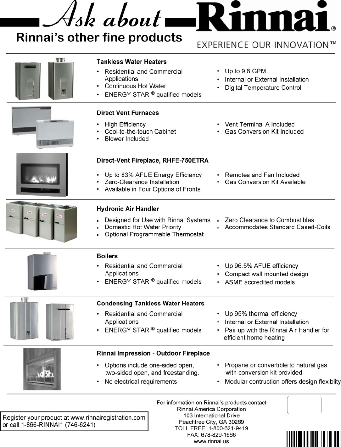
U287-1930
(00)
Printed in Japan
VB2528FFU
VB2735FFU
VA3237FFU
060 00012 32191 3
