Rinnai V75I Reu Vc2528Ffu Us Specification Sheet (VC2528FFU US) SP
2015-05-15
: Rinnai Rinnai-V75I-Reu-Vc2528Ffu-Us-Specification-Sheet-719903 rinnai-v75i-reu-vc2528ffu-us-specification-sheet-719903 rinnai pdf
Open the PDF directly: View PDF ![]() .
.
Page Count: 2
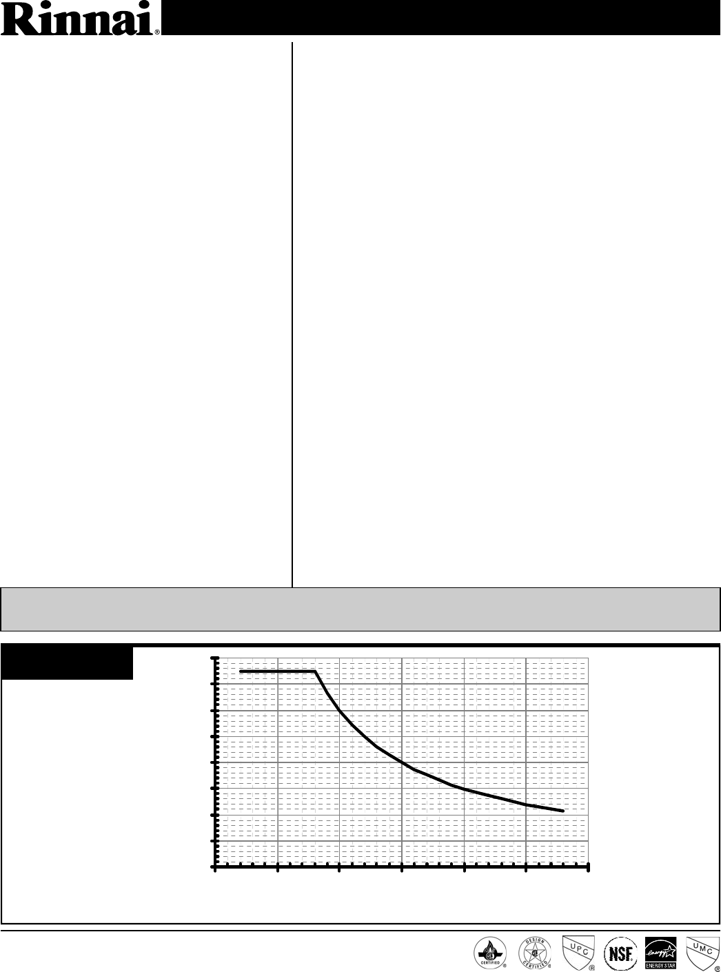
0.0
1.0
2.0
3.0
4.0
5.0
6.0
7.0
8.0
0 25 50 75 100 125 150
delta T - Temperature Rise (ºF)
Water Flow (gpm)
Type of Appliance
Rinnai Model Number
Minimum/Maximum Gas Rate (Input)
Electrical
Electrical Consumption
Ignition System
Hot Water Capacity
Temperature
Temperature (without remote)
Installation
Energy Factor
Service Connections
Water Flow Control
Minimum/Maximum Water Supply Pressure
• Temperature controlled, continuous flow, gas hot water system
• Certified for installation in manufactured (mobile) homes
• Forced combustion / Direct vent
• Energy Star qualified
REU-VC2528FFU-US
10,300 - 180,000 BTU/h
Appliance: AC 120 Volts - 60 Hz
Controller: DC 12 Volts
Normal: 76 w Standby: 2 w Anti-frost protection: 120 w
Direct electronic ignition
Minimum flow rate: 0.26 GPM
Minimum activation flow rate: 0.4 GPM
Maximum flow rate: 7.5 GPM
98° - 120° F (factory default) Maximum temperature is selectable at
120° F or at 140° F; 98° - 160° F available with the MCC-91-2
controller for hydronic applications
120° F (factory default) or 140° F
Indoor only
Natural Gas: 0.82 Propane: 0.82
Gas supply: 3/4 inch MNPT Cold water inlet: 3/4 inch MNPT
Hot water outlet: 3/4 inch MNPT
Water flow sensor, electronic water control device and fixed by-pass
20 - 150 PSI (recommended 30-80 PSI for maximum performance)
© 2012 Rinnai Corporation V75i SP 3/2012
FLOW TABLE
V75i (VC2528FFU-US)
Rinnai is continually updating and improving products; therefore, specifications are subject to change without prior
notice. Local, state, provincial and federal codes must be adhered to prior to installation.
Rinnai Corporation • 103 International Drive • Peachtree City, GA 30269 • Toll-Free: 1-800-621-9419 • Fax: 678-364-8643 • www.rinnai.us
Water Temperature Control
Controller
Controller Cable
Safety Devices
Clearances from Combustibles
(suitable for closet, attic, and
crawl space installations)
Clearances from Non-combustibles
Min. / Max. Gas Supply Pressure
(sea level)
Manifold Gas Pressure (inches W.C.)
NOx
Simulation feed forward and feedback
MC-91-2US (part of the front panel)
Deluxe controller: MC-100V-1US (optional)
Bathroom controller: BC-100V-1US (optional)
MCC-91-2US (optional; for hydronic applications)
Non-polarized two-core cable, minimum 22 AWG
• Flame failure - Flame Rod
• Boiling protection
• Combustion fan rpm check
• Over current - glass fuse
• Top of heater - 6 inches
• Front of heater - 6 inches
• Sides of heater - 2 inches
• Top of heater - 2 inches
• Front of heater - 6 inches
• Sides of heater - 1/2 inch
Natural Gas: min 5” W.C. max 10.5” W.C.
Propane Gas: min 8” W.C. max 13.5” W.C.
Natural Gas: high fire 2.5” W.C. low fire 0.61” W.C.
Propane Gas: high fire 3.9” W.C. low fire 0.87” W.C.
Complies with South Coast Air Quality Management District 14 ng/J
or 20 ppm NOx emission levels
• Remaining flame (OHS)
• Thermal fuse
• Automatic frost protection
• Back of heater - 0 inches
• Ground / bottom - 12 inches
• From vent pipe - 0 inches
• Back of heater - 0 inches
• Ground / bottom - 12 inches
• From vent pipe - 0 inches
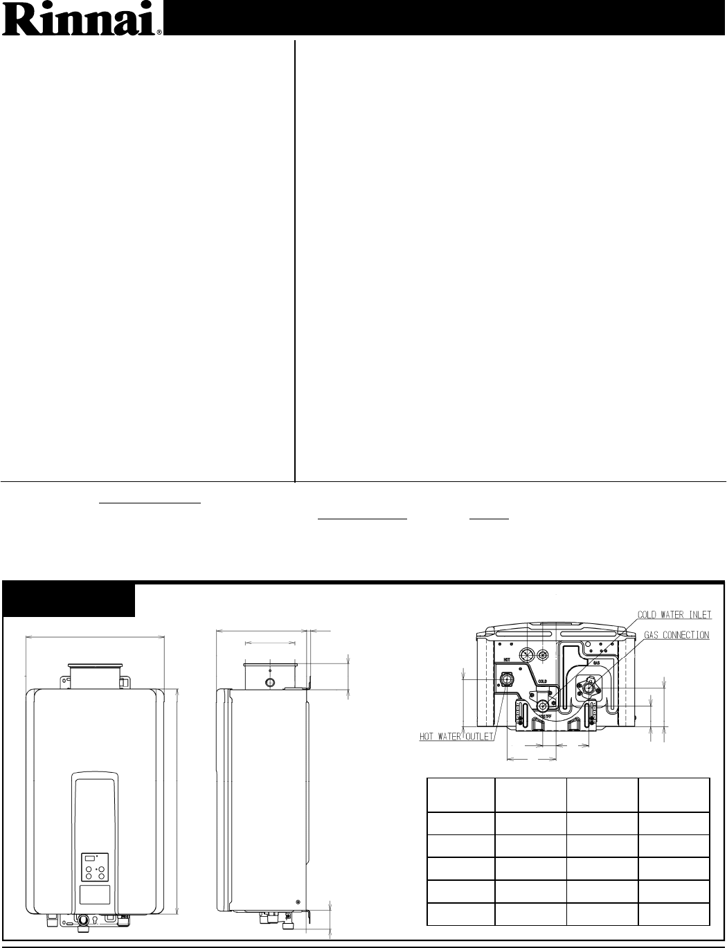
V75i (VC2528FFU-US)
B
C
D
E F G
0.4~1.8 (10~45) Variable
14.04 (356.6)
22.95 (583)
9.27 (235.5)
5.05 (128.1)
2.67 (67.8)
A
DIMEN-
SION Inches (mm) DIMEN-
SION Inches (mm)
A (GAS) 1.31 (33.2) D 4.33 (110)
A (COLD) 1.93 (49) E 2.89 (73.3)
A (HOT) 1.35 (34.4) F 1.85 (47)
B 4.21 (106.9) G 3.44 (87.3)
C 1.17 (29.8)
DIMENSIONS WEIGHT: 45.6 lb (20.7 kg)
Heat exchanger: 10 years* for residential and hydronic applications, increased to 12 years* if
installed with an isolation valve kit; All other parts: 5 years*; Labor: 1 year
(* reduced to 3 years if used as a circulating water heater within a circulation loop, when the water
heater is in series with a circulation system and all circulating water flows through the water heater)
Refer to the manual for complete warranty information.
Limited
Warranty
