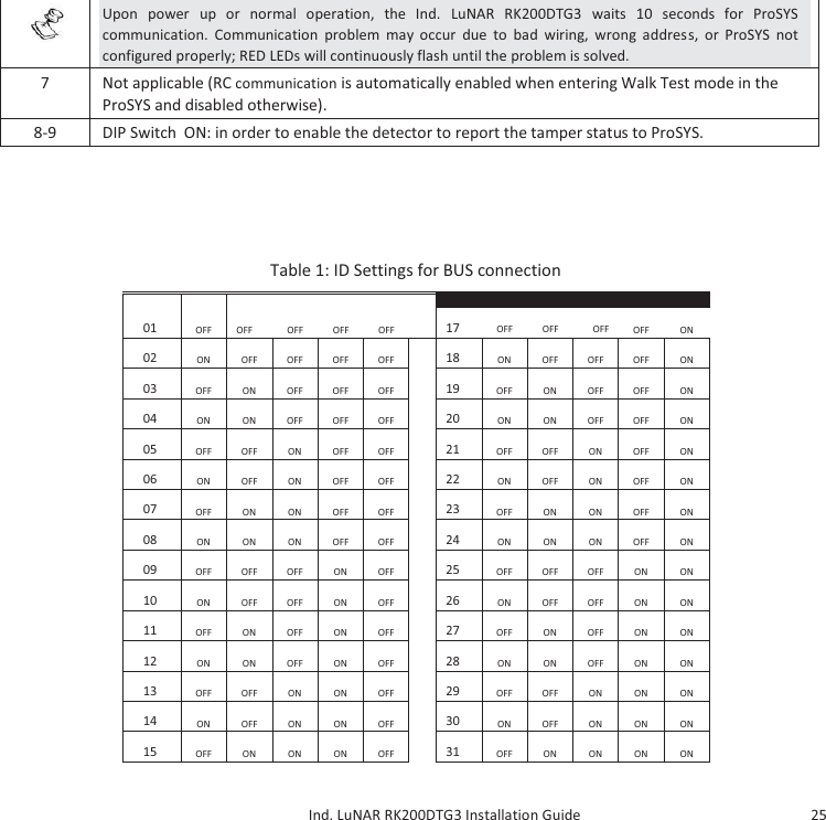
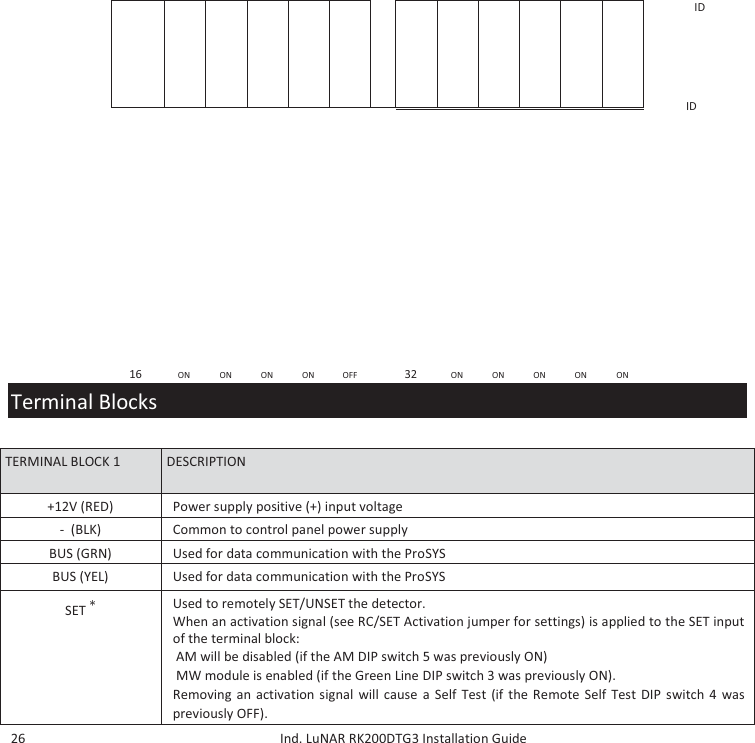
Risco RK200DTG3 Ind. LuNAR DT AM G3 User Manual CBB5C3F7CAE92E706466

Risco Ltd. Ind. LuNAR DT AM G3 CBB5C3F7CAE92E706466

User Manual

        D DDT T  A AAM M  G GGr rra aad dde e  3 3        H i g h   C e i l i n g   M o u n t   D e t e c t o r r  I n s t a l l a t i o n   G u i d e   M o d e l : R RK K2 0 0 D T G 3
                  DT AM Grade 3       Model: RK200DTG3            High Ceiling Mount Detector Installation Guide      General Description  The Industrial LuNAR DT AM Grade 3 (RK200DTG3) is a dual technology ceiling detector with a mounting height of up to 8.6m (28ft) that incorporates RISCO Group’s Anti-Cloak™ Technology (ACT™). The detector has an Intelligent Digital Signal Processing method that automatically adjusts the alarm threshold and pulse count verification according to actual intruder crossing speed and environmental factors, providing superior detection and false alarm immunity.   The Ind. LuNAR RK200DTG3 can operate as a regular relay detector connected to any control panel, or as an addressable BUS detector when connected to RISCO Group’s ProSYS control panel via the RS485 BUS.
      2     Ind. LuNAR RK200DTG3 Installation Guide  Ind. LuNAR RK200DTG3 Features  ♦  PD6662, EN50131-1, EN50131-2-4 Grade 3  ♦  Addressable Dual Technology detector with Anti-Cloak™ Technology  ♦  Up to 8.6 m (28ft) mounting height  ♦  3600 by 18m (60ft) diameter coverage pattern  ♦  3 independent PIR channels for customized coverage  ♦  Intelligent Digital Signal Processing – alarm verification and decision thresholds adjusted according to actual intruder crossing speed  ♦  Built-in Triple EOL resistors, jumper selectable  ♦  Active IR for Anti-Masking meeting EN50131 requirements  ♦  Ceiling and cover tampers   ♦  "Green Line" setting – for disabling the MW when the premises are occupied  ♦  Opto–relays for low current consumption and long life  ♦  Remote and Local Self Test   ♦  Remote SET input  ♦  Remote RC control input  ♦  PIR coverage optimization by sliding the lenses  ♦  Microwave Range Adjustment manually (analog trimmer) and remotely (digital setting)  ♦  Trouble Indication (by LEDs or via communication)  ♦  3 Triple color LEDs for easy walk testing  ♦  Advanced Remote control and diagnostics  ♦  Reduced Power Consumption when connected to RISCO Group’s ProSYS
    Ind. LuNAR RK200DTG3 Installation Guide   3  Remote Control and Diagnostic Features*   *Via the optional Bi-Directional Infrared Remote Control, or the ProSYS Upload/Download Software and Keypad.  Detection Method  The Ind. LuNAR RK200DTG3 detection is based on:    ♦ PIR (Passive Infra-Red) - which responds to changes in the IR radiation caused when an intruder crosses the protected area.  ♦ MW (Microwave) - which transmits signals and analyzes the frequency changes of the reflected echo from an intruder using Doppler Effect.   ALARM is initiated only when both technologies trigger simultaneously (except for certain situations in the ACT mode-see page 4 – “How ACT™ Works”), thus greatly reducing the possibility of false alarms.  How ACT™ Works  Anti-Cloak™ Technology (ACT™) provides the benefits of DT (Dual Technology) while avoiding its drawbacks.  This patent pending innovation has created a new standard for detectors. Dual Technology, a combination of PIR +MW, was an important development for the security industry...but, it has 2 major weaknesses:  IR emission blocking cloaks employed by intruders enable avoidance of detection.  PIR sensitivity is reduced when the protected area’s ambient temperature approaches body temperature.  Responding to requests from its customer base to solve these pressing problems, RISCO Group developed ACT™ -a revolutionary anti-cloak solution.  ♦  Remote microwave adjustment enables one-man walk test.  ♦  Diagnostic tools include detector input voltage reading and status of each PIR channel and MW channel (signal voltage and noise levels), AM channel (signal voltage), SW version verification.  ♦  Remote display and control of detector settings: MW adjustment, ACT on/off, LEDs on/off.  ♦  Remote trouble indication (Pass/Fail) for the PIR, MW and power supply input  ♦  Control of MW bypass (during MW trouble) and MW disable during Disarm ("Green Line") when connected to ProSYS.
       4     Ind. LuNAR RK200DTG3 Installation Guide  ACT™ prevents the alarm system from being bypassed, by neutralizing attempts to camouflage IR radiation. Using unique pattern recognition algorithms, ACT™ distinguishes between the weak IR signal of a moving intruder and the background noise and thermal interferences that may cause false alarms.  Once the presence of an intruder is recognized, ACT™ switches the system automatically from dual channel PIR/MW mode to single channel MW mode for a predetermined period of time, in order to trigger an alarm utilizing the MW channel, and then returns to dual channel mode.  In the second case, when the ambient temperature approaches body temperature, the ACT™ switches to microwave-only detection.  Offering significantly higher detection capabilities as well as immunity from false alarms, ACT™ thwarts even the most sophisticated burglars.                                 Ind. LuNAR RK200DTG3 Configuration Options  The Ind. LuNAR RK200DTG3 can be configured and/or diagnosed remotely via one of the options:
    Ind. LuNAR RK200DTG3 Installation Guide   5      Manual configuration  Remote  Control  Device  ProSYS Bus Control  ACT Mode     LEDs     MW Sensitivity  (by trimmer)    Diagnostics  -    Status/Trouble/Info Reports -    AM Diagnostics -  -   MW Bypass  -  -   MW Disable on Disarm ("Green Line")  -  -          LED Display    The three Tri color LEDs in the Ind. LuNAR RK200DTG3, operate as herein described:
       6     Ind. LuNAR RK200DTG3 Installation Guide  LED  STATE MEANING Red  Steady  Detector alarm (simultaneous PIR and MW detection)  Flashing with low frequency  Indicates malfunctioned communication with ProSYS  Flashing with high frequency  AM detection  Green  Steady  Microwave detection  Flashing  Trouble in the MW channel  Orange  Steady  PIR detection  Flashing  Trouble in the PIR channel  All LEDs  Flashing with change of color  Upon power up        INSTALLATION  Preliminary steps:  ♦  Before installation, study the space to be protected carefully in order to choose the exact location of the unit for the best possible coverage.  ♦  Never install the Ind. LuNAR RK200DTG3 in an environment that causes an alarm condition in one technology.   ♦  Avoid installations where rotating machines (e.g. fans) are normally in operation within the coverage pattern. Point the unit away from glass exposed to the outdoors and objects that may change temperature rapidly.  ♦  Do not mount the detector in direct sunlight or near any heat sources. Detection sectors should be pointed either towards a wall, floor but not towards windows or curtains. The installation surface should be solid, smooth and vibration free  ♦  Eliminate interference from nearby outside sources.
    Ind. LuNAR RK200DTG3 Installation Guide   7  ♦  For optimum detection, select a location likely to intercept an intruder moving across the coverage pattern.  ♦  Recommended mounting heights that allow 18m (60ft) detection, are from 3.7m to 8.6m.   ♦  The detector must be mounted on the ceiling, preferably in the center of the room.    Typical Ind. LuNAR RK200DTG3 detection coverage and installation height, are illustrated below:
       8     Ind. LuNAR RK200DTG3 Installation Guide    NOTE:  When installing the Ind. LuNAR RK200DTG3 detector in a room occupied with high volume interfering elements, MW detection may be affected.
    Ind. LuNAR RK200DTG3 Installation Guide   9
 10     Ind. LuNAR RK200DTG3 Installation Guide        Installation Process:     To open the detector (Figure 1), remove the cover by inserting a screwdriver (1) in the recess between the detector’s protection cap and the cover. The cover will remain attached to the base of the detector.    Using a Philips screwdriver, release the upper cover screw (2) and gently pull upward the detector’s upper cover.
    Ind. LuNAR RK200DTG3 Installation Guide   11   Release the PCB holding screw (Figure 2) located on the right hand side of the PCB (1), pull gently the two release clips (2) outward and remove the PCB.        (1   1122
 12     Ind. LuNAR RK200DTG3 Installation Guide  Do not touch the PIR    sensors! Do not remove  the white filters from their  position! They are essential for  correct operation  of the detector.          If required, open (Figure 3) the wiring channels knockout using a cutter (1, 2) and knockout holes in the rear cover (3, 4) using a screwdriver.
    Ind. LuNAR RK200DTG3 Installation Guide   13
 14     Ind. LuNAR RK200DTG3 Installation Guide  Insert the cable via the cable opening (Figure 4) and connect the desired wires as described in “Step 4- Wiring”.
    Ind. LuNAR RK200DTG3 Installation Guide   15     Return the PCB to its previous location and verify that it is well secured by the holding clips and the screw.
 16     Ind. LuNAR RK200DTG3 Installation Guide  Perform lens adjustment and DIP switch settings as described in “Lens Adjustment” on page 12 and on page 15.   Mount the top cover on the detector’s base.   Tighten the top cover’s central screw.  Replace the detector’s protection cap.    NOTE:  For a ceiling tamper, affix the back tamper screw as shown in Figure 5.      Lens Adjustment:  The Ind. LuNAR RK200DTG3  has three - Fresnel lenses attached to the cover, located in sensor protective sleeves. Adjust the position of the lenses based on the ceiling mounting height as follows:   Press the 2 clips attaching the sleeve (Figure 6) to the detector’s cover, and gently pull out the sleeve.       FIGURE 6
    Ind. LuNAR RK200DTG3 Installation Guide   17      Remove the lens from the sleeve (Figure 7) by gently lifting it from the holding pins that secure it to the sides of the sleeve.    FIGURE 7     Place the two pins, which are located on both sides of the sleeve into the matching slots on the lens. Use the following table to select the desired lens position.
 18     Ind. LuNAR RK200DTG3 Installation Guide        Return the protective sleeve back into place on the detector front cover.  Repeat steps 1 to 5 for the remaining 2 lenses.    NOTES:  Below 3.7m mounting height, the coverage diameter starts decreasing, and at 2.7m height coverage diameter is 15m (50ft). For customized coverage, it is possible to set the position of each lens to a different height, according to the installation conditions.
     Ind. LuNAR RK200DTG3 Installation Guide   19    Selectors and Jumpers
 20     Ind. LuNAR RK200DTG3 Installation Guide    RC/SET INPUT  Used to determine the polarity of the external inputs.    12V: 12v has to be connected in order activate the function.   GND or N.C. has no influence on the RC/SET status.   (see Relay mode DIP switches configuration)    0V: The GND has to be connected in order to activate the function.   12v or N.C. has no influence on the RC/SET status.  (see Relay mode DIP switches configuration)
    Ind. LuNAR RK200DTG3 Installation Guide   21  EOL RESISTORS  JUMPERS   The jumpers are used when connecting the detector to a DEOL or TEOL Zone. The jumpers allow the selection of TAMPER, ALARM E.O.L resistors (1K, 2.2K, 4.7K, 5.6K or 6.8K), according to the control panel settings. An additional double jumper allows the connection of 12K FAULT/AM E.O.L resistor (see EOL Resistors Schematic).  Follow the terminal block connection diagram when connecting the detector to a Double/Triple  End Of Line (DEOL/TEOL) Zone
 22     Ind. LuNAR RK200DTG3 Installation Guide  DIP Switch  Settings   The Ind. LuNAR RK200DTG3 has a 9 position DIP switch that changes functionality for use in Relay mode or in BUS operation mode. Set the DIP switch according to the tables below:     ON Factory Default Settings:                                  1  2 3 4 5 6 7  8 9
     Ind. LuNAR RK200DTG3 Installation Guide   23  Relay Mode Configuration (DIP switch 6=OFF):    DIP switch    Description Number   Green Self  RELAY REMOTE ACT LED AM  N/A N/A Line  Test MODE CONTROL ON  1  2 3 4 5 6 7 8  9   1 Used to determine the operation of the ACT   DIP switch ON: ACT is enabled   DIP switch OFF: ACT is disabled (default factory)  2 Used to determine the operation of the detector’s LEDs Dip switch ON: LEDs are enabled (default factory)  DIP switch OFF: LEDs are disabled   3 Used to determine the operation  of the "Green Line" (See Note below)  DIP switch ON: "Green Line" is enabled  DIP switch OFF: "Green Line" is disabled (default factory)  4 Used to determine the type of Self Test (See Note below) DIP switch ON: Local Self Test:   In case the local self test fails, the FAULT/AM Relay is activated for a period of 2.5 secs. DIP switch OFF: Remote Self Test (default factory):   In case the remote self test passes, the Alarm Relays are activated for a period of 5 secs.  In case the test fails, FAULT/AM Relay is activated for a period of 2.5 seconds.  5 Used to determine whether Active IR Anti-Masking is active. (See Note below)  DIP switch ON: Enable  DIP switch OFF: Disable (default factory)  IMPORTANT:  If the AM is enabled via DIP Switch 5, the cover must be fitted within 1 minute from applying the power. If the detector is already powered up and DIP Switch 5 is turned on, the unit must be down powered to reset the AM calibration.  6 Used to determine the detector’s connection mode DIP switch OFF: Relay mode  Used to determine if the Remote Control communication is enabled or disabled.
 24     Ind. LuNAR RK200DTG3 Installation Guide  DIP switch ON: RC communication is always enabled. DIP switch OFF: RC communication depends on the voltage applied to the terminal block 7   “RC” (default factory)  When an activation signal is applied to the RC input of the terminal block, RC is enabled.  IMPORTANT:  Turn dipswitch 7 “OFF” after installation and when leaving the site for security reasons.  This will prevent unauthorized use of a remote control unit that may be used to disable the detector.   8-9    DIP switches OFF NOTE:      See Set Terminal Blocks for activation details.     BUS Mode Configuration (DIP   BUS  BUS ADDRESS  TAMPER MODE switch  6=ON):           DIP switch  Number  Description  1-5  Used to set the detector ID number. (See Table 1)  Set the ID number in the same way as for any other ProSYS accessory.   6  Used to determine the detector’s connection mode.  DIP switch  ON: ProSYS connection – BUS configuration NOTE:
     Ind. LuNAR RK200DTG3 Installation Guide   25     Upon power up or normal operation, the Ind. LuNAR RK200DTG3 waits 10 seconds for ProSYS communication. Communication problem may occur due to bad wiring, wrong address, or ProSYS not configured properly; RED LEDs will continuously flash until the problem is solved.   7  Not applicable (RC communication is automatically enabled when entering Walk Test mode in the ProSYS and disabled otherwise).  8-9  DIP Switch  ON: in order to enable the detector to report the tamper status to ProSYS.       Table 1: ID Settings for BUS connection  01  OFF  OFF   OFF   OFF   OFF     17   OFF   OFF   OFF  OFF  ON  02  ON  OFF  OFF  OFF  OFF                        18  ON  OFF  OFF  OFF  ON  03  OFF  ON  OFF  OFF  OFF  19  OFF  ON  OFF  OFF  ON  04  ON  ON  OFF  OFF  OFF  20  ON  ON  OFF  OFF  ON  05  OFF  OFF  ON  OFF  OFF  21  OFF  OFF  ON  OFF  ON  06  ON  OFF  ON  OFF  OFF  22  ON  OFF  ON  OFF  ON  07  OFF  ON  ON  OFF  OFF  23  OFF  ON  ON  OFF  ON  08  ON  ON  ON  OFF  OFF  24  ON  ON  ON  OFF  ON  09  OFF  OFF  OFF  ON  OFF  25  OFF  OFF  OFF  ON  ON  10  ON  OFF  OFF  ON  OFF  26  ON  OFF  OFF  ON  ON  11  OFF  ON  OFF  ON  OFF  27  OFF  ON  OFF  ON  ON  12  ON  ON  OFF  ON  OFF  28  ON  ON  OFF  ON  ON  13  OFF  OFF  ON  ON  OFF  29  OFF  OFF  ON  ON  ON  14  ON  OFF  ON  ON  OFF  30  ON  OFF  ON  ON  ON  15  OFF  ON  ON  ON  OFF  31  OFF  ON  ON  ON  ON
 26     Ind. LuNAR RK200DTG3 Installation Guide      ID  1  2 3 4 5 ID  1  2 3 4 5  16   ON   ON   ON   ON   OFF      32   ON   ON   ON   ON   ON  Terminal Blocks     TERMINAL BLOCK 1  DESCRIPTION  +12V (RED)  Power supply positive (+) input voltage  -  (BLK)  Common to control panel power supply  BUS (GRN)  Used for data communication with the ProSYS  BUS (YEL)  Used for data communication with the ProSYS  SET כ    Used to remotely SET/UNSET the detector.   When an activation signal (see RC/SET Activation jumper for settings) is applied to the SET input of the terminal block:    AM will be disabled (if the AM DIP switch 5 was previously ON)    MW module is enabled (if the Green Line DIP switch 3 was previously ON).  Removing an activation signal will cause a Self Test (if the Remote Self Test DIP switch 4 was previously OFF).
     Ind. LuNAR RK200DTG3 Installation Guide   27  RC כ  (REMOTE  CONTROL)    Used to enable/disable the remote control communication, only when DIP switch 7 is “OFF”.  When an activation signal (see RC/SET input jumper for settings) is applied to the RC input of the terminal block, Remote Control will be enabled.  Note: DIP switch 7 “ON” constantly enables RC communication.    WARNING:  Turn DIP switch 7 “OFF” after installation and when leaving the site for security reasons.  This will prevent unauthorized use of a remote control unit that may be used to disable the detector.   כ  Not relevant in BUS mode          TERMINAL BLOCK 2  DESCRIPTION  AM/FAULT  Normally closed output  The AM/FAULT output opens in the following events:   Detector is masked (ALARM also opens in this case)   Self Test failed   Input voltage is low (6VDC-8VDC)  TAMPER  Normally closed output  ALARM  Normally closed output
      28     Ind. LuNAR RK200DTG3 Installation Guide  Walk Test     NOTE:  To perform the walk test, first enable the LEDs.      Two minutes after applying power (warm-up period), walk test the detector over the entire protected area to verify proper operation of the detector and observe the Tri - color LED. The edge of the microwave pattern is determined by the first red LED activation (both PIR and MW LEDs are triggered).    NOTE:  If the PIR/MW LEDs do not TURN ON, probably it means that there is a problem with either the lens (PIR) position, or MW adjustment!    Adjust the microwave sensitivity by turning the PCB potentiometer (using a screwdriver), or by using the Remote Control device. Walk test the unit from all directions to determine all the detection pattern boundaries.      NOTE:  Adjust the MW to the lowest possible setting that will still provide enough coverage for the entire protected area!
     Ind. LuNAR RK200DTG3 Installation Guide   29    When using the Remote Control device, it is recommended to perform the LuNAR Self Test; for further instructions refer to the Remote Control Instructions.  Upon completion of installation and testing stages, ensure that all switches are in their desired positions.  IMPORTANT:  Turn DIP switch 7 “OFF” after installation and when leaving the site for security reasons.  This will prevent unauthorized use of a remote control unit, that may be used to disable the detector.    Troubleshooting  This section describes possible system problems and their solutions:  Always perform the following preliminary checks before referring to the troubleshooting table:
      30     Ind. LuNAR RK200DTG3 Installation Guide  Perform a complete visual inspection of the Ind. LuNAR RK200DTG3, for signs of mechanical damage, loose connections or torn wires.  Check the connections of the incoming AC power source.  Trouble  Meaning  Response  ProSYS Configuration of detectors fails/not accepted by the system  ID configuration problem  Disconnect all power sources, configure the desired IDs and reconnect power again Tamper indication while working in the BUS mode  Tamper connection malfunction Verify that both DIP 8 and 9 are in ON position
     Ind. LuNAR RK200DTG3 Installation Guide   31  Tamper indication in the Relay or BUS mode  Tamper probably not closed Visually verify that ceiling tamper and spring are correctly installed Walk test cannot be initiated via the ProSYS keypad   Wrong code   Insert the appropriate code  Green LED doesn’t operate during Walk test - MW channel does not function  Ind. LuNAR RK200DTG3 is configured (via the ProSYS) to the “MW disable on DISARM”  during  ProSYS’s  DISARM mode  Normal behavior    Ind. LuNAR RK200DTG3  operating in Bypass mode due to “Bypass MW channel mode”  Reset the detector.  If MW channel trouble reoccurs, replace the detector with a new one  Specifications  Coverage    Coverage pattern consists of 192 fingers (96 Fresnel facets) divided into 3 lens sections.   Each lens section has 4 adjustable vertical positions for variable mounting height and customized coverage.  360° by 18m (60ft) diameter. When mounting the detector under  3.7m, the coverage diameter starts to decrease up to 15m (50ft).  Variable Mounting Height  From 2.7m to 8.6m (9’ to 28’), 4 lens positions according to installation height  RFI immunity  According to EN50130-4
      32     Ind. LuNAR RK200DTG3 Installation Guide  Operating voltage  9 to 16VDC  Current consumption  20mA at 12VDC, 30mA at 16 VDC, Maximum 40mA with all LEDs on.  Alarm and AM contacts  Opto-relay NC, 100mA, 24 VDC   Tamper contacts  NC, 500mA, 24 VDC  Alarm Time  2.2 seconds  Warm-up time  2 minutes  Optical Filtering for white light      protection  Pigmented Fresnel lens  Operating temperature  -20° C to 55° C (-4° F to 131° F)  Storage temperature  -20° C to 60° C (-4° F to 140° F)  Dimensions (Height x Diameter)    99mm x 194mm (3.9’’x 7.6’’)    The Ind. LuNAR RK200DTG3 detector is suitable for use in installations complying with PD6662, EN50131-1 and EN501312-4 Grade 3, Class II.
   DT AM Grade 3       Modello: RK200DTG3                     Rivelatore da Soffitto     Manuale di Installazione      Descrizione Generale  Il LuNAR industriale DT AM Grado 3 (RK200DTG3) è un rivelatore doppia tecnologia da soffitto che può essere installato fino ad una altezza di 8.6 metri e integra la rivoluzionaria tecnologia Anti-Cloak™ Technology (ACT™) di
  2 RISCO. Il rivelatore ha un’intelligente elaborazione digitale del segnale che configura automaticamente le soglie di allarme e il conteggio degli impulsi in funzione del movimento dell’intruso all’interno dell’area protetta rispetto ai fattori ambientali, garantendo la migliore rivelazione possibile.  Il Ind. LuNAR RK200DTG3 può funzionare sia come unità “stand alone”, collegabile a qualsiasi centrale d’allarme, sia come Accessorio BUS, collegabile via BUS RS-485 ai sistemi d’allarme RISCO serie ProSYS.  Caratteristiche del Ind. LuNAR RK200DTG3  ♦  Conforme alle normative europee PD6662, EN50131-1, EN50131-2-4 Grado 3  ♦  Rivelatore doppia tecnologia indirizzato con tecnologia Anti-Cloak™   ♦  Installazione fino a 8.6 metri di altezza  ♦  Copertura di 3600 con 18 metri di diametro  ♦  3 rivelatori PIR indipendenti per una copertura programmabile  ♦  Elaborazione Digitale del Segnale – verifica dell’allarme e modifica delle soglie di allarme in funzione del movimento dell’intruso all’interno dell’area protetta  ♦  Resistenze di fine linea selezionabili tramite ponticelli  ♦  IR attivo Anti-Mask conforme alle specifiche tecniche europee EN50131  ♦  Interruttori antimanomissione contro l’apertura e la rimozione  ♦  Configurazione "Green Line" per disabilitare le emissioni della sezione microonda ad impianto disinserito  ♦  Relè opto isolati a basso assorbimento di corrente e lunga durata  ♦  Auto-test locale o remoto tramite comando remoto   ♦  Ingresso di stato impianto inserito/disinserito (SET)   ♦  Ingresso per l’abilitazione del dispositivo di controllo remoto (RC)    ♦  Ottimizzazione della copertura PIR tramite lo spostamento delle Lenti  ♦  Portata Microonda regolabile manualmente tramite potenziometro (regolazione analogica) e in remoto (regolazione digitale)  ♦  Indicazione di anomalia  (tramite LED o in remoto)
    Ind. LuNAR RK200DTG3 - Guida all’installazione   3  ♦  3 LED con tricolore per effettuare agevolmente la prova di copertura  ♦  Controllo e diagnostica remota avanzata  ♦    Limitazione dell’assorbimento in corrente se collegato ai sistemi d’allarme ProSYS   Ind. LuNAR RK200DTG3 - Guida all’installazione  Caratteristiche di Controllo e Diagnostica Remota*  ♦ Regolazione remota della microonda.  ♦ Le utilità di diagnostica includono la lettura della tensione di alimentazione del rivelatore, lo stato dei 3 canali PIR (Infrarosso) e del canale MW (microonda) (tensione del segnale e livelli di rumore) e la verifica della versione del firmware.  ♦ Visualizzazione remota e controllo della configurazione dell’unità per quanto riguarda la regolazione della microonda, l’ACT (on/off) e i LED (on/off).  ♦ Indicazione remota di anomalia per la sezione PIR, MW e l’ingresso di alimentazione.   ♦ Controllo ed esclusione microonda MW (in caso di anomalia MW) e disabilitazione microonda MW durante il periodo in cui l’impianto d’allarme è disinserito (funzione “Green Line”), se collegato via bus ai sistemi d’allarme ProSYS.  *Tramite il dispositivo bidirezionale di controllo all’infrarosso (opzionale) o il software di  teleassistenza se l’unità è collegata via BUS ad un sistema d’allarme ProSYS.   Sistema di Rilevazione  La rilevazione del Ind. LuNAR RK200DTG3 si basa sulle seguenti tecnologie:   ♦ PIR (Infrarosso Passivo) – rileva il cambiamento di temperatura che viene generato da un intruso che attraversa l’area protetta dal sensore.
  4  ♦ MW (Microonda) – trasmette segnali e analizza la variazione di frequenza degli stessi causata da un intruso che si muove all’interno dell’area protetta. Questa tecnologia lavora con il principio dell’effetto Doppler.   L’ALLARME viene generato solo quando entrambe le tecnologie di rilevazione vengono attivate simultaneamente (ad eccezione del funzionamento con ACT – consultare la pagina 4 – “Come funziona l’ACT™”), riducendo drasticamente la percentuale di allarmi impropri.
 5     Ind. LuNAR RK200DTG3 - Guida all’installazione     Come funziona l’ACT™  Anti-Cloak™ (ACT™) è la prima vera innovazione della tecnologia di rivelazione volumetrica antintrusione dall'introduzione della tecnologia ad Infrarosso Passivo. Offrendo i benefici di un rivelatore a Doppia Tecnologia ma allo stesso tempo sopperendo ai suoi punti deboli, questa innovazione, in attesa di brevetto, costituisce un nuovo standard nella tecnologia dei rivelatori antintrusione.  I rivelatori a doppia tecnologia Microonda e Infrarosso Passivo sono stati un importante sviluppo per l'industria della sicurezza per la loro capacità di riduzione degli allarmi impropri. Essi però hanno due grandi punti deboli:  Gli intrusi possono evitare di essere rilevati dal canale IR bloccando le radiazioni infrarosse del proprio corpo con un grosso ombrello, un cartone o altro.  La sensibilità del PIR si riduce notevolmente quando vengono protette aree in cui la temperatura ambientale raggiunge quella del corpo umano.  In risposta alle richieste dei clienti di risolvere queste problematiche, RISCO ha sviluppato la rivoluzionaria tecnologia chiamata ACT™.  ACT™ previene la neutralizzazione del sistema di allarme quando il canale all'infrarosso dei normali rivelatori a doppia tecnologia viene messo in condizione di non rilevare un intruso. Utilizzando algoritmi che analizzano la forma d'onda e la frequenza dei segnali infrarossi, ACT™ identifica il segnale particolarmente basso di un intruso in movimento rispetto ad interferenze termiche che potrebbero essere causa di allarmi impropri.  Una volta che la presenza di un intruso è stata rilevata, ACT™ commuta automaticamente il rivelatore da doppia tecnologia al funzionamento in solo Microonda per un periodo di tempo determinato al fine di attivare l'allarme con il solo canale Microonda.  Nel secondo caso, quando la temperatura dell'ambiente protetto si avvicina alla temperatura del corpo umano, ACT™  commuta in microonda singola.  ACT™ garantisce rilevazione dell’intruso anche in condizioni critiche ed elevata immunità ai falsi allarmi.
 6     Ind. LuNAR RK200DTG3 - Guida all’installazione       Opzioni di Configurazione del Ind. LuNAR RK200DTG3  Il Ind. LuNAR RK200DTG3 può essere configurato e/o testato in remoto tramite le opzioni elencate nella tabella che segue:      Locale sul rivelatore   Dispositivo Remoto  Da centrale ProSYS  Modo ACT     Abilitazione LED    Sensibilità MW   (via trimmer)    Diagnostica  -    Stato/Anomalie/Informazioni -    Diagnostica AM -  -   Esclusione MW se in anomalia   -  -   Disabilita MW in disinserito (Funzione "Green Line")  -  -
    Ind. LuNAR RK200DTG3 - Guida all’installazione   7  Indicatori LED  I tre LED tricolori del Ind. LuNAR RK200DTG3, riportano le informazioni che seguono:   LED  STATO SIGNIFICATO Rosso  Acceso  Rivelatore in allarme (rilevazione   simultanea su canale PIR e MW)  Lampeggiante lento  Anomalia di comunicazione con la centrale ProSYS   Lampeggiante veloce  Rilevazione circuito Anti-Mask (AM)   Verde  Acceso  Rilevazione canale Microonda (MW)  Lampeggiante  Anomalia canale Microonda (MW)  Arancio  Acceso  Rilevazione canale Infrarosso (PIR)
 8     Ind. LuNAR RK200DTG3 - Guida all’installazione     Lampeggiante  Anomalia canale Infrarosso (PIR)  Tutti i LED  Lampeggianti con cambio di colore  Alimentazione iniziale      INSTALLAZIONE  Fase preliminare:  ♦  Prima di procedure con l’installazione, studiare attentamente l’area da proteggere al fine di trovare la corretta locazione del rivelatore per la migliore copertura possibile.  ♦  Non installare mai il LuNAR in un ambiente con un disturbo che causa una condizione d’allarme persistente in una delle due tecnologie.   ♦  Evitare installazioni in presenza oggetti in movimento (ad esempio ventole) che operano normalmente nell’area coperta dal rivelatore. Puntare l’unità lontano da vetrate che danno all’esterno o oggetti che possono cambiare temperature rapidamente.  ♦  Non installare il rivelatore in posizioni che possano essere colpite da raggi solari diretti o vicino a sorgenti di calore. Le zone di rilevazione dovrebbero essere posizionate davanti a pareti, pavimenti ma non di fronte a tendaggi. La superficie di installazione deve essere solida, liscia ed esente da vibrazioni.  ♦  Per un’ottima rilevazione scegliere la posizione di installazione in modo che l’eventuale intruso si introduca nell’area protetta attraversando le zone sensibili del rivelatore.  ♦  L’altezza di installazione consigliata, per una copertura con un diametro di 18 metri, và da 3.7 a 8.6 metri. Installato a 2.7 metri di altezza il rivelatore ha una copertura caratterizzata da un diametro di 15 metri.  ♦  Il rivelatore và montato a soffitto, preferibilmente al centro dell’area da proteggere.
     Ind. LuNAR RK200DTG3 - Guida all’installazione   9  I diagrammi di copertura tipici e le relative altezze di installazione sono di seguito illustrate:
  10     Ind. LuNAR RK200DTG3 - Guida all’installazione     NOTE:  Quando il rivelatore Ind. LuNAR RK200DTG3 viene installato in un ambiente ove sono presenti elementi che causano interferenze, la MW potrebbe avere una copertura ridotta o un funzionamento anomalo.        Procedura di installazione:  1. Per aprire il rivelatore  (Figura 1), inserire un cacciavite nella fessura tra il tappo di protezione superiore e il coperchio. Il coperchio rimarrà agganciato alla base del sensore.    2. Con il cacciavite svitare la vite del coperchio e tirare a sé il coperchio.
     Ind. LuNAR RK200DTG3 - Guida all’installazione   11   3. Allentare la vite di fissaggio della scheda elettronica  (Figura 2) posizionata sul lato destro della scheda (1), premere verso l’esterno le 2 clip di sblocco (2) e rimuovere la scheda elettronica.        l   12
  12     Ind. LuNAR RK200DTG3 - Guida all’installazione     Non toccare con le dita l’elemento     FIGURA 2   piroelettrico !      Non rimuovere i filtri bianchi di protezione   dei PIR dalla loro posizione. Essi sono      indispensabili per il corretto funzionamento  del sensore.  4. Se necessario, aprire con una tronchesina  (Figura 3) le predisposizioni per il passaggio cavi (1, 2) e con un cacciavite i fori a sfondare situati nella base del contenitore (3, 4).
     Ind. LuNAR RK200DTG3 - Guida all’installazione   13    FIGURA 3
  14     Ind. LuNAR RK200DTG3 - Guida all’installazione     5. Inserire il cavo facendolo passare (Figura 4) tramite gli appositi passaggi ed effettuare i collegamenti descritti nel paragrafo “Fase 4- Cablaggio”.      FIGURA  4     6. Installare la base del contenitore  (Figura 5) nella posizione finale usando 3 viti di fissaggio e sigillare i restanti fori aperti con del sigillante.     NOTA:    Se si utilizza una scatola elettrica per montare il rivelatore, usare 2 viti aggiuntive per fissare la base del rivelatore alla scatola.  In questo caso verificare che sia possibile utilizzare il tamper antirimozione!
     Ind. LuNAR RK200DTG3 - Guida all’installazione   15   7. Inserire la scheda elettronica nella posizione originale e verificare che sia bloccata dalle clip e dalla vite di fissaggio.  8. Effettuare la regolazione delle lenti e la predisposizione dei microinterruttori come descritto nel paragrafo “Regolazione delle Lenti” alla pagina 12 e  “Configurazione Microinterruttori” alla pagina 15.   9. Montare il coperchi del rivelatore sulla base.  10. Stringere il coperchio tramite l’apposita vite centrale.  11. Riposizionare il tappo di protezione del rivelatore.    NOTA:  Per montare il tamper antirimozione a soffitto, posizionare la vite del tamper come mostrato in Figura 5.         Regolazione delle Lenti:  Il Lunar ha tre lenti di Fresnel pigmentate integrate nel coperchio del rivelatore inserite all’interno di una sezione plastica che protegge gli elementi piroelettrici. Regolare la posizione di queste tre lenti in funzione dell’altezza di installazione come di seguito spiegato:
  16     Ind. LuNAR RK200DTG3 - Guida all’installazione     1. Premere le 2 clip di sblocco del supporto plastico  (Figura 6) che mantiene la lente tirandolo verso l’esterno.      2. Rimuovere la lente sganciandola dai supporti laterali  (Figura 7)  che la fissano alla sua custodia plastica.
     Ind. LuNAR RK200DTG3 - Guida all’installazione   17     FIGURA 7   3. Posizionare i 2 supporti laterali posizionati ai lati della custodia plastica negli appositi fori della scala verticale della lente facendo riferimento alla tabella seguente.
  18     Ind. LuNAR RK200DTG3 - Guida all’installazione       4. Riposizionare la custodia plastica della lente nel coperchio del Lunar.  5. Effettuare la stessa procedura per le altre 2 lenti.  NOTE:  Al di sotto dei 3.7 metri di altezza di installazione il diametro di copertura di 18 metri inizia a diminuire fino ad arrivare a 15 metri ad una altezza di installazione di 2.7 metri.  Per una copertura personalizzata è possibile predisporre la posizione di ognuna delle 3 lenti ad altezze differenti in funzione delle condizioni di installazione.
     Ind. LuNAR RK200DTG3 - Guida all’installazione   19
  20     Ind. LuNAR RK200DTG3 - Guida all’installazione     Predisposizione Ponticelli    RC/SET INPUT  Usati per impostare la polarità dei comandi di attivazione per gli ingressi RC e SET.    Posizionato sul lato 12V richiede come comando di attivazione una tensione positiva. Fare riferimento alla sezione relativa il Cablaggio Morsettiera, morsetti RC e SET.    Posizionato su 0V richiede come comando di attivazione un riferimento negativo di alimentazione 0V. Fare riferimento alla sezione relativa il Cablaggio Morsettiera, morsetti RC e SET.
     Ind. LuNAR RK200DTG3 - Guida all’installazione   21   Ind. LuNAR RK200DTG3  ha un banco di microinterruttori a 9 posizioni le cui funzioni cambiano a seconda della modalità di funzionamento impostata, RELE’ o BUS.
  22     Ind. LuNAR RK200DTG3 - Guida all’installazione     ON Configurazione di fabbrica:        DISP.  Green Auto  MODO CTRL  ACT  LED AM N/A  N/A Modo Collegamento a Relé   (Microinterruttori 6, 8 e 9=OFF):   N. Micro - interruttore  Descrizione 1  Usato per determinare lo stato del sistema ACT   Microinterruttore ON: l’ACT è abilitato   Microinterruttore OFF: l’ACT è disabilitato (impostazione di fabbrica)  2  Usato per determinare il funzionamento dei LED  Microinterruttore ON: I LED sono abilitati (impostazione di fabbrica).   Microinterruttore OFF: I LED sono disabilitati.               1  2 3 4 5 6 7  8 9
     Ind. LuNAR RK200DTG3 - Guida all’installazione   23  3  Usato per determinare il funzionamento della funzione "Green Line"  Microinterruttore ON: La funzione "Green Line" è abilitata.   Quando la funzione Green Line è attiva (Microonda spenta), il rivelatore si attiva usando la sola sezione ad infrarossi (PIR).  NOTA: Per avere maggiori dettagli sull’attivazione della funzione fare riferimento al morsetto SET nella sezione cablaggio morsettiere.  Microinterruttore OFF: La funzione “Green Line” è disabilitata. La sezione a microonda (MW) è sempre accesa. (impostazione di fabbrica)  4  Usato per testare le tecnologie di rilevazione.   Microinterruttore ON (Auto-Test locale):   Se non viene rilevata alcuna attivazione del canale PIR per 1 ora, il rivelatore eseguirà un auto-test. Se il test fallisce, l’uscita a relè FAULT/AM verrà attivata per 2,5 secondi.  Microinterruttore OFF (Auto-Test remoto) - (impostazione di fabbrica):   A conferma che l’auto-test remoto è stato superato l’uscita a relé di allarme si attiverà per 5 secondi. Nel caso in cui l’auto-test sia fallito si attiverà l’uscita a relé FAULT/AM. NOTA: Per avere maggiori dettagli sull’attivazione dell’Auto-Test remoto fare riferimento al morsetto SET nella sezione cablaggio morsettiere.  5  Usato per determinare lo stato di funzionamento dell’Anti-Mask.   Microinterruttore ON: Il circuito di Anti-Mask è abilitato.  NOTA: Per avere maggiori dettagli sullo stato di funzionamento dell’Anti-Mask fare riferimento al morsetto SET nella sezione cablaggio morsettiere.  Microinterruttore OFF: Il circuito di Anti-Mask è disabilitato.(impostazione di fabbrica)   IMPORTANTE:   Se l’Anti-Mask (AM) viene abilitato tramite il microinterruttore 5, il coperchio del rivelatore deve essere chiuso correttamente entro 1 minuto da quando viene alimentato. Se il rivelatore è già alimentato e il microinterruttore 5 viene spostato su ON, togliere e ridare alimentazione al rivelatore per resettare correttamente la stabilizzazione del circuito di Anti-Mask.     6  Usato per stabilire il modo di collegamento del rivelatore Microinterruttore OFF: Modo Relé   Usato per abilitare o disabilitare il dispositivo remoto.   Microinterruttore ON: Dispositivo remoto SEMPRE abilitato. Microinterruttore OFF: Il dispositivo remoto viene abilitato solo se presente un segnale di attivazione al morsetto RC del rivelatore (0V o 12V in funzione della polarità 7   configurata tramite il ponticello RC/SET INPUT). (impostazione di fabbrica). IMPORTANTE:
  24     Ind. LuNAR RK200DTG3 - Guida all’installazione     Per la sicurezza del sistema, spostare il microinterruttore 7 in posizione OFF dopo l’installazione. Questo eviterà che un male intenzionato, in possesso di un dispositivo di controllo remoto, disabiliti le funzioni di rilevazione del sensore.   8-9   Microinterruttori su OFF     IMPORTANTE:  Scollegare l’alimentazione del rivelatore prima di configurare i Microinterruttori. Alimentare      nuovamente l’unità dopo aver completato la configurazione!
     Ind. LuNAR RK200DTG3 - Guida all’installazione   25   Modo collegamento via BUS ProSYS   INDIRIZZO ID RIVELATORE  TAMPER MODO BUS (Microinterruttore 6, 8 e 9=ON):            N. Microinterruttore  Descrizione  1-5  Usati per impostare l’indirizzo ID del rivelatore. (Consultare la Tabella 1) 6  Imposta il modo di collegamento del rivelatore.  Microinterruttore ON: Modo di collegamento via BUS PROSYS     All’alimentazione, in modo normale di funzionamento, il LuNAR attende 10 secondi per la comunicazione con la centrale ProSYS. Problemi di comunicazione possono essere causati da cablaggio errato, indirizzo errato, o sistema  ProSYS non configurato correttamente; in queste condizioni tutti i LED del rivelatore lampeggeranno fino alla soluzione del problema.  7  Non applicabile. Il dispositivo di controllo remoto RC viene automaticamente abilitato entrando nel menù Test Sensori della centrale ProSYS e disabilitato quando si esce dal  menù.  8-9  Microinterruttore ON: Abilita il rivelatore a comunicare lo stato del tamper alla centrale ProSYS.
  26     Ind. LuNAR RK200DTG3 - Guida all’installazione       Tabella 1: Predisposizione Indirizzi ID      ID   1  2  3 4  5 ID  1 2 3  4 5  16   ON  ON   ON  ON   OFF  32   ON  ON   ON  ON   ON  01  OFF  OFF   OFF   OFF   OFF     17   OFF   OFF   OFF  OFF  ON  02  ON  OFF  OFF  OFF  OFF                                18  ON  OFF  OFF  OFF  ON  03  OFF  ON  OFF  OFF  OFF  19  OFF  ON  OFF  OFF  ON  04  ON  ON  OFF  OFF  OFF  20  ON  ON  OFF  OFF  ON  05  OFF  OFF  ON  OFF  OFF  21  OFF  OFF  ON  OFF  ON  06  ON  OFF  ON  OFF  OFF  22  ON  OFF  ON  OFF  ON  07  OFF  ON  ON  OFF  OFF  23  OFF  ON  ON  OFF  ON  08  ON  ON  ON  OFF  OFF  24  ON  ON  ON  OFF  ON  09  OFF  OFF  OFF  ON  OFF  25  OFF  OFF  OFF  ON  ON  10  ON  OFF  OFF  ON  OFF  26  ON  OFF  OFF  ON  ON  11  OFF  ON  OFF  ON  OFF  27  OFF  ON  OFF  ON  ON  12  ON  ON  OFF  ON  OFF  28  ON  ON  OFF  ON  ON  13  OFF  OFF  ON  ON  OFF  29  OFF  OFF  ON  ON  ON  14  ON  OFF  ON  ON  OFF  30  ON  OFF  ON  ON  ON  15  OFF  ON  ON  ON  OFF  31  OFF  ON  ON  ON  ON
    Ind. LuNAR RK200DTG3 - Guida all’installazione   27  Cablaggio Morsettiere    MORSETTIERA 1  DESCRIZIONE  +12V (RED)  Ingresso di alimentazione positiva (+)  -  (BLK)  Comune da collegare all’alimentatore della centrale  BUS (GRN)  Usato per la comunicazione dei dati con la ProSYS  BUS (YEL)  Usato per la comunicazione dei dati con la ProSYS  SET כ    Controllo remoto dello stato impianto.   Stato Inserito: Quando viene applicato un **”Segnale di Attivazione” a questo morsetto, il circuito di Anviene disabilitato (se il microinterruttore 5 è su ON).  Stato Disinserito: Se all’ingresso non viene collegato niente il circuito Anti-Mask viene abilitato (se il microinterruttore 5 è su ON) e la sezione a microonda viene disabilitata “funzione Green Line” (se il microinterruttore 3 è su ON). Rimuovendo un **”Segnale di Attivazione” a questo morsetto, verrà ancheattivato l’Auto-Test remoto (se il microinterruttore 4 è su OFF).  RC כ  (Dispositivo di  Controllo Remoto ad Infrarossi)    Usato per abilitare/disabilitare il dispositivo ad infrarossi di Controllo Remoto (RC) tramite una uscita dellacentrale d’allarme, solo quando il microinterruttore 7 è in posizione “OFF”.  Quando viene applicato un **”Segnale di Attivazione” al morsetto RC, il Dispositivo di Controllo Remoto verrà abilitato.  Nota: : il microinterruttore 7 in posizione “ON” abilita costantemente il dispositivo di Controllo Remoto R** Per Segnale di Attivazione si intende quanto segue:  - Viene applicata una tensione 12Vcc e il ponticello RC/SET INPUT è nella posizione 12V  - Viene applicato un riferimento di alimentazione 0V e il ponticello RC/SET INPUT è nella posizione 0V    IMPORTANTE:  Per garantire la sicurezza del sistema, spostare il microinterruttore 7 in posizione OFF dopo l’installazione. Questo eviterà chmale intenzionato, in possesso di un dispositivo di controllo remoto, possa disabilitare le funzioni di rilevazione del sensore כ    Non rilevante nella configurazione BUS ProSYS.
28     Ind. LuNAR RK200DTG3 - Guida all’installazione         MORSETTIERA 2  DESCRIZIONE  AM/FAULT  Uscita Normalmente Chiusa  L’uscita AM/FAULT si attiva per i seguenti eventi:  Il rivelatore è mascherato (anche l’uscita di ALLARME viene attivata) Auto-test del rivelatore è fallito  L’ingresso di alimentazione è sotto gli 8 V   TAMPER  Uscita tamper Normalmente Chiusa  ALARM  Uscita di allarme Normalmente Chiusa  Prova di Movimento (Walk Test)     NOTE:  Per effettuare la prova di movimento ovvero la prova di copertura del rivelatore, abilitare il funzionamento dei LED.
    Ind. LuNAR RK200DTG3 - Guida all’installazione   29  1. Dopo due minuti dalla alimentazione (periodo di riscaldamento), verificare la copertura del rivelatore muovendosi all’interno dell’area da proteggere e osservare i LED a tre colori dell’unità. L’accensione del LED rosso determina la corretta copertura del rivelatore (attivazione PIR e MW).  NOTA:  Se il LED del PIR (Giallo) o della MW (Verde) non si Illumina indica un problema di regolazione della Lente del PIR o del potenziometro di sensibilità della MW. Effettuare le regolazioni e riprovare.   2. Regolare la sensibilità della microonda (MW) ruotando con un cacciavite il potenziometro posizionato sulla scheda elettronica del prodotto o tramite il dispositivo di comando remoto ad infrarossi. Camminare in tutte le direzioni all’interno dell’area da proteggere per determinare l’area coperta dal rivelatore.
30     Ind. LuNAR RK200DTG3 - Guida all’installazione     NOTA:  Regolare la sensibilità della microonda al valore minimo possibile per coprire l’area da proteggere !   3. Utilizzando il Dispositivo di Controllo Remoto a infrarossi, si raccomanda di effettuare l’Auto Test del LuNAR. Per maggiori informazioni fare riferimento alle Istruzioni fornite con il Dispositivo di Controllo Remoto.  Una volta terminata la fase di installazione e test dell’unità, assicurarsi che tutti i microinterruttori siano posizionati correttamente per le funzioni richieste.  IMPORTANTE:  Per garantire la sicurezza del sistema, spostare il microinterruttore 7 in posizione OFF dopo l’installazione. Questo eviterà che un male intenzionato, in possesso di un dispositivo di controllo remoto, possa disabilitare le funzioni di rilevazione del sensore.    Ricerca Guasti  Questo paragrafo descrive le possibili problematiche del prodotto e le rispettive soluzioni.  Ricordarsi di effettuare tutti i controlli preliminari descritti in questo manuale prima di fare riferimento alla tabella Ricerca Guasti che segue.  Effettuare una ispezione preliminare del rivelatore per rilevare eventuali danni meccanici, connessioni allentate, o cavi danneggiati.  Controllare le connessioni alla sorgente di alimentazione e verificare che ci sia la corretta alimentazione al rivelatore.  Anomalia  Spiegazione  Soluzione  La configurazione  dei rivelatori non viene accettata  dalla centrale ProSYS  Problema di configurazione dell’indirizzo ID del rivelatore  Scollegare tutte le sorgenti di alimentazione  (rete elettrica e  batterie), verificare la configurazione dell’indirizzo ID dei rivelatori e ridare alimentazione.
    Ind. LuNAR RK200DTG3 - Guida all’installazione   31  Segnalazione di Tamper (manomissione) utilizzando il modo di collegamento BUS ProSYS  Connessione del  Tamper errata per il funzionamento in modo BUS ProSYS Verificare che i microinterruttori 8 e 9 siano in posizione ON.  Segnalazione di Tamper (manomissione) nel modo di funzionamento Relé o BUS  L’interruttore del  Tamper è  probabilmente aperto  Verificare che la molla di chiusura dell’interruttore del tamper del contenitore sia posizionata correttamente. La Procedura di Test Sensori (Prova di Movimento) non viene attivata dalla tastiera della centrale ProSYS  Il codice inserito è errato.  Inserire un codice abilitato ad effettuare la procedura di test sensori.  Il LED verde non si accende durante la prova di movimento (test sensori). Il canale  Microonda (MW) non funziona  (nessuna rilevazione)  1.  LuNAR è  configurato (via centrale ProSYS)  per disabilitare la sezione microonda a sistema  disinserito  Il funzionamento è corretto, il LED verde della microonda non deve illuminarsi.   2.  Il LuNAR sta operando in modo Esclusione Microonda a causa di un’anomalia  del canale microonda  (MW)  Togliere l’alimentazione al sensore e darla nuovamente, se il problema persiste, sostituire il rivelatore.
32 Specifiche Tecniche  Copertura   Il diagramma di copertura include 192 elementi sensibili (96 zone) suddivisi in 3 ottiche. Ogni ottica ha 4 posizioni per la regolazione verticale per adattarsi all’altezza di installazione o a coperture personalizzate.  360° e 18m di diametro. Al di sotto dei 3.7 metri di altezza di installazione il diametro di copertura di 18 metri inizia a diminuire fino ad arrivare a 15 metri ad una altezza di installazione di 2.7 metri.  Altezza di installazione variabile   Frequenza sezione MW  Tipo di segnale emesso MW  Potenza Max. irradiata MW  Da 2.7m a 8.6m, 4 posizioni per ogni ottica in funzione dell’altezza di installazione 10.587 GHz.  Tipo pulsato  13.5 dBm erp  Immunità RFI  Conforme alla normativa EN50130-4  Alimentazione  Da 9 V a 16 V   Assorbimento di corrente  20mA a 12 V, 30mA a 16 V, Massimo 40mA con tutti i LED accesi.  Contatti di allarme  NC, 100mA, 24 V  Contatti tamper  NC, 500mA, 24 V  Tempo di allarme  2.2 secondi  Tempo di preriscaldamento  2 minuti  Filtro ottico per la protezione contro le luci bianche  Lenti di Fresnel pigmentate  Temp. di funzionamento  Da -20° C a 55° C   Temp. di funzionamento certificate  Da 5° C a 40° C   Temp. di stoccaggio  Da -20° C a 60° C   Dimensioni (Altezza x Diametro)   99mm x 194mm
          Ind. LuNAR RK200DTG3 - Guida all’installazione
 34     Ind. LuNAR RK200DTG3 - Guida all’installazione                    DT AM Grau 3       Modelo: RK200DTG3                     Detector para instalação em tetos altos  Guia de instalação
 2  Ind. LuNAR RK200DTG3 – Guia de Instalação   Descrição Geral  O Industrial LuNAR DT AM Grau 3 (RK200DTG3) é um detector de teto de Dupla Tecnologia com uma altura de montagem de até 8.6m (28 pés), que incorpora a Tecnologia (ACT™) Anti-Cloak™ do RISCO Group. O detector possui um método de Processamento Inteligente do Sinal Digital que ajusta automaticamente o limiar do alarme e a verificação do contador de pulsos, segundo a real velocidade de passagem do intruso e fatores ambientais, proporcionando uma melhor detecção e imunidade a falsos alarmes.   O  Ind. LuNAR RK200DTG3 pode funcionar como um detector convencional de relé conectado a qualquer painel de controle, ou como um acessório direcionável do BUS quando conectado ao painel de controle do ProSYS do RISCO Group, através do BUS RS485.  Características do Ind. LuNAR RK200DTG3   ♦  PD6662, EN50131-1, EN50131-2-4 Grau 3  ♦  Detector com Dupla Tecnologia (Microondas + Infravermelho Passivo) com Tecnologia Anti-Cloak™  ♦  Altura de montagem de até 8.6 m (28 pés)   ♦  Padrão do diâmetro de cobertura de 360° por 18m (60 pés)   ♦  3 canais de Infravermelho Passivos para uma cobertura ajustável para cada necessidade  ♦  Processamento Inteligente do Sinal Digital – verificação do alarme e limiares de decisão ajustados segundo a atual velocidade de passagem do intruso  ♦  Resistências de fim de linha triplas embutidas, selecionável através de jumper.  ♦  Anti-Mascaramento através de Infravermelho Ativo, atendendo aos requisitos EN50131  ♦  Tampers de teto e tampa  ♦  Configuração “Green” – para desativar o Microondas quando o sistema estiver desarmado   ♦  Opto-relés para baixo consumo de corrente e longo ciclo de vida  ♦  Autoteste local e remoto  ♦  Entrada de SET (ajuste) remoto  ♦  Entrada para habilitar/desabilitar o controle remoto  ♦  Ajuste das lentes para maior eficiência da cobertura do Infravermelho Passivo
    Ind. LuNAR RK200DTG3 – Guia de Instalação   3  ♦  Ajuste do Alcance de Microondas manualmente (Através de Trímmer - Analógico) ou remotamente  (configuração digital)   ♦  Indicação de Problemas (por LEDs ou via comunicação)  ♦  3 LEDs tricolores para um teste de caminhada fácil  ♦  Avançado Controle Remoto e Diagnóstico  ♦  Consumo de Corrente reduzido quando conectado ao ProSYS do RISCO Group    Características de Controle Remoto e Diagnóstico*  ♦  Ajuste remoto do canal de microondas permite habilitar o teste de caminhada por uma pessoa.  ♦  Ferramentas de diagnóstico incluem a leitura da voltagem de entrada ao detector e o estado de cada canal de Infravermelho Passivo do canal de microondas (voltagem do  sinal e níveis de ruído), canal AM (voltagem do sinal), verificação da versão do Software.  ♦  Apresentação remota e controle da configuração do detector: ajuste do microondas, ACT Ativo / Inativo, LEDs Ativo / Inativo.  ♦  Indicador remota de problemas (Passa / Falha) para o Infravermelho Passivo, o  microondas e a entrada de alimentação de energia   ♦  Controle da anulação do canal de Microondas (durante problema de Microondas) e de desabilitar  o canal de Microondas durante o Desarme ("Green Line") quando conectado  ao ProSYS.
4    Ind. LuNAR RK200DTG3 – Guia de Instalação *Através do Controle Remoto Infravermelho Bidirecional opcional, ou do Software Upload/ Download do ProSYS e o teclado numérico.  Método de Detecção  A detecção do Ind. LuNAR RK200DTG3 está baseada em:   ♦ IVP (Infravermelho Passivo) – que responde as mudanças na radiação de Infravermelho causadas quando um intruso cruza a área protegida.  ♦ Microondas – que transmite sinais e analisa as mudanças de freqüência do eco refletido  de um intruso usando o Efeito Doppler.   Um ALARME é iniciado somente quando ambas as tecnologias são acionadas simultaneamente (exceto em certas situações no modo ACT – ver página 4 – “Como Funciona o ACT™”), reduzindo assim em grande escala a possibilidade de falsos alarmes.      Como Funciona o ACT™  A Tecnologia Anti-Cloak™ (ACT™) proporciona os benefícios de um detector DT (Dual Technology – Dupla Tecnologia) enquanto evita as suas desvantagens. Esta inovação (Patente Pendente) criou um novo padrão para os detectores.  A Dupla Tecnologia, uma combinação de Infravermelho Passivo + Microondas, foi um importante crescimento para a indústria da segurança... Mas possui 2 grandes pontos fracos:    A emissão de Infravermelho dos intrusos pode ser bloqueada, evitando a detecção.  A sensibilidade do Infravermelho Passivo é reduzida quando a temperatura do ambiente da área protegida se aproxima à temperatura do corpo.
    Ind. LuNAR RK200DTG3 – Guia de Instalação   5    Respondendo às solicitações de seus clientes para solucionar estes problemas urgentes, o RISCO Group desenvolveu a ACT™ - uma revolucionária solução anti-camuflagem.  O ACT™ impede que o sistema de alarme seja anulado – neutralizando as tentativas de camuflar a radiação de Infravermelho. Usando algoritmos de reconhecimento de padrão único, a ACT™ distingue entre o sinal fraco de Infravermelho de um intruso em movimento e o ruído de fundo e as interferências térmicas que podem causar falsos alarmes.     Uma vez verificada a presença de um intruso, a ACT™ troca automaticamente o sistema do modo de dupla tecnologia Infravermelho Passivo/Microondas para o modo de canal único de Microondas por um período de tempo predeterminado, com a finalidade de ativar um alarme usando o canal Microondas, e depois retorna ao modo de canal duplo.   No segundo caso, quando a temperatura do ambiente se aproxima à temperatura do corpo, o ACT™ passa a detecção somente por microondas.    Oferecendo uma capacidade de detecção excepcionalmente alta, assim como imunidade a falsos alarmes, a ACT™ frustra até aos mais sofisticados intrusos.          Opções de Configuração do Ind. LuNAR RK200DTG3   O Ind. LuNAR RK200DTG3 pode ser configurado e/ou diagnosticado remotamente através de uma das seguintes opções:      Configuração Manual  Controle Remoto  Controle Bus ProSYS   Modo ACT      LEDs
6    Ind. LuNAR RK200DTG3 – Guia de Instalação Sensibilidade Microondas   (Através do trimmer)   Diagnóstico  -    Estado/Problema/Informes de Informação  -    Diagnóstico Antimáscara -  -   Anulação Microondas  -  -   Microondas Desativadas ao Desarmar ("Green Line")  -  -       Visualização dos LED’s   Os três LEDs tricolores no Ind. LuNAR RK200DTG3, operam como descrito a seguir:   LED  ESTADO SIGNIFICADO Vermelho   Constante  Alarme do detector (detecção Infravermelha Passivo e Microondas simultâneo)
    Ind. LuNAR RK200DTG3 – Guia de Instalação   7  Piscando em baixa freqüência   Indica mau funcionamento da comunicação com o ProSYS  Piscando em alta freqüência   Detecção Anti-máscara   Verde  Constante  Detecção microondas   Piscando  Problema no canal de Microondas   Laranja  Constante  Detecção Infravermelho Passivo   Piscando  Problema no canal Infravermelho Passivo   Todos os LEDs  Piscando com mudança de cor   Ao ativar-se
  8    Ind. LuNAR RK200DTG3 – Guia de Instalação INSTALAÇÃO  Passos preliminares:  ♦  Antes de instalar, estude cuidadosamente o espaço a ser protegido para escolher a localização exata da unidade para a melhor cobertura possível.  ♦  Nunca instale o LuNAR num ambiente que cause uma condição de alarme em uma das tecnologias.   ♦  Evite as instalações onde máquinas rotativas (por exemplo, ventiladores) estejam normalmente em operação dentro da área de cobertura. Aponte a unidade para longe de vidros expostos ao exterior e a objetos que podem mudar rapidamente de temperatura.  ♦  Não monte o detector com luz direta do sol nem perto de nenhuma fonte de calor. Os setores de detecção devem apontar em direção a uma parede, ou a um assoalho mas nunca em direção a janelas ou cortinas. A superfície de instalação deve ser sólida, lisa e sem vibrações.  ♦  Elimine a interferência de fontes exteriores próximas.  ♦  Para uma ótima detecção, selecione uma localização propensa a interceptar um intruso movendo-se através do padrão de cobertura.  ♦  A altura de montagem recomendada, que permite um diâmetro de detecção de 18m (60 pés), é de 3.7m até 8.6m.   ♦  O detector deve ser montado no teto, preferentemente no centro do recinto.    A típica cobertura de detecção do Ind. LuNAR RK200DTG3 e a altura de instalação são ilustradas abaixo:
     Ind. LuNAR RK200DTG3 – Guia de Instalação   9
  10    Ind. LuNAR RK200DTG3 – Guia de Instalação NOTAS:  • Quando o detector Ind. LuNAR RK200DTG3 é instalado em um local que contenha uma quantidade de fatores que causem interferência, a detecção por Microodas pode ser afetada  • As distâncias podem variar de acordo com as condições térmicas ambientais.     Processo de Instalação:     Para abrir o detector (Figura 1), retire a tapa inserindo uma chave de fenda (1) no encaixe entre a tampa de proteção e a capa. A capa permanece unida à base do detector.    Usando uma chave de fenda Philips, libere o parafuso superior da tapa (2) e puxe suavemente para cima a tapa superior do detector.
     Ind. LuNAR RK200DTG3 – Guia de Instalação   11   Libere o parafuso que mantém o PCB (Figura 2) localizado no lado direito do PCB (1), puxe suavemente os dois clipes de liberação (2) para fora e retire o PCB.    )   1122
  12    Ind. LuNAR RK200DTG3 – Guia de Instalação     Não Retire os filtros contra luz branca   instalados nos sensores de Infravermelho,   eles são essenciais para evitar falsos alarmes   causados por luz branca
     Ind. LuNAR RK200DTG3 – Guia de Instalação   13  Se requerido, abra (Figura 3) o furo pré-marcado dos canais de fiação usando um alicate de corte (1, 2) e os furos pré-marcados na tampa posterior (3, 4) usando uma chave de fenda.      FIGURA 3
  14    Ind. LuNAR RK200DTG3 – Guia de Instalação    Introduza o cabo através da abertura do cabo (Figura 4) e conecte os cabos desejados como descrito no “Passo 4- Fiação”.      FIGURA 4    Monte a tampa posterior em sua localização final (Figura 5) usando os três parafusos de montagem e sele os furos abertos remanescente com um material impermeabilizante.
     Ind. LuNAR RK200DTG3 – Guia de Instalação   15     Retorne o PCB à sua localização anterior e verifique que tudo está bem assegurado pelos clipes de sustentação e pelo parafuso.  Execute o ajuste da lente e a configuração dos Interruptores Dip como descrito em “Ajuste de Lentes” nesta página e “Configuração dos Interruptores Dip” na página 15.   Monte a tampa superior na base do detector.   Aperte o parafuso central da tampa superior.  Recoloque a tampa de proteção do detector.    NOTA:  Para um tamper de teto, fixe o parafuso do tamper traseiro, como demonstrado na figura 5
  16    Ind. LuNAR RK200DTG3 – Guia de Instalação   Ajuste de Lentes:  O LuNAR tem três lentes Fresnel unidas à tampa, localizadas em mangas protetoras do sensor. Ajuste a posição das lentes baseando-se na altura de montagem em teto como segue:  Pressione os 2 clipes que unem a manga (Figura 6) à tampa do detector, e retire suavemente a manga.      FIGURA 6         Retire as lentes da manga (Figura 7) levantando-a suavemente dos pinos de sustentação que a asseguram nos lados do protetor de elemento piroelétrico.
     Ind. LuNAR RK200DTG3 – Guia de Instalação   17    FIGURA 7   Coloque os dois pinos,  que estão localizados em ambos os lados do  protetor de elemento piroelétrico ranhuras apropriadas na lente. Use a seguinte tabela para selecionar a desejada posição da lente.          Retorne o protetor de elemento piroelétrico a seu lugar na tampa dianteira do detector. Repita os passos 1 a 5 para as 2 lentes remanescentes.
  18    Ind. LuNAR RK200DTG3 – Guia de Instalação NOTAS:  • Abaixo da altura de montagem de 3.7m, o diâmetro de cobertura começa a diminuir, e na altura de  2.7m, o diâmetro de cobertura é de 15m (50 pés).  • Para uma cobertura personalizada, é possível fixar a posição de cada lente numa altura diferente, segundo as condições de instalação.   • Todos os detectores da RISCO Group que possuem o sistema de anti-máscara através de Infravermelho Ativo, possuem uma proteção contra luz branca diretamente em cima do sensor piroelétrico, isso não é uma proteção para transporte. Não retire a proteção contra luz branca, pois isso além de não melhorar o desempenho, torna o detector passivo de disparos falsos gerados por rajadas de luz.
     Ind. LuNAR RK200DTG3 – Guia de Instalação   19     Jumpers de controle    ENTRADA DE  CONTROLE  Usado para determinar a polaridade das entradas externas.
  20    Ind. LuNAR RK200DTG3 – Guia de Instalação REMOTO/SET    12V: Para ativar o funcionamento  é necessário aplicar 12V. GND ou Desligado não tem influência no estado do Controle remoto/SET.   (veja as configurações dos dipswitches no modo Relé)    0V: Para ativar o funcionamento é necessário aplicar GND.  12v ou Desligado não tem influência no estado do Controle remoto/SET.  (veja as configurações dos dipswitches no modo Relé)
     Ind. LuNAR RK200DTG3 – Guia de Instalação   21  JUMPERS  RESISTÊNCIA  EOL   Os jumpers são usados ao conectar-se o detector a uma Zona DEOL ou TEOL. Os jumpers permitem a seleção de resistências EOL de TAMPER, ALARME (1K, 2.2K, 4.7K, 5.6K ou6.8K), de acordo com as configurações do painel de controle. Um jumper duplo adicional permite a conexão de uma resistência EOL de 12K FALHA/AM (ver Diagrama de Resistências EOL).  Siga o diagrama de conexão do bloco de terminais ao conectar o detector a uma Zona de Duplo/Triplo Fim-de-Linha (DEOL/TEOL).   Diagrama Esquemático das Resistências EOL    Configuração dos Interruptores DIP  O Ind. LuNAR RK200DTG3 tem um interruptor DIP de 9 posições que muda de funcionalidade para uso no modo de operação Relé ou BUS. Configure o interruptor DIP de acordo com as tabelas abaixo:
  22    Ind. LuNAR RK200DTG3 – Guia de Instalação ON Configuração Predeterminada em Fábrica:    Configuração do Modo Relé (Interruptor DIP 6=OFF):    Número do  Interruptor DIP  Descrição  1  Usado para determinar a operação do ACT   Interruptor DIP ON: ACT está ativado   Interruptor DIP OFF: ACT está desativado (predeterminado em fábrica)  2  Usado para determinar a operação dos LEDs do detector  Interruptor DIP ON: LEDs estão ativados (predeterminado em fábrica) Interruptor DIP OFF: LEDs estão desativados   3  Usado para determinar a função "Green Line" (veja nota abaixo)  Interruptor DIP ON: "Green Line" está ativada  Interruptor DIP OFF: "Green Line" está desativada (Ajuste de fábrica)  4  Usado para determinar o tipo de Autoteste (veja nota abaixo) Interruptor DIP ON: Autoteste Local:   No caso de falhar o autoteste local, o Relé FALHA/AM é ativado por um período de 2.5 segundos.  Interruptor DIP OFF: Autoteste Remoto (predeterminado em fábrica):   No caso de o autoteste remoto ser bem sucedido, os Relés Alarme são ativados por um período de 5 segundos. No caso de o teste falhar, o Relé FALHA/AM é ativado por um período de 2.5 segundos.  5  Usado para determinar se o Anti-Mascaramento por Infravermelho Ativo está ativado.  (veja nota abaixo)  Interruptor DIP ON: Ativado  Interruptor DIP OFF: Desativado (predeterminado em fábrica)  IMPORTANTE:            1  2 3 4 5 6 7  8 9
     Ind. LuNAR RK200DTG3 – Guia de Instalação   23   Caso o Jumper do AM esteja habilitado através do Dipswitch 5, a tampa do detector deve ser colocada dentro de 1 minuto após a ligação da alimentação elétrica. Caso o detector já esteja alimentado eletricamente e o Dipswitch 5 esteja ligado, a unidade deve ter a sua alimentação desligada e re-ligada, para re-iniciar a calibração do sistema de Anti-Máscara (AM).   6  Usado para determinar o modo de conexão do detector Interruptor DIP OFF: Modo Relé  7  Usado para determinar se a comunicação do Controle Remoto (RC) está ativada ou desativada.   Interruptor DIP ON: A comunicação do RC está sempre ativada. Interruptor DIP OFF: A comunicação do Controle Remoto depende da voltagem aplicada ao bloco de terminais “RC” (Ajuste de fábrica)  Quando um sinal de ativação é aplicado à entrada do Controle Remoto do bloco de terminais, o controle remoto estará ativado. IMPORTANTE:  Passe o interruptor 7 para “OFF” depois da instalação e quando sair do local por razões de segurança. Isto evitará o uso não-autorizado de uma unidade de controle remoto que pode ser utilizada para desativar o detector.   8-9   Não Aplicável – Dipswitches desligados     IMPORTANTE:  Desconecte todas as fontes de energia antes de configurar os interruptores DIP do Ind.    LuNAR RK200DTG3. Ligue as fontes de energia ao completar a configuração!  NOTE:     Consulte os ajustes de do bloco de terminais para detalhes de ativação.               BUS ADDRESS  TAMPER BUS  Configuração do Modo BUS    N/A
  24    Ind. LuNAR RK200DTG3 – Guia de Instalação MODE (Interruptor DIP 6=ON):                 Tabela 1: Configuração do ID para a conexão BUS       ID   1   2  3  4  5  ID   1 2 3 4 5 Número do  Interruptor  DIP  Descrição  1-5  Usado para configurar o número de ID do detector. (Ver Tabela 1)  Configure o número de ID da mesma maneira como para qualquer outro acessório do ProSYS.   6  Usado para determinar o modo de conexão do detector.  Interruptor DIP ON: Conexão ProSYS– Configuração BUS      NOTE:   Ao ser ativado ou em operação normal, o LuNAR espera 10 segundos para a comunicação com o ProSYS. Pode ocorrer um problema de comunicação devido à má fiação, endereço errado, ou se o ProSYS não foi devidamente configurado; todos os LEDs piscarão continuamente até ser solucionado o problema.  7  Não aplicável (a comunicação RC é automaticamente ativada ao passar para o modo teste de caminhada no ProSYS e desativada em caso contrário).  8-9  Interruptor DIP ON: A fim de habilitar o detector para informar o estado do tamper ao ProSYS.
     Ind. LuNAR RK200DTG3 – Guia de Instalação   25   16  ON  ON  ON  ON  OFF  32  ON  ON  ON  ON  ON  01  OFF  OFF  OFF  OFF  OFF    17  OFF  OFF  OFF  OFF  ON  02  ON  OFF  OFF  OFF  OFF                                18  ON  OFF  OFF  OFF  ON  03  OFF  ON  OFF  OFF  OFF  19  OFF  ON  OFF  OFF  ON  04  ON  ON  OFF  OFF  OFF  20  ON  ON  OFF  OFF  ON  05  OFF  OFF  ON  OFF  OFF  21  OFF  OFF  ON  OFF  ON  06  ON  OFF  ON  OFF  OFF  22  ON  OFF  ON  OFF  ON  07  OFF  ON  ON  OFF  OFF  23  OFF  ON  ON  OFF  ON  08  ON  ON  ON  OFF  OFF  24  ON  ON  ON  OFF  ON  09  OFF  OFF  OFF  ON  OFF  25  OFF  OFF  OFF  ON  ON  10  ON  OFF  OFF  ON  OFF  26  ON  OFF  OFF  ON  ON  11  OFF  ON  OFF  ON  OFF  27  OFF  ON  OFF  ON  ON  12  ON  ON  OFF  ON  OFF  28  ON  ON  OFF  ON  ON  13  OFF  OFF  ON  ON  OFF  29  OFF  OFF  ON  ON  ON  14  ON  OFF  ON  ON  OFF  30  ON  OFF  ON  ON  ON  15  OFF  ON  ON  ON  OFF  31  OFF  ON  ON  ON  ON
 26    Ind. LuNAR RK200DTG3 – Guia de Instalação Blocos de Terminais    BLOCO TERMINAL 1  DESCRIÇÃO  +12V (RED)  Voltagem de entrada positiva (+) da fonte de alimentação  -  (BLK)  Comum à fonte de alimentação do painel de controle  BUS (GRN)  Usado para comunicação de dados com o ProSYS BUS (YEL)  Usado para comunicação de dados com o ProSYS  SET כ    Usado para ativar/desativar remotamente o detector.   Quando um sinal de ativação (ver os ajustes de ativação do  Jumper de RC/SET) é aplicado à entLED no bloco de terminais os LEDs serão desativados.   Os LED’s de AM serão desabilitados(Se o Dipswitch 5 de AM for ajustado em ON)    O módulo de Microondas é habilidado (Se o Dipswithc 3 de GreenLine for ajustado como ON).  Removendo o sinal de ativação será causado um teste Self Test (Se o Dipswith 4 de Self Test estpreviamente ajustado na posição OFF).   RC כ  (CONTROLE  REMOTO)    IMPORTANTE:  Usado para ativar/desativar a comunicação do controle remoto, somente quando o interruptorestiver em “OFF”.  Quando um sinal de ativação (ver Jumper de controle dos LED’s) é aplicado à entrada do RC no de terminais, o Controle Remoto será ativado. Nota: O interruptor DIP 7em  “ON” haconstantemente a comunicação do RC.     Passe o interruptor 7 para “OFF” depois da instalação e quando sair do local por razões de segurança. Isto evitará o usoautorizado de uma unidade de controle remoto que pode ser utilizada para desativar o detector.    כ  Não relevante no modo BUS
    Ind. LuNAR RK200DTG3 – Guia de Instalação   27       BLOCO TERMINAL 2  DESCRIÇÃO  AM/FAULT  (AM/Falha)  Saída normalmente fechada  A saída AM/FALHA se abre nos seguintes eventos:  O detector é encoberto (o ALARME também se abre neste caso)  O Autoteste falhou  A voltagem de entrada é baixa (6VDC-8VDC)  TAMPER  Saída normalmente fechada  ALARM   (Alarme)  Saída normalmente fechada    Teste de caminhada    NOTA:  Para realizar o teste de caminhada, primeiro ative os LED’s.      Dois minutos depois de ativado (período de aquecimento), faça o teste de caminhada no detector em toda a área protegida para verificar a correta operação do detector e observar o LED tricolor. A margem do padrão de microondas é determinada pela ativação do primeiro LED vermelho (ambos os LED’S de Infravermelho Passivo e Microondas são acionados).    NOTA:  Se os LED’s Infravermelho Passivo/Microondas não se LIGAM, isto provavelmente significa que há um problema com a posição das lentes (PIR), ou com o ajuste do Microondas!
28    Ind. LuNAR RK200DTG3 – Guia de Instalação Ajuste a sensibilidade do microondas girando o potenciômetro do PCB (usando uma chave de fenda), ou usando o dispositivo de Controle Remoto. Faça o teste de caminhada da unidade em todas as direções para determinar todos os limites do padrão de detecção.         NOTA:  Ajuste o Microondas à configuração mais baixa possível que ainda proporcione suficiente cobertura a toda a área protegida!     Ao usar o dispositivo de Controle Remoto, recomenda-se realizar o Autoteste do LuNAR; para maiores instruções dirija-se às Instruções do Controle Remoto.  Ao completar a instalação e as fases de teste, certifique-se de que todos os interruptores estejam em suas desejadas posições.  IMPORTANTE:  Passe o interruptor 7 para “OFF” depois da instalação e quando sair do local por razões de segurança. Isto evitará o uso não-autorizado de uma unidade de controle remoto que pode ser utilizada para desativar o detector.    Localização e Solução de Problemas  Esta seção descreve os possíveis problemas do sistema e suas soluções.  Realize sempre as seguintes verificações preliminares antes de referir-se à tabela de solução de problemas.  Realize uma inspeção visual completa do LuNAR para observar sinais de danos mecânicos, conexões perdidas ou cabos rompidos.  Verifique as conexões da fonte de energia de entrada CA.  Problema  Causa  Solução
    Ind. LuNAR RK200DTG3 – Guia de Instalação   29  A configuração dos detectores do ProSYS falhou/não foi aceita pelo sistema  Problema de configuração do ID   Desconecte todas as fontes de energia, configure os ID’s requeridos e re-conecte  novamente Indicação de Tamper enquanto opera no modo BUS   Mau funcionamento da conexão do Tamper   Verifique se ambos os DIPs 8 e 9 estão na posição ON   Indicação de Tamper no modo Relé ou BUS   Tamper provavelmente não fechado  Verifique visualmente se o tamper do teto e a mola estão instalados corretamente  Teste de Caminhada não pode ser iniciado através do teclado numérico do ProSYS   Código errado   Introduza o código apropriado  O LED Verde não funciona durante a Prova de Movimento – o canal de  Microondas não funciona  O Ind. LuNAR  RK200DTG3 está  configurado (através do ProSYS) para  “Microondas desativado  ao DESARMAR” durante o modo  DESARMAR do   ProSYS   Comportamento normal    O Ind. LuNAR RK200DTG3 está operando no modo Anulação devido ao  "Modo Anulação do  Canal Microondas”  Reajuste o detector.  Se o problema no canal de Microondas voltar a ocorrer,  deve-se substituir o detector por um novo
30    Ind. LuNAR RK200DTG3 – Guia de Instalação Especificações  Cobertura  O padrão de cobertura consiste de 192 Segmentos (96 facetas Fresnel) divididos em 3 seções de lentes. Cada seção de lente tem 4 posições verticais ajustáveis para altura variável de montagem e para uma cobertura configurada de acordo com as necessidades do usuário. Diâmetro de 360° por 18m (60’). Quando o detector é instalado em uma altura interior a 3,7 metros, o diâmetro da cobertura começa a ser reduzido até 15 metros (50ft).  Altura Variável de Montagem Deste 2.7m até 8.6m (9’ até 28’), 4 posições de lentes de acordo com a altura de instalação  Imunidade RFI   De acordo com EN50130-4  Voltagem de operação  9 a 16VDC  Consumo de corrente   20mA a 12VDC, 30mA a 16 VDC, Máximo 40mA com todos os LEDs ativados.  Contatos de Alarme e AM  Opto-relé NC, 100mA, 24 VDC   Contatos do Tamper   NC, 500mA, 24 VDC  Tempo de Alarme  2.2 segundos  Tempo de aquecimento  2 minutos  Filtragem ótica para proteção de luz branca  Lentes pigmentadas Fresnel   Temperatura de operação -20° C a 55° C (-4° F a 131° F)  Temperatura de armazenamento -20° C a 60° C (-4° F a 140° F)  Dimensões (Altura x Diâmetro)  99mm x 194mm (3.9’’x 7.6’’)    O detector Ind. LuNAR RK200DTG3 é apropriado para uso em instalações que cumprem com PD6662, EN50131-1 e EN50131-2-4 Grau 3, Classe II.
    Ind. LuNAR RK200DTG3 – Guia de Instalação   31
 32    Ind. LuNAR RK200DTG3 – Guia de Instalação
                  DT AM Grade 3       Modèle: RK200DTG3               Guide d'installation  du Détecteur pour haut plafond       Description générale   L'Industrial LuNAR DT AM Grade 3 (RK200DTG3) est un détecteur double technologie, à monter au plafond ; il peut être installé jusqu'à une hauteur 8,6 m (28 pieds), et intègre la Technologie Anti-Cloak™ (ACT™) de RISCO Group. Le détecteur dispose d'une technologie de traitement intelligent de signaux numériques, qui ajuste automatiquement le seuil des alarmes ainsi que la vérification du comptage des impulsions selon la vitesse réelle de passage de l'intrus
 34    Guide d'installation de l'Industrial LuNAR RK200DTG3  et en fonction de facteurs environnementaux, ce qui assure une excellente détection et une grande immunité aux fausses alarmes.   L' Ind. LuNAR RK200DTG3 peut fonctionner comme un détecteur ordinaire à relais connecté à toute centrale, ou comme un détecteur adressable à BUS lorsqu'il est connecté à la centrale ProSYS de RISCO Group via le BUS RS485.  Caractéristiques de l'Ind. LuNAR RK200DTG3   ♦  PD6662, EN50131-1, EN50131-2-4 Grade 3  ♦  Détecteur adressable, double technologie, intégrant la technologie Anti-Cloak™  ♦  Hauteur d'installation jusqu'à 8,6 m (28 pieds)   ♦  Couverture : 3600 pour 18 m (60 pieds) de diamètre   ♦  3 canaux IRP indépendants qui assurent une couverture sur mesure.  ♦  Traitement intelligent des signaux numériques – la vérification des alarmes ainsi que les seuils de décision sont ajustés selon la vitesse réelle de passage de l'intrus  ♦  Triples résistances de fin de ligne (EOL) intégrés, choix de la valeur par cavalier  ♦  IR actifs d'anti-masquage pour répondre aux exigences de la norme EN50131   ♦  Autoprotecion à l’arrachement et à l’ouverture  ♦  Technologie "GreenLine" – pour désactiver l’hyperfréquence lorsque les lieux sont occupés  ♦  Relais optique – assure une consommation minime d'électricité et une grande durée de vie  ♦  Auto test à distance et auto test local   ♦  Entrée SET (indication de Mise en service)  ♦  Entrée RC (pour contrôle de la télécommande)   ♦  La couverture IRP est optimisée en faisant glisser les lentilles  ♦  Réglage de la portée des hyperfréquences (trimmer analogique) manuel ainsi qu'à distance (réglage numérique)  ♦  Indication de dérangement (par des LED ou via une communication)  ♦  3 LED tricolores permettent d'exécuter facilement un test de marche
  ♦  Télécommande et diagnostics avant gardiste   ♦  Consommation électrique minime lorsqu'il est connecté au ProSYS de RISCO Group
    Guide d'installation de l'Industrial LuNAR RK200DTG3    3  Caractéristiques de la télécommande et des diagnostics *  *Via la télécommande bi-directionnelle IR (en option), le logiciel Upload/Download ou le clavier de la ProSYS.  Méthode de détection   La détection de l'Ind. LuNAR RK200DTG3 est basée sur :   ♦ IRP (Infra Rouges Passifs) - il répond aux variations des radiations IR causées          lorsqu'un intrus passe dans la zone protégée.  ♦ HF (Hyperfréquence) - il transmet des signaux et analyse les variations de la fréquence de l'écho réfléchi par un intrus, il utilise l'effet Doppler.   Une ALARME est transmise seulement lorsque les deux technologies déclenchent simultanément (sauf pour certaines situations dans le Mode ACT voir la page 4 – “Comment l'ACT™ fonctionne”), ce qui réduit sensiblement les possibilités de fausses alarmes.  Comment l'ACT™ fonctionne  La technologie Anti-Cloak™ (ACT™) donne les avantages de la DT (double technologie) tout en évitant ses inconvénients. Cette innovation brevetée a créé un nouveau standard pour les détecteurs. La double ♦  Le réglage à distance des hyperfréquences permet le test de marche  ♦  Les outils de diagnostic comprennent la lecture de la tension d'entrée du détecteur ainsi que le statut de chaque canal IRP et du canal HF (tension des signaux et niveaux de bruit), du canal AM (tension du signal), et la vérification de la version firmware  ♦  Affichage et contrôle à distance des réglages des détecteurs : réglage HF, Marche/Arrêt de l’ACT, Marche/Arrêt des LED.  ♦  Indication de dérangement à distance (Correct/Échec) de l’IRP, de l’HF et de l'alimentation  ♦  Contournement du contrôle de l’HF (pendant les dérangements HF) et désactivation des HF en mode Désarmé ("GreenLine") lorsque l'appareil est connecté au ProSYS.
 4    Guide d'installation de l'Industrial LuNAR RK200DTG3  technologie, en combinant l’IRP + l’HF, a été un important développement pour l'industrie de la sécurité ... mais, elle présente 2 graves faiblesses :    Des vêtements qui bloquent les émissions IR utilisés par des intrus permettent d'éviter la détection de ces derniers.  La sensibilité de l’IRP est réduite lorsque la température ambiante de la zone protégée est proche de la température du corps.    Pour répondre aux demandes de sa clientèle de résoudre ces problèmes, RISCO Group a développé l'ACT™ - une solution révolutionnaire d’anti-camouflage.  L'ACT™ évite que le système d'alarme soit contourné, en neutralisant les tentatives de camouflage des radiations IR. Grâce à l’utilisation d'algorithmes uniques de discernement, l’ACT™ fait la distinction entre le faible signal IR d'un intrus se déplaçant et le bruit de fond et les interférences thermiques qui pourraient causer des fausses alarmes.    Dès que la présence d'un intrus camouflé est détectée, l'ACT™ fait basculer le système automatiquement du mode à deux canaux IRP/HF au mode un seul canal HF pendant une durée prédéterminée, afin de déclencher une alarme en se servant du canal HF, et ensuite il revient au mode à deux canaux.  Dans le second cas, lorsque la température ambiante est proche de la température du corps, l'ACT™ passe à la détection uniquement par hyperfréquence.    Offrant des capacités de détection significativement meilleures ainsi qu’une grande immunité aux  fausses alarmes, ACT™ déjoue même les cambrioleurs les plus aguerris.
    Guide d'installation de l'Industrial LuNAR RK200DTG3    5      Options de configurations de l'Ind. LuNAR RK200DTG3   L'Ind. LuNAR RK200DTG3 peut être configuré et/ou diagnostiqué à distance via une des options :      Configuration manuelle   Dispositif de télécommande  Contrôle par le Bus de ProSYS   Mode ACT     LED     Sensibilité de l’HF    (par trimmer)    Diagnostiques  -    Statut/Dérangement / Rapports d'informations   -    Diagnostiques d'AM  -  -   Contournement HF  -  -   Désactivation del’HF en mode désarmé ("GreenLine")  -  -       Affichage par LED
6    Guide d'installation de l'Industrial LuNAR RK200DTG3  Les trois LED tricolores de l'Ind. LuNAR RK200DTG3, fonctionnent comme décrit ci-dessous :   LED  ÉTAT SIGNIFICATION Rouge  Continu  Alarme de détecteurs (détection IRP et HF simultanées)  Clignotement à basse fréquence  Indique un défaut de communication sur la  ProSYS  Clignotement à haute fréquence  Détection AM   Verte  Continu  Détection par hyperfréquence   Clignotement  Dérangement du canal HF   Orange  Continu  Détection par IRP  Clignotement  Dérangement du canal IRP
    Guide d'installation de l'Industrial LuNAR RK200DTG3    7  Toutes  les LED  Clignotements changeant de couleur  À la mise sous tension       INSTALLATION  Phases préliminaires :  ♦  Avant l'installation, étudier soigneusement l'espace à protéger afin de choisir l'emplacement exact de l'unité pour obtenir la meilleure couverture possible.  ♦  Ne jamais installer l’Ind. LuNAR RK200DTG3 dans un environnement qui cause une condition d'alarme dans une technologie.   ♦  Éviter des installations où des machines tournantes (tels que des ventilateurs) fonctionnent normalement dans la zone de couverture. Diriger l'unité à l'écart de verre exposé à l'extérieur et d'objets dont la température peut varier rapidement.
 8    Guide d'installation de l'Industrial LuNAR RK200DTG3  ♦  Ne pas monter le détecteur exposé directement à la lumière solaire ou près de toute source de chaleur. Les secteurs de détection doivent être dirigés soit vers un mur, soit vers un plancher mais pas vers des fenêtres ou des rideaux. La surface d'installation doit être solide, lisse et sans vibrations.  ♦  Éliminer les interférences provenant de sources extérieures proches.  ♦  Pour obtenir une détection optimale, choisir un emplacement qui puisse visualiser un intrus se déplaçant dans la zone de couverture.  ♦  La hauteur recommandée de montage qui permet une détection de 18 m (60 pieds) de diamètre est comprise entre 3,7 m et 8,6 m.   ♦  Le détecteur doit être monté au plafond, préférablement au centre de la pièce.
     Guide d'installation de l'Industrial LuNAR RK200DTG3    9  La zone typique de couverture par la détection de l’Ind. LuNAR RK200DTG3 ainsi que la hauteur typique de l'installation, sont illustrées ci-dessous :
 10    Guide d'installation de l'Industrial LuNAR RK200DTG3  NOTE :  Lorsque vous installez le détecteur Ind. LuNAR RK200DTG3 dans une pièce occupée par des éléments de grands volumes, la détection hyperfréquence peut être affectée.      Processus d'installation:     Pour ouvrir le détecteur (Figure 1), retirer le couvercle en insérant un tournevis (1) dans l'encoche entre le capuchon de protection du détecteur et le couvercle. Le couvercle restera lié à la base du détecteur.    En se servant d'un tournevis, libérer la vis (2) du couvercle supérieur puis tirer délicatement vers le haut le couvercle supérieur du détecteur.
     Guide d'installation de l'Industrial LuNAR RK200DTG3    11   Enlever maintenant la vis de la carte du circuit imprimé (Figure 2) située à la droite de la carte du circuit imprimé (1), tirer délicatement vers l'arrière les deux clips (2) de libération puis enlever la carte du circuit imprimé    d   1122
 12    Guide d'installation de l'Industrial LuNAR RK200DTG3  Ne pas toucher les  senseurs IRP !  Ne PAS retirer les filtres anti-lumière blanche. Ils sont  indispensables pour un  fonctionnement optimal du  détecteur.            Si besoin est, en se servant d'une pince coupante, ouvrir (Figure 3) les passages de câble (1, 2), puis, en se servant d'un tournevis, ouvrir les pré-trous de passage de câble du couvercle arrière (3, 4).
     Guide d'installation de l'Industrial LuNAR RK200DTG3    13
 14    Guide d'installation de l'Industrial LuNAR RK200DTG3  Insérer le câble via l'ouverture du câble (Figure 4), puis connecter les fils pertinents comme décrit dans la “Phase 4 - Câblage”.
     Guide d'installation de l'Industrial LuNAR RK200DTG3    15    Remettre la carte de circuit imprimé à son emplacement précédent, puis vérifier qu'elle est bien fixée par les clips de fixation et les vis.  Exécuter le réglage des lentilles et les configurations des dipswitchs comme décrit dans “Réglage des lentilles“ aux pages13 et 16.   Monter le couvercle supérieur sur la base du détecteur.   Serrer la vis centrale du couvercle supérieur.  Replacer le capuchon de protection du détecteur.    NOTE :  Pour une autoprotection plafond, installer la vis d’autoprotection à l’arrachement comme indiqué en Figure 5        Réglages des lentilles :  L’Ind.l Lunar RK200DTG3 est équipé de trois Lentilles de Fresnel. Elles sont liées au couvercle, et sont dans des manchons de protection du senseur. Régler la position des lentilles en se basant sur la hauteur de montage au plafond comme suit :   Presser les 2 clips fixant le manchon (Figure 6) au couvercle du détecteur, puis extraire délicatement le manchon.
 16    Guide d'installation de l'Industrial LuNAR RK200DTG3    Retirer la lentille du manchon (Figure 7) en la soulevant délicatement des pattes de maintien qui la fixent aux côtés du manchon.    FIGURE 7
     Guide d'installation de l'Industrial LuNAR RK200DTG3    17      Placer les deux pattes, situés aux deux côtés du manchon dans les rainures correspondantes de la lentille. Pour sélectionner la position désirée pour la lentille se servir du tableau ci-dessous.       Position   Hauteur    de la lentille   de montage     Remettre le manchon de protection en place sur le couvercle avant du détecteur.  Répéter les opérations 1 à 5 pour les 2 autres lentilles.  NOTES :  En dessous d'une hauteur de montage de 3,7 m, le diamètre de la couverture commence à diminuer, et à 2,7 m de hauteur le diamètre de la couverture est de 15 m (50 pieds). Pour une couverture sur mesure, il est possible de régler la position de chaque lentille pour une hauteur différente, selon les conditions de l'installation.
 18    Guide d'installation de l'Industrial LuNAR RK200DTG3    Sélecteurs et Cavaliers
     Guide d'installation de l'Industrial LuNAR RK200DTG3    19    ENTRÉE télécommande  (RC)/SET  Servent à détermine la polarité des entrées externes.    12 V : La tension de 12 V doit être connectée pour activer la fonction.   La mise à la terre (GND) ou N.F. n'a aucune influence sur le statut de télécommande (RC)/SET.    (voir la configuration des dipswitchs du mode relais)
 20    Guide d'installation de l'Industrial LuNAR RK200DTG3    0V : La mise à la terre (GND) doit être connectée pour activer la fonction.   12 V ou N.F. n'a aucune influence sur le statut de télécommande (RC)/SET.   (voir la configuration des dipswitchs du Mode Relais)
     Guide d'installation de l'Industrial LuNAR RK200DTG3    21   L'Ind. LuNAR RK200DTG33 dispose de 9 dipswitchs qui changent la fonctionnalité à utiliser dans le Mode Relais ou pendant le fonctionnement en mode BUS. Configurer les dipswitchs selon les tables ci-dessous :
 22    Guide d'installation de l'Industrial LuNAR RK200DTG3  ON Réglages par défaut en usine :      ON = Marche    Green Self Line Test  Configuration en mode relais   ACT LED  AM RELAYMODE CONTROLREMOTE N/AN/A  (dipswitch 6= à l'Arrêt (OFF)) :           Numéro du dipswitch  Description 1  Sert à déterminer le fonctionnement de l' ACT   Dipswitch à Marche (ON) : ACT est activé   Dipswitch à l'Arrêt (OFF)) : ACT est désactivé (par défaut en usine)            1 2 3 4 5 6 7 8 9
     Guide d'installation de l'Industrial LuNAR RK200DTG3    23  2  Sert à déterminer le fonctionnement des LED du détecteur  Dipswitch à Marche (ON) : les LED sont activées (par défaut en usine)  Dipswitch à l'Arrêt (OFF)) : les LED sont désactivées   3  Sert à déterminer le fonctionnement du "GreenLine" (voir la note ci-dessous)  Dipswitch à Marche (ON) : Le "GreenLine" est activée  Dipswitch à l'Arrêt (OFF) : Le "GreenLine" est désactivée (par défaut en usine)  4  Sert à déterminer le type d'auto test (voir la note ci-dessous) Dipswitch à Marche (ON) : Auto test local :   Lorsque l'auto test local échoue, le relais FAULT/AM est activé pendant une période de 2,5 secondes.  Dipswitch à l'Arrêt (OFF) : Auto test à distance (par défaut en usine) :   lorsque l'auto test à distance est réussi, les relais d'alarme sont activés pendant une période de 5 secondes. lorsque le test échoue, le relais FAULT/AM est activé pendant une période de 2,5 secondes.  5  Sert à déterminer si les IR actifs anti-masquage sont actifs. (voir la note cidessous)  Dipswitch à Marche (ON) : Actif  Dipswitch à l'Arrêt (OFF) : Inactif (par défaut en usine)   IMPORTANT :   Si l’AM (Anti-Masque) est activé via le DIP Switch 5, le boîtier doit être fixé dans la minute suivant la mise sous tension du détecteur. Si le détecteur est déjà alimenté et que le DIP Switch 5 est mis sur ON, le détecteur doit être désalimenté puis réalimenté pour réinitialiser le calibrage de l’AM (Anti-Masque).  6  Sert à déterminer le mode de connexion du détecteur  Dipswitch à l'Arrêt (OFF) : Mode Relais   7  Sert à déterminer si la communication de télécommande est activée ou désactivée.   Numéro du dipswitch  Description Dipswitch à Marche (ON) : la communication de la télécommande (RC) est toujours activée.
 24    Guide d'installation de l'Industrial LuNAR RK200DTG3   Dipswitch à l'Arrêt (OFF) : la communication de la télécommande (RC) dépend de la tension appliquée au bornier de connexions “RC” (par défaut en usine) Lorsque un signal d'activation est appliqué à l'entrée RC du bornier de connexions, RC est activé.   IMPORTANT :   Après l'installation et lorsque le site est quitté pour des raisons de sécurité, mettre le dipswitch 7 “à l'Arrêt (OFF)”. Ceci évitera l'utilisation non autorisée d'un ensemble de télécommande qui pourrait servir à désactiver le détecteur.  8-9  Dipswitch OFF        IMPORTANT :   Déconnecter toutes les sources d'alimentation avant de configurer les dipswitch de l'Ind.  LuNAR RK200DTG3. Brancher les sources d'alimentation après la configuration complète !  NOTE :  Pour plus de détails sur l'activation, voir Réglage des borniers de connexions.
     Guide d'installation de l'Industrial LuNAR RK200DTG3    25    MODE
 26    Guide d'installation de l'Industrial LuNAR RK200DTG3      Tableau 1 : Réglages des dipswitch (ID) pour la connexion du BUS      ID   1  2  3 4  5 ID   1 2  3 4  5  16  ON  ON  ON  ON  OFF  32  ON  ON  ON  ON  ON  01   OFF   OFF   OFF   OFF   OFF     17   OFF   OFF   OFF   OFF   ON  02  ON  OFF  OFF  OFF  OFF                                18  ON  OFF  OFF  OFF  ON  03  OFF  ON  OFF  OFF  OFF  19  OFF  ON  OFF  OFF  ON  04  ON  ON  OFF  OFF  OFF  20  ON  ON  OFF  OFF  ON  05  OFF  OFF  ON  OFF  OFF  21  OFF  OFF  ON  OFF  ON  06  ON  OFF  ON  OFF  OFF  22  ON  OFF  ON  OFF  ON  07  OFF  ON  ON  OFF  OFF  23  OFF  ON  ON  OFF  ON  08  ON  ON  ON  OFF  OFF  24  ON  ON  ON  OFF  ON  09  OFF  OFF  OFF  ON  OFF  25  OFF  OFF  OFF  ON  ON  10  ON  OFF  OFF  ON  OFF  26  ON  OFF  OFF  ON  ON  11  OFF  ON  OFF  ON  OFF  27  OFF  ON  OFF  ON  ON  12  ON  ON  OFF  ON  OFF  28  ON  ON  OFF  ON  ON  13  OFF  OFF  ON  ON  OFF  29  OFF  OFF  ON  ON  ON  14  ON  OFF  ON  ON  OFF  30  ON  OFF  ON  ON  ON  15  OFF  ON  ON  ON  OFF  31  OFF  ON  ON  ON  ON
    Guide d'installation de l'Industrial LuNAR RK200DTG3    27  Bornier de connexions     BORNIER DE   DESCRIPTION  CONNEXIONS No.   +12 V (ROUGE)   Entrée de la tension positive (+) de l'alimentation    - (NOIR)   Commun à l'alimentation de la centrale    BUS (VERT)   Utilisé pour la communication de données avec ProSYS   BUS (JAUNE)   Utilisé pour la communication de données avec ProSYS   SET כ   Utilisé pour enclencher/désenclencher (SET/UNSET) à distance le détecteur.      Lorsque un signal d'activation (pour la configuration - voir le cavalier d'activation de RC/SET) est appliqué à l'entrée SET de la plaquette de connexions :    AM sera désactivé (si auparavant le contacteur miniature 5 d'AM était à Marche (ON))    le canal HF est activé (si le contacteur miniature 3 de la ligne verte était auparavant à Marche (ON)).  La suppression d'un signal d'activation causera un auto test (si le dipswitch 4 d'auto test à distance était auparavant à l'Arrêt (OFF)).   RC כ Utilisé pour activer/désactiver la communication de télécommande, seulement lorsque (Télécommande) le dipswitch 7 est “à l'Arrêt (OFF)”.   Lorsqu'un signal d'activation (pour la configuration voir le cavalier d'entrée de RC/SET est appliqué à l'entrée RC du bornier de connexions, la Télécommande sera activée.  Note : Le dipswitch 7 constamment “à Marche (ON)” permet la communication RC.      IMPORTANT :  Après l'installation et lorsque le site est quitté pour des raisons de sécurité, mettre le dipswitch 7 “à l'Arrêt (OFF)”. Ceci évitera l'utilisation non autorisée d'un ensemble de télécommande qui pourrait servir à désactiver le détecteur.    כ  Ne s'applique pas dans le mode à BUS
28    Guide d'installation de l'Industrial LuNAR RK200DTG3  BORNIER DE CONNEXIONS 2  DESCRIPTION  AM/FAULT  Sortie normalement fermée  La sortie AM/FAULT s'ouvre dans les cas ci-dessous :  Le détecteur est masqué (ALARME aussi s'ouvre dans ce cas) L'auto test a échoué  La tension d'entrée est faible (6 V CC-8 V CC) TAMPER  (Sabotage, autoprotection)  Sortie normalement fermée  ALARM  (Alarme)  Sortie normalement fermée  Test de marche (Walk test)     NOTE :  Pour exécuter le test de marche, il faut d'abord activer les LED.      Deux minutes après la mise sous tension (période de chauffage), exécuter le test de marche du détecteur sur toute la zone protégée afin de vérifier que le détecteur fonctionne correctement, et observer la LED tricolore. Le bord de couverture des hyperfréquence est déterminé par la première activation de LED rouge (La LED IRP ainsi que celle de l’HF sont déclenchées).    NOTE :  Si les LED IRP/HF ne s'allument pas, ceci signifie probablement qu'il y a un problème soit avec la position de la lentille (IRP), soit avec le réglage des HF !
    Guide d'installation de l'Industrial LuNAR RK200DTG3    29  Ajuster la sensibilité des hyperfréquences en tournant le potentiomètre de la carte de circuit imprimé (en se servant d'un tournevis), ou en se servant du dispositif de télécommande. Exécuter le test de marche de l'unité à partir de toutes les directions afin de déterminer toutes les frontières de la zone de détection.      NOTE :  Ajuster l’HF à la configuration la plus basse possible qui fournira encore une couverture suffisante à toute la zone protégée !     Lorsque le dispositif de télécommande est utilisé, il est recommandé d'exécuter l'auto test de l’Ind. LuNAR RK200DTG3 ; pour des instructions supplémentaires se référer aux Instructions de Télécommande.  Après l'achèvement de l'installation et des phases de tests, vérifier que tous les dipswitchs sont à leur position désirée.  IMPORTANT :  Après l'installation et lorsque le site est vide de personne, pour des raisons de sécurité, mettre le dipswitch 7 “à l'Arrêt  (OFF)”.  Ceci évitera l'utilisation non autorisée d'un ensemble de télécommande, qui pourrait servir à désactiver le détecteur.    Dépannage  Cette section décrit des problèmes possibles du système et leur solution :  Toujours exécuter les vérifications préliminaires suivantes avant de se référer au tableau de dépannages :  Exécuter une inspection visuelle complète de l’Ind. LuNAR RK200DTG3, s'assurer qu'il n'y a aucun signe de dommage mécanique, mauvaise connexion, mauvais raccordement ou fils cassés.  Vérifier la connexion de la source d’alimentation en courant continu.  Dérangement   Signification  Réponse
 30    Guide d'installation de l'Industrial LuNAR RK200DTG3  La configuration des détecteurs dans la ProSYS échoue/n'est pas acceptée par le système  Problème de configuration d'identité   Déconnecter toutes les sources d'alimentation, configurer les identificateurs désirés puis reconnecter les alimentations   Indication AP alors que le fonctionnement est au mode BUS   La connexion de l’autoprotection est défaillante Vérifier que le dipswitch 8 ainsi que le dipswitch 9 sont bien à la position Marche (ON)  Indication AP dans le mode Relais ou BUS   Autoprotection probablement pas fermé  Visuellement vérifier que l’autoprotection à l’arrachement et le ressort sont correctement installés Le test de marche ne peut pas  être initialisé via le clavier de la  ProSYS   Code incorrect   Entrer le code approprié   La LED verte ne fonctionne pas pendant le test de marche – le canal HF ne fonctionne pas   Ind. LuNAR RK200DTG3 est configuré (via le ProSYS) pour désactiver le “HF à DÉSARMÉ” dans le mode  DÉSARMÉ de la ProSYS   Comportement normal   Ind. LuNAR RK200DTG3  fonctionne dans le mode de contournement à cause du “mode contournement du canal HF ”  Remettre en service le détecteur.  Si le dérangement du canal HF se reproduit, remplacer le détecteur par un nouveau
    Guide d'installation de l'Industrial LuNAR RK200DTG3    31  Spécifications  Couverture    Le modèle de couverture consiste en 96 facettes de Fresnel divisés dans 3 sections de lentille. Chaque section de lentille dispose de 4 positions verticales ajustables pour diverses hauteurs de montage et une couverture sur mesure.   360° pour 22 m (72 pieds) de diamètre. Lorsque vous positionnez le détecteur à une hauteur inférieure à 3,7m, le diamètre de couverture commence à diminuer jusqu’à 15m (50 pieds).  Hauteur variable du montage  De 2,7 m à 8,6 m (9 à 28 pieds), 4 positions de lentille selon la hauteur de l'installation   Immunité aux interférences RF  Conforme à la norme EN50130-4  Tension de fonctionnement  9 à 16 V CC  Consommation de courant  20 mA à 12 V CC, 30 mA à 16 V CC, Maximum 40 mA toutes les LED étant allumées.  Contacts d'alarme et AM  Relais optique - NF, 100m A, 24 V CC   Contacts d’autoprotection NF, 500 mA, 24 V CC  Durée de l'alarme   2,2 secondes  Durée du chauffage   2 minutes  Filtrage optique pour la protection contre la lumière blanche   Lentille de Fresnel pigmentée   Température ambiante de fonctionnement   -20° C à 55° C (-4° F à 131° F)  Température ambiante de stockage   -20° C à 60° C (-4° F à 140° F)  Dimensions (Hauteur x Diamètre)    99 mm x 194 mm (3.9’’x 7.6’’)
 32    Guide d'installation de l'Industrial LuNAR RK200DTG3  Le détecteur Ind. LuNAR RK200DTG3 convient pour les utilisations dans des installations répondant aux exigences de PD6662, EN50131-1 et EN50131-2-4 Grade 3, Classe II.
 33    Guide d'installation de l'Industrial LuNAR RK200DTG3
34   Guía de Instalación del Ind. LuNAR RK200DTG3                     DT AM Grado 3       Modelo: RK200DTG3                Detector para Montaje en Techos Altos Guía de instalación      Descripción General  El Industrial LuNAR DT AM Grado 3 (RK200DTG3) es un detector de techo de doble tecnología con una altura de instalación de hasta 8,6m (28 pies) que incorpora la Tecnología Anti-Cloak™ (ACT™) de RISCO Group. El detector tiene un método de Procesamiento de Señal Digital Inteligente que ajusta de automáticamente el umbral de la alarma y la verificación del contador de pulsos según la velocidad de cruce del intruso y los factores ambientales, proporcionando una mejor detección e inmunidad a falsas alarmas.
  El Ind. LuNAR RK200DTG3 puede operar como un detector de relé normal conectado a cualquier central, o como un detector BUS direccionable cuando se conecta al panel de control ProSYS de RISCO Group a través del BUS RS485.    Características del Ind. LuNAR RK200DTG3  ♦  PD6662, EN50131-1, EN50131-2-4 Grado 3  ♦  Detector direccionable de Doble Tecnología con Tecnología Anti-Cloak™ (Anti-Enmascaramiento)  ♦  Altura de montaje de hasta 8,6m (28 pies)  ♦  Patrón de cobertura de 3600 por 18m (60 pies) de diámetro    ♦  3 canales PIR independientes para una cobertura personalizada  ♦  Procesamiento de Señal Digital Inteligente – los umbrales de decisión y verificación de alarma se ajustan en cada caso en función de la velocidad de cruce del intruso  ♦  Resistencias Triple EOL (fin-de-línea) incorporadas, seleccionables por puente  ♦  Anti-Enmascaramiento por IR activo para cumplir los requisitos EN50131  ♦  Tamper de techo y de tapa   ♦  Configuración "Green Line"– para desactivar el MW cuando las instalaciones están ocupadas  ♦  Opto-relés para asegurar un bajo consumo de corriente y una larga duración   ♦  Auto Test local y remoto   ♦  Entrada de ARMADO remoto  ♦  Entrada de control del Mando a Distancia remoto  ♦  Optimización de la cobertura PIR desplazando las lentes  ♦  Ajuste del Alcance del Microondas manual (potenciómetro) y remotamente (configuración digital)  ♦  Indicación de Problemas (mediante los LEDs o a través de la comunicación)  ♦  3 LEDs tricolor para facilitar la prueba de paseo
 36   Guía de Instalación del Ind. LuNAR RK200DTG3  ♦  Control y Diagnósticos remotos avanzados  ♦  Bajo consumo cuando se conecta a las centrales ProSYS de RISCO Group
   Guía de Instalación del Ind. LuNAR RK200DTG3   3  Características del Control y Diagnósticos Remotos *  ♦  El ajuste remoto del microondas permite que una sola persona realice la prueba de paseo.  ♦  Las herramientas de diagnóstico incluyen la lectura de la tensión de entrada del detector y el estado de cada canal PIR y del canal MW (niveles de tensión de la señal y del ruido), canal AM (tensión de la señal), y verificación de la versión del software.  ♦  Indicación y control remoto de la configuración del detector: ajuste del MW, ACT on/off, LEDs on/off.  ♦  Indicación remota de problemas (OK/Fallo) para el PIR, el MW, y la entrada de la fuente de alimentación.  ♦  Control de anulación del MW (durante problema en el MW) y de la desactivación del MW durante el Desarmado ("Green Line"), cuando se conecta a la ProSYS.  * A través del Mando a Distancia por Infrarrojos Bidireccional (opcional), o del teclado numérico o del Software Upload/Download de la central ProSYS.  Método de Detección  La detección del Ind. LuNAR RK200DTG3 se basa en:   ♦ PIR (Infrarrojo pasivo) - que responde a cambios en la radiación IR causados cuando un intruso cruza el área protegida.  ♦ MW (Microondas) - que transmite señales y analiza los cambios de frecuencia del eco reflejado desde un intruso, usando el Efecto Doppler.   La ALARMA se inicia sólo cuando ambas tecnologías se activan simultáneamente (excepto en determinadas situaciones en el modo ACT, ver página 4 – “Cómo funciona el ACT™”), reduciendo  así enormemente la posibilidad de tener falsas alarmas.  Cómo funciona el ACT™  La Tecnología Anti-Cloak™ (ACT™) aporta los beneficios del DT (Doble Tecnología) mientras que evita sus desventajas.  Esta innovación, pendiente de patente, ha creado un nuevo estándar para los detectores.  La Doble Tecnología, una combinación de PIR + MW, supuso un importante desarrollo para la industria de la seguridad..., pero tiene 2 grandes debilidades:
 4   Guía de Instalación del Ind. LuNAR RK200DTG3    1. La emisión IR puede bloquearse usando camuflajes, lo que es aprovechado por los intrusos para evitar ser detectados.    2. La sensibilidad del PIR se reduce a medida que la temperatura ambiente del área protegida se aproxima a la temperatura del cuerpo humano.    Respondiendo a las peticiones de sus clientes para solucionar estos problemas apremiantes, RISCO Group desarrolló el ACT™, una solución anti-camuflaje revolucionaria.  El ACT™ impide que se eluda el sistema de alarma, neutralizando los intentos para camuflar la radiación IR. Mediante unos algoritmos de reconocimiento de patrones exclusivos, el ACT™ puede distinguir entre una señal de IR débil proveniente de un intruso en movimiento, y el ruido de fondo y las interferencias térmicas que podrían causar alarmas falsas.  Temperatura  Una vez verificada la presencia de un intruso, el ACT™ conmuta el sistema automáticamente del modo de doble canal PIR/MW al modo de un único canal MW durante un período predeterminado de tiempo, a fin de activar una alarma usando el canal de MW, y luego retorna al modo de doble canal.  En el segundo caso, cuando la temperatura ambiente se acerca a la temperatura del cuerpo humano, el ACT™ cambia a detección sólo con microondas.    Ofreciendo capacidades de detección excepcionalmente altas, así como inmunidad a falsas alarmas, el ACT™ desbarata los planes incluso de los ladrones más sofisticados.
   Guía de Instalación del Ind. LuNAR RK200DTG3   5  Opciones de Configuración del Ind. LuNAR RK200DTG3  El Ind. LuNAR RK200DTG3 se puede configurar y/o diagnosticar remotamente a través de alguna de las siguientes opciones:      Configuración  manual  Mando a Distancia  Control del BUS ProSYS  Modo ACT      LEDs     Sensibilidad del MW   (por potenciómetro)    Diagnósticos  -    Estado / Problema / Información -    Diagnósticos del AM  -  -   Anulación del MW  -  -   MW desactivado en Desarmado (Función "Green Line") -  -       Indicación de los LEDs  Los tres LEDs tricolor en el Ind. LuNAR RK200DTG3, funcionan según se describe a continuación:   LED  ESTADO SIGNIFICADO Rojo  Fijo  Alarma del detector (detección simultánea PIR y MW) Parpadea lentamente  Indica fallo de comunicación con la  ProSYS
 6   Guía de Instalación del Ind. LuNAR RK200DTG3  Parpadea rápidamente Detección del AM Verde  Fijo  Detección del microondas Parpadea Problema en el canal MW Naranja  Fijo  Detección del PIR Parpadea Problema en el canal PIR Todos los LEDs  Parpadea cambiando de color  Durante el encendido    INSTALACIÓN  Pasos preliminares:  ♦  Antes de la instalación, estudie cuidadosamente el espacio a proteger a fin de elegir la localización exacta de la unidad para conseguir la mejor cobertura posible.  ♦  Nunca instale el LuNAR en un ambiente que provoque una condición de alarma en alguna de las dos tecnologías.   ♦  Evite instalaciones donde haya objetos en movimiento (p.ej. ventiladores) que normalmente estén en funcionamiento dentro del área de cobertura. No dirija la unidad hacia cristales expuestos al exterior u objetos que puedan cambiar rápidamente de temperatura.  ♦  No monte el detector en un lugar donde le pueda dar la luz directa del sol, ni cerca de ninguna fuente de calor. Los segmentos de detección deberían apuntar hacia el suelo o hacia una pared, pero no hacia ventanas o cortinas. La superficie de instalación debería ser sólida, lisa y libre de vibraciones.   ♦  Elimine las interferencias de fuentes externas cercanas.  ♦  Para una óptima detección, seleccione un emplazamiento donde sea probablemente interceptar a un intruso atravesando el área de cobertura.  ♦  La altura de montaje recomendada que permite una detección de 18m (60 pies) de diámetro va de 3,7m a 8,6m.
   Guía de Instalación del Ind. LuNAR RK200DTG3   7  ♦  El detector se debe montar en el techo, preferentemente en el centro de la habitación.
 8   Guía de Instalación del Ind. LuNAR RK200DTG3  A continuación se ilustran la cobertura de detección y altura de instalación típicas del Ind. LuNAR RK200DTG3:
    Guía de Instalación del Ind. LuNAR RK200DTG3   9  NOTA:   Si se instala el detector Ind. LuNAR RK200DTG3 en una sala donde haya elementos que produzcan un alto volumen de interferencias, la detección del MW puede verse afectada.           Proceso de instalación:     1. Para abrir el detector (Figura 1), quite la tapa insertando un destornillador (1) en el hueco entre la cubierta de protección del detector y la tapa. La tapa permanecerá sujeta a la base del detector.    2. Con un destornillador libere el tornillo de la tapa superior (2) y tire suavemente hacia arriba de la tapa superior del detector.
 10   Guía de Instalación del Ind. LuNAR RK200DTG3   3. Libere el tornillo que sostiene la placa de circuito impreso (PCB) (Figura 2) situado a la derecha de la PCB (1), tire suavemente hacia afuera de los dos clips de sujeción (2), y quite la PCB.        2     11  22
    Guía de Instalación del Ind. LuNAR RK200DTG3   11  ¡No toque los sensores PIR!  No retire los filtros blancos de su  posición. Estos son requeridos para la  correcta operación del   detector.         4. Si es necesario, abra con un alicate (Figura 3) los troqueles para pasar el cableado (1, 2), y con un destornillador rompa los agujeros premarcados de la tapa trasera (3, 4)
 12   Guía de Instalación del Ind. LuNAR RK200DTG3    5. Inserte el cableado a través del orificio para el cableado (Figura 4) y conecte los cables deseados según se describe en la sección “Cableado del bloque de terminales”
    Guía de Instalación del Ind. LuNAR RK200DTG3   13   7. Vuelva a poner la PCB en su ubicación anterior y verifique que esté bien asegurada con los clips de sujeción y el tornillo.  8. Realice el ajuste de la lente y configure los interruptores DIP según se describe en el apartado  “Ajuste de la lente” en la página 12 y “Configuración de los interruptores DIP” en la página 16.
 14   Guía de Instalación del Ind. LuNAR RK200DTG3  9. Monte la tapa superior en la base del detector.   10. Apriete el tornillo central de la tapa superior.  11. Vuelva a colocar la tapa de protección de la cubierta.    NOTA:  Si se utiliza tamper trasero, fijar el tornillo del tamper trasero en el agujero indicado en la Figura 5.      Ajuste de la lente:  El LuNAR tiene tres lentes Fresnel adjuntas a la tapa, situadas en las fundas de protección del sensor. Ajuste la posición de las lentes en función de la altura de montaje del techo como sigue:     1. Presione los 2 clips que sujetan la funda (Figura 6) a la tapa del detector, y suavemente saque la funda.
    Guía de Instalación del Ind. LuNAR RK200DTG3   15       2. Quite la lente de la funda (Figura 7) levantándola suavemente de las ranuras que la sujetan a  ambos lados de la funda.  FIGURA 7      3. Coloque las dos pestañas, situadas a ambos lados de la funda, en las ranuras correspondientes de la lente. Use la siguiente tabla para seleccionar la posición deseada de la lente.   Posición de la   Altura de   lente   instalación
 16   Guía de Instalación del Ind. LuNAR RK200DTG3        4. Coloque de nuevo la funda protectora en su lugar, en la tapa frontal del detector.  5. Repita los pasos anteriores con las otras dos lentes.    NOTAS:  Por debajo de una altura de montaje de 3,7m, el diámetro de cobertura comienza a disminuir. A 2,7m de altura, el diámetro de cobertura es de 15m (50 ft).  Se puede poner la posición de cada lente a una altura diferente para una cobertura personalizada, según las condiciones de instalación.
    Guía de Instalación del Ind. LuNAR RK200DTG3   17
 18   Guía de Instalación del Ind. LuNAR RK200DTG3  Selectores y Puentes  RC/SET INPUT   Se usa para determinar la polaridad de las entradas externas RC y SET.    12V: colocando el puente en esta posición, hay que aplicar una tensión positiva de 12V para activar la función RC o SET *           (GND o N.C. no influirán en el estado de RC/SET)  (* ver configuración de los interruptores DIP en modo Relé)
    Guía de Instalación del Ind. LuNAR RK200DTG3   19    0V: colocando el puente en esta posición, hay que aplicar una tensión negativa de 0V (GND) para activar la función RC o SET *  (12V o N.C. no influirán en el estado de RC/SET).  (* ver configuración de los interruptores DIP en modo Relé)
 20   Guía de Instalación del Ind. LuNAR RK200DTG3  Puentes para las resistencias de final de línea (EOL)   Estos puentes se usan cuando se conecta el detector a una zona con doble resistencia final de línea (DEOL) o triple RFL (TEOL). Los puentes permiten seleccionar el valor de la resistencia de ALARMA y TAMPER (1K, 2,2K, 4,7K, 5,6K o 6,8K), en función de la central de alarmas utilizada.   Un doble puente adicional permite la conexión de la resistencia de 12K para la RFL de FAULT/AM (ver esquema de resistencias EOL).  Siga el diagrama de conexiones del bloque de terminales cuando conecte el detector a una zona con Doble o Triple resistencia final de línea (DEOL/TEOL).   Esquema de conexión de las resistencias de final de línea   Configuración de los Interruptores DIP   El Ind. LuNAR RK200DTG3 tiene un interruptor DIP de 9 posiciones que cambian el modo de funcionamiento en el modo Relé o en el modo BUS. Configure los interruptores DIP según la siguiente tabla:
    Guía de Instalación del Ind. LuNAR RK200DTG3   21  ON Configuración por defecto de fábrica:    Configuración modo Relé (Interruptor DIP 6 = OFF):    Número de   Descripción Interruptor DIP   Green Self  RELAY REMOTE ACT LED AM N/A N/A  Line Test  MODE CONTROL ON  1  2 3 4 5 6 7 8 9    1 Usado para determinar el funcionamiento del ACT  Interruptor ON: El ACT está habilitado   Interruptor OFF: El ACT está deshabilitado (predeterminado de fábrica) 2 Usado para determinar el funcionamiento de los LEDs del detector  Interruptor ON: Los LEDs están habilitados (predeterminado de fábrica) Interruptor OFF: Los LEDs están deshabilitados  3 Usado para determinar el funcionamiento del “Green Line” (ver NOTA al final) Interruptor ON: La función “Green Line” está habilitada  Interruptor OFF: El “Green Line” está deshabilitado (predeterminado de fábrica) 4 Usado para determinar el tipo de Auto-Test (ver NOTA al final de esta tabla) Interruptor ON: Auto-Test Local:   En caso de que falle el auto-test local se activa el relé FAULT/AM durante 2,5 segundos. Interruptor OFF: Auto-Test remoto (predeterminado de fábrica):   Para confirmar que el auto-test remoto se ha pasado, se activará el relé de Alarma durante 5 seg. En caso que falle la prueba, se activará el relé FAULT/AM durante 2,5 seg. 5 Usado para activar/desactivar el Anti-enmascaramiento por IR Activo (ver NOTA abajo) Interruptor ON: Activado  Interruptor OFF: Desactivado (predeterminado de fábrica)  IMPORTANTE:  Si el AM se activa mediante el interruptor DIP 5, la tapa del detector tiene que colocarse antes de 1 minuto desde que se le da alimentación. Si el detector ya está alimentado y se pone en ON el DIP 5, hay que quitarle la alimentación al detector para resetear la calibración del AM.  6 Usado para determinar el modo de conexión del detector Interruptor OFF: Modo Relé            1  2 3 4 5 6 7  8 9
 22   Guía de Instalación del Ind. LuNAR RK200DTG3  Usado para habilitar o deshabilitar el mando a distancia  Interruptor ON: El mando a distancia siempre está habilitado Interruptor OFF: El mando a distancia estará habilitado sólo cuando haya una señal de  7 activación en la entrada “RC” del bloque de terminales (0V ó 12V, dependiendo de la polaridad configurada con el puente RC/SET INPUT) (predeterminado de fábrica) IMPORTANTE:  Por seguridad, al terminar la instalación, coloque el interruptor 7 en “OFF”.  Con esto se evita el uso no autorizado del mando a distancia, que podría usarse para desactivar el detector.   8-9   Interruptores OFF      IMPORTANTE:  Desconecte todas las fuentes de alimentación (incluido las baterías) antes de configurar los interruptores DIP del Ind. LuNAR RK200DTG3. Una vez configurado, vuelva a dar alimentación.  NOTA:  Para más detalles sobre la activación, vea la entrada SET del Bloque de Terminales 1.     Configuración modo BUS   BUS ADDRESS  BUS  TAMPER (Interruptor DIP 6 = ON):        Número de  Interruptor DIP  Descripción 1-5  Usado para configurar el número de ID del detector. (Ver Tabla 1) Ponga el número de ID del mismo modo que para cualquier otro accesorio ProSYS   6  Usado para determinar el modo de conexión del detector. Interruptor ON: Conexión del detector al BUS de la ProSYS
    Guía de Instalación del Ind. LuNAR RK200DTG3   23     NOTA:   Después de dar alimentación, o durante su funcionamiento normal, el LuNAR espera 10 segundos para comunicarse con la ProSYS. Puede haber problemas de comunicación por un mal cableado, un direccionamiento incorrecto, o una configuración incorrecta de la ProSYS; los LEDs rojos parpadearán continuamente hasta que se solucione el problema.  7  No aplicable (La comunicación del mando a distancia se habilita automáticamente cuando se entra en el menú de Test de Paseo de la ProSYS y se deshabilita al salir del menú).  8-9  Interruptores ON: Permite al detector enviar el estado del tamper a la ProSYS.   Tabla 1: Configuración del ID para la conexión BUS      ID   1   2  3  4  5  ID   1 2 3 4 5 01  OFF OFF OFF OFF OFF   17  OFF OFF OFF OFF ON 02  ON OFF OFF OFF OFF       18  ON OFF OFF OFF ON 03  OFF ON OFF OFF OFF 19  OFF ON OFF OFF ON 04  ON ON OFF OFF OFF 20  ON ON OFF OFF ON 05  OFF OFF ON OFF OFF 21  OFF OFF ON OFF ON 06  ON OFF ON OFF OFF 22  ON OFF ON OFF ON
 24   Guía de Instalación del Ind. LuNAR RK200DTG3  07  OFF ON ON OFF OFF                       23  OFF ON ON OFF ON 08  ON ON ON OFF OFF 24  ON ON ON OFF ON 09  OFF OFF OFF ON OFF 25  OFF OFF OFF ON ON 10  ON OFF OFF ON OFF 26  ON OFF OFF ON ON 11  OFF ON OFF ON OFF 27  OFF ON OFF ON ON 12  ON ON OFF ON OFF 28  ON ON OFF ON ON 13  OFF OFF ON ON OFF 29  OFF OFF ON ON ON 14  ON OFF ON ON OFF 30  ON OFF ON ON ON 15  OFF ON ON ON OFF 31  OFF ON ON ON ON              16   ON ON ON ON OFF   32   ON ON ON ON ON
   Guía de Instalación del Ind. LuNAR RK200DTG3   25  Cableado del bloque de terminales     BLOQUE DE   DESCRIPCIÓN TERMINALES 1   +12V (RED)   Entrada de alimentación positiva (+)  - (BLK)   Común a la fuente de alimentación de la central  BUS (GRN)   Usado para la comunicación de datos con la ProSYS  BUS (YEL)   Usado para la comunicación de datos con la ProSYS  SET כ   Usado para conectar /desconectar (SET/UNSET) remotamente el detector.      Cuando se aplica una “Señal de Activación” ** a la entrada SET del bloque terminal:   El AM se desactiva (si el interruptor DIP 5 de AM estaba previamente en ON)    El módulo MW se activa (si el DIP 3 de Green Line estaba previamente en ON) Quitar una señal de activación causará una Auto-Test (si previamente el interruptor DIP 4 de auto-test remoto estaba en OFF).    ** Por “Señal de Activación” se entiende cuando:  - Se aplica una tensión de 12Vcc y el puente RC/SET INPUT está en posición 12V  - Se aplica 0V y el puente RC/SET INPUT está en posición 0V  RC כ Usado para activar/desactivar la comunicación del mando a distancia, sólo si el (Dispositivo de interruptor DIP 7 está en “OFF”.  Control Remoto Al aplicar una “Señal de Activación” ** a la entrada RC del bloque de terminales, se por Infrarrojo) habilitará el Mando a Distancia (RC).   Nota: El DIP 7 en “ON” habilita permanentemente la comunicación del control remoto. IMPORTANTE:   Por seguridad, al terminar la instalación, coloque el interruptor DIP 7 en “OFF”.  Esto evita el uso no autorizado del mando a distancia, que podría usarse para desactivar el detector.  כ   No relevante en la configuración de modo BUS
26   Guía de Instalación del Ind. LuNAR RK200DTG3  BLOQUE DE TERMINALES 2  DESCRIPCIÓN  AM/FAULT  Salida Normalmente Cerrada  La salida AM/FAULT se abre con los siguientes eventos:  • El detector está enmascarado (en este caso también se abre la salida de ALARMA) • El Auto-Test falló  • La tensión de entrada es baja (6VCC - 8VCC)  TAMPER  Salida Normalmente Cerrada ALARM  Salida Normalmente Cerrada Prueba de Movimiento (Walk Test)     NOTA:  Antes de realizar la prueba de movimiento para comprobar la cobertura del detector, active primero los LEDs.      1. Dos minutos después de dar alimentación (período de calentamiento), realice la prueba de movimiento por toda el área protegida con el fin de verificar la cobertura del detector y que éste funciona correctamente, observando el LED tricolor. El límite del alcance del microondas viene determinado por la primera activación del LED rojo (detección PIR y MW)    NOTA:  ¡Si los LEDs PIR/MW no se ENCIENDEN, esto significa que probablemente hay un problema con la posición de la lente (PIR), o con el ajuste del MW!     2. Ajuste la sensibilidad del microondas girando el potenciómetro de la PCB (usando un destornillador), o mediante el Mando a Distancia. Camine en todas las direcciones por el área a proteger para determinar los límites de cobertura del detector.
   Guía de Instalación del Ind. LuNAR RK200DTG3   27      NOTA:  ¡Ajuste el MW al mínimo posible que le proporcione suficiente cobertura en toda la zona protegida!     3. Cuando se use el Mando a Distancia, se recomienda realizar el Auto-Test del LuNAR. Para más información consulte las Instrucciones del Mando a Distancia por infrarrojo.  Una vez finalizada la instalación y la fase de test, asegúrese de que todos los interruptores están en la posición deseada.    IMPORTANTE:  Por seguridad, al terminar la instalación, coloque el interruptor DIP 7 en “OFF”.  Esto evita el uso no autorizado del mando a distancia, que podría usarse para desactivar el detector.   Detección y solución de problemas  Esta sección describe los posibles problemas del sistema y sus soluciones:  Realice siempre las siguientes comprobaciones preliminares antes de consultar la tabla de detección y solución de problemas:  Efectúe una completa inspección visual del LuNAR, buscando posibles daños mecánicos, conexiones sueltas, o cables rotos o dañados.  Revise las conexiones con la fuente de alimentación y verifique que al detector le llega la tensión correcta.  Problema  Significado  Solución
 28   Guía de Instalación del Ind. LuNAR RK200DTG3  La configuración de los detectores no es aceptada  por la central ProSYS, o ésta  falla   Problema de configuración del ID del detector  Desconecte todas las fuentes de alimentación (incluido baterías), verifique y configure los IDs deseados y vuelva a dar alimentación  Indicación de Tamper mientras se trabaja en modo  BUS  Error en la conexión del Tamper para modo BUS  Verifique que tanto el DIP 8 como el 9 estén en posición ON  Indicación de Tamper en el modo Relé o BUS  Posiblemente el Tamper no esté cerrado  Compruebe que el tamper trasero y el muelle estén colocados correctamente  No se puede iniciar el Test de Sensores (prueba de movimiento) desde el teclado de la ProSYS   Código incorrecto  Introduzca el código correcto  El LED verde no funciona durante la prueba de movimiento. El canal MW no funciona  El Ind. LuNAR  RK200DTG3 está  configurado (a través de la ProSYS) para desactivar el  MW si el sistema está  DESARMADO   Comportamiento normal    El Ind. LuNAR  RK200DTG3 está funcionando en modo “Anulación del MW” debido a un problema en el canal microondas Reinicie el detector (quite y ponga alimentación).  Si el problema en el canal MW  persiste, sustituya el detector por uno nuevo
   Guía de Instalación del Ind. LuNAR RK200DTG3   29  Especificaciones  Cobertura    El patrón de cobertura consta de 192 haces (96 zonas Fresnel) divididos en 3 secciones de lente.  Cada sección de lente tiene 4 posiciones regulables verticalmente para permitir una altura de montaje variable y una cobertura personalizada.  360° por 18m (60ft) de diámetro. Si el detector se monta por debajo de 3,6m, el diámetro de cobertura comienza a disminuir hasta los 15m (a 2,7m de altura).  Altura de montaje variable De 2,7m a 8,6m (9’ a 28’), 4 posiciones de lente en función de la altura de instalación  Inmunidad a RFI  Según EN50130-4  Voltaje de funcionamiento 9 a 16VCC Consumo de corriente 20mA @ 12VCC, 30mA @ 16 VCC, Máximo 40mA con todos los LEDs encendidos  Contactos de Alarma y AM Opto-relé NC, 100mA, 24 VCC  Contacto de Tamper  NC, 500mA, 24 VCC  Tiempo de alarma  2,2 segundos Tiempo de calentamiento 2 minutos Filtro óptico para protección de luz blanca     Lente Fresnel pigmentada Temperatura de funcionamiento  -20° C a 55° C (-4° F a 131° F) Temperatura de almacenamiento  -20° C a 60° C (-4° F a 140° F) Dimensiones (Altura x Diámetro)    99mm x 194mm (3.9’’x 7.6’’)
 30   Guía de Instalación del Ind. LuNAR RK200DTG3  El detector Ind. LuNAR RK200DTG3 es apto para usar en instalaciones que cumplen con PD6662, EN50131-1 y EN50131-2-4 Grado 3, Clase II.
 31   Guía de Instalación del Ind. LuNAR RK200DTG3
32     Ind. LuNAR RK200DTG3 Installatiehandleiding                  DT AM Grade 3       Model: RK200DTG3                 Installatiehandleiding voor detector met hoge plafondmontage  Algemene beschrijving  De Industrial LuNAR DT AM Type 3 (RK200DTG3) is een plafonddetector met dubbele technologie die ter hoogte van 8,6 m (28 ft) wordt gemonteerd en die samenwerkt met de Anti-Cloak™-technologie (ACT™) van RISCO group. De detector heeft een intelligente, digitale, signaalverwerkingsmethode die automatisch de alarmdrempel en verificatie van de impulstelling afstelt volgens de feitelijke oversteeksnelheid van de inbreker en omgevingsfactoren. Hierbij levert het een buitengewone detectie en vals alarmimmuniteit.
  De Ind. LuNAR RK200DTG3 kan als een gewone relaisdetector werken die op een willekeurig besturingspaneel is aangesloten. Het kan ook als een adresseerbare BUS-detector werken als het via de RS485-BUS op het ProSYS-besturingspaneel van RISCO Group is aangesloten.    Functies Ind. LuNAR RK200DTG3  ♦  PD6662, EN50131-1, EN50131-2-4 Type 3  ♦  Adresseerbare detector met dual technologie met Anti-Cloak™-technologie  ♦  Montagehoogte tot 8,6 m (28 ft)  ♦  3600 per dekkingspatroon met diameter van 18m (60ft)  ♦   onafhankelijke PIR-kanalen voor aangepaste dekking  ♦  Intelligente digitale signaalverwerking – alarmverificatie en beslissingsdrempels die volgens de feitelijke oversteeksnelheid van de inbreker worden afgesteld  ♦  Ingebouwde driedubbele EOL-resistors, selecteerbare jumpers  ♦  Actieve IR voor anti-maskering voldoet aan EN50131-vereisten  ♦  Plafond- en liddemontages   ♦  Instelling "Groene lijn" – om de MW uit te schakelen als het woon-/werkgebied bezet zijn  ♦  Opto-relais voor laag stroomverbruik en een lange levensduur  ♦  Externe en lokale zelf-test   ♦  Externe ingang INSTELLEN  ♦  Externe RC-besturingsingang  ♦  Optimale PIR-dekking door de lenzen te schuiven  ♦  Handmatige afstelling van microgolfbereik (analoge trimmer) en van een afstand (digitale instelling)  ♦  Probleemindicatie (door LED's of via communicatie)
 34     Ind. LuNAR RK200DTG3 Installatiehandleiding  ♦  3 drievoudige kleuren-LED's voor eenvoudige looptest  ♦  Geavanceerde afstandsbediening en diagnostieken  ♦  Verminderd stroomverbruik wanneer op ProSYS van RISCO Group aangesloten
    Ind. LuNAR RK200DTG3 Installatiehandleiding   3  Afstandsbediening en diagnostische functies*  ♦  Externe microgolfafstelling maakt éénmanslooptest mogelijk  ♦  Diagnostische hulpmiddelen bestaan uit spanningslezing van detectoringang en status van elk PIR- en MW-kanaal (signaalspanning en ruisniveaus), AM-kanaal (signaalspanning), verficatie van SW-versie.  ♦  Externe weergave- en besturingsinstellingen van detector: MW-afstellling, ACT aan/uit, LED's aan/uit. ♦  Externe probleemindicatie (geslaagd/mislukt) voor de PIR, MW en ingang voor stroomtoevoer  ♦  Besturing van MW-omleiding (tijdens MW-storing) en MW uitschakelen tijdens bewaking uitschakelen ("Groene lijn") wanneer op ProSYS aangesloten.
4     Ind. LuNAR RK200DTG3 Installatiehandleiding  *Via de optionele afstandsbediening met bidirectioneel infrarood, of de ProSYS upload/downloadsoftware en toetsenpaneel.  Detectiemethode  De Ind. LuNAR RK200DTG3-detectie wordt op het volgende gebaseerd:   ♦ PIR (passief infrarood) – deze reageert op veranderingen in de IR-straling die wordt veroorzaakt als een inbreker het beschermde gebied oversteekt.  ♦ MW (microgolf) – deze zendt signalen uit en analyseert met het dopplereffect, de frequentieveranderingen van het gereflecteerde echo die door een inbreker wordt veroorzaakt.   ALARM wordt alleen geactiveerd als beide technologieën gelijktijdig worden geactiveerd (met uitzondering van bepaalde situaties in de ACT-modus – zie pagina 4 – “Hoe ACT™ werkt”) en dus zorgt het voor een enorme vermindering van valse alarmen.  Hoe ACT™ werkt  Anti-Cloak™-technologie (ACT™) biedt de voordelen van DT (dual-technologie) terwijl het terugstelling ervan vermijdt.  Deze innovatie, waarvoor een patent is aangevraagd, heeft voor detectors nieuwe standaarden gecreëerd.  Dual-technologie, een combinatie van PIR+MW, was een belangrijke ontwikkeling voor de beveiligingsindustrie...maar, het heeft 2 hoofdzakelijke zwakke punten:    Blokmantels voor IR-emissie die door inbrekers worden gebruikt, voorkomen detectie.  PIR-gevoeligheid wordt verminderd als de omgevingstemperatuur van het beschermde gebied in de buurt van lichaamstemperatuur komt.
    Ind. LuNAR RK200DTG3 Installatiehandleiding   5  Als reactie op de verzoeken van haar klantenbasis om deze dringende problemen op te lossen, heeft RISCO Group ACT™, een revolutionaire anti-manteloplossing, ontwikkeld.  ACT™ voorkomt dat alarmsystemen door middel van neutralisatiepogingen om IR-stralen te camoufleren,  kunnen worden omgeleid. Door unieke algoritmen te gebruiken die patronen herkennen, maakt ACT™ onderscheid tussen het zwakke IR-signaal van een bewegende inbreker en het achtergrondlawaai en thermische verhinderingen die valse alarmen kunnen veroorzaken.  Temperatuur  Zodra de aanwezigheid van een inbreker wordt herkend, schakelt ACT™ het systeem voor een vooraf bepaalde tijdsperiode, automatisch van PIR/MW-modus met tweevoudig kanaal, naar MWmodus met enkelvoudig kanaal om met gebruik van het MW-kanaal een alarm te activeren. Daarna keert het terug naar de tweevoudige kanaalmodus.  In het tweede geval, als de omgevingstemperatuur zo hoog als lichaamstemperatuur wordt, schakelt de ACT™ over op alleen microgolfdetectie.    ACT™ biedt aanzienlijk hogere detectiecapaciteiten, alsmede immuniteit van valse alarmen en verijdelt zelfs de meest geraffineerde inbrekers.               Configuratie-opties voor Ind. LuNAR RK200DTG3  De Ind. LuNAR RK200DTG3 kan via één van de volgende opties extern worden geconfigureerd en/of gediagnoticeerd:      Handmatige configuratie  Afstands bediening ProSYSbusbesturing ACT-modus
 6     Ind. LuNAR RK200DTG3 Installatiehandleiding  LED's     MW-gevoeligheid  (met trimmer)    Diagnostieken -    Status-/storings/inforapporten -    AM-diagnostieken -  -   MW-omleiding -  -   MW-uitschakeling bij uitschakeling alarm ("groene lijn") -  -
    Ind. LuNAR RK200DTG3 Installatiehandleiding   7  Display LED  De drie driekleurige LED's in de Ind. LuNAR RK200DTG3, werken zoals vervolgens wordt beschreven:   LED  STATUS BETEKENIS
 8     Ind. LuNAR RK200DTG3 Installatiehandleiding  Rood  Vast  Detectoralarm (gelijktijdige PIR- en MWdetectie) Knippert met lage frequentie  Geeft communicatiestoring aan met  ProSYS Knippert met hoge frequentie AM-detectie Groen  Vast Microgolfdetectie Knipperend Storing in MW-kanaal Oranje  Vast PIR-detectie Knipperend Storing in PIR-kanaal All LEDsAlle LED's  Knipperend met kleurverandering  Bij inschakeling    INSTALLATIE  Voorbereidende stappen:  ♦  Voor de installatie dient u de te beschermen ruimte nauwkeurig te onderzoeken om de precieze locatie te kiezen, waar de eenheid de best mogelijke dekking kan bieden.  ♦  Installeer de Ind. LuNAR RK200DTG3 nooit in een omgeving waar in één technologie een alarmconditie wordt veroorzaakt.   ♦  Voorkom installaties waar, binnen het gedekte patroon, meestal draaiende machines (bijv. ventilators) werkzaam zijn. Richt de eenheid altijd van het raam af die naar buiten kijken, alsmede van objecten die snel van temperatuur kunnen veranderen.  ♦  De detector niet in direct zonlicht of in de buurt van warmtebronnen monteren. Detectiesectors moeten richting een muur of vloer worden gericht en niet richting ramen of gordijnen. Het installatie-oppervlak moet vast, glad en zonder vibraties zijn  ♦  Verhinder storingen van nabijgelegen externe bronnen.  ♦  Voor optimale detectie dient u een locatie te selecteren, waar mogelijk een inbreker kan worden opgevangen die door het dekkingspatroon beweegt.
    Ind. LuNAR RK200DTG3 Installatiehandleiding   9  ♦  Aanbevolen montagehoogte die tot 18 m (60 ft) detectie toestaat, is van 3,7 m tot 8,6 m.   ♦  De detector moet aan het plafond, bij voorkeur midden in de kamer, worden gemonteerd.
  10     Ind. LuNAR RK200DTG3 Installatiehandleiding  Hieronder worden de typische detectiedekking en installatiehoogte van de Ind. LuNAR RK200DTG3 weergegeven:
     Ind. LuNAR RK200DTG3 Installatiehandleiding   11
  12     Ind. LuNAR RK200DTG3 Installatiehandleiding    Installatieprocedure:     Om de detector te openen (Afbeelding 1), verwijdert u het lid door een schroevendraaier (1) in de inspringing tussen de beschermkap en het lid van de detector te plaatsen. Het lid blijft aan de basis van de detector bevestigd.    Gebruik een philips-schroevendraaier om de bovenste schroef van het lid (2) los te maken en trek het bovenste lid van de detector voorzichtig omhoog.
     Ind. LuNAR RK200DTG3 Installatiehandleiding   13   Maak de PCB-schroef (Afbeelding 2) op de rechterkant van de PCB (1) los en trek de twee vrijgaveklemmen (2) voorzichtig naar buiten en verwijder de PCB.           1122
  14     Ind. LuNAR RK200DTG3 Installatiehandleiding  PIR-sensors niet aanraken!  Wit licht filters NIET verwijderen. Deze zijn noodzakelijk voor een goed functionering van de detector.  -        Indien nodig, opent u (Afbeelding 3) de uitwerpers van de bedradingskanalen (1, 2) met een kniptang en werp de gaten in het achterlid (3, 4) met een schroevendraaier uit.
     Ind. LuNAR RK200DTG3 Installatiehandleiding   15     Plaats de kabel via de kabelopening (Afbeelding 4) en verbind de gewenste kabels zoals in "Stap 4 – Bedrading" wordt beschreven.
  16     Ind. LuNAR RK200DTG3 Installatiehandleiding    Monteer met de 3 montageschroeven het achterlid op de uiteindelijke locatie (Afbeelding 5) en sluit de resterende open gaten met afdichtingsmiddel.       Plaats de PCB terug op de vorige locatie en zorg dat het stevig vastzit met de gripklemmen en de schroef.     OPMERKING:    Als een enkele gangendoos wordt gebruikt, gebruikt u 2 extra schroeven om de basis op de enkelvoudige gangendoos te monteren.  In dit geval kan geen rugmontage worden gebruikt!
     Ind. LuNAR RK200DTG3 Installatiehandleiding   17  Stel de lens af en de DIP-schakelaarinstellingen zoals in  "Lensafstelling” op pagina 12 en op pagina 15 wordt beschreven.   Monteer het bovenlid op de basis van de detector.   Draai de middelste schroef van het bovenlid vast.  Plaats de beschermkap van de detector terug.    OPMERKING:  Voor een wand (plafond) sabotage, monteer de wand sabotage schroef zoals in het beeld 5.        Lensafstelling:  De Lunar heeft drie fresnel-lenzen die op het lid zijn bevestigd. Deze bevinden zich in sensorbeschermhoezen. Stel als volgt, ter hoogte van de plafondmontage, de positie van de lenzen bij:   Druk op de 2 klemmen waarmee de hoes (Afbeelding 6) aan het lid van de detector is bevestigd en trek de hoes voorzichtig naar buiten.
  18     Ind. LuNAR RK200DTG3 Installatiehandleiding        Verwijder de lens uit  de hoes (Afbeelding 7) door het voorzichtig  van de grippennen te tillen waarmee de  zijkanten van de hoes worden vastgehouden.  Afbeelding  7
     Ind. LuNAR RK200DTG3 Installatiehandleiding   19    Plaats de twee pinnen, die zich op de zijkanten van de hoes bevinden, in de overeenkomende sleuven op de lens. Gebruik de volgende tabel om de gewenste lenspositie te selecteren     Lenspositie Montagehoogte    Plaats de beschermhoes terug op het voorpaneel van de detector. Herhaal stappen 1 tot 5 voor de resterende 2 lenzen.
  20     Ind. LuNAR RK200DTG3 Installatiehandleiding  OPMERKINGEN:  Bij montagehoogte van minder dan 3,7 m, vermindert de dekkingsdiameter en bij een hoogte van 2,7 m is de dekkingsdiameter 15 m (50ft).  Voor aangepaste dekking, kan elke lens op een andere hoogte worden geplaatst, in overeenkomst met de installatiecondities.
     Ind. LuNAR RK200DTG3 Installatiehandleiding   21
  22     Ind. LuNAR RK200DTG3 Installatiehandleiding  Selectors en jumpers    INGANG  Gebruikt om de polariteit van de externe ingangen vast te stellen.
     Ind. LuNAR RK200DTG3 Installatiehandleiding   23  RC/INSTELLEN    12V: 12 V moet worden aangesloten om de functie te activeren.    GND of N.C. heeft geen invloed op de status RC/INSTELLEN.   (Zie relaismodus configuratie DIP-schakelaars)    0V: De GND moet worden aangesloten om de functie te activeren.   12V of N.C. heeft geen invloed op de status RC/INSTELLEN.  (Zie relaismodus configuratie DIP-schakelaars)    RESISTORS  EOL-JUMPERS       De jumpers worden gebruikt om de detector op een DEOL- of TEOL-zone aan te sluiten. Met de jumpers is het mogelijk om, volgens de instellingen van het besturingspaneel,  SABOTAGE-ALARM E.O.L-resistors te selecteren (1K, 2,2K, 4,7K, 5,6K of 6,8K). Met een extra  dubbele jumper is verbinding van een E.O.Lresistor STORING/AM van 12K mogelijk (zie Schema van EOL-resistors).  Volg het verbindingschema van het klemmenblok als u de detector op een dubbele/drievoudige eind-van-lijn-zone (DEOL/TEOL) aansluit.
  24     Ind. LuNAR RK200DTG3 Installatiehandleiding     Instellingen DIP-schakelaar   De Ind. LuNAR RK200DTG3 heeft een DIP-schakelaar met 9 posities die functies wisselt om in de modus Relais te gebruiken of in de besturingsmodus  BUS. Stel de DIP-schakelaar volgens de tabellen hieronder in:   ON Standaardfabrieksinstellingen:    Configuratie Relais-modus (DIPschakelaar 6=UIT):     Nummer DIP-  Beschrijving schakelaar  1 Gebruik om de werking van de ACT vast te stellen  DIP-schakelaar AAN: ACT is ingeschakeld   DIP-schakelaar UIT: ACT is uitgeschakeld (fabrieksstandaard) 2 Gebruikt om de werking van de LED's van de detector vast te stellen. DIP-schakelaar AAN: LED's zijn ingeschakeld (fabrieksstandaard)  DIP-schakelaar UIT: LED's worden uitgeschakeld                    1 2 3 4567 8 9
     Ind. LuNAR RK200DTG3 Installatiehandleiding   25  3 Gebruikt om de werking van de "Groene lijn" vast te stellen (zie opmerking hieronder) DIP-schakelaar AAN: "Groene lijn" is ingeschakeld  DIP-schakelaar UIT: "Groene lijn" is uitgeschakeld (fabrieksstandaard) 4 Gebruikt om het type Zelftest vast te stellen (zie opmerking hieronder) DIP-schakelaar AAN: Lokale zelftest:   In geval de lokale zelftest mislukt, wordt voor een periode van 2,5 sec de relais
  26     Ind. LuNAR RK200DTG3 Installatiehandleiding
     Ind. LuNAR RK200DTG3 Installatiehandleiding   27  Configuratie BUS-modus (DIP- BUS ADDRESS BUS TAMPER schakelaar 6=AAN):             Nummer DIPschakelaar  Beschrijving 1-5  Gebruikt om het nummer van het detector-ID in te stellen. (Zie tabel 1)  Stel het ID-nummer op dezelfde manier in als voor een andere ProSYSaccessoire.   6  Gebruikt om de verbindingsmodus van de detector vast te stellen. DIP-schakelaar AAN: ProSYS-verbinding – BUS-configuratie     ♦ OPMERKING:   Bij inschakelen of normale werking, wacht de LuNAR 10 seconden voor ProSYScommunicatie. Er kunnen zich communicatieproblemen voordoen wegens slechte bedrading, verkeerd adres, of omdat de ProSYS niet goed is geconfigureerd. In dit geval knipperen de RODE LED's totdat het probleem wordt opgelost.  7  ♦ Niet van toepassing (communicatie van afstandsbediening wordt automatisch ingeschakeld als in de ProSYS de modus Looptest wordt geactiveerd en anders wordt het uitgeschakeld).  8-9  DIP-schakelaar AAN: om de detector in te schakelen om sabotagestatus aan de ProSYS te melden.      Tabel 1: ID-instellingen voor BUS-verbinding         (
  28     Ind. LuNAR RK200DTG3 Installatiehandleiding      ID   1   2  3  4  5  ID   1 2 3 4 5 01  UIT UIT UIT UIT UIT   17  UIT UIT UIT UIT AAN 02  AAN UIT UIT UIT UIT                               18  AAN UIT UIT UIT AAN 03  UIT AAN UIT UIT UIT 19  UIT AAN UIT UIT AAN 04  AAN AAN UIT UIT UIT 20  AAN AAN UIT UIT AAN 05  UIT UIT AAN UIT UIT 21  UIT UIT AAN UIT AAN 06  AAN UIT AAN UIT UIT 22  AAN UIT AAN UIT AAN 07  UIT AAN AAN UIT UIT 23  UIT AAN AAN UIT AAN 08  AAN AAN AAN UIT UIT 24  AAN AAN AAN UIT AAN 09  UIT UIT UIT AAN UIT 25  UIT UIT UIT AAN AAN 10  AAN UIT UIT AAN UIT 26  AAN UIT UIT AAN AAN 11  UIT AAN UIT AAN UIT 27  UIT AAN UIT AAN AAN 12  AAN AAN UIT AAN UIT 28  AAN AAN UIT AAN AAN 13  UIT UIT AAN AAN UIT 29  UIT UIT AAN AAN AAN 14  AAN UIT AAN AAN UIT 30  AAN UIT AAN AAN AAN 15  UIT AAN AAN AAN UIT 31  UIT AAN AAN AAN AAN 16  AAN AAN AAN AAN UIT 32  AAN AAN AAN AAN AAN               Klemblokken   KLEMBLOK 1  BESCHRIJVING  +12V (ROOD)  Stroomtoevoer positieve (+) ingangsspanning  -  (BLK)  Algemene stroomtoevoer naar besturingspaneel
     Ind. LuNAR RK200DTG3 Installatiehandleiding   29  BUS (GRN)  Gebruikt voor gegevenscommunicatie met de ProSYS  BUS (GRN)  Gebruikt voor gegevenscommunicatie met de ProSYS  INSTELLEN*    Gebruikt voor het extern INSTELLEN/UITSTELLEN van de detector.   Als op de ingang INSTELLEN van het klemblok een activeringssignaal wordt toegepast (zie activeringsjumper afstandsbediening/instellen voor instellingen):    AM wordt uitgeschakeld (als de AM DIP-schakelaar 5 eerder AAN was)   MW-module is ingeschakeld (als de Groene lijn DIP-schakelaar 3 eerder AAN was).  Door een activeringssignaal te verwijderen, wordt een zelftest veroorzaakt  (als de externe zelftest DIP-schakelaar 4 eerder UIT was).  RC*  (afstandsbedi ening – remote  control)    Gebruikt om de communicatie met de afstandsbediening in/uit te schakelen, alleen als de DIP-schakelaar 7 "UIT" was.  Als op de RC-ingang van het klemblok een activeringssignaal wordt toegepast (zie jumper ingang afstandsbediening/instellen voor instellingen), wordt de afstandsbediening ingeschakeld.  Opmerking: DIP-schakelaar 7 "AAN" maakt continu RC-communicatie mogelijk.   KLEMBLOK 2  BESCHRIJVING AM/STORING  Normaal gesloten uitgang  De uitgang STORING/AM wordt bij de volgende gebeurtenissen geopend:  Detector wordt gemaskeerd (ALARM gaat in dit geval ook open)  Zelftest is mislukt   Ingangspanning is laag (6VDC-8VDC) SABOTAGE  Normaal gesloten uitgang  ALARM  Normaal gesloten uitgang    Looptest
  30     Ind. LuNAR RK200DTG3 Installatiehandleiding  OPMERKING:  Om de looptest uit te voeren, dient u eerst de LED's in te schakelen      Twee minuten nadat de stroom wordt toegepast (opwarmingsperiode), wordt over het gehele beschermde gebied de looptest van de detector uitgevoerd om te verzekeren dat de detector goed werkt en om de driekleurige LED te controleren. De rand van het microgolfpatroon wordt door de eerste activering van de rode LED vastgesteld (beide PIR- en MW-LED's worden geactiveerd).     Stel de gevoeligheid van de microgolf bij door de PCB-potentiometer (met een schroevendraaier) te draaien of door de afstandsbediening te gebruiken. Voer op de eenheid van alle kanten de looptest uit om alle grenzen van het detectiepatroon vast te stellen.    OPMERKING:
     Ind. LuNAR RK200DTG3 Installatiehandleiding   31  Stel de MW op de laagst mogelijke instelling in zodat het voor het gehele beschermde gebied nog voldoende dekking biedt!     Als u de afstandsbediening gebruikt, wordt het aangeraden om de LuNAR-zelftest uit te voeren. Raadpleeg de instructies voor de afstandsbediening voor meer instructies.  Bij voltooiing van de installatie en teststadia, dient u te verzekeren dat alle schakelaars in de gewenste positie zijn geplaatst.  BELANGRIJK:  Na installatie en wanneer u de lokatie verlaat, dient u de DIP-schakelaar 7 wegens beveiligingsredenen "UIT" te schakelen.  Dit voorkomt onbevoegd gebruik van een afstandsbediening die kan worden gebruikt om de detector uit te schakelen.
 32     Ind. LuNAR RK200DTG3 Installatiehandleiding  Foutopsporing  In deze sectie worden mogelijke systeemproblemen en hun oplossingen beschreven:  Voer altijd de voorbereidingscontroles uit voordat u de tabel voor foutopsporing raadpleegt:  Voer een volledige visuele inspectie uit van de LuNAR en zoek naar tekenen van mechanische schade, losse verbindingen of gebroken bedrading.  Controleer de verbindingen van de binnenkomende wisselstroombron.  Probleem  Betekenis  Reactie  ProSYS-configuratie van detector is mislukt/wordt niet door het systeem geaccepteerd  Probleem IDconfiguratie  Verwijder alle voedingsbronnen, configureer de gewenste ID's en sluit de stroom opnieuw aan  Montage-indicatie tijdens het werken in de BUS-modus  Storing montageverbinding  Zorg dat DIP 8 en 9 in de positie AAN zijn.  Montage-indicatie in de modus Relais of BUS  Montage  waarschijnlijk niet gesloten  Controleer of de plafondmontage en veer juist zijn geïnstalleerd  Looptest kan niet via het ProSYStoetsenpaneel worden geactiveerd   Verkeerde code   Voer de juiste code in  Groene LED werkt niet tijdens looptest – MW-kanaal werkt niet  Ind. LuNAR  RK200DTG3 is  tijdens de modus  BEWAKING UIT van  ProSYS  geconfigureerd (via de ProSYS) naar "MW uitschakelen tijdens BEWAKING  UIT"  Normaal gedrag
    Ind. LuNAR RK200DTG3 Installatiehandleiding   33  Ind. LuNAR  RK200DTG3 werkt in Omleidingsmodus wegens "MWkanaalmodus omleiden"  Stel de detector opnieuw in. Als de storing in het MW-kanaal zich opnieuw voordoet, dient u de detector met een nieuwe te vervangen.  Specificaties    Dekking    Dekkingspatroon bestaat uit 192 vingers (96 fresnelfacetten) die in 3 lenssecties zijn verdeeld.   Elke lenssectie heeft 4 afstelbare verticale posities voor verschillende montagehoogten en aangepaste dekking. 360° per 18m (60ft) diameter. Als u de detector lager dan  3,7 m monteert, vermindert de dekkingsdiameter met tot 15 m (50 ft).  Verschillende montagehoogten Van 2,7 m tot 8,6 m (9' tot 28'), 4 lensposities volgens installatiehoogte  RFI-immuniteit  Volgens EN50130-4  Besturingsspanning  9 tot 16 VDC Stroomverbruik  20 mA bij 12 VDC, 30 mA bij 16 VDC, maximum 40 mA met alle LED's aan.  Alarm- en AM-contacten Opto-relais NC, 100 mA, 24 VDC  Montagecontacten  NC, 500 mA, 24 VDC Alarmtijd  2,2 seconden Opwarmingstijd  2 minuten Optische filter voor wit     lichtbescherming Besturingstemperatuur  Gepigmenteerde fresnel-lens -20° C tot 55° C (-4° F tot 131° F) Opslagtemperatuur  -20° C tot 60° C (-4° F tot 140° F) Afmetingen (hoogte x diameter)  99 mm x 194 mm (3,9’’x 7,6’’)
 De Ind. LuNAR RK200DTG3-detector is geschikt voor gebruik binnen installaties die aan de PD6662, EN50131-1 en EN50131-2-4 type 3, klasse II voldoen.  Ordering Information  Model  Description  RK200DTG3  Industrial LuNAR DT AM Grade 3 Detector   Ind. LuNAR 200RC  Industrial LuNAR Remote Control    RED Compliance Statement:  Risco Ltd. hereby declares that this equipment is in compliance with the essential requirements and other relevant provisions of Directive 2014/53/EU. For the CE Declaration of Conformity please refer to our website: www.riscogroup.com     RK200DTG3    applicable countries (European version):   AT  BE  CY  CZ  DK  FI  EE  GR  DE  FR  LT  LV  IT  IE  HU  PL  LU  MT  NL  PT  SL  SE  GB  ES  SK  NO  BG  RO  TR  CH
     Ind. LuNAR RK200DTG3 Installatiehandleiding   35    RK200DTG3 applicable countries (German Version):    AT, CZ, SL, DE, TR, RU, EE
  RK200DTG3 Compliance Section (US version):  FCC ID:JE4RK200DTG3 IC:6564A-RK200DTG3 This device complies with part 15 of the FCC Rules. Operation is subject to the following two conditions: (1) This device may not cause harmful interference, and (2) This device must accept any interference received, including interference that may cause undesired operation. Any Changes or modifications not expressly approved by the party responsible for compliance could void the user's authority to operate the equipmentd.  FCC Note  This equipment has been tested and found to comply with the limits for a Class B digital device, pursuant to part 15 of the FCC Rules.  These limits are designed to provide reasonable protection against harmful interference in a residential installation. This equipment generates uses and can radiate radio frequency energy and, if not installed and used in accordance with the instructions, may cause harmful interference to radio communications. However, there is no guarantee that interference will not occur in a particular installation. If this equipment does cause harmful interference to radio or television reception, which can be determined by turning the equipment on and off, the user is encouraged to try to correct the interference by one or more of the following measures:  • Reorient or relocate the receiving antenna.  • Increase the separation between the equipment and the receiver.  • Connect the equipment into an outlet on to a different circuit from that to which the receiver is connected.  • Consult the dealer or an experienced radio/TV technician for help.   IC Warning  This device complies with Industry Canada licence-exempt RSS standard(s). Operation is subject to the following two conditions:  (1) This device may not cause interference, and  (2) This device must accept any interference, including interference that may cause undesired operation of the device.
  Le présent appareil est conforme aux CNR d'Industrie Canada applicables aux appareils radio exempts de licence. L'exploitation est autorisée aux deux conditions suivantes: (1) l'appareil ne doit pas produire de brouillage, et (2) l'utilisateur de l'appareil doit accepter tout brouillage radioélectrique subi, même si le brouillage est susceptible d'en compromettre le fonctionnement US Patent Number:  This product is protected under Patent No. US 7,126,476 B2. Other patents pending.    Standard Limited Product Warranty (“Limited Warranty”)  RISCO Ltd. (“RISCO") guarantee RISCO’s hardware products (“Products”) to be free from defects in materials and workmanship when used and stored under normal conditions and in accordance with the instructions for use supplied by RISCO, for a period of (i) 24 months from the date of delivery of the Product (the “Warranty Period”). This Limited Warranty covers the Product only within the country where the Product was originally purchased and only covers Products purchased as new.  Contact with customers only. This Limited Warranty is solely for the benefit of customers who purchased the Products directly from RISCO or from an authorized distributor of RISCO. RISCO does not warrant the Product to consumers and nothing in this Warranty obligates RISCO to accept Product returns directly from end users who purchased the Products for their own use from RISCO’s customer or from any installer of RISCO, or otherwise provide warranty or other services to any such end user directly. RISCO’s authorized distributor or installer shall handle all interactions with its end users in connection with this Limited Warranty. RISCO’s authorized distributor or installer shall make no warranties, representations, guarantees or statements to its end users or other third parties that suggest that RISCO has any warranty or service obligation to, or any contractual privy with, any recipient of a Product.  Remedies. In the event that a material defect in a Product is discovered and reported to RISCO during the Warranty Period, RISCO shall accept return of the defective Product in accordance with the below RMA procedure and, at its option, either (i) repair or have repaired the defective Product, or (ii) provide a replacement product to the customer.  Return Material Authorization. In the event that you need to return your Product for repair or replacement, RISCO will provide you with a Return Merchandise Authorization Number (RMA#) as well as return instructions. Do not return your Product without prior approval from RISCO. Any Product returned without a valid, unique RMA# will be refused and returned to the sender at the sender’s expense. The returned Product must be accompanied with a detailed description of the
  defect discovered (“Defect Description”) and must otherwise follow RISCO’s then-current RMA procedure published in RISCO’s website at www.riscogroup.com in connection with any such return. If RISCO determines in its reasonable discretion that any Product returned by customer conforms to the applicable warranty (“Non-Defective Product”), RISCO will notify the customer of such determination and will return the applicable Product to customer at customer’s expense. In addition, RISCO may propose and assess customer a charge for testing and examination of Non-Defective Product.  Entire Liability. The repair or replacement of Products in accordance with this Limited Warranty shall be RISCO’s entire liability and customer’s sole and exclusive remedy in case a material defect in a Product is discovered and reported as required herein. RISCO’s obligation and this Limited Warranty are contingent upon the full payment by customer for such Product and upon a proven weekly testing and examination of the Product functionality.  Limitations. This Limited Warranty is the only warranty made by RISCO with respect to the Products. The warranty is not transferable to any third party. To the maximum extent permitted by applicable law, this Limited Warranty shall not apply and will be void if: (i) the conditions set forth above are not met (including, but not limited to, full payment by customer for the Product and a proven weekly testing and examination of the Product functionality); (ii) if the Products or any part or component thereof: (a) have been subjected to improper operation or installation; (b) have been subject to neglect, abuse, willful damage, abnormal working conditions, failure to follow RISCO’s instructions (whether oral or in writing); (c) have been misused, altered, modified or repaired without RISCO’s written approval or combined with, or installed on products, or equipment of the customer or of any third party; (d) have been damaged by any factor beyond RISCO’s reasonable control such as, but not limited to, power failure, electric power surges, or unsuitable third party components and the interaction of software therewith or (e) any failure or delay in the performance of the Product attributable to any means of communication provided by any third party service provider, including, but not limited to, GSM interruptions, lack of or internet outage and/or telephony failure. BATTERIES  ARE EXPLICITLY EXCLUDED FROM THE WARRANTY AND RISCO SHALL NOT BE HELD  RESPONSIBLE OR LIABLE IN RELATION THERETO, AND THE ONLY WARRANTY  APPLICABLE THERETO, IF ANY, IS THE BATTERY MANUFACTURER'S WARRANTY.  RISCO  does not install or integrate the Product in the end user’s security system and is therefore not responsible for and cannot guarantee the performance of the end user’s security system which uses the Product or which the Product is a component of.
  This Limited Warranty applies only to Products manufactured by or for RISCO. Further, this Limited Warranty does not apply to any software (including operating system) added to or provided with the Products or any third-party software, even if packaged or sold with the RISCO Product.  Manufacturers, suppliers, or third parties other than RISCO may provide their own warranties, but RISCO, to the extent permitted by law and except as otherwise specifically set forth herein, provides its Products “AS IS”. Software and applications distributed or made available by RISCO in conjunction with the Product (with or without the RISCO brand), including, but not limited to system software, as well as P2P services or any other service made available by RISCO in relation to the Product, are not covered under this Limited Warranty. Refer to the Terms of Service at:  https://riscocloud.com/ELAS/WebUI/UserLogin/License for details of your rights and obligations with respect to the use of such applications, software or any service. RISCO does not represent that the Product may not be compromised or circumvented; that the Product will prevent any personal injury or property loss by burglary, robbery, fire or otherwise, or that the Product will in all cases provide adequate warning or protection.  A properly installed and maintained alarm may only reduce the risk of a burglary, robbery or fire without warning, but it is not insurance or a guarantee that such will not  occur or will not cause or lead to personal injury or property loss. CONSEQUENTLY, RISCO SHALL  HAVE NO LIABILITY FOR ANY PERSONAL INJURY, PROPERTY DAMAGE OR OTHER LOSS BASED ON ANY CLAIM AT ALL INCLUDING A CLAIM THAT THE PRODUCT FAILED TO GIVE WARNING.
  EXCEPT FOR THE WARRANTIES SET FORTH HEREIN, RISCO AND ITS LICENSORS HEREBY DISCLAIM ALL EXPRESS, IMPLIED OR STATUTORY, REPRESENTATIONS, WARRANTIES,  GUARANTEES, AND CONDITIONS WITH REGARD TO THE PRODUCTS, INCLUDING BUT NOT  LIMITED TO ANY REPRESENTATIONS, WARRANTIES, GUARANTEES, AND CONDITIONS OF  MERCHANTABILITY, FITNESS FOR A PARTICULAR PURPOSE, TITLE AND WARRANTIES  AGAINST HIDDEN OR LATENT DEFECTS, TO THE EXTENT PERMITTED BY LAW. WITHOUT  LIMITING THE GENERALITY OF THE FOREGOING, RISCO AND ITS LICENSORS DO NOT  REPRESENT OR WARRANT THAT: (I) THE OPERATION OR USE OF THE PRODUCT WILL BE  TIMELY, SECURE, UNINTERRUPTED OR ERROR-FREE; (ii) THAT ANY FILES, CONTENT OR  INFORMATION OF ANY KIND THAT MAY BE ACCESSED THROUGH THE PRODUCT SHALL  REMAIN SECURED OR NON DAMAGED. CUSTOMER ACKNOWLEDGES THAT NEITHER  RISCO NOR ITS LICENSORS CONTROL THE TRANSFER OF DATA OVER COMMUNICATIONS  FACILITIES, INCLUDING THE INTERNET, GSM OR OTHER MEANS OF COMMUNICATIONS  AND THAT RISCO’S PRODUCTS, MAY BE SUBJECT TO LIMITATIONS, DELAYS, AND OTHER  PROBLEMS INHERENT IN THE USE OF SUCH MEANS OF COMMUNICATIONS. RISCO IS NOT  RESPONSIBLE FOR ANY DELAYS, DELIVERY FAILURES, OR OTHER DAMAGE RESULTING  FROM SUCH PROBLEMS. RISCO WARRANTS THAT ITS PRODUCTS DO NOT, TO THE BEST  OF ITS KNOWLEDGE, INFRINGE UPON ANY PATENT, COPYRIGHT, TRADEMARK, TRADE  SECRET OR OTHER INTELLECTUAL PROPERTY RIGHT IN ANY EVENT RISCO SHALL NOT  BE LIABLE FOR ANY AMOUNTS REPRESENTING LOST REVENUES OR PROFITS, PUNITIVE  DAMAGES, OR FOR ANY OTHER INDIRECT, SPECIAL, INCIDENTAL, OR CONSEQUENTIAL DAMAGES, EVEN IF THEY WERE FORESEEABLE OR RISCO HAS BEEN INFORMED OF THEIR POTENTIAL.  WARNING: This product should be tested at least once a week.
  Contacting RISCO Group  RISCO Group is committed to customer service and product support.  You can contact us through our website www.riscogroup.com or as follows:     United Kingdom  Tel: +44-(0)-161-655-5500  E-mail: support-uk@riscogroup.com  Belgium (Benelux) Tel: +32-2522-7622  E-mail: support-be@riscogroup.com  Italy  Tel: +39-02-66590054  E-mail: support-it@riscogroup.com  USA  Tel: +1-631-719-4400  E-mail: support-usa@riscogroup.com   Spain  Tel: +34-91-490-2133  E-mail: support-es@riscogroup.com  China (Shanghai) Tel: +86-21-52-39-0066  E-mail: support-cn@riscogroup.com  France  Tel: +33-164-73-28-50  E-mail: support-fr@riscogroup.com  Israel Tel: +972-3-963-7777  E-mail: support@riscogroup.com    RISCO product was purchased from      All rights reserved.   No part of this document may be reproduced in any form without prior written permission from the publisher    © RISCO Group 02/2017   5IN2627
FCC Warning  This device complies with part 15 of the FCC Rules. Operation is subject to the following two conditions: (1) This device may not cause harmful interference, and   (2) this device must accept any interference received, including interference that may cause undesired operation.   Any Changes or modifications not expressly approved by the party responsible for compliance could void the user's authority to operate the equipment.    Note: This equipment has been tested and found to comply with the limits for a Class B digital device, pursuant to part 15 of the FCC Rules. These limits are designed to provide reasonable protection against harmful interference in a residential installation. This equipment generates uses and can radiate radio frequency energy and, if not installed and used in accordance with the instructions, may cause harmful interference to radio communications. However, there is no guarantee that interference will not occur in a particular installation. If this equipment does cause harmful interference to radio or television reception, which can be determined by turning the equipment off and on, the user is encouraged to try to correct the interference by one or more of the following measures:   `  -Reorient or relocate the receiving antenna.   `  -Increase the separation between the equipment and receiver.   `  -Connect the equipment into an outlet on a circuit different from that to which the receiver is connected.  `  -Consult the dealer or an experienced radio/TV technician for help.
IC Warning   This device complies with Industry Canada licence-exempt RSS standard(s). Operation is subject to the following two conditions: (1) This device may not cause interference, and   (2) This device must accept any interference, including interference that may cause undesired operation of the device.     Le présent appareil est conforme aux CNR d'Industrie Canada applicables aux appareils radio exempts de licence. L'exploitation est autorisée aux deux conditions suivantes:   (1) l'appareil ne doit pas produire de brouillage, et  (2) l'utilisateur de l'appareil doit accepter tout brouillage radiollectrique subi, mmme si le brouillage est susceptible d'en compromettre le fonctionnement

Navigation menu