Risco RP432KPP2 Panda Wired Keypad, Prox. User Manual 5IN1666 iConnect Quick Inst Guide DN
Risco Ltd. Panda Wired Keypad, Prox. 5IN1666 iConnect Quick Inst Guide DN
UserManual.wiki
>
Risco
>
RP432KPP2 User Manual
User manual
Navigation menu
Upload a User Manual
Namespaces
Wiki Guide
HTML
PDF
Info
Views
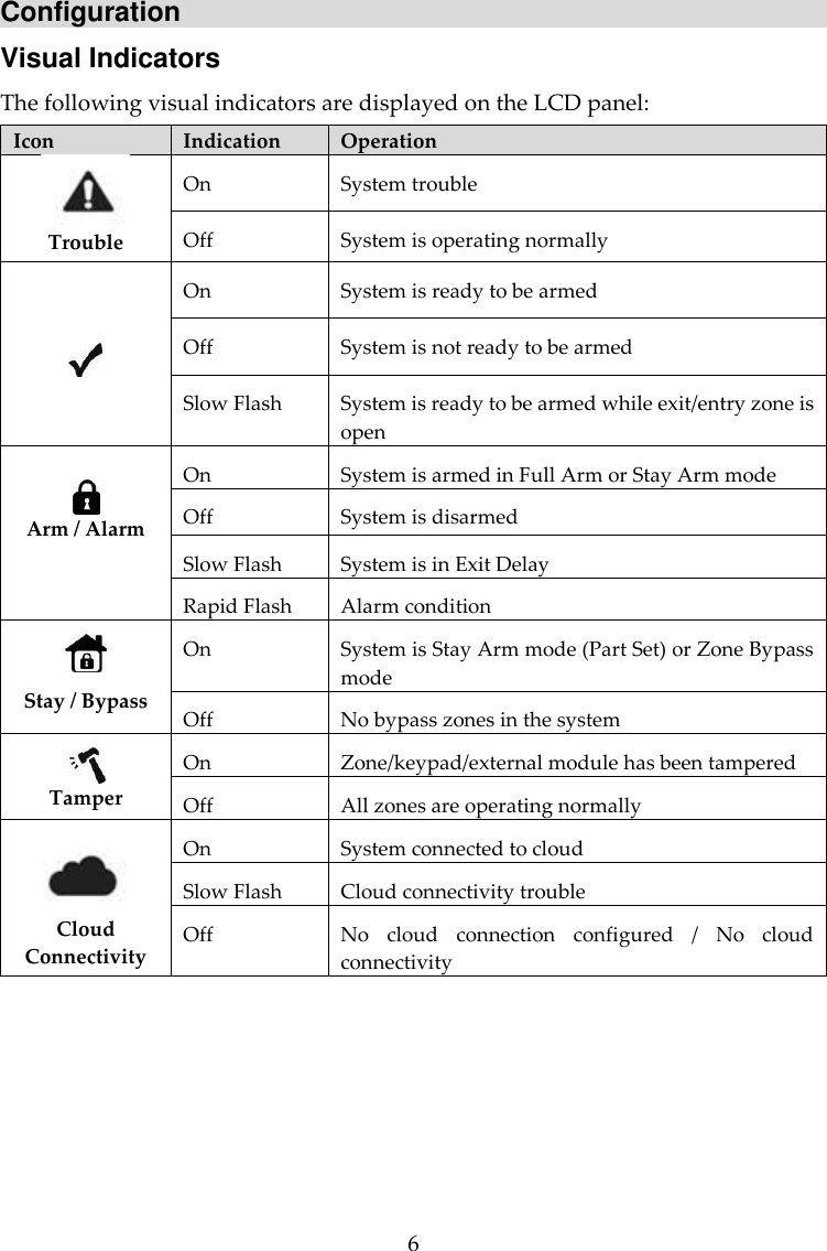
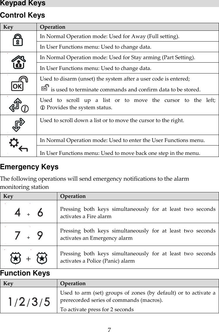
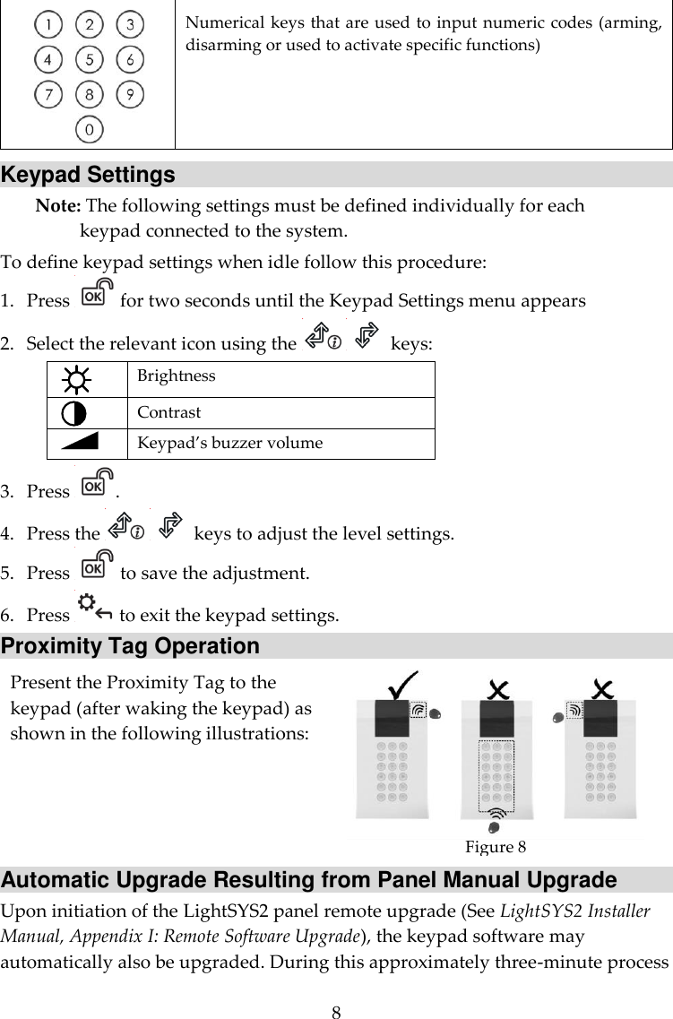
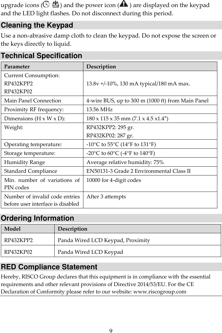
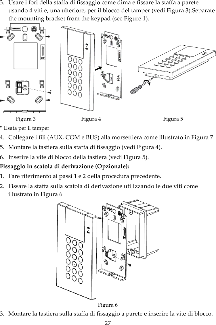
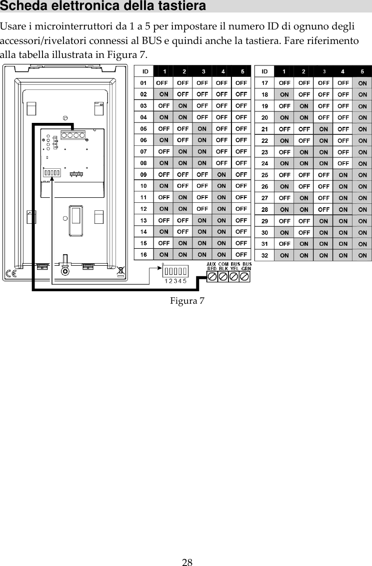
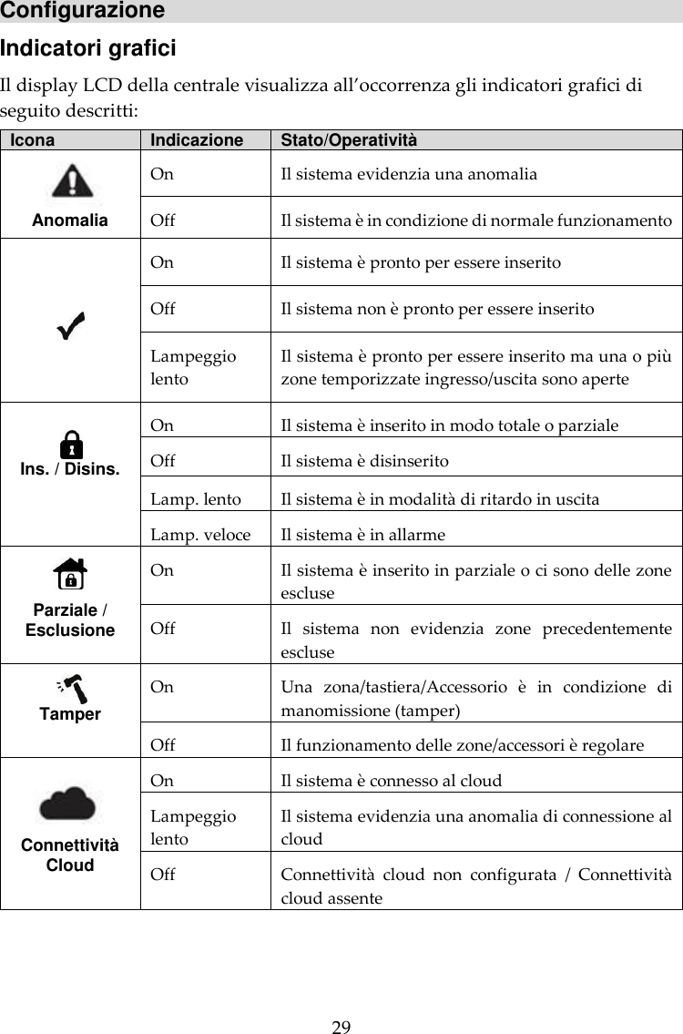
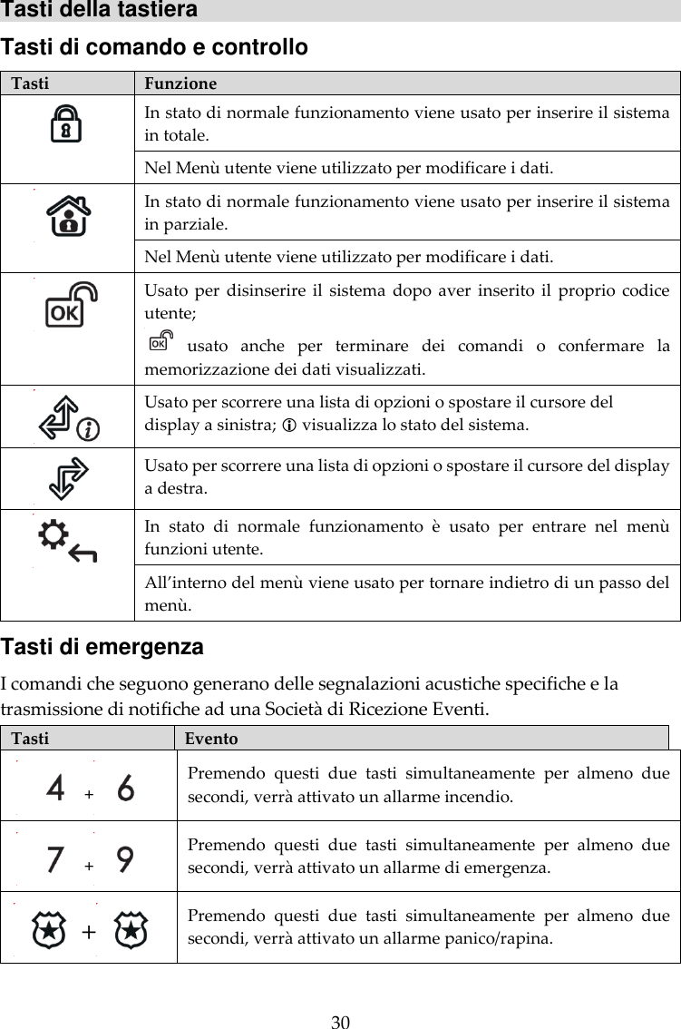
User Manual
Discussion / Help
Navigation