Risco RW132KPP1356 2W WL LCD Keypad, 915 User Manual 5IN2556 Agility Keypad 915
Risco Ltd. 2W WL LCD Keypad, 915 5IN2556 Agility Keypad 915
Risco >
User Manual

3
EN
Agility 2
Agility 2Agility 2
Agility 2-
--
-Way
Way Way
Way
Model: RW132KPPW3
Table of Contents
Table of ContentsTable of Contents
Table of Contents
INTRODUCTION ........................................................................................................... 4
MAIN FEATURES ......................................................
COMMUNICATION SETUP ........................................................................................ 4
MOUNTING THE KEYPAD ......................................................................................... 5
MAIN USER OPERATIONS ......................................................................................... 6
COMMON OPERATIONS ........................................................................................... 6
KEY OPERATION DURING PROGRAMMING MODE .......................................... 6
ADVANCED OPERATIONS .....................................
LEDS INDICATION ....................................................................................................... 7
SLEEP MODE................................................................................................................... 7
REPLACING BATTERIES ............................................................................................. 7
CHANGING KEYPAD PARAMETERS ....................................................................... 7
TECHNICAL SPECIFICATION .................................................................................... 8
2W WL LCD Keypad, 915

4
INTRODUCTION
INTRODUCTIONINTRODUCTION
INTRODUCTION
The 2-Way keypad is used to remotely program and operate the Agility security
system. Being bi-directional the 2-Way keypad receives a reply status indication from
the panel for each command that it has sent to the panel. To use functions of the
keypad you can use a code or a proximity tag.
COMMUNICATION SETUP
COMMUNICATION SETUPCOMMUNICATION SETUP
COMMUNICATION SETUP
The Keypad is automatically programmed to your control panel during the on-line
installation wizard setup. If you later purchase an extra keypad you can enroll it as
follows:
To quickly allocate a keypad at the control panel:
If the control panel is not already in Learn mode, press the button on the control
panel for 5 seconds; the unit beeps once as it enters Learn mode (all the LEDs also light
up, one after the other).
Make sure batteries are installed in each keypad before allocating them.
Send a signal transmission from the keypad by pressing and
simultaneously for at least 2 seconds; the control panel beeps once to accept or beeps
three times to reject. Once accepted, the system announces the device type and its zone
(for example, “Keypad, zone 1”).
When the keypads have been enrolled, short-press the control panel button to
exit Learn mode; the unit beeps once and the LEDs stop flashing.
Note:.
Note: For future use, it is recommended to write down the keypad description, zone number, and
installation location of each allocated keypad.

5
EN
MOUNTING THE KEYPAD
MOUNTING THE KEYPADMOUNTING THE KEYPAD
MOUNTING THE KEYPAD
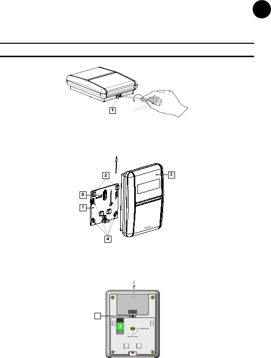
Mount the keypad on the wall using the supplied mounting bracket.
Note: Before mounting the keypad test the keypad communication with the system.
1. Release the Mounting bracket captive screw (1).
Figure 1
2. Slide up the Main Unit (3) to release it from the two mounting bracket's locking tabs
(2).
3. Mount the bracket.
Figure 2
4. Release the battery cover screw (1) and place the supplied 3 batteries.
5. Close the battery compartment and mount the keypad to the mounting bracket in a
reverse sequence to the removal.
1
Tamper
Figure 3

6
MAIN USER OPERATIONS
MAIN USER OPERATIONSMAIN USER OPERATIONS
MAIN USER OPERATIONS
The following list details the user operations from the 2-way wireless keypad. User
operation can be defined to be activated by a quick mode or high security mode that
requires the use of a code or proximity tag.
In the high security mode the proximity tag can be used as a substitute for inserting a
user code when the display prompts to "Insert a code".
COMMON OPE
COMMON OPECOMMON OPE
COMMON OPERATIONS
RATIONSRATIONS
RATIONS
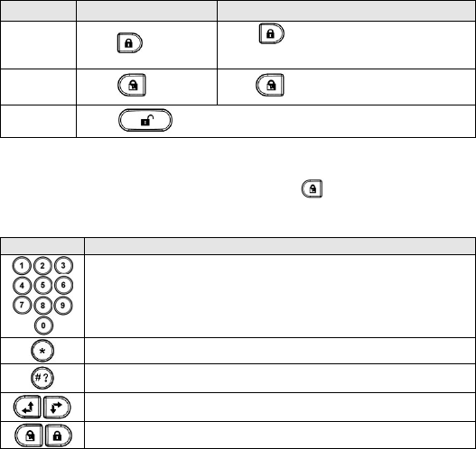
Operation Quick Operation High Security Mode
1
Full Set
(Away) Press Press followed by
code or proximity tag
2
Part Set
3
(Stay)
Press Press followed by code or proximity tag
Full Unset
(Disarm) Press followed by code or proximity tag
1. Consult your engineer for the operations defined with a code.
2. For optimal use of the proximity tag, use it from a distance of 1-2 cm from the center of the keypad's
door.
3. For Part Setting (Away Arming) with no entry delay press the key for two seconds.
KE
KEKE
KEY OP
Y OPY OP
Y OPERATION DURING PROGRAMMING MODE
ERATION DURING PROGRAMMING MODEERATION DURING PROGRAMMING MODE
ERATION DURING PROGRAMMING MODE
Key Description
Numerical keys are used to input the numeric codes that may be
required for setting, unsetting, or used to activate specific functions
Exits from the current menu and returns to Normal Operation mode
Terminates commands and confirms data to be stored
Used to browse through the menu: Scrolls up a list or moves the cursor
Changes data

7
EN
LEDS INDICATION
LEDS INDICATIONLEDS INDICATION
LEDS INDICATION
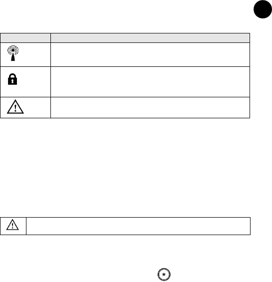
Key Function
(Blue)
Communication with the panel
(Red)
On: Fully or partially set
Slow flash: Exit delay
Rapid flash: Alarm
(Yellow)
Fault in the system while the system is unset.
SLEEP MODE
SLEEP MODESLEEP MODE
SLEEP MODE
For extending the battery life of the keypad, the keypad is designed with a Sleep mode
function. By default, 10 seconds after the last key has been pressed, the keypad will
turn off its display and LEDs. The time can be configured by your engineer to a
maximum of 60 seconds.
BATTER
BATTERBATTER
BATTERY
YY
Y
ACTIVATION
ACTIVATIONACTIVATION
ACTIVATION
Remove the batteries red strip to activate the batteries.
CAUTION: Risk of explosion if battery is replaced by an incorrect type. Dispose of
used batteries according to local regulations.
CHANGING KEYPAD PARAMETERS
CHANGING KEYPAD PARAMETERSCHANGING KEYPAD PARAMETERS
CHANGING KEYPAD PARAMETERS
Any change performed in the definition of the keypad parameters requires to update
the keypad as well. This is performed by pressing the key for 2 seconds. Doing so,
the panel will send an update to the keypad.

8
TECHNICAL SPECIFICATION
TECHNICAL SPECIFICATIONTECHNICAL SPECIFICATION
TECHNICAL SPECIFICATION
Electrical
Battery Type CR123, 3V lithium battery (x 3)
Current Consumption Stand by current 10µA,
Max current 100 mA
Frequency 13.56 MHz
Modulation Type OOK
Typical Battery Life 3 years
Physical
Dimension (HxWxD) 150 mm x 120 mm x 45 mm
(5.9 x 4.7 x 1.77 inches)
Weight (Including batteries) 0.395 kg
Environmental
Operating temperature -10°C to 40°C (14°F to 104°F)
Storage temperature -20°C to 70°C (-4°F to 158°F)
FCC ID: JE4RW132KPP1356
This device complies with part 15 of the FCC Rules. Operation is subject
to the following two conditions:
(1) This device may not cause harmful interference, and
(2) This device must accept any interference received, including interference that may
cause undesired operation.
Any Changes or modifications not expressly approved by the party responsible for
compliance could void the user's authority to operate the equipment
FCC Note
This equipment has been tested and found to comply with the limits for a Class B
digital device, pursuant to part 15 of the FCC Rules.
These limits are designed to provide reasonable protection against harmful interference
in a residential installation. This equipment generates uses and can radiate radio
frequency energy and, if not installed and used in accordance with the instructions,
may cause harmful interference to radio communications. However, there is no
guarantee that interference will not occur in a particular installation. If this equipment
does cause harmful interference to radio or television reception, which can be
determined by turning the equipment on and off, the user is encouraged to try to
correct the interference by one or more of the following measures:
• Reorient or relocate the receiving antenna.
• Increase the separation between the equipment and the receiver.
• Connect the equipment into an outlet on to a different circuit from that to
which the receiver is connected.
• Consult the dealer or an experienced radio/TV technician for help.

9
EN
STANDARD LIMITED PRODUCT WARRANTY
STANDARD LIMITED PRODUCT WARRANTYSTANDARD LIMITED PRODUCT WARRANTY
STANDARD LIMITED PRODUCT WARRANTY
RISCO Ltd., its subsidiaries and affiliates (“RISCO") guarantee RISCO’s hardware
products to be free from defects in materials and workmanship when used and stored
under normal conditions and in accordance with the instructions for use supplied by
RISCO, for a period of (i) 24 months from the date of connection to the RISCO Cloud (for
cloud connected products) or (ii) 24 months from production (for other products which
are non-cloud connected), as the case may be (each, the “Product Warranty Period”
respectively).
Contact with customers only. This Product Warranty is solely for the benefit of the
customer who purchased the product directly from RISCO, or from any authorized
distributor of RISCO. Nothing in this Warranty obligates RISCO to accept product returns
directly from end users that purchased the products for their own use from RISCO’s
customer or from any installer of RISCO, or otherwise provide warranty or other services
to any such end user. RISCO customer shall handle all interactions with its end users in
connection with the Warranty, inter alia regarding the Warranty. RISCO’s customer shall
make no warranties, representations, guarantees or statements to its customers or other
third parties that suggest that RISCO has any warranty or service obligation to, or any
contractual privy with, any recipient of a product.
Return Material Authorization. In the event that a material defect in a product shall be
discovered and reported during the Product Warranty Period, RISCO shall, at its
option, and at customer's expense, either: (i) accept return of the defective Product and
repair or have repaired the defective Product, or (ii) accept return of the defective
Product and provide a replacement product to the customer. The customer must
obtain a Return Material Authorization (“RMA”) number from RISCO prior to
returning any Product to RISCO. The returned product must be accompanied with a
detailed description of the defect discovered (“Defect Description”) and must
otherwise follow RISCO’s then-current RMA procedure in connection with any such
return. If RISCO determines in its reasonable discretion that any Product returned by
customer conforms to the applicable warranty (“Non-Defective Products”), RISCO will
notify the customer of such determination and will return the applicable Product to
customer at customer’s expense. In addition, RISCO may propose and assess customer
a charge for testing and examination of Non-Defective Products.
Entire Liability. The repair or replacement of products in accordance with this
warranty shall be RISCO’s entire liability and customer’s sole and exclusive remedy in
case a material defect in a product shall be discovered and reported as required herein.
RISCO’s obligation and the Warranty are contingent upon the full payment by
customer for such Product and upon a proven weekly testing and examination of the
product functionality.
Limitations. The Product Warranty is the only warranty made by RISCO with respect
to the Products. The warranty is not transferable to any third party. To the maximum
extent permitted by applicable law, the Product Warranty does not apply and will be
void if: (i) the conditions set forth above are not met (including, but not limited to, full
payment by customer for the product and a proven weekly testing and examination of
the product functionality); (ii) if the Products or any part or component thereof: (a)
have been subjected to improper operation or installation; (b) have been subject to

10
neglect, abuse, willful damage, abnormal working conditions, failure to follow RISCO’s
instructions (whether oral or in writing); (c) have been misused, altered, modified or
repaired without RISCO’s written approval or combined with, or installed on products,
or equipment of the customer or of any third party; (d) have been damaged by any
factor beyond RISCO’s reasonable control such as, but not limited to, power failure,
electric power surges, or unsuitable third party components and the interaction of
software therewith or (e) any delay or other failure in performance of the product
attributable to any means of communications, provided by any third party service
provider (including, but not limited to) GSM interruptions, lack of or internet outage
and/or telephony failure.
BATTERIES ARE EXPLICITLY EXCLUDED FROM THE WARRANTY AND RISCO
SHALL NOT BE HELD RESPONSIBLE OR LIABLE IN RELATION THERETO, AND
THE ONLY WARRANTY APPLICABLE THERETO, IF ANY, IS THE BATTERY
MANUFACTURER'S WARRANTY.
RISCO makes no other warranty, expressed or implied, and makes no warranty of
merchantability or of fitness for any particular purpose. For the sake of good order and
avoidance of any doubt:
DISCLAIMER. EXCEPT FOR THE WARRANTIES SET FORTH HEREIN, RISCO AND
ITS LICENSORS HEREBY DISCLAIM ALL EXPRESS, IMPLIED OR STATUTORY,
REPRESENTATIONS, WARRANTIES, GUARANTEES, AND CONDITIONS WITH
REGARD TO THE PRODUCTS, INCLUDING BUT NOT LIMITED TO ANY
REPRESENTATIONS, WARRANTIES, GUARANTEES, AND CONDITIONS OF
MERCHANTABILITY, FITNESS FOR A PARTICULAR PURPOSE, TITLE AND LOSS
OF DATA. WITHOUT LIMITING THE GENERALITY OF THE FOREGOING, RISCO
AND ITS LICENSORS DO NOT REPRESENT OR WARRANT THAT: (I) THE
OPERATION OR USE OF THE PRODUCT WILL BE TIMELY, SECURE,
UNINTERRUPTED OR ERROR-FREE; (ii) THAT ANY FILES, CONTENT OR
INFORMATION OF ANY KIND THAT MAY BE ACCESSED THROUGH THE
PRODUCT BY CUSTOMER OR END USER SHALL REMAIN SECURED OR NON
DAMAGED. CUSTOMER ACKNOWLEDGES THAT NEITHER RISCO NOR ITS
LICENSORS CONTROL THE TRANSFER OF DATA OVER COMMUNICATIONS
FACILITIES, INCLUDING THE INTERNET, GSM OR OTHER MEANS OF
COMMUNICATIONS AND THAT RISCO’S PRODUCTS, MAY BE SUBJECT TO
LIMITATIONS, DELAYS, AND OTHER PROBLEMS INHERENT IN THE USE OF
SUCH MEANS OF COMMUNICATIONS.
RISCO IS NOT RESPONSIBLE FOR ANY DELAYS, DELIVERY FAILURES, OR
OTHER DAMAGE RESULTING FROM SUCH PROBLEMS. RISCO WARRANTS
THAT ITS PRODUCTS DO NOT, TO THE BEST OF ITS KNOWLEDGE, INFRINGE

11
EN
UPON ANY PATENT, COPYRIGHT, TRADEMARK, TRADE SECRET OR OTHER
INTELLECTUAL PROPERTY RIGHT
IN ANY EVENT RISCO SHALL NOT BE LIABLE FOR ANY AMOUNTS
REPRESENTING LOST REVENUES OR PROFITS, PUNITIVE DAMAGES, OR FOR
ANY OTHER INDIRECT, SPECIAL, INCIDENTAL, OR CONSEQUENTIAL
DAMAGES, EVEN IF THEY WERE FORESEEABLE OR RISCO HAS BEEN
INFORMED OF THEIR POTENTIAL.
RISCO does not install or integrate the product in the end user security system and is
therefore not responsible for and cannot guarantee the performance of the end user
security system which uses the product.
RISCO does not guarantee that the product will prevent any personal injury or
property loss by burglary, robbery, fire or otherwise; or that the product will in all
cases provide adequate warning or protection.
Customer understands that a correctly installed and maintained alarm may only reduce
the risk of burglary, robbery or fire without warning, but is not an assurance or a
guarantee that such an event will not occur or that there will be no personal injury or
property loss as a result thereof. Consequently RISCO shall have no liability for any
personal injury, property damage or loss based on a claim that the product fails to give
warning.
No employee or representative of RISCO is authorized to change this warranty in any
way or grant any other warranty.
This RISCO product was purchased from:
No part of this document may be reproduced in any form without prior written
permission from the publisher.
© RISCO Group 07/2016. All rights reserved.
5IN2556