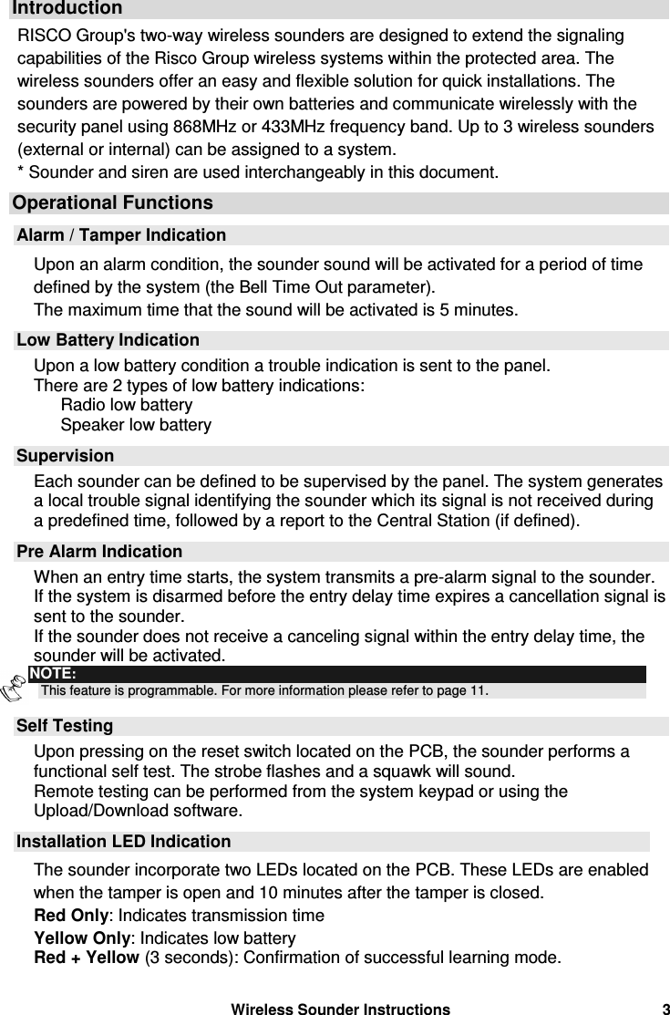
Risco RWRT433 Wireless Sounder User Manual 5INRWS50 C FCC
Risco Ltd. Wireless Sounder 5INRWS50 C FCC
UserManual.wiki
>
Risco
>
RWRT433 User Manual
Users Manual Revised
Navigation menu
Upload a User Manual
Namespaces
Wiki Guide
HTML
PDF
Info
Views
User Manual
Discussion / Help
Navigation
![2 Wireless Sounder Instructions Table Of Contents Introduction........................................................................................................... 3 Operational Functions.......................................................................................... 3 Alarm / Tamper Indication ...................................................................................3 Low Battery Indication.........................................................................................3 Supervision .........................................................................................................3 Pre Alarm Indication............................................................................................3 Self Testing .........................................................................................................3 Installation LED Indication...................................................................................3 Installation............................................................................................................. 4 Mounting the External Sounder...........................................................................4 Mounting the Internal Sounder............................................................................6 Programming Instructions ................................................................................... 7 Engineer Programming Menu .............................................................................7 [9][2][1] Siren: Allocation ............................................................................... 7 [9][2][2] Siren: Parameters ............................................................................ 8 [9][2][3] Siren: Communication Test .............................................................. 9 [9][2][4] Siren Receiver Calibration.............................................................. 10 [9][2][5] Siren: Tamper Mute........................................................................ 10 [1][1][9] Siren Supervision Time .................................................................. 10 [1][2][35] Siren Pre Alarm Feature............................................................... 11 [6][2][6][4] Siren Report Codes.................................................................... 11 Event Log Messages................................................................................... 12 User Programming Menu ..................................................................................13 Diagnostics.................................................................................................. 13 Siren Version............................................................................................... 13 Replacing Batteries ............................................................................................ 14 Technical Information......................................................................................... 14 Electrical ...........................................................................................................14 Radio.................................................................................................................14 Environmental ...................................................................................................14](https://usermanual.wiki/Risco/RWRT433/User-Guide-951502-Page-2.png)
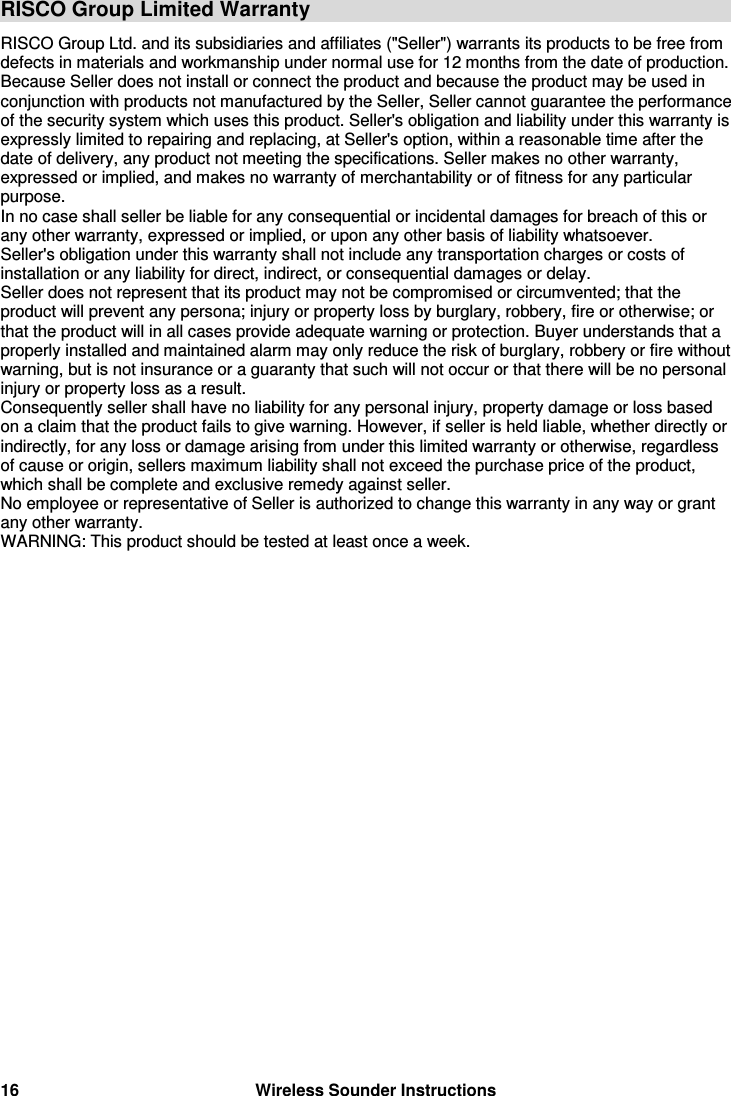
![Wireless Sounder Instructions 7 Programming Instructions The following section describes programming options added relating to the programming of the wireless sounder. Up to 3 wireless sounders (external or internal) can be assigned to the system. We recommend reading and fully understanding the system Installation and User manuals, before programming the sounder. Engineer Programming Menu To access the sounder menu 1. From the main engineer menu press [9] to access the More "Devices menu". 2. Press [2] for Siren. 3. You are now in the sounder submenus as described below. [9][2][1] Siren: Allocation The sounder must identify itself to the system's receiver by writing its ID into the System. Step 1: Introducing the Sounder to the System 1. After accessing the siren menu, press [1] for the Allocation menu 2. Select the sounder ID you want to assign. 3. Place the cursor over the Type filed. Use the key to choose one of the following options and then press [#] : NONE ODWS1: Outdoor wireless sounder INWS1: Indoor wireless sounder NOTE: After selecting the NONE option the system will ask you whether to erase the sounder or not. 4. Use the key to choose if the sounder will be audible [Y] or silent [N] and press [#]. 5. Use the key to choose if the squawk sound will be audible [Y] or silent [N] and press [#]. 6. Use the key to choose if the squawk strobe is enabled [Y] or disabled [N] and press [#]. NOTE: The definition of the squawk strobe is applicable only for the outdoor (ODWS1) sounder.](https://usermanual.wiki/Risco/RWRT433/User-Guide-951502-Page-7.png)
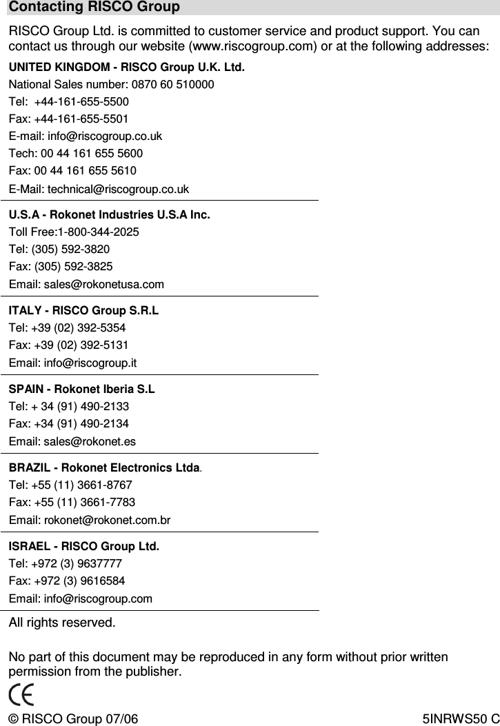
![8 Wireless Sounder Instructions Step 2: Setting communication with the system 1. After adding the sounder to the panel, the sounder must identify itself to the system's receiver by writing its ID into the system's receiver. Select the appropriate option as follows: Press [1] to Skip to the next sounder assignment Press [2] to allocate the sounder into the system. Send a write signal (within 255 seconds) from the sounder as follows: a. Press the reset switch on the sounder. b. After a squawk is sounded and the sounder's strobe flashes (only in outdoor sounder) you have 10 seconds to press on the tamper switch for at least 3 seconds. If the sounder is successfully recognized, the system will sound a confirmation beep, the sounder will initiate a squawk sound and the 2 LEDs on the sounder will flash for 3 seconds. Press [3] to erase the sounder from the system memory. Press [4] to select whether the sounder will be supervised or not. 2. Repeat the process for other sounders in the system (up to 3). [9][2][2] Siren: Parameters Using this menu you can define parameters that reflect the operation of the sounder. To set the sounder parameters 1. From the engineer menu, access the siren parameters submenu, Quick Key [9][2][2]. 2. Enter the number of the sounder that you want to program and then press [#]. You can now program the sounder parameters. NOTE: For internal sounder (INWS1) only the Volume parameter is available. Siren: Parameters Quick Keys Parameter [9][2][2][1] Strobe Control Defines the Strobe operation mode. [9][2][2][1] [1] Always Off The strobe is deactivated [9][2][2][1] [2] Follow Bell (Default) The strobe is activated when the sounder bell is triggered. [9][2][2][1] [3] Follow Alarm The strobe is activated when an alarm event occurs in the system.](https://usermanual.wiki/Risco/RWRT433/User-Guide-951502-Page-8.png)
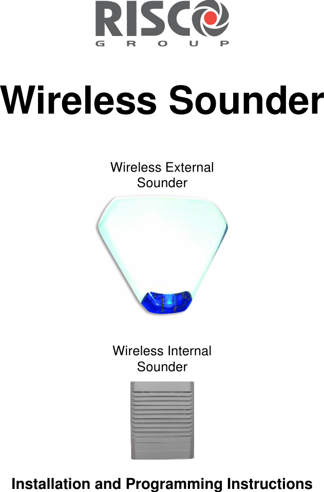
![Wireless Sounder Instructions 9 [9][2][2][2] Strobe Blink Defines the number of times that the strobe will flash per minute. [9][2][2][2] [1]..[5] Strobe Blink options [1] 20 times per minute [2] 30 times per minute [3] 40 times per minute (Default) [4] 50 times per minute [5] 60 times per minute [9][2][2][3] Strobe Arm Squawk Default: 05 Range: 01-20 (seconds) The time that strobe blinking will continue when arm is performed. NOTE: If the sounder’s squawk strobe is defined as NO (Refer to Allocation section) this parameter will be ignored. [9][2][2][4] Volume Defines the sounder sound volume for the following system modes. The sound volume range is between 0 (silent) to 5 (maximum volume). [9][2][2][4] [1] Exit / Entry The sound produced during exit/entry time Default: 0 [9][2][2][4] [2] Alarm The sound produced during alarm. (Default: 9) [9][2][2][4] [3] Squawk The sound produced during squawk sounds (Default: 9) [9][2][3] Siren: Communication Test The sounder communication test performs a communication test between the sounder receiver and the system. The value displayed indicates the receiving level of the signal sent from the system to the sounder's receiver. To perform communication test 1. From the engineer menu access the siren communication test submenu, Quick Key [9][2][3]. 2. The system sends a test signal to the sounders. A number between 00-99 indicates the strength of the communication signal between the system and the sounder. NOTE: For successful communication, the strength of the signal should be higher that the sounder receiver noise threshold level (see quick key [9][2][4]) .](https://usermanual.wiki/Risco/RWRT433/User-Guide-951502-Page-9.png)
![10 Wireless Sounder Instructions [9][2][4] Siren Receiver Calibration This feature establishes the threshold noise level of the wireless sounder receiver for successful communication with the system. To calibrate the sounder receiver 1. From the engineer menu access the siren receiver calibration submenu, Quick Key [9][2][4]. 2. Select the sounder for which you want to calibrate its receiver. 3. To perform a new automatic calibration, use the key to select [Y]. After the calibration process is accomplished, the new noise threshold level is displayed. 4. To confirm the new threshold level, press [#] or change the threshold level manually and then press [#]. [9][2][5] Siren: Tamper Mute Selecting this option will disable the tamper sound during the current installation programming period. NOTE: An ongoing tamper alarm will not be disabled. [1][1][9] Siren Supervision Time System: Timers Quick Keys Parameter Default Range [1][1][9] Accessory Supervision Time 60 minutes 00-255 minutes Specifies the siren supervision time parameter, i.e. if set to 60 minutes the siren will send a supervision signal every 60 minutes. If any of the sounders does not transmit to the panel at least once, during the supervision time of the system receiver (Quick Key [1][3][3] ) the system will regard the sounder as Lost. IMPORTANT: The supervision time of the system receiver (Quick key [1][3][3]) should be higher than the accessory supervision time ([1][1][9]) in order to eliminate false lost event.](https://usermanual.wiki/Risco/RWRT433/User-Guide-951502-Page-10.png)
![Wireless Sounder Instructions 11 [1][2][35] Siren Pre Alarm Feature This wireless sounder incorporates a pre alarm feature that enhances the security of the system, by producing a local alarm in case of the sabotage. NOTE: In the UK version of the system the quick key of this parameter is [1][2][44]. System: Control Quick Keys Parameter Default [1][2][35] Siren Pre Alarm No Specifies if the system will send a Pre Alarm message to the sounder while an entry delay starts. Yes: The system sends a pre alarm signal to the sounder at the beginning of the entry delay. If the sounder does not receive a cancellation signal from the system at the end of the entry time, the sounder goes into alarm. No: Pre Alarm disabled [6][2][6][4] Siren Report Codes The following are the new report codes related to the wireless sounders. Report codes Manual Wireless Siren Quick Keys Parameter [6][2][6][4] [1] Tamper Tamper alarm from sounder X [6][2][6][4] [2] Tamper Restore Tamper alarm restore from sounder X [6][2][6][4] [3] Battery Trouble Report code for a low battery condition in a wireless sounder [6][2][6][4] [4] Battery Trouble Restore Report code for the correction of a low battery condition [6][2][6][4] [5] Lost Trouble A report code that indicates the following condition: If any of the sounders does not respond to any request from the system, during the supervision time of the system receiver (Quick Key [1][3][3] ), the system will regard the sounder as Lost. [6][2][6][4] [6] Lost Trouble Restore Restore is established when the system receives any signal from the sounder.](https://usermanual.wiki/Risco/RWRT433/User-Guide-951502-Page-11.png)
![Wireless Sounder Instructions 13 User Programming Menu Diagnostics The diagnostics menu enables to test parameters that reflect the operation of the sounder. To perform diagnostics: 1. From the user menu press [] [4] to access the Maintenance menu. 2. Enter the Engineer code (or sub-engineer) and press [#]. 3. Press [7][1] to access the Siren diagnostic menu. 4. Enter the digit representing the sounder you want to test and then press [#]. The system will perform the diagnostics test and a list of test parameters will appear, as indicated in the table below. 5. Use the arrow keys to view the diagnostics test results. NOTE: The diagnostic features can be also performed from Upload/Download software, locally or remotely. Maintenance: Siren Diagnostics Quick Keys Parameter [4][7][1] Siren Diagnostics Speaker batteries voltage: Tests the selected sounder’s speaker batteries voltage. Radio (Transceiver) batteries voltage: Tests the selected sounder’s radio's batteries voltage. Siren Version This menu displays information regarding the sounder's version. Repeat steps 1 to 4 in the Siren diagnostic section with the exception of pressing [7][2] in step 3 for the Siren version option. Maintenance: Siren Version [4][7][2] Siren Version Sounder part number: F=Frequency (868MHz / 433MHz) V=Siren type (Internal/External), C= lens Color Sounder software version Sounder software date Sounder software checksum](https://usermanual.wiki/Risco/RWRT433/User-Guide-951502-Page-13.png)
![14 Wireless Sounder Instructions Replacing Batteries 1. To silence the tamper alarm enter the engineer programming mode, quick key [9][2][5] and activate the Tamper Mute option. 2. Remove the sounder cover as described in the installation section. NOTE: If required you can silence a tamper alarm by pressing the RESET Switch. 3. Remove the old batteries from the metal clips and replace with new ones. Pay attention to the polarity. 4. Press the RESET switch. 5. Close the cover and fasten the cover locking screw. NOTE: Dispose of batteries according to your local regulations Technical Information Electrical Power Supply 5 X CR123, 3V Lithium Battery (3 batteries for the Radio Transceiver, 2 batteries for the Speaker/Strobe, see External and Internal Sounder - PCB Diagrams on pages 5 and 6) Battery life 3 years (typical) Speaker sound level 105 dB @ 1 meters (adjustable) Strobe lens (External sounder) Polycarbonate, available in amber, red, blue or transparent Strobe flash rate (External sounder) 60 times per minute (maximum) Size: External sounder (HxWxD) 300x 325x70 mm (11.8 x12.8x2.8 inch) Size: Internal sounder (HxWxD) 145 x 120 x 50 mm (5.7x4.7x2 inch) External sounder Weight (batteries included) 1 Kg (35.2 oz) Internal sounder Weight (batteries included) 0.44Kg (15.52 oz) Radio Radio type Two Way Narrow band Frequency 868 MHz or 433MHz Range up to: 150m (492’) Line of sight Supervision Yes Modulation Type ASK Environmental Temperature -25°C to 60°C (-4°F to 140°F) IP Rating IP 44 Environmental Class Class IV](https://usermanual.wiki/Risco/RWRT433/User-Guide-951502-Page-14.png)