Risco RWT6G915 WL GLASSBREAK DETECTOR 915MHZ User Manual
Risco Ltd. WL GLASSBREAK DETECTOR 915MHZ
Risco >
User Manual
Model: RWT6G
Installation instructions
1 General Description
The Wireless VITRON is an advanced microprocessor based
Acoustic Glass Break detector. The Wireless VITRON detects the
breaking of most common types of framed glass panes while
ignoring false alarms.
2 Installation Procedure
Note: To improve detection, It is highly recommended to use a
swivel adaptor, especially for ceiling and wall installations.
Fig 1
:
Percentage of Maximum
Range as a function of angle
between Wireless VITRON and
glass.
Verify that the distance between the Wireless VITRON and the
furthest point on the protected glass does not exceed the maximum
specified range taking into account the reduced range due to angle
(see Fig 2).
Fig 2:
Angle between Wireless
VITRON and glass
Other factors affecting range:
•
There should be no obstructions between the Wireless VITRON
and the protected glass.
•
Curtains and blinds may reduce the effective range.
•
Sound absorbing materials in the protected area may reduce the
range.
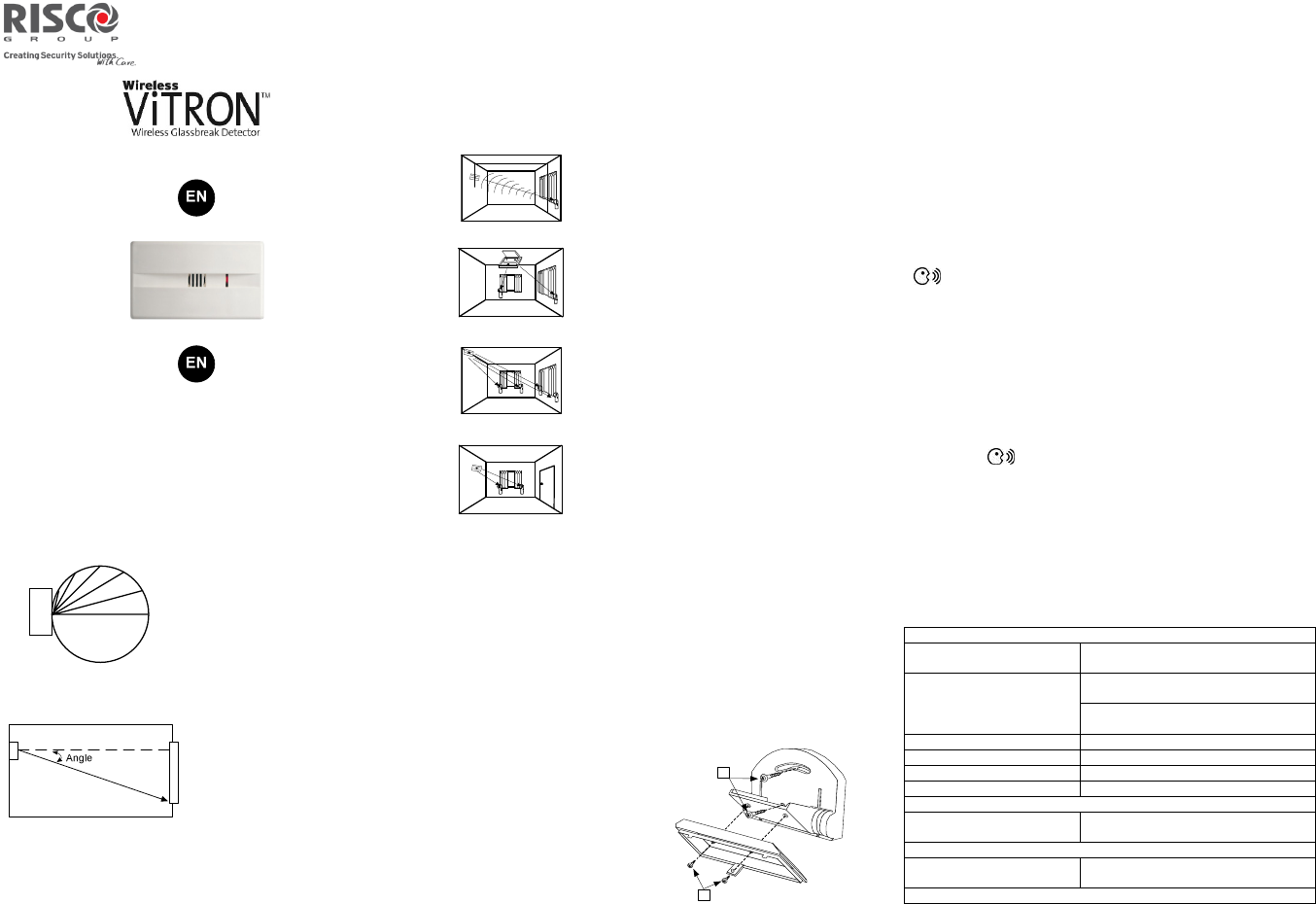
3 Mounting Location
For optimal performance the Wireless VITRON should be mounted as
nearly opposite to the glass area to be protected, as shown in Fig 3.
Attach the Glassbreak detector to the surface using the adhesive strips.
Fig. 3
•
Opposite Wall
–
Mounted
(For optimal
results, Wireless VITRON is centered
opposite glass, see Fig. 3).
Fig. 4
•
Ceiling Mounted
(for optimal results
Wireless VITRON is centered and directed
towards protected glass, using the supplied
swivel adaptor, see fig. 4)
Fig. 5
•
Corner Mounted
(choose corner opposite
glass to be protected see fig. 5)
Fig. 6
•
Side wall
–
mounted
not recommended
due to the fact that the Wireless VITRON is
not opposite the glass - see range versus
angle diagram (Fig 2).
Notes:
Do not mount Wireless VITRON on same wall as the protected glass.
Avoid installing the Wireless VITRON near sources of loud noise or
vibrations (air conditioners, fans, compressors, stereos, etc).
Avoid defining the Wireless VITRON as a 24 hour zone
The Wireless VITRON should always be installed in addition to
standard motion detectors
4 Mounting
Use the two-sided adhesive tape to attach the detector to the surface.
5 Swivel Mounting
When installing the Wireless
VITRON with the supplied swivel
mounting adaptor, maximum
installation flexibility and
performance is achieved.
To install the swivel mounting
adaptor perform the following:
1. Remove the PCB from the
Wireless VITRON back plate
2. Open the swivel mounting
adaptor knockouts (4, Fig 7).
3. Attach the swivel mounting
adaptor to the back plate using
the two supplied screws (1, Fig
Fig. 8
8).
4. Mount the Wireless VITRON on the required location (wall or
ceiling) using the supplied screws (2, Fig 8). Do not tighten the
screws.
5. Adjust the detector so it will face the protected glass.
6. Tighten the bolts to the final torque.
6 Quick Device Allocation at the Control Panel
The Glassbreak detector is automatically programmed to your control
panel during the on-line installation wizard setup. If you later
purchase an extra detector you can enroll it as follows:
To quickly allocate the detector at the control panel:
If the control panel is not already in Learn mode, press the
button on the control panel for 5 seconds; the unit beeps once
as it enters Learn mode (all the LEDs also light up, one after the
other).
Remove the plastic wrapping from the batteries before installation
and make sure the cover is removed so the internal tamper switch is
accessible.
Send a signal transmission from the detector by pressing the tamper
button for at least 2 seconds; the control panel beeps once to accept
or beeps three times to reject. Once accepted, the system
announces the device type and its zone (for example, “Detector,
zone 1”).
When the detectors have been enrolled, short-press the control
panel button to exit Learn mode; the unit beeps once and the
LEDs stop flashing.
Note: For future use, it is recommended to write down the detector
description, zone number, and installation location of each allocated
detector.
7 Jumpers settings
Please do not change the jumper settings.
8 Technical Specifications
Electrical
Current
consumption
(standby)
22 uA at 3 VDC, without acoustic
signal
Current consumption
(Alarm transmission)
10 mA at 3 VDC
(Max. with LED OFF)
15 mA at 3 VDC
(Max. with LED ON)
Battery life
3 years, at 65 minutes supervision
Range (loss) 300m (1000 feet)
Voltage requirements CR123A 3VDC Lithium Batteries
Frequency 915MHz
Physical
Size
(LxWxD)
87 x 50.7 x 28.6 mm
(3.4 x 2.0 x 1.1 in.)
Environmental
Operating/Storage
temperature
0°C to 50°C (
-
32°F to 122°F)
* Specifications are subject to change without prior notice
Note: The detector contains a swivel.
75°
60°
45°
30°
15°
0°
WIRELESS
VITRON
VITRON
VITRON
VITRON
VITRON VITRON
VITRON
VITRON
VITRON VITRON
2
1

RISCO Group Limited Warranty
RISCO Group and its subsidiaries and affiliates ("Seller") warrants its products to be free from
defects in materials and workmanship under normal use for 24 months from the date of
production. Because Seller does not install or connect the product and because the product may
be used in conjunction with products not manufactured by the Seller, Seller can not guarantee
the performance of the security system which uses this product. Sellers' obligation and liability
under this warranty is expressly limited to repairing and replacing, at Sellers option, within a
reasonable time after the date of delivery, any product not meeting the specifications. Seller
makes no other warranty, expressed or implied, and makes no warranty of merchantability or of
fitness for any particular purpose. In no case shall seller be liable for any consequential or
incidental damages for breach of this or any other warranty, expressed or implied, or upon any
other basis of liability whatsoever. Sellers obligation under this warranty shall not include any
transportation charges or costs of installation or any liability for direct, indirect, or not be
compromised or circumvented; that the product will prevent any persona; injury or property loss
by intruder, robbery, fire or otherwise; or that the product will in all cases provide adequate
warning or protection. Buyer understands that a properly installed and maintained alarm may
only reduce the risk of intruder, robbery or fire without warning, but is not insurance or a guaranty
that such will not occur or that there will be no personal injury or property loss as a result.
Consequently seller shall have no liability for any personal injury, property damage or loss based
on a claim that the product fails to give warning. However, if seller is held liable, whether directly
or indirectly, for any loss or damage arising from under this limited warranty or otherwise,
regardless of cause or origin, sellers maximum liability shall not exceed the purchase price of the
product, which shall be complete and exclusive remedy against seller. No employee or
representative of Seller is authorized to change this warranty in any way or grant any other
warranty.
WARNING: This product should be tested at least once a week.
CAUTION: Risk of explosion if battery is replaced by an incorrect type. Dispose of used batteries
according to local regulations.
FCC ID: JE4RWT6G915
This device complies with part 15 of the FCC Rules. Operation is subject
to the following two conditions:
(1) This device may not cause harmful interference, and
(2) This device must accept any interference received, including interference that
may cause undesired operation
Changes or modifications to this equipment which are not expressly approved by
the party responsible for compliance (RISCO Group's.) could void the user's
authority to operate the equipment.
FCC Note
This equipment has been tested and found to comply with the limits for a
Class B digital device, pursuant to part 15 of the FCC Rules.
These limits are designed to provide reasonable protection against harmful
interference in a residential installation. This equipment generates uses and
can radiate radio frequency energy and, if not installed and used in
accordance with the instructions, may cause harmful interference to radio
communications. However, there is no guarantee that interference will not
occur in a particular installation. If this equipment does cause harmful
interference to radio or television reception, which can be determined by
turning the equipment on and off, the user is encouraged to try to correct the
interference by one or more of the following measures:
Reorient or relocate the receiving antenna.
Increase the separation between the equipment and the receiver.
Connect the equipment into an outlet on to a different circuit from that to
which the receiver is connected.
Consult the dealer or an experienced radio/TV technician for help.
© RISCO Group 07/16 5IN2582