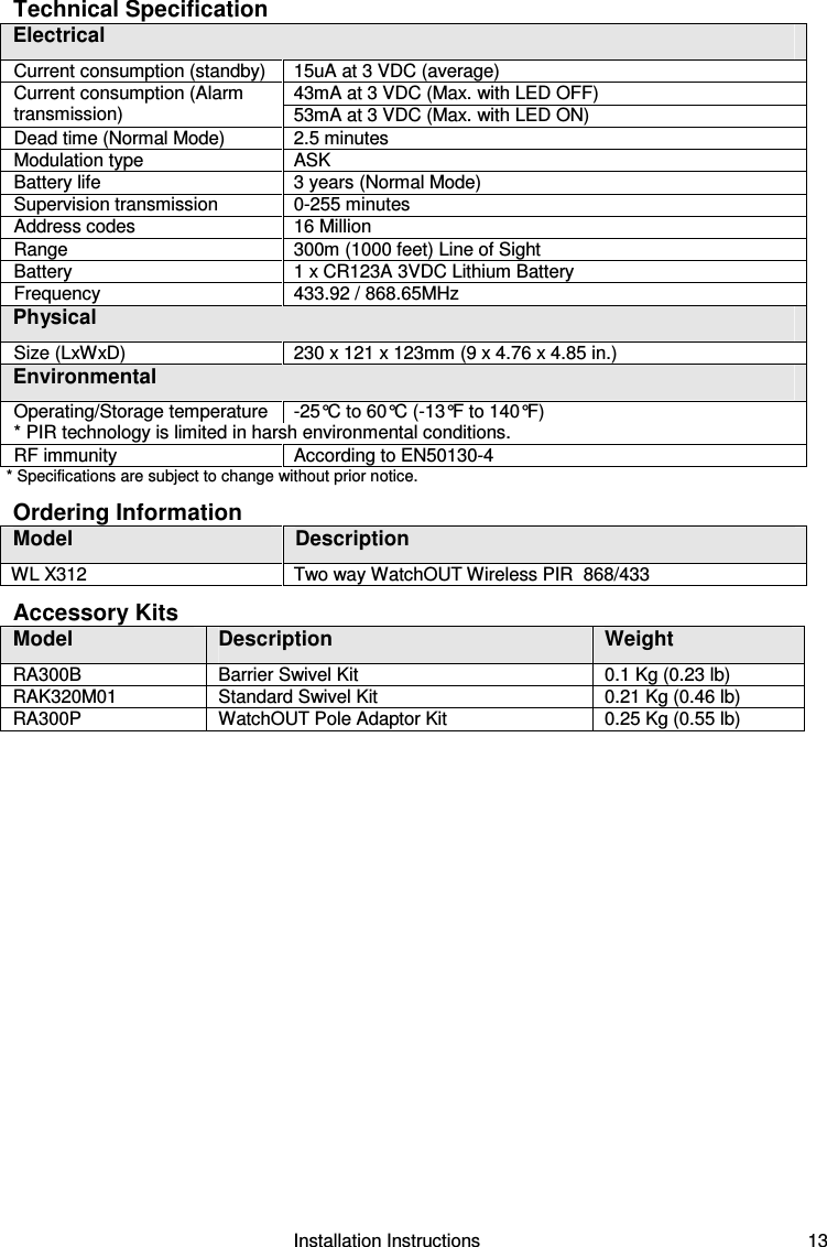
Risco RWX312PR4 TWO WAY WIRELESS PIR OUTDOOR DETECTOR User Manual 5IN1412 w correct FCC ID

Risco Ltd. TWO WAY WIRELESS PIR OUTDOOR DETECTOR 5IN1412 w correct FCC ID

Users Manual

   Two Way Wireless PIR Outdoor Detector    WL X312  Installation Instructions
2   Installation Instructions
                                                       Installation Instructions   3 Table of Contents  Installation ..............................................................................................................................4 Introduction ............................................................................................................................4 Mounting.................................................................................................................................4 Mounting Considerations......................................................................................................4 Wall Mount Installation .........................................................................................................6 Flat Mounting .......................................................................................................................6 45° angle Mounting (Left side mounting) ..............................................................................6 Changing Back Tamper position ..........................................................................................7 Back Tamper Terminal Wiring ...............................................................................................7 Configuration Parameters......................................................................................................7 Detection Length Adjustment................................................................................................8 Walk test .................................................................................................................................9 LEDs Display ..........................................................................................................................9 Operational Modes .................................................................................................................9 Transmitter/Receiver Communication link setup.................................................................9 Standard Swivel Installation (Optional)...............................................................................10 Wall Mounting ....................................................................................................................10 Replacing Lenses.................................................................................................................12 Technical Specification........................................................................................................13 Ordering Information............................................................................................................13 Accessory Kits .....................................................................................................................13
4   Installation Instructions Installation Introduction RISCO Group's WL X312 is a unique detector with signal processing based on two Passive Infrared (PIR) channels. The WL X312 has an adjustable detection range. The detector is compatible with all RISCO Group Wireless and Hybrid systems. The following instructions describe the installation of the WL X312.  Mounting Mounting Considerations 1. Installation Height: 0.8m - 1.2m                                    (2'8" – 3'11")     Typical Installation Height: 1m (3'3")  2. To ensure maximum operational reliability, install the detector perpendicular to the ground so that the upper detection area is parallel to the ground.     3. For optimum detection, select a location that is likely to intercept an intruder moving across the coverage pattern.    4. Avoid pointing the detector to moving objects (swaying trees, bushes etc.)  Out ofDetection RangeWith moving objectskeep distance ofminimum 5 meters (16')5m (16') 5. Ensure any objects do not obstruct the field of view. Pay attention to growing trees or bushes, plants with big moving leaves etc.
                                                       Installation Instructions   5 Installing the WL X312 detector in challenging situations In the following situations, rapid and significant infrared radiation changes can happen in both PIR channels together, resulting in false alarms and therefore care should be taken.  1.  Situations in which metal and/or glass objects measuring over 70cm (2’4”) in height from the ground are in the field of view of the detector (cars, metal gates, shutters, metal walls, windows, etc.)  2.  Situations in which a reflective surface on the ground larger than 1m (3’4”) in diameter may cause reflection into the detector’s lens. Examples of a reflective surface on the ground are a puddle, wet road or car park, smooth concrete or asphalt surface, swimming pool, etc.  Water Reflection  NOTES: 1.  Please note that any outdoor PIR detector will require reduction in range to a shorter distance than the car, metal object or surface reflection (so that these objects won’t be protected) in order to eliminate false alarms. 2.  For full 15m (50’) coverage in the above situations, it is highly recommended to install the wired WatchOUT DT, the only outdoor detector with 2 PIR channels and 2 Microwave channels. 3.  Wireless WatchOUT detectors include high quality Silicon filters on the PIR sensors for blocking out white light interferences. These filters are not intended to block infrared thermal radiation.
6   Installation Instructions Wall Mount Installation Figure 1 C1 Figure 2 I1Figure 3 TamperLeverAT5T1B2W9B3W2BL1T3B1L2W3B4R1R2(not visible)T2T6(not visible)T4W5W6 NOTE: The installation knockouts numbering  are marked on the back plate. 1.  Open the WL 312 front cover (unlock C1, Figure 1). 2.  Release internal base (unlock I1, Figure 2). 3.  Select mounting installation as follows: Flat Mounting: Open knockouts on external base (Figure 3). •  B1 - B4: Wall mounting knockouts •  T1: Back tamper knockout 45° angle Mounting (Left side mounting): a.  Open knockouts on external base  (Figure  3). •  L1, L2: Left mounting knockouts  •  T3: Left tamper knockout b.  Remove tamper spring (Figure 4). c.  Replace tamper bracket (Item 1) with supplied flat tamper bracket (Item 2).   Item 1  Item 2  d.  Insert Tamper lever B onto T6 and T3 and secure screw A (Figure 3). 4.  Secure external base to the wall. 5.  Insert tamper wires through internal base (Figure 4). 6.  Secure internal base to external base (lock I1, Figure 2). 7.  Close the front cover (Lock C1, Figure 1) after wiring and setting DIP switches. 8.  Walk test the detector. Figure 4   NOTE: For 45° right side installation use the equivalent units on the external base as follows: Knockouts Description Left Right Mounting Knockouts  L1, L2  R1, R2 Tamper spring knockouts  T1,T3  T2,T4 Tamper  screw anchor   T5  T6
                                                       Installation Instructions   7 Changing Back Tamper position: The back tamper is by default secured on the right side of the internal base (Rear view). If you wish to move it to the left side (rear view), do the following (Figure  5): 1.  Remove tamper screw 1 in order to release the tamper from position 7. 2.  Ensure tamper spring (2) rests over tamper wire base 4. 3.  Ensure plastic tamper bracket (3) rests over both 2 and 4. 4.  Secure tamper screw (1) into (3) over position 6. Figure 5  Left Side TamperRight    Side Tamper3612475  NOTES:   1.    Verify that you hear a "Click" when attaching the tamper spring to the wall. 2.    For pole installation, the tamper can be moved to the bottom right-hand side of the internal base. Back Tamper Terminal Wiring If you wish to use the back tamper (recommended) remove the short from the back tamper terminal block and connect the back tamper wires to the back tamper terminal block. Back Tamper in useBACK TAMPERBack Tamper not usedShortH1 H1 Configuration Parameters Via the panel you can define the following parameter settings of your detector according to your needs:  1. LEDs operation     On: LEDs enabled (Default: On)     Off: LEDs disabled 2. PIR Sensitivity: High/Normal/Mid/Low (Default: Normal) 3. Mode: Normal/Walk Test (Default: Normal) For more information refer to the Agility Installer Guide.
8   Installation Instructions Detection Range Adjustment   Slide the moving PIR to the desired position, see figure 6.   The range of the lower detection area determines the detection range. The upper PIR is fixed and its detection area is parallel to the ground at all times. The lower detection area changes from 2m to 12m depending on the location of the moving PIR. Therefore, the detection range is established according to the location of the lower PIR since both the upper and the lower PIR should be triggered in order to activate an alarm.    Figure 6    Detection patterns (side view):       Detection range with 1m (3'3") installation height:  * NOTE: Length may vary according to environmental thermal conditions.
                                                       Installation Instructions   9 Walk test Two minutes after applying power, walk test the protected area to verify proper operation. Adjust the moving PIR for required detection range and reliability. NOTE:  When  there  is  traffic  in  the  detection  area  the  detection  area  may  increase  due  to  environmental  thermal conditions, therefore it is recommended to increase the detection area from 1.5m to 2m away from the traffic.  IMPORTANT! Both upper and lower detection areas must be blocked simultaneously for detection to occur, see figure 7 below.  Figure 7 LEDs Display LED  State  Description RED   Steady   Indicates ALARM  Operational Modes Operational Mode  Description Normal   Dead time (between detection alarms) is 2.5 Minutes. Test (walk test)   Dead time (between detection alarms) is 2.5 sec. Write (for enrolling)   The unit transmits a WRITE message each time both of the Tamper    Switches (back and cover) are closed for at least 3 seconds.   NOTE:   After power up the detector enters into test mode for a period of 20 minutes (disregarding the DIP Switch Modes Position). Transmitter/Receiver Communication link setup The detector must identify itself to the system’s receiver by writing its coded message into the receiver’s address memory. This is accomplished by performing the following steps: 1. Set the receiver to Write Mode. 2. Remove the insulation material from the batteries and place them in the batteris holders on the PCB on the right direction (pay attention to the "+" and "–" diagram on the PCB) 3. Send a WRITE message by pressing both of the tamper switches (back and cover) for at least 3 seconds.  4. Verify that the detector has been identified by the receiver.
10   Installation Instructions CAUTION NOTICE Changes or modifications not expressly approved by RISCO Group may void the user’s authority to operate this equipment. Simultaneous transmissions from two different units may cause message interference resulting in loss of information. The communication quality of this unit may be affected by its surrounding environment. Nearby electrical equipment may interfere with its normal operation. The operation of this unit must, therefore, be tested at each installation since its transmission quality may vary as a result of operational conditions. NOTE: DIP Switch 1 should be in ON position to enable LED indications (regardless during the first 20 minutes after power up). Swivel Installation (Not Supplied) Please follow the instructions below for mounting the detector with the Swivel: 1.  Open WL X312 front cover (Unlock C1, Figure 1). 2.  Release internal base (Unlock I1, Figure 2). 3.  Remove back tamper from the internal base (see the “Changing Back Tamper Position" paragraph on page 7) and connect it to S5 (Figure 8, Detail A) on the Standard Swivel. 4.  Select the mounting installation as follows: NOTE:  Ensure that you see the engraved UP mark on the upper front face of the swivel. Wall Mounting 1.  Insert back tamper wires through the Swivel Wires Passage (Figure 8, Detail B). 2.  Secure swivel to the wall through holes S1, S3, S6 and S8.   Detail BS1W1S2S3SnapsDetail CS1 S2S8S6S5S4Tamper (see Detail C)Detail AStandard Swivel Figure 8 3.  Connect the external base to the swivel using the dedicated snaps (Figure 9).
                                                       Installation Instructions   11  Figure 9 NOTE: Do not open or close the Swivel Assy Screw since it is used for connecting the swivel parts only (factory tightened). 4.  Secure external base to swivel with two screws fastened trough knockouts S1 and S2  (Figure 9). 5.  Insert the supplied angle locking screw from the external base through the angle locking screw knockout S3 on the external base to the standard swivel (Figure 9). 6.  Rotate the Standard Swivel to the desired position. Once the Standard Swivel is in the desired position, secure the angle locking screw. IMPORTANT! Take care not to tilt the detector upwards and downwards. The detector should remain perpendicular to the ground for maximum detection and reliability. 7.  Line up the internal base onto the external base. Insert tamper wiring through the internal base.  8.  Secure internal base to external base (Lock I1, Figure 2). 9.  To readjust the Standard Swivel when the PCB is installed (Figure 10):  a.  Bend down the black foam located below the RED LED on the PCB (enough to reach the Swivel locking screw).  b.  Use a Hex screwdriver to release the locking screw (see Figure 10). c.  Rotate the Swivel to the desired position. d.  Secure the angle locking screw.   Figure 10: PCB
12   Installation Instructions NOTE: When marks on the two movable parts are aligned (Figure 9), the Standard Swivel is in 0° vertical/horizontal position. Each click from this position represents shifting of 5° in vertical/horizontal position. 10.  Close the front cover (Lock C1, Figure 1) and walk test the detector. NOTE: The screw has to pass through the External Base and locked to the swivel. Replacing Lenses 1.  Unlock the six screws that hold the lens holding sleeve from the back of the front cover. 2.  To release the protective sleeve, gently push the lens from the external side of the front cover. 3.  Disconnect the lens from the sleeve by gently pushing the lens clips that secure it to the sleeve. 4.  Replace the lens. Place the 4 clips of the lens into the matching holes on the sleeve. 5.  Insert the protective sleeve back into place on the front cover. Pay attention to place the sleeve over the sealing rubber. 6.  Secure the 6 holding screws back to their place.  Lens ProtectingSleeveSockets forLens ClipsSleeve LockingScrews .  Lens LockingClips Sealing RubberFront CoverLocking Screw Figure 11
                                                       Installation Instructions   13 Technical Specification Electrical Current consumption (standby)   15uA at 3 VDC (average)  43mA at 3 VDC (Max. with LED OFF) Current consumption (Alarm transmission)   53mA at 3 VDC (Max. with LED ON) Dead time (Normal Mode)   2.5 minutes  Modulation type   ASK Battery life   3 years (Normal Mode) Supervision transmission   0-255 minutes Address codes   16 Million Range    300m (1000 feet) Line of Sight Battery   1 x CR123A 3VDC Lithium Battery  Frequency   433.92 / 868.65MHz Physical Size (LxWxD)   230 x 121 x 123mm (9 x 4.76 x 4.85 in.) Environmental Operating/Storage temperature   -25°C to 60°C (-13°F to 140°F) * PIR technology is limited in harsh environmental conditions. RF immunity   According to EN50130-4 * Specifications are subject to change without prior notice. Ordering Information Model  Description  WL X312   Two way WatchOUT Wireless PIR  868/433 Accessory Kits Model  Description  Weight RA300B  Barrier Swivel Kit  0.1 Kg (0.23 lb) RAK320M01  Standard Swivel Kit  0.21 Kg (0.46 lb) RA300P  WatchOUT Pole Adaptor Kit  0.25 Kg (0.55 lb)
   FCC Note  This equipment has been tested and found to comply with the limits for a Class B digital device, pursuant to part 15 of the FCC Rules. These limits are designed to provide reasonable protection against harmful interference in a residential installation. This equipment generates uses and can radiate radio frequency energy and, if not installed and used in accordance with the instructions, may cause harmful interference to radio communications. However, there is no guarantee that interference will not occur in a particular installation. If this equipment does cause harmful interference to radio or television reception, which can be determined by turning the equipment on and off, the user is encouraged to try to correct the interference by one or more of the following measures:  Reorient or relocate the receiving antenna.  Increase the separation between the equipment and the receiver.  Connect the equipment into an outlet on to a different circuit from that to which the receiver is connected.  Consult the dealer or an experienced radio/TV technician for help. Changes or modifications to this equipment which are not expressly approved by the party responsible for compliance (RISCO Group's.) could void the user's authority to operate the equipment. FCC ID: JE4RWX312PR4 Valid for model: WL X312  RTTE Compliance Statement  Hereby, Risco Group declares that this equipment is in compliance with the essential requirements and other relevant provisions of Directive 1999/5/EC. For the CE Declaration of Conformity please refer to our website: www.riscogroup.com.
 RISCO Group Limited Warranty  RISCO Group and its subsidiaries and affiliates ("Seller") warrants its products to be free from defects in materials and workmanship under normal use for 24 months from the date of production. Because Seller does not install or connect the product and because the product may be used in conjunction with products not manufactured by the Seller, Seller cannot guarantee the performance of the security system which uses this product. Seller's obligation and liability under this warranty is expressly limited to repairing and replacing, at Seller's option, within a reasonable time after the date of delivery, any product not meeting the specifications. Seller makes no other warranty, expressed or implied, and makes no warranty of merchantability or of fitness for any particular purpose. In no case shall seller be liable for any consequential or incidental damages for breach of this or any other warranty, expressed or implied, or upon any other basis of liability whatsoever. Seller's obligation under this warranty shall not include any transportation charges or costs of installation or any liability for direct, indirect, or consequential damages or delay. Seller does not represent that its product may not be compromised or circumvented; that the product will prevent any personal injury or property loss by burglary, robbery, fire or otherwise; or that the product will in all cases provide adequate warning or protection. Buyer understands that a properly installed and maintained alarm may only reduce the risk of burglary, robbery or fire without warning, but is not insurance or a guaranty that such event will not occur or that there will be no personal injury or property loss as a result thereof. Consequently seller shall have no liability for any personal injury, property damage or loss based on a claim that the product fails to give warning. However, if seller is held liable, whether directly or indirectly, for any loss or damage arising under this limited warranty or otherwise, regardless of cause or origin, seller's maximum liability shall not exceed the purchase price of the product, which shall be complete and exclusive remedy against seller. No employee or representative of Seller is authorized to change this warranty in any way or grant any other warranty. WARNING: This product should be tested at least once a week.
  Contacting RISCO Group RISCO Group is committed to customer service and product support. You can contact us through our website (www.riscogroup.com) or at the following telephone and fax numbers: United Kingdom Tel: +44-161-655-5500 technical@riscogroup.co.uk USA Tel: +1-631-719-4400 support-usa@riscogroup.com Italy Tel: +39-02-66590054 support@riscogroup.it Brazil Tel: +55-11-3661-8767  support-br@riscogroup.com Spain Tel: +34-91-490-2133 support-es@riscogroup.com China Tel: +86-21-52-39-0066 support-cn@riscogroup.com France Tel: +33-164-73-28-50 support-fr@riscogroup.com Poland Tel: +48-22-500-28-40 support-pl@riscogroup.com Belgium Tel: +32-2522-7622 support-be@riscogroup.com Israel Tel: +972-3-963-7777 support@riscogroup.com             All rights reserved. No part of this document may be reproduced in any form without prior written permission from the publisher.       © RISCO Group 05/10    5IN1412

Navigation menu