Ritron RIT17-142 VHF FM Transceiver Module User Manual manual2
Ritron Inc VHF FM Transceiver Module manual2
UserManual.wiki
>
Ritron
>
RIT17 142 User Manual
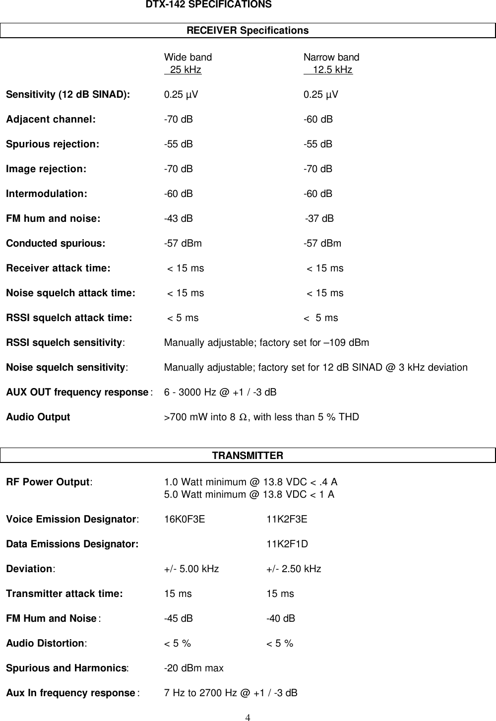
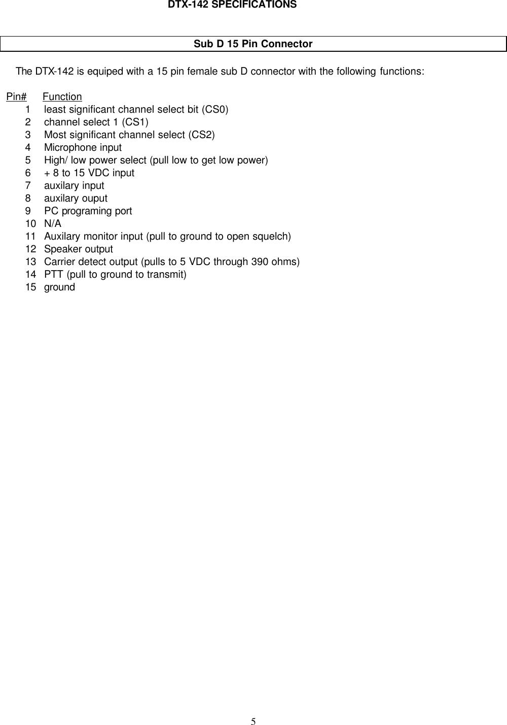
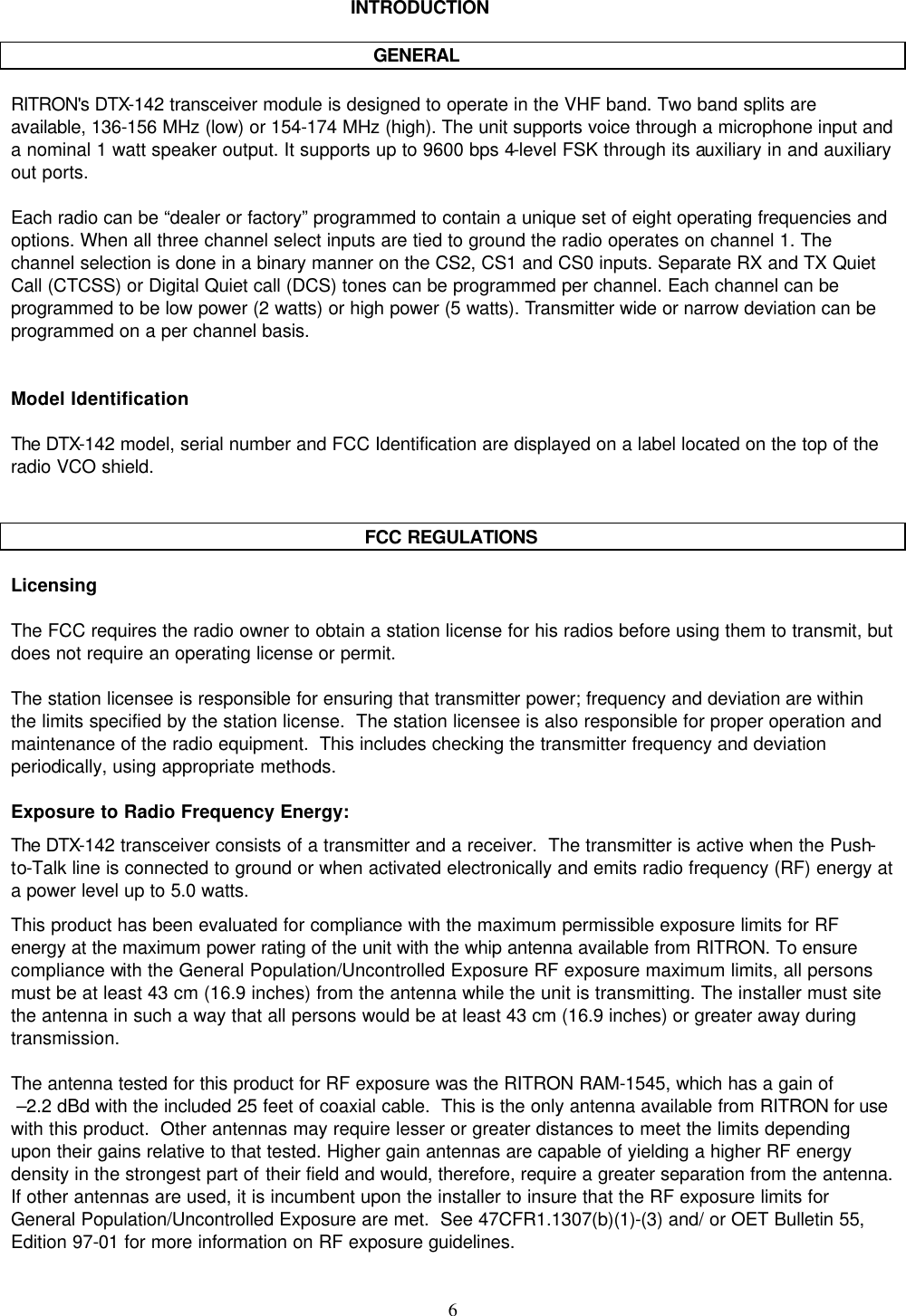
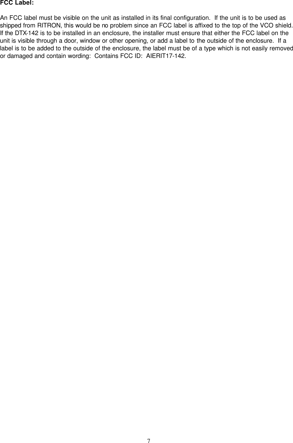
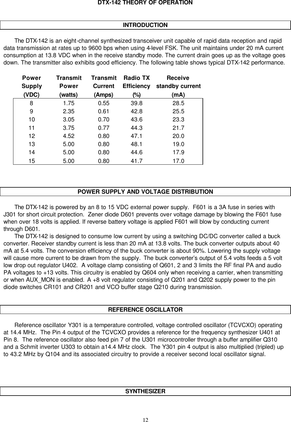
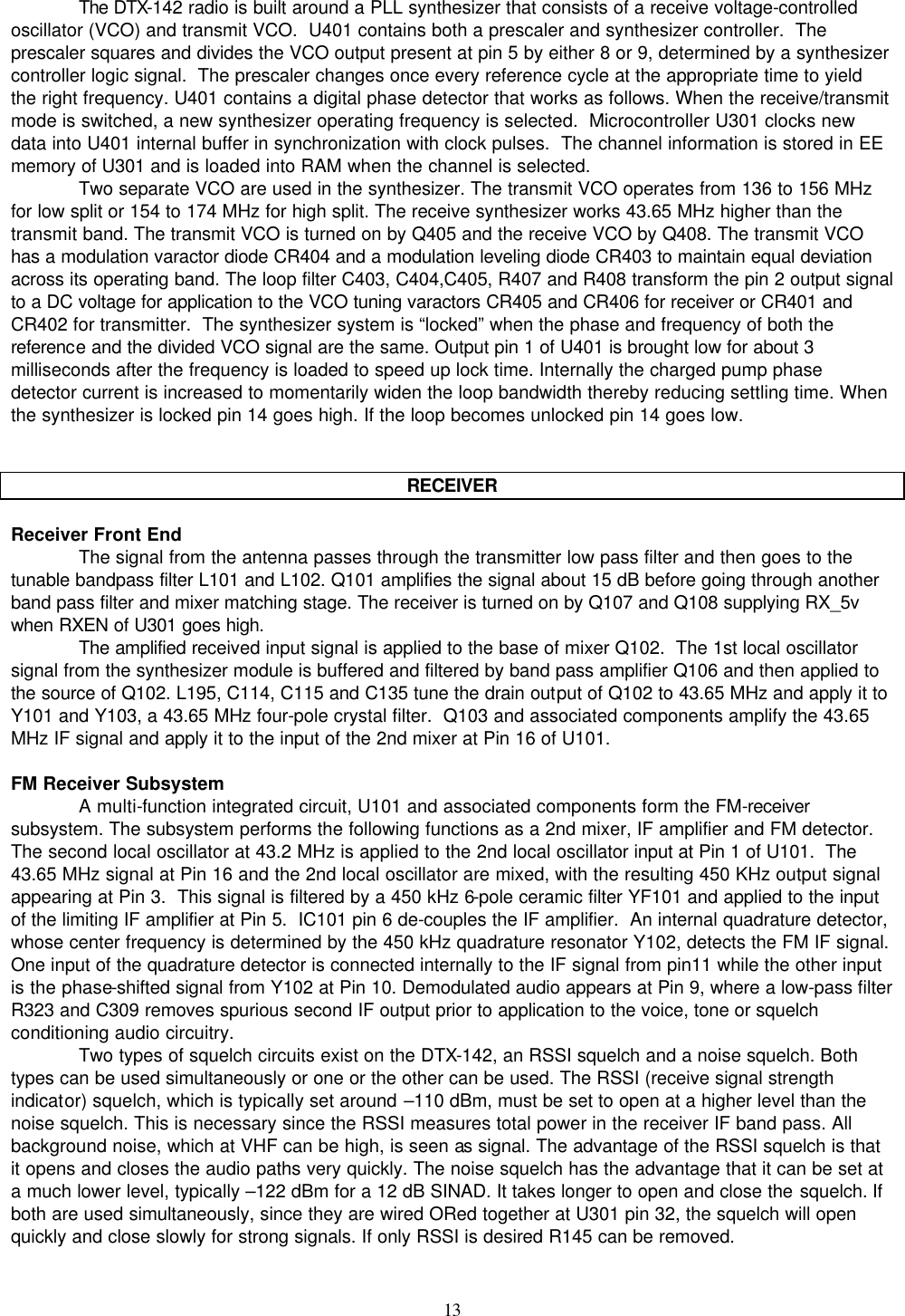
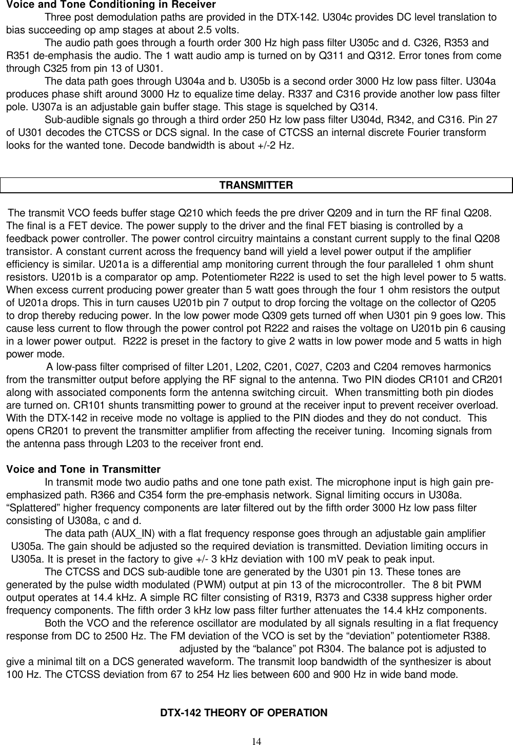
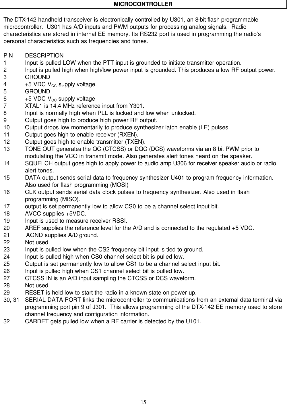
USERS MANUAL
Navigation menu
Upload a User Manual
Namespaces
Wiki Guide
HTML
PDF
Info
Views
User Manual
Discussion / Help
Navigation