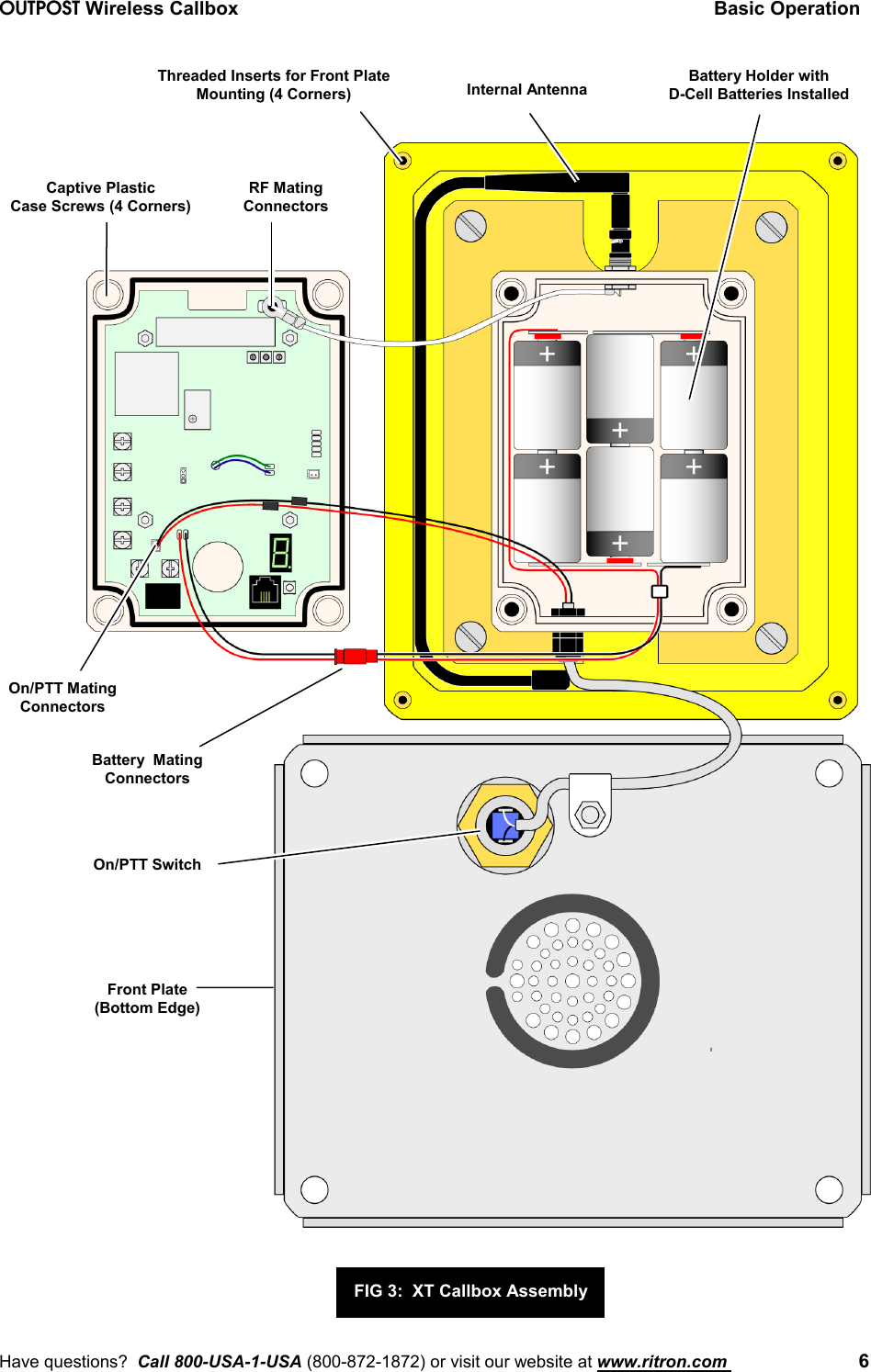
Ritron RIT18-156 VHF-FM CALLBOX TRANSCEIVER User Manual RQX156 InstallOperating
Ritron Inc VHF-FM CALLBOX TRANSCEIVER RQX156 InstallOperating
UserManual.wiki
>
Ritron
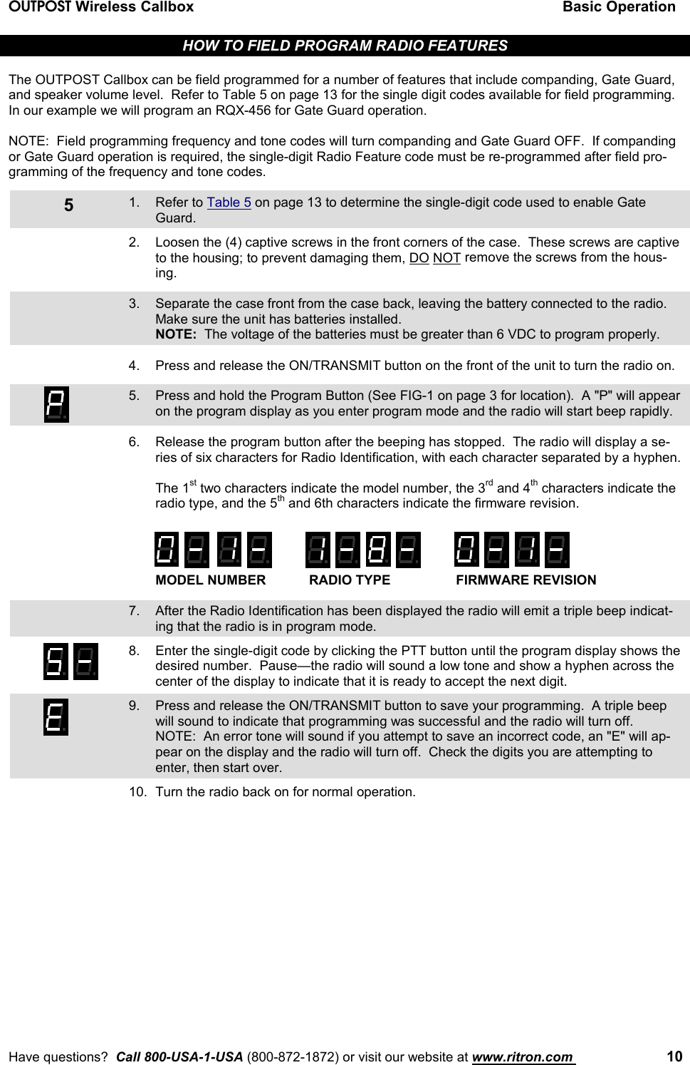
>
RIT18 156 User Manual
Users Manual
Navigation menu
Upload a User Manual
Namespaces
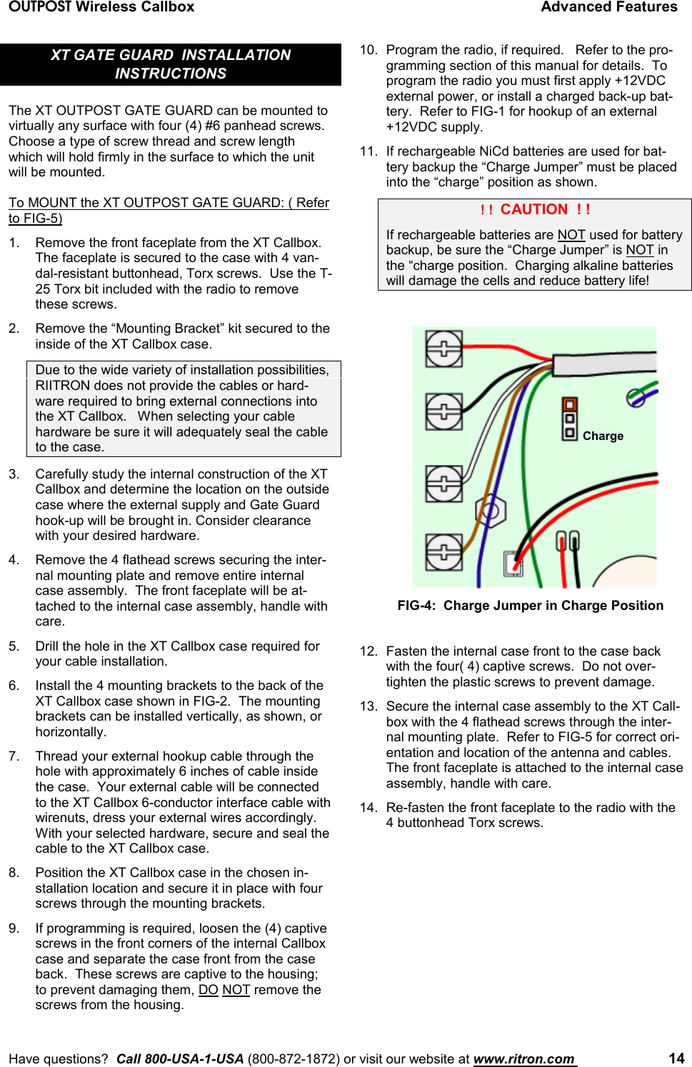
Wiki Guide
HTML
PDF
Info
Views
User Manual
Discussion / Help
Navigation