Ritron RIT21-150 VHF-FM PORTABLE TRANSCEIVER User Manual SLX Series UML 7 05
Ritron Inc VHF-FM PORTABLE TRANSCEIVER SLX Series UML 7 05
Ritron >
USERS MANUAL
Professional Radio
User Guide
P/N 14500054 Rev A 07/05
SLX Series
SLX Series
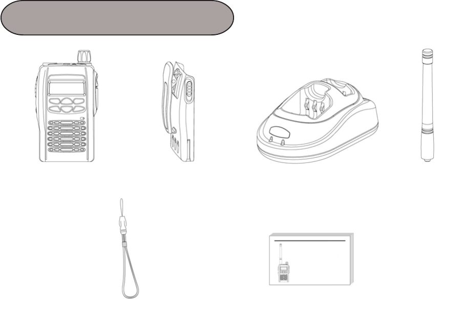
Radio 1700mAh Li-Ion
Battery Pack
Desktop
Rapid Charger
Antenna
Hand Strap User Manual
ITEMS

Contents ............................................................. 1
Radio Overview .................................................. 2
Hot Keys ............................................................. 3
Menu Navigation Chart ....................................... 4
LCD Display Icons .............................................. 5
Attaching the Battery .......................................... 6
Removing the Battery ......................................... 6
Attaching the Antenna ........................................ 7
Removing the Antenna ....................................... 7
Turning the Radio On-Off ................................... 8
Adjusting the Radios Volume ............................. 8
Selecting a Radio Channel ................................. 9
TX/RX Frequency Codes ................................... 10
Tx Tone .............................................................. 11
Rx Tone .............................................................. 11
Key lock .............................................................. 12
Scramble ............................................................ 12
Squelch .............................................................. 13
Ear PTT .............................................................. 13
Approval ............................................................. 14
CONTENTS
1

RADIO OVER
VIEW
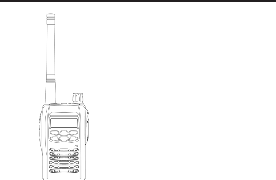
Thank you for purchasing the RITRON SLX-Series
transceivers. Read all instructions carefully and
completely before using transceiver. This instruction
manual contains important operating instructions for
the transceivers.
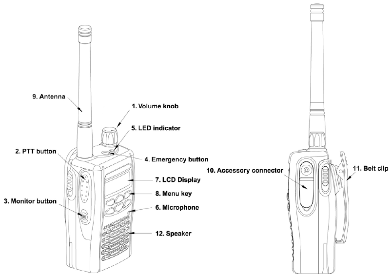
OPERATION AND CONTROL FUNCTIONS
Radio Controls
The numbers below refer to the illustrations on the
inside front cover.
1. On-Off / Volume Knob
Turn the power/volume control knob clockwise
to turn the radio on.
2. Push to Talk Button (PTT)
Push and hold to transmit; release to receive
signal.
3. Monitor Button
Press the Monitor key momentarily to disable
the Tone squelch.
4. Emergency Button
The emergency function allows you to send an
emergency signal quickly and easily to your
Base Station, etc. in case of emergency.
5. LED Indicator
6. Microphone
7. LCD Display
8. Menu Keys
9. Antenna
10. Accessory Connector
Connects headsets, remote speaker/
microphones and other accessories. Replace
attached dust cap when not in use.
11. Belt Clip
Programmable Buttons
All of your radio buttons can be programmed (By
Programming Software) to activate the radio
features.
2
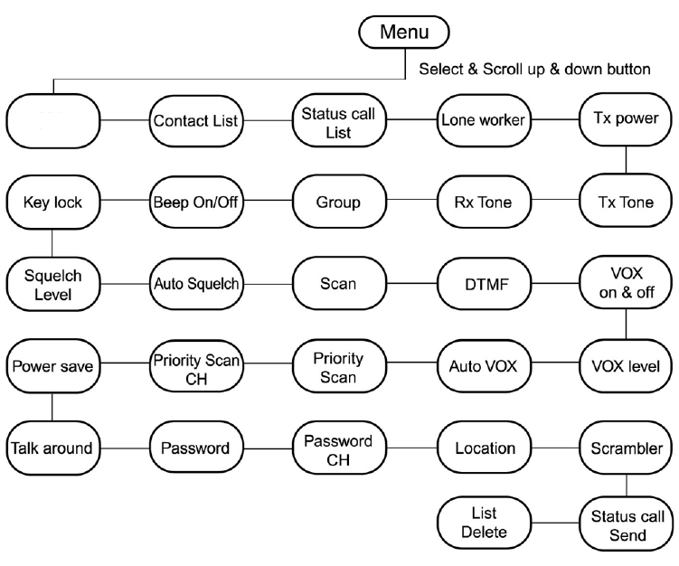
Hot Keys
The front panel buttons (Hot Keys) can be programmed for various features. The following diagram
shows how the Hot Keys are programmed from the factory.
Orange button: Emergency When pressed for 2 seconds, the programmed Emergency
Code is automatically transmitted.
Monitor Button: Monitor Radio programmed with sub-tone: When pressed 1 time, will
disable sub-tone. When pressed 2 times, will disable sub-
tone and carrier squelch.
P1 Button: TX Power Level When pressed will toggle between High Power (4W UHF/
5W VHF) and Low Power (1W).
P2 Button: Contact List When pressed, preprogrammed names from the Contact
List appear in the display. By pressing the PTT button, a
programmed code associated with the Contact List name will
be automatically transmitted.
P3 Button: Scan When pressed, the radio will scan those channels with the
scan function enabled.
Arrow Up Button: Channel/Scroll Up When pressed, the radio channel or feature list selected will
be incremented to the next one.
Arrow Down Button: Channel/Scroll Down When pressed, the radio channel or feature list selected will
be incremented to the next one.
Check Button: Menu Enable When pressed, will display list of features that have been
enabled on the Menu List.
3
TX/RX
Freq
4
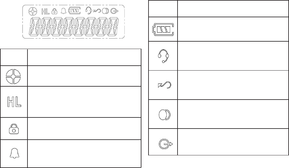
Indicates relative signal strength level.
Power Level Indicator
H is for high power. L is for low
power.
Key Lock Indicator
Appears during key lock function ON.
Alert (Beep) ON/OFF Indicator
Appears when beep sound is turned
ON.
LCD Display and Icons
Battery Level Indicator
Indicates remaining battery power.
VOX Indicator
Appears when VOX function is
turned ON.
Scan Indicator
Appears when Scan function is
activated.
Scrambler Indicator
Appears while the voice scrambler
function is activated.
Talk Around Indicator
Symbol Name and Description
Symbol Name and Description
5
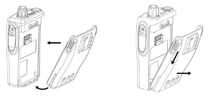
1. Fit the extensions at the bottom of the battery
into the slots at the bottom of the radios body.
2. Press the top part of the battery towards the
radio until you hear a click.
ACCESSORY INFORMATION
Attaching the Battery
1. Turn off the radio, if it is turned on.
2. Slide the battery latches, on both sides of the
battery, downwards.
3. Pull the top part of the battery away from the
radios body, and remove the battery.
Removing the battery
6
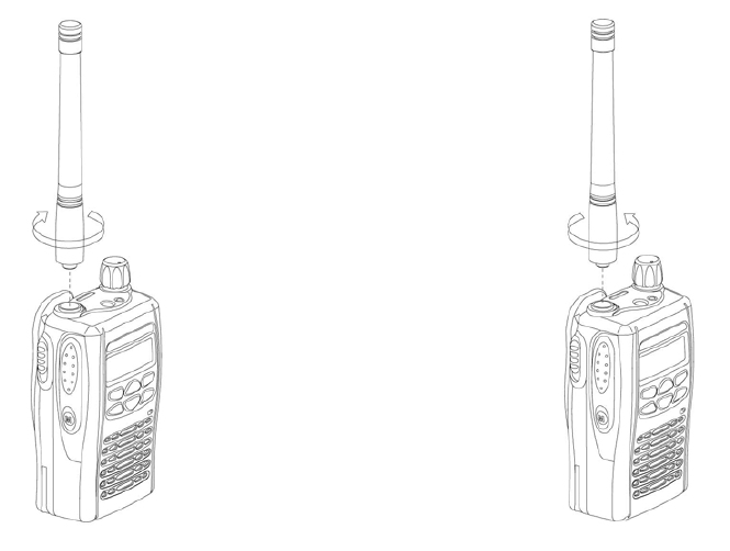
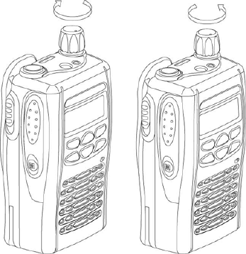
1. Align the threaded end of the antenna with the
radios antenna connector.
2. Turn the antenna clockwise to fasten it.
Attaching the Antenna Removing the Antenna
1. Turn the antenna counterclockwise until you
can remove it.
7
Adjusting the Radios Volume
Turn the On-Off/Volume Control knob to adjust the
sound level.
RADIO OPERATION
Turning the Radio On or Off
To turn the radio on, turn the On-Off/Volume Control
knob clockwise.
To turn the radio off, turn the On-Off/Volume Control
knob counterclockwise until you hear a click.
8
Select the desired channel by using the Up/Down
Key. Each press increases/decreases the channel
number. When held down, the channels increase
continuously.
Select the desires channel by using the Down Key.
Each press decreases the channel number. When
held down, the channels decreases continously.
Transmission Signal
To transmit, monitor the channel, and make sure it is
clear. THIS IS AN FCC REQUIREMENT!
To transmit, press and hold the PTT switch. Speak
into the microphone area of the panel grill in a normal
voice level. To return to the Receive mode, release
the PTT switch.
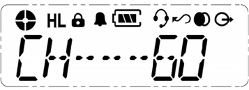
Selecting a Radio Channel
This radio offers up to 60 channels.
User Program Mode
In order to make changes to the features of the
radio via the menu list, the radio must first be
placed in User Program Mode.
To put the radio into User Program Mode:
1. Make sure On/Off Volume control is in the Off
position.
2. Press the Menu button while rotating the On/
Off Volume control to the On position.
3. A short beep will be heard and the characters
CH-01 will be shown in the display.
4. Use the Up/Down arrows to select the channel
to be changed.
5. Once the channel is selected, press the menu
button and the characters FREQ will be
shown in the display.
6. Use the Up/Down arrows to select the feature
to be changed.
7. After all changes have been made and saved,
rotate the ON/Off volume control to the Off
position and then back to the On position for
normal radio operation.
9

TX/RX Frequency
To change the transmit and receive frequency of a
certain channel:
1. After radio is placed into User Program Mode
and the desired channel to be changed is
selected, use the Up/Down arrows to select the
menu feature FREQ.
2. Press the menu button and the characters 00
will be displayed in the display.
3. Use the Up/Down arrows to select the 2-digit
code corresponding to the desired Rx/Tx
frequency as shown in Table 1 Programmable
Frequency Codes.
4. When the desired code is displayed, press the
menu button to save the selection.
5. To return to normal operation, turn radio Off
and then back On.
Table 1. Programmable Frequency Codes
VHF MURS
Code No. MHz Color Dot Bandwidth(kHz)
01 154.6000 Green Dot 25
02 154.5700 Blue Dot 25
19 151.8200 MURS 12.5
20 151.8800 MURS 12.5
21 151.9400 MURS 12.5
22 154.6000 MURS/Green 12.5
23 154.5700 MURS/Blue 12.5
00 DELETE Code
VHF Business Band
Code No. MHz Color Dot Bandwidth(kHz)
03 151.6250 Red Dot 25
04 151.9550 Purple Dot 25
05 151.9250 25
06 154.5400 25
07 154.5150 25
08 154.6550 25
09 151.6850 25
10 151.7150 25
11 151.7750 25
12 151.8050 25
13 151.8350 25
14 151.8950 25
15 154.4900 25
16 151.6550 25
17 151.7450 25
18 151.8650 25
24 151.7000 12.5
25 151.7600 12.5
26 152.7000 25
00 DELETE Code
Per FCC rules and regulations, a given radio must not be
programmed to contain a mix of both VHF Business Band and
VHFMURS frequencies.
10
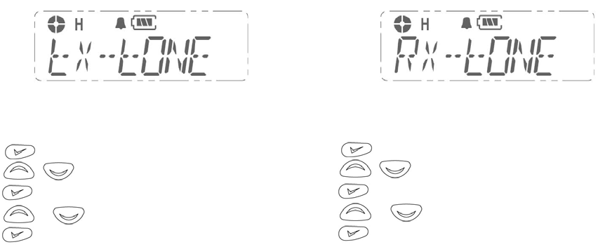
Tx Tone
This function is used to change Tx Tone such as
CTCSS, DCS.
Rx Tone
This function is used to change Rx Tone such as
CTCSS, DCS.
Method:
1. to enter Menu Mode.
2. to scroll list until Tx Tone.
3. to select.
4. or to select CTCSS or DCS.
5. to select.
There are 38 CTCSS codes (1~38)
There are 83 DCS codes (101~183)
0 means no Tone.
Method:
1. to enter Menu Mode.
2. to scroll list until Tx Tone.
3. to select.
4. or to select CTCSS or DCS.
5. to select.
There are 38 CTCSS codes (1~38)
There are 83 DCS codes (101~183)
0 means no Tone.
11
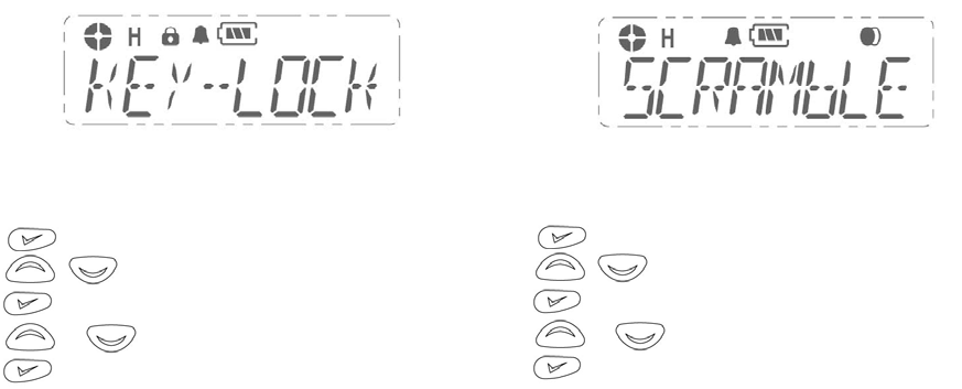
Key Lock
Key Lock Indicator
Appears when key lock function is ON.
Scrambler
This function provides higher communication
security.
Method:
1. to enter Menu Mode.
2. to scroll list until Key Lock.
3. to select.
4. or to select lock or unlock.
5. to select.
Method:
1. to enter Menu Mode.
2. to scroll list until Scrambler.
3. to select.
4. or to select on or off.
5. to select.
12
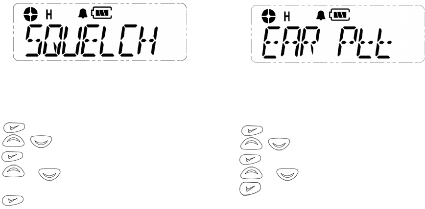
Squelch Level
This function sets the point at which the radios
receiver will open depending upon the signal
strength of the transmitted signal.
Ear PTT
This function allows for the radios internal
microphone to be enabled when an audio
accessory is plugged in.
Method:
1. to enter Menu Mode.
2. to scroll list until EAR PTT.
3. to select.
4. or to select ON or OFF.
5. to save and return to normal operation.
Method:
1. to enter Menu Mode.
2. to scroll list until Squelch.
3. to select.
4. or to set level; the larger the number,
the more signal is needed to open the receiver.
5. to save and return to normal operation.
13

APPROVAL
FCC RF exposure limits. A proper antenna is the antenna
supplied with this radio by the manufacturer for use with
this radio.
Do not transmit for more than 50% of total radio use time
(50% duty cycle). Transmitting more than 50% of the
time can cause FCC RF exposure compliance
requirements to be exceeded.
Always use the supplied accessories (antenna, batteries,
belt clips, speaker/mic, etc.)
Use of unauthorized accessories can cause the FCC RF
exposure compliance requirements to be exceeded.
Always keep the antenna at least 2.5 cm (1 inch) away
from the body when transmitting and only use the belt-
clips, when attaching the radio to your belt, etc., to ensure
FCC RF exposure compliance requirements are not being
exceeded.
2. CE APPROVAL
This transceiver meets the following essential
requirement.
EN 300 086-1/2
1. FCC APPROVAL
FCC ID: SLX-100 AIERIT21-150
SLX-400 AIERIT21-450
Safety Training Information
Your RITRON FM Handheld Transceiver generates RF
electromagnetic energy during transmit mode.
This radio is designed for and classified as Controlled
Exposure/Occupation Environment, meaning it must be
used only during the course of employment by individuals
aware of the hazards, and the ways to minimize such
hazards.
This radio is not for use by the General Population/
Uncontrolled Environment.
This radio complies with FCC RF radiation exposure limits
set forth for a controlled environment.
This radio should be installed and operated with a
minimum distance of 2.5 centimeters between the radio
and yoru body. Therefore, to ensure that your exposure
to RF electromagnetic energy is within the FCC allowable
limits for occupational use, always follow below
information.
Do not operate the radio without a proper antenna as this
may damage the radio and may also cause you to exceed
0678 !
14

505 West Carmel Drive Carmel, IN 46032 USA
P. O. Box 1998 Carmel, IN 46082-1998 USA
Ph: 317-846-1201 Fax: 317-846-4978 Email: ritron@ritron.com Website: www.ritron.com