Ritron RIT24-160 VHF MOBILE TRANSCEIVER User Manual RITRON
Ritron Inc VHF MOBILE TRANSCEIVER RITRON
UserManual.wiki
>
Ritron
>
RIT24 160 User Manual
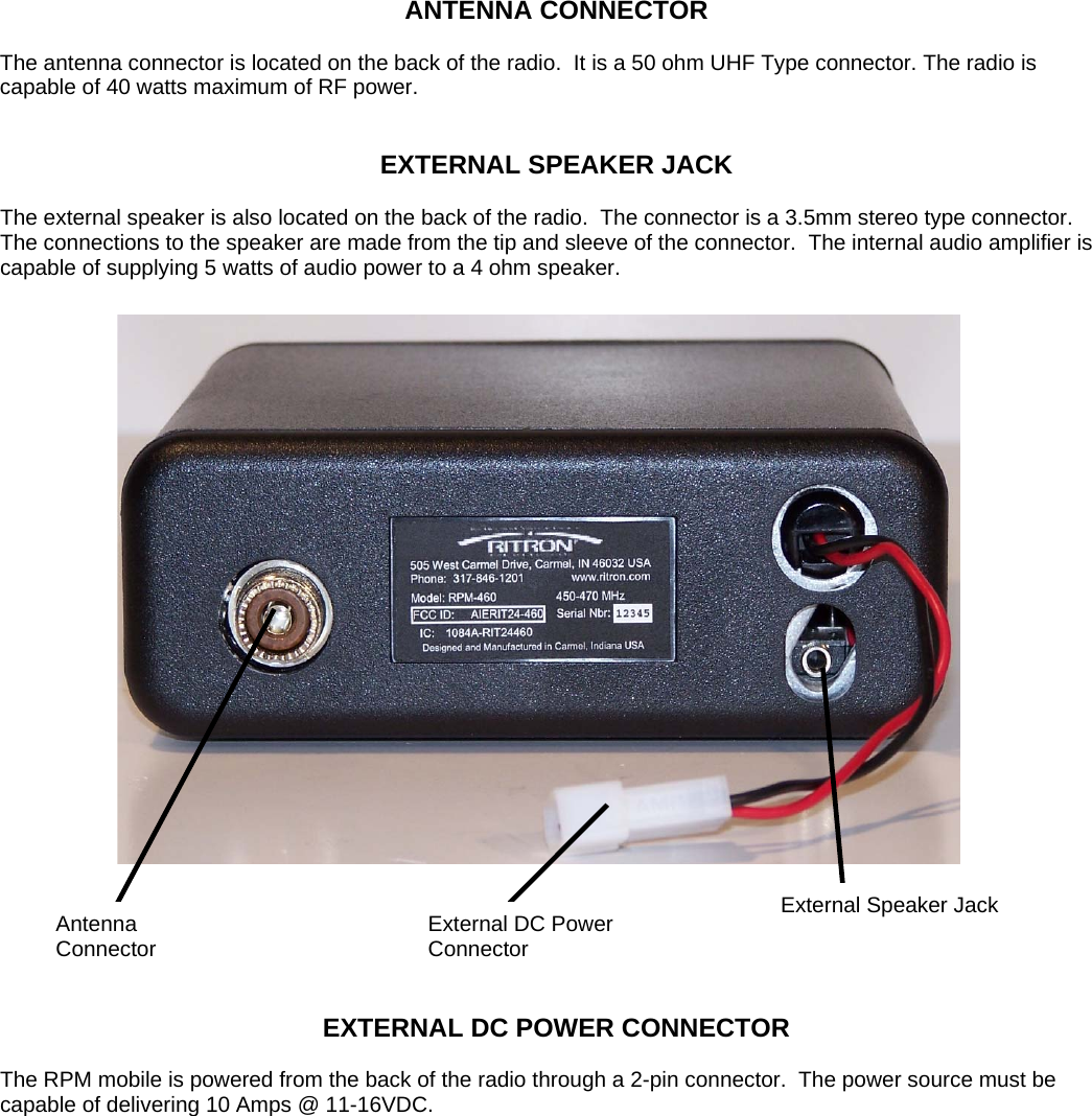
USERS MANUAL
Navigation menu
Upload a User Manual
Namespaces
Wiki Guide
HTML
PDF
Info
Views
User Manual
Discussion / Help
Navigation