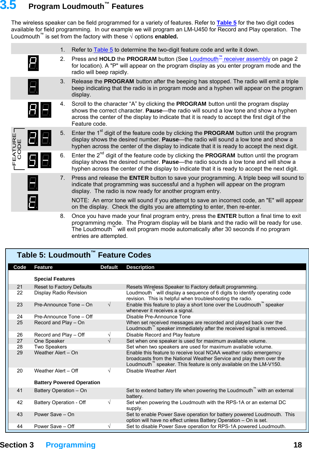
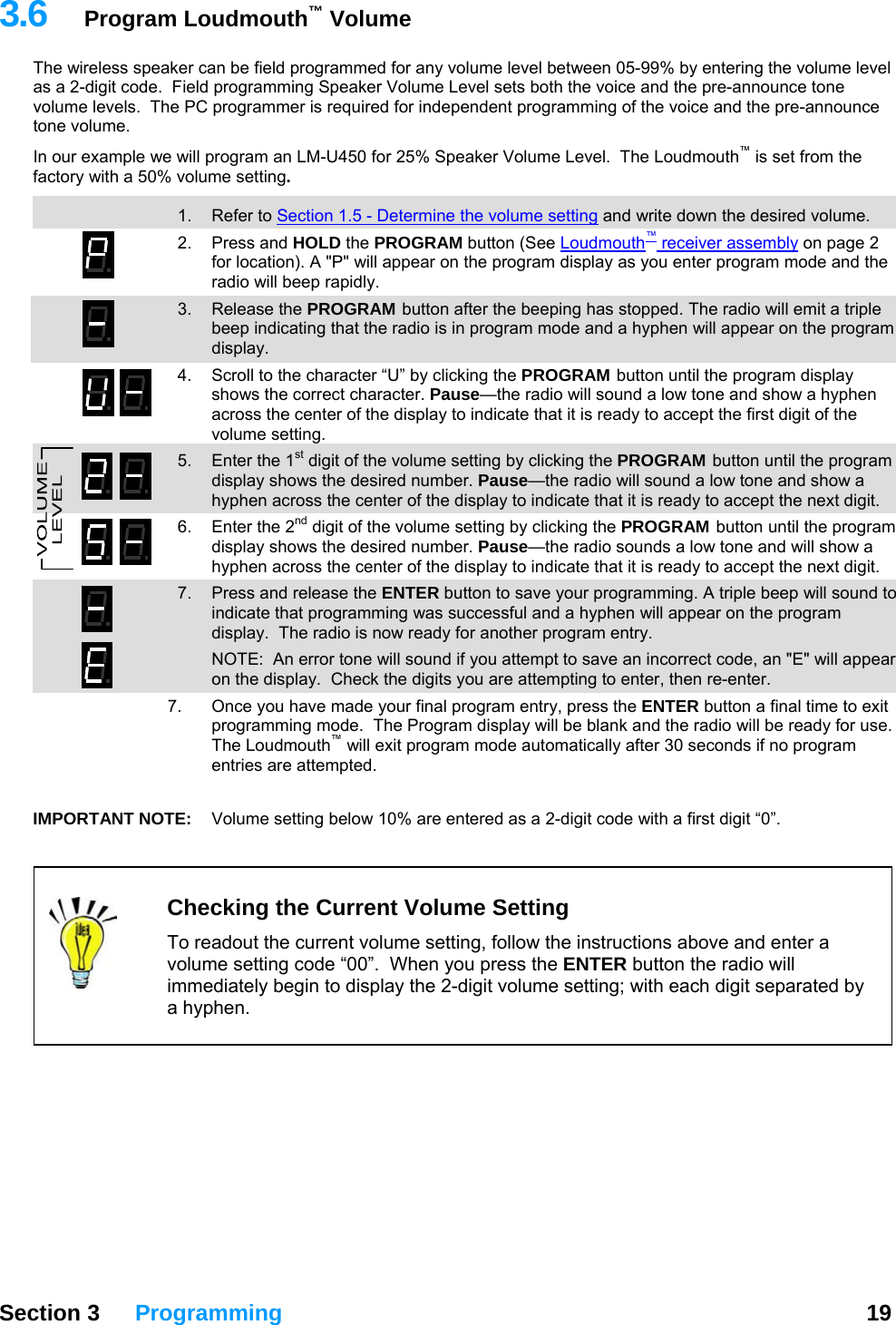
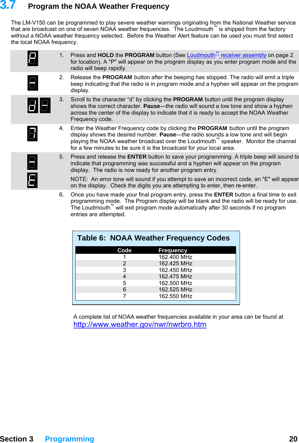
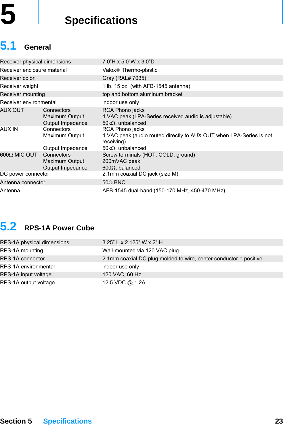
Ritron RIT27-150 VHF-FM RECEIVER User Manual TYPE OF EXHIBIT
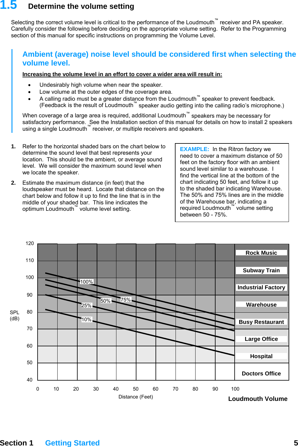
Ritron Inc VHF-FM RECEIVER TYPE OF EXHIBIT
UserManual.wiki
>
Ritron
>
RIT27 150 User Manual
USERS MANUAL
Navigation menu
Upload a User Manual
Namespaces
Wiki Guide
HTML
PDF
Info
Views
User Manual
Discussion / Help
Navigation
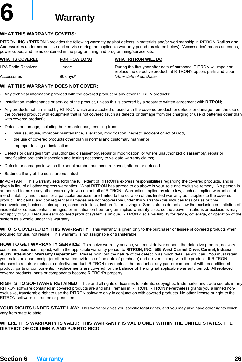
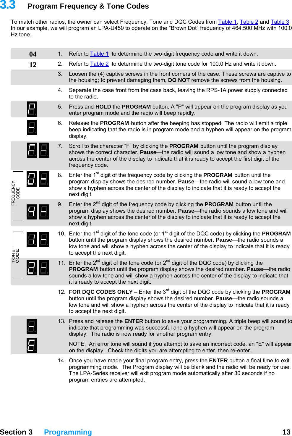
![Section 3 Programming 13 3 Programming For most installations the Loudmouth™ can be programmed in the field without the need for Ritron PC Programmer 12.0.1. Field programming is accomplished in 3 easy steps. First, the radio frequency and tone codes are entered. Second, the selective signaling code is entered (if used). Third, the Loudmouth™ options and volume setting are entered. 3.1 Loudmouth™ Field Programming Overview Press ENTER ProgramodesC Table Codes Enter a 2-digit Frequency code from Table 1 and a 2-digit QC code from Table 2 or nter a 2-digit Frequency code from Table 1 and a 3-digit DQC code from Table 3. E or Enter a 2-digit, 2-Tone Paging code from Table 4 Enter any 3 – digit Selcall Paging Code. 7- E r a ™nte 2-digit Loudmouth Feature code from Table 5 to: • Enable or disable a Pre-Announce Tone. • Enable or disable Record and Play operation. ly) • Enable or disable Weather Alert feature (VHF models onon. • Enable or disable Battery Powered Operati• Enable or Disable Power Save operation. • Reset L udmouth to Factory default programming. o Enter the desired Speaker Volume Level as a 2 –digit number from 05 – 99. Enter the 1-digit NOAA Weather Frequency code from Table 6 (VHF models only) This only programs the NOAA weather frequency, the Weather Alert feature must be enabled using the Special Features code in Table 5. Place the Loudmouth receiver into Program mode. Use PROGRAM button to scroll to one of the following Program Code characters: [F], [C], [A], [U], [d] Pause, a hyphen will appear on the display. Using the PROGRAM button to save programming entry. button, enter the desired Table Code. Press ENTER button a second time to Exit programming. or Proceed with next program entry.](https://usermanual.wiki/Ritron/RIT27-150/User-Guide-849060-Page-17.png)
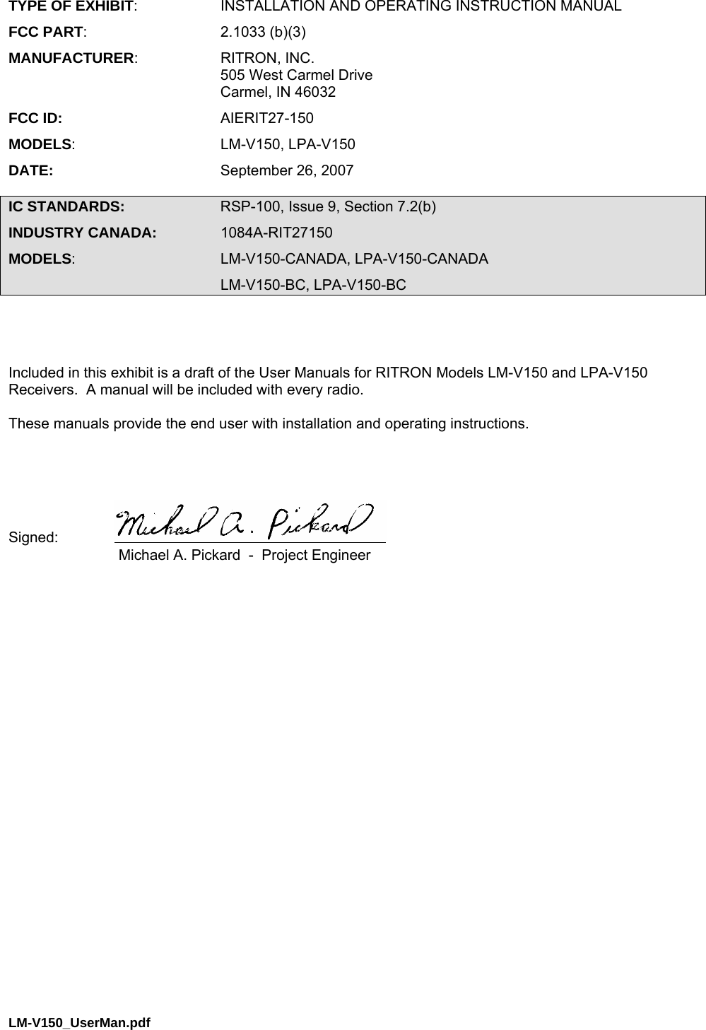
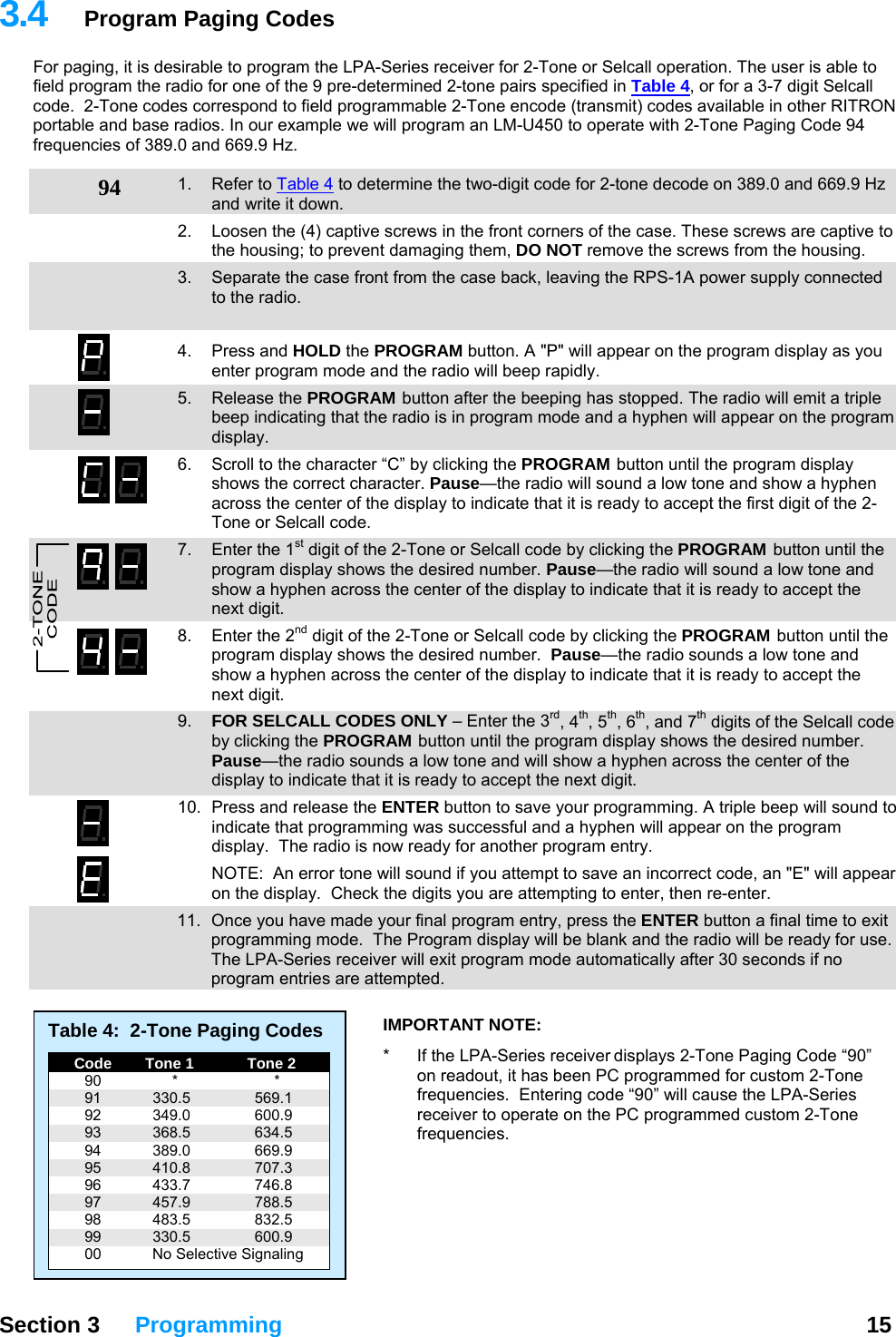
![Field Programming Map Feature Decision Programming Frequency Code from Table No Custom frequency requires PC programming or Yes Interference Eliminator Tone Code QC Enter Frequency & Tone codes [F] or DQC Selective Paging None Enter No Paging Code [C] or Selcall Enter 3-7 digit Selcall Code [C] or 2-Tone 2-Tone Code from Table No Custom 2-Tone requires PC programming or Yes Enter 2-Tone Code [C] Set Speaker Volume Enter Volume Code [U] Number of speakers 1 Enter 1 Speaker Code [A] or 2 Enter 2 Speaker Code [A] Record and Play On Enter Record and Play On Code [A] or Off Enter Record and Play Off Code [A] Pre-Announce Tone On Enter Pre-Announce On Code [A] or Off Enter Pre-Announce Off Code [A] Battery Powered Operation Off Enter Battery Operation Off Code [A] or On Enter Battery Operation On Code [A] Power Saver Off Enter Power Save Off Code [A] or On Enter Power Save On Code [A] NOAA Frequency UHF Not available at UHF or VHF Enter NOAA Weather Code [d] Weather Alert Off Enter Weather Alert Off Code [A] or On Enter Weather Alert On Code [A] Section 5 Specifications 28](https://usermanual.wiki/Ritron/RIT27-150/User-Guide-849060-Page-32.png)
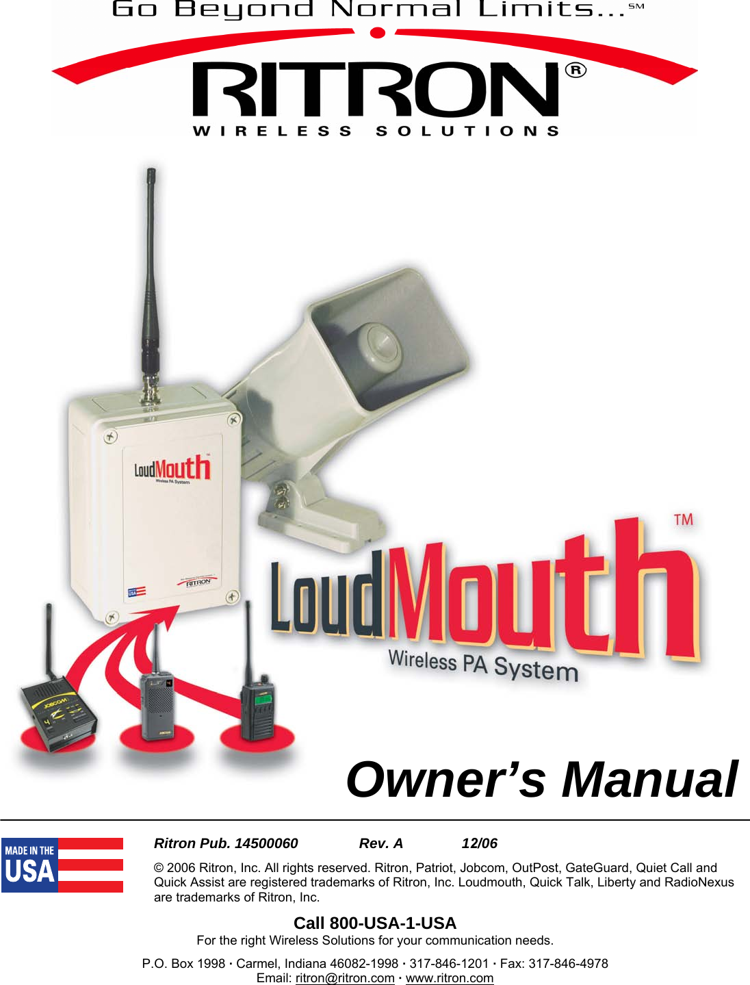
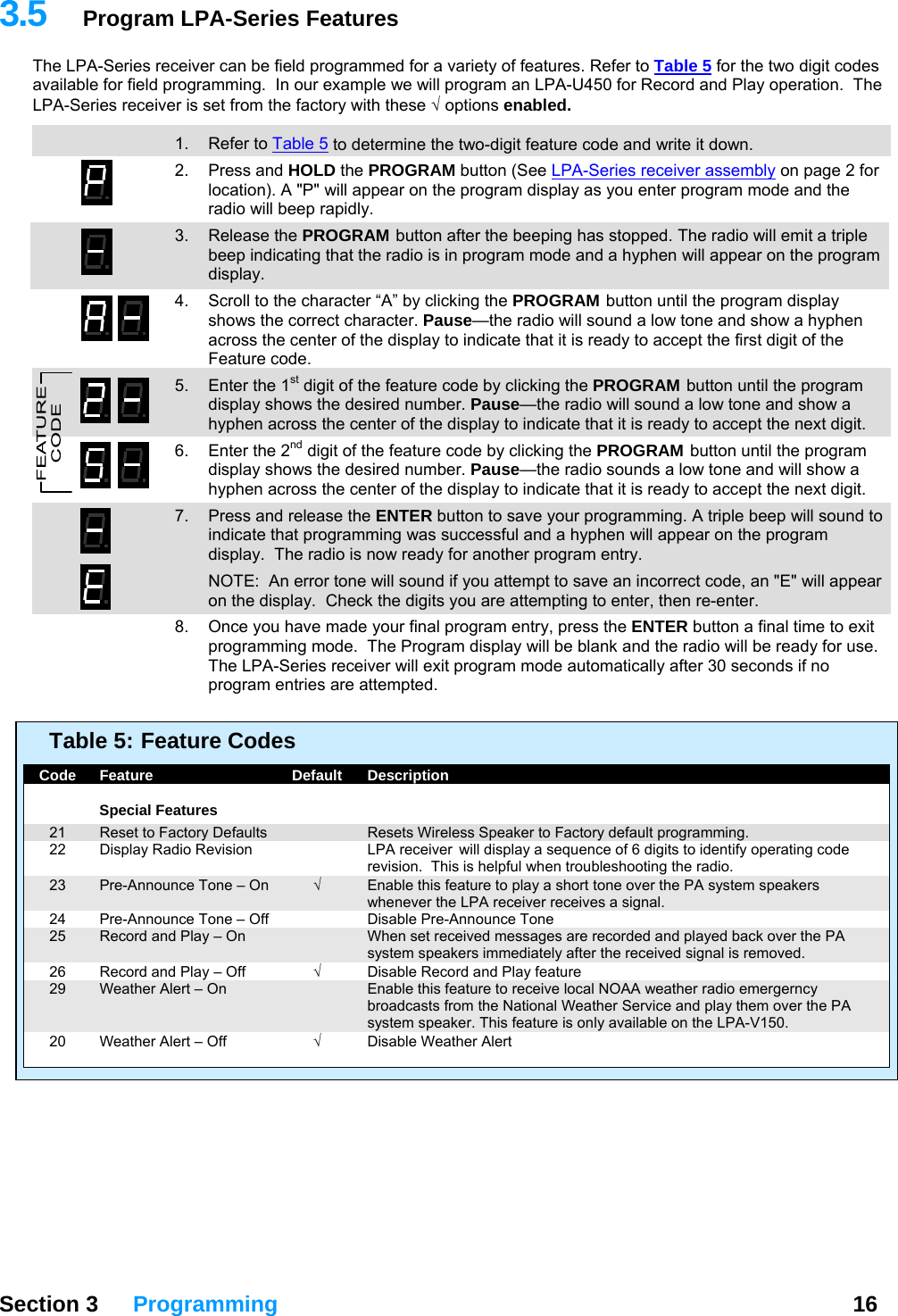
![3 Programming For most installations the LPA-Series receiver can be programmed in the field without the need for Ritron PC Programmer 12.0.1. Field programming is accomplished in 3 easy steps. First, the radio frequency and tone codes are entered. Second, the selective signaling code is entered (if used). Third, the LPA-Series options and volume setting are entered. 3.1 LPA-Series Field Programming Overview Press ENTER Section 3 Programming 11 Program odesC Table Codes Enter a 2-digit Frequency code from Table 1 and a 2-digit QC code from Table 2 or nter a 2-digit Frequency code from Table 1 and a 3-digit DQC code from Table 3. E or Enter a 2-digit, 2-Tone Paging code from Table 4 Enter any 3 – digit Selcall Paging Code. 7- E r nte a 2-digit Feature code from Table 5 to: • Enable or disable a Pre-Announce Tone. • Enable or disable Record and Play operation. • Enable or disable Weather Alert feature (VHF models only) • Reset LPA-Series receiver to Factory default programming. Enter the desired Speaker Volume Level as a 2 –digit number from 05 – 99. Enter the 1-digit NOAA Weather Frequency code from Table 6 (VHF models only) This only programs the NOAA weather frequency, the Weather Alert feature must be enabled using the Special Features code in Table 5. Place the LPA-Series receiver into Program mode. Use PROGRAM button to scroll to one of the following Program Code characters: [F], [C], [A], [U], [d] Pause, a hyphen will appear on the display. Using the PROGRAM button to save programming entry. button, enter the desired Table Code. Press ENTER button a second time to Exit programming. or Proceed with next program entry.](https://usermanual.wiki/Ritron/RIT27-150/User-Guide-849060-Page-46.png)

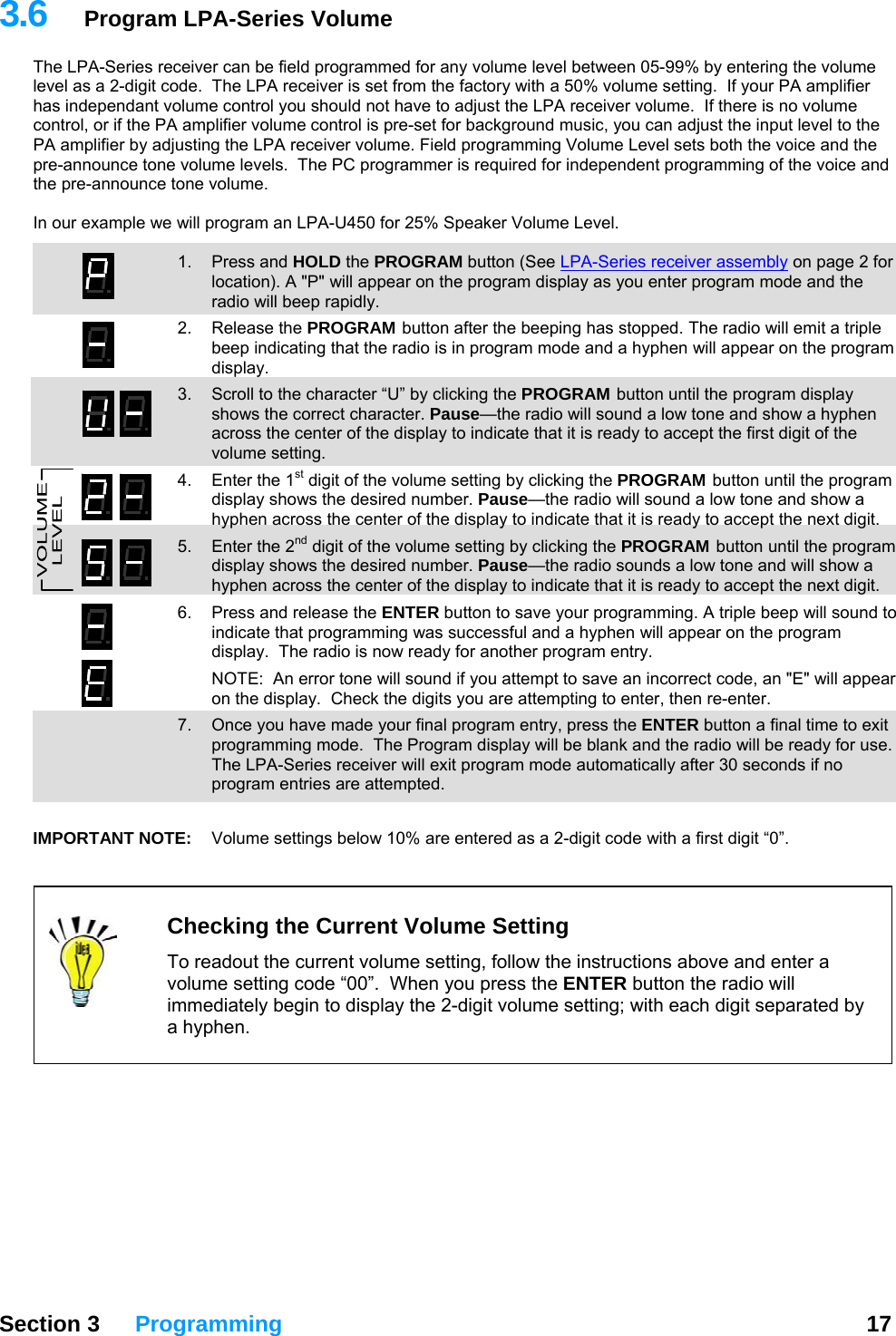
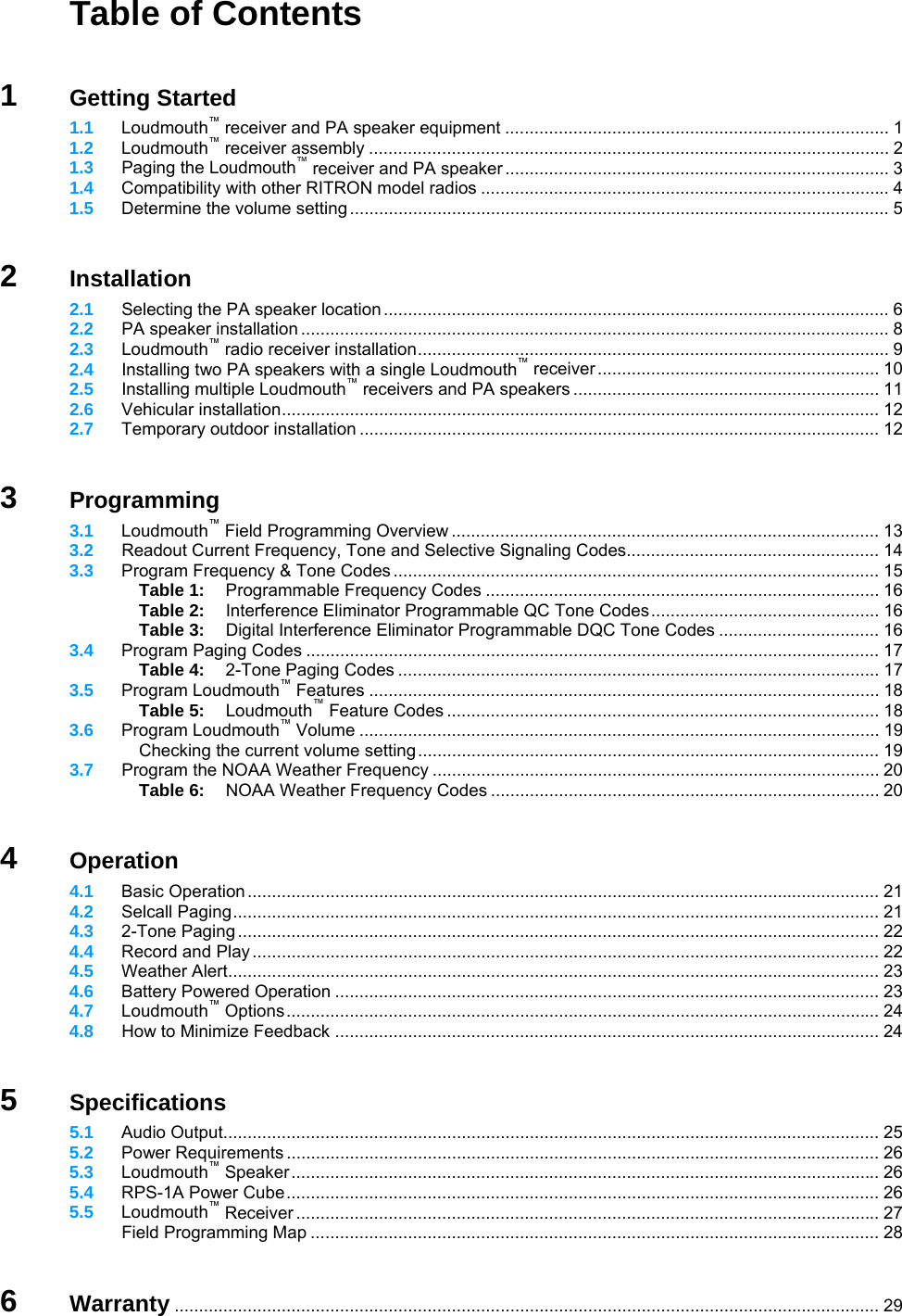
![Field Programming Map Feature Decision Programming Frequency Code from Table No Custom frequency requires PC programming or Yes Interference Eliminator Tone Code QC Enter Frequency & Tone codes [F] or DQC Selective Paging None Enter No Paging Code [C] or Selcall Enter 3-7 digit Selcall Code [C] or 2-Tone 2-Tone Code from Table No Custom 2-Tone requires PC programming or Yes Enter 2-Tone Code [C] Set Volume Enter Volume Code [U] Record and Play On Enter Record and Play On Code [A] or Off Enter Record and Play Off Code [A] Pre-Announce Tone On Enter Pre-Announce On Code [A] or Off Enter Pre-Announce Off Code [A] Battery Powered Operation Off Enter Battery Operation Off Code [A] or On Enter Battery Operation On Code [A] Power Saver Off Enter Power Save Off Code [A] or On Enter Power Save On Code [A] NOAA Frequency UHF Not available at UHF or VHF Enter NOAA Weather Code [d] Weather Alert Off Enter Weather Alert Off Code [A] or On Enter Weather Alert On Code [A] Section 5 Specifications 25](https://usermanual.wiki/Ritron/RIT27-150/User-Guide-849060-Page-60.png)