Ritron RIT27-450 UHF-FM RECEIVER User Manual TYPE OF EXHIBIT
Ritron Inc UHF-FM RECEIVER TYPE OF EXHIBIT
Ritron >
USER MANUAL

TYPE OF EXHIBIT: INSTALLATION AND OPERATING INSTRUCTION MANUAL
FCC PART: 2.1033 (b)(3)
MANUFACTURER: RITRON, INC.
505 West Carmel Drive
Carmel, IN 46032
FCC ID: AIERIT27-450
MODELS: LM-U450, LPA-U450
DATE: September 18, 2007
IC STANDARDS: RSP-100, Issue 9, Section 7.2(b)
INDUSTRY CANADA: 1084A-RIT27450
MODELS: LM-U450-CANADA, LPA-U450-CANADA
Included in this exhibit is a draft of the User Manuals for RITRON Models LM-U450 and LPA-U450
Receivers. A manual will be included with every radio.
These manuals provides the end user with installation and operating instructions.
Signed:
Michael A. Pickard - Project Engineer
LM-U450_UserMan.pdf
Ritron Pub. 14500060 Rev. A 12/06
© 2006 Ritron, Inc. All rights reserved. Ritron, Patriot, Jobcom, OutPost, GateGuard, Quiet Call and
Quick Assist are registered trademarks of Ritron, Inc. Loudmouth, Quick Talk, Liberty and RadioNexus
are trademarks of Ritron, Inc.
Call 800-USA-1-USA
For the right Wireless Solutions for your communication needs.
P.O. Box 1998 · Carmel, Indiana 46082-1998 · 317-846-1201 · Fax: 317-846-4978
Email: ritron@ritron.com · www.ritron.com
Owner’s Manual
Table of Contents
1 Getting Started
1.1 Loudmouth™ receiver and PA speaker equipment ............................................................................... 1
1.2 Loudmouth™ receiver assembly ........................................................................................................... 2
1.3 Paging the Loudmouth™ receiver and PA speaker ............................................................................... 3
1.4 Compatibility with other RITRON model radios .................................................................................... 4
1.5 Determine the volume setting............................................................................................................... 5
2 Installation
2.1 Selecting the PA speaker location........................................................................................................ 6
2.2 PA speaker installation ......................................................................................................................... 8
2.3 Loudmouth™ radio receiver installation................................................................................................. 9
2.4 Installing two PA speakers with a single Loudmouth™ receiver.......................................................... 10
2.5 Installing multiple Loudmouth™ receivers and PA speakers ............................................................... 11
2.6 Vehicular installation........................................................................................................................... 12
2.7 Temporary outdoor installation ........................................................................................................... 12
3 Programming
3.1 Loudmouth™ Field Programming Overview ........................................................................................ 13
3.2 Readout Current Frequency, Tone and Selective Signaling Codes.................................................... 14
3.3 Program Frequency & Tone Codes.................................................................................................... 15
Table 1: Programmable Frequency Codes ................................................................................. 16
Table 2: Interference Eliminator Programmable QC Tone Codes............................................... 16
Table 3: Digital Interference Eliminator Programmable DQC Tone Codes ................................. 16
3.4 Program Paging Codes ...................................................................................................................... 17
Table 4: 2-Tone Paging Codes ................................................................................................... 17
3.5 Program Loudmouth™ Features ......................................................................................................... 18
Table 5: Loudmouth™ Feature Codes ......................................................................................... 18
3.6 Program Loudmouth™ Volume ........................................................................................................... 19
Checking the current volume setting............................................................................................... 19
3.7 Program the NOAA Weather Frequency ............................................................................................ 20
Table 6: NOAA Weather Frequency Codes ................................................................................ 20
4 Operation
4.1 Basic Operation.................................................................................................................................. 21
4.2 Selcall Paging..................................................................................................................................... 21
4.3 2-Tone Paging.................................................................................................................................... 22
4.4 Record and Play................................................................................................................................. 22
4.5 Weather Alert...................................................................................................................................... 23
4.6 Battery Powered Operation ................................................................................................................ 23
4.7 Loudmouth™ Options.......................................................................................................................... 24
4.8 How to Minimize Feedback ................................................................................................................ 24
5 Specifications
5.1 Audio Output....................................................................................................................................... 25
5.2 Power Requirements.......................................................................................................................... 26
5.3 Loudmouth™ Speaker......................................................................................................................... 26
5.4 RPS-1A Power Cube.......................................................................................................................... 26
5.5 Loudmouth™ Receiver ........................................................................................................................ 27
Field Programming Map ..................................................................................................................... 28
6 Warranty ................................................................................................................................................. 29
1 Getting Started
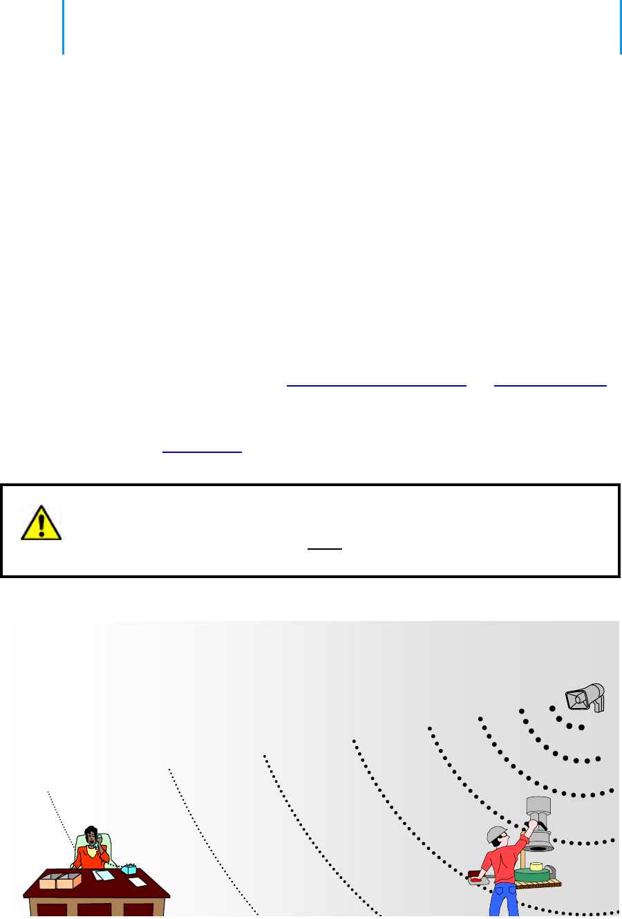
The Loudmouth™ is a radio receiver that allows you to use your portable, base
station or mobile 2-way radio to deliver voice messages directly to a PA speaker
up to 2 miles away. The receiver and PA speaker is the ideal solution where hard-
wired PA installation is simply impossible, too expensive, or temporary.
Your Loudmouth™ receiver and PA speaker has been designed so that you can set
it up quickly and start using it right away.
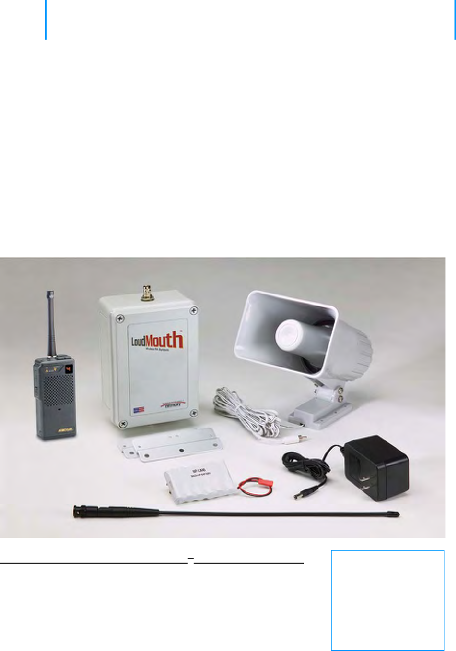
1.1 Loudmouth™ receiver and PA speaker equipment
Check your package to be sure you received all the equipment necessary to install the Loudmouth™ receiver and
PA horn speaker.
Antenna
* Portable Radio
(optional)
Power Cube
Horn Speaker
Backup Battery
Loudmouth™ Receiver
Mounting Brackets
Need
replacement
items?
Contact your Ritron
dealer, or Ritron
directly at
800-USA-1-USA
List of items included with your Loudmouth™ receiver and PA speaker:
LM-U450 or LM-V150........Loudmouth™ Radio Receiver 5W audio amplifier
05500040 ..........................Horn Speaker with RCA phono plug and 25 ft. cable
RPS-1A .............................Power Cube, 1A with 2.1mm coaxial DC connector
BP-LM9.............................Emergency Backup battery pack, 10.8VDC, 800mAH
AFB-1545..........................Wideband Antenna with BNC connector
RK-RQX-MB .....................Mounting Brackets
14500060 ..........................Loudmouth™ User Manual
Section 1 Getting Started 1
* Ritron portable JMX-446D is also included when ordering the LM-U450SYSTEM, and the JMX-144D
portable is included when ordering the LM-V150SYSTEM.
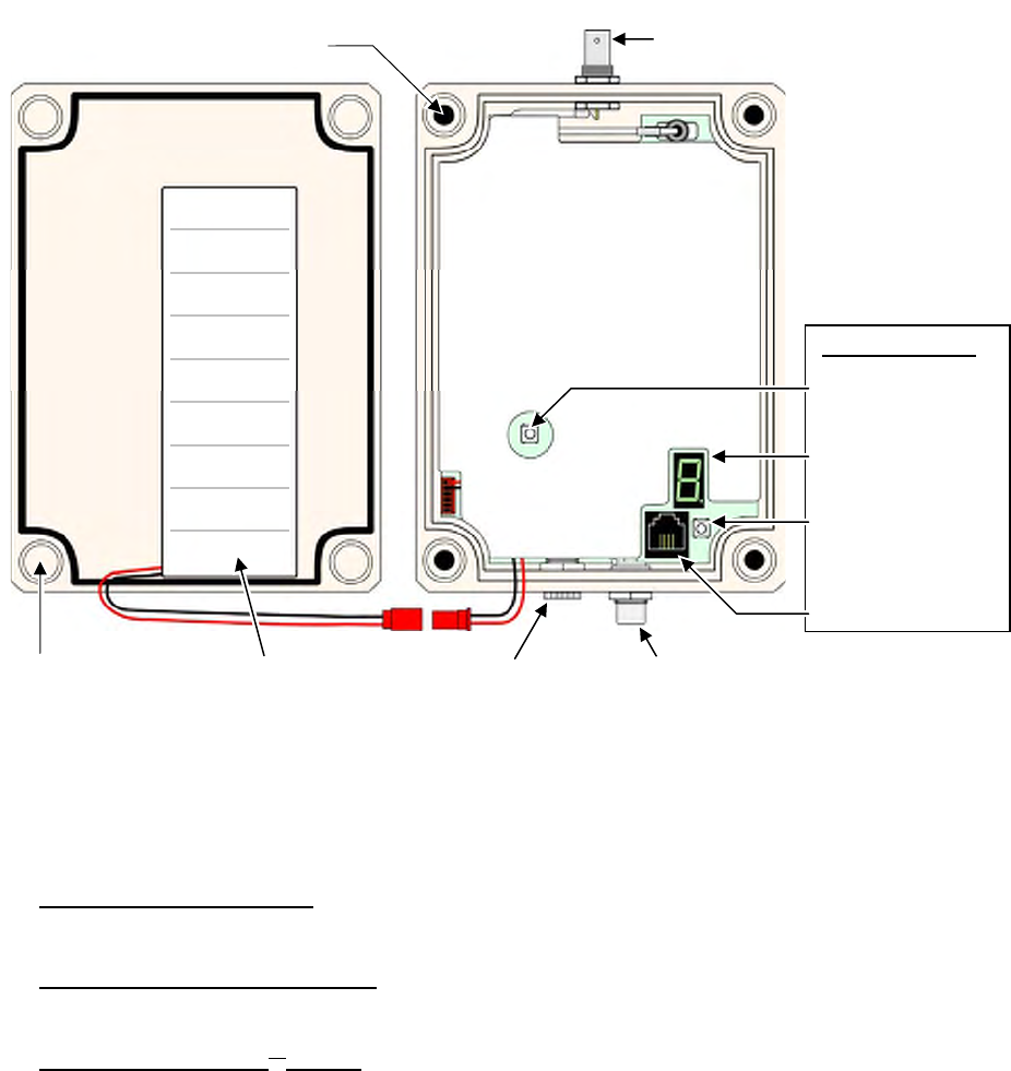
1.2 Loudmouth™ receiver assembly
The Loudmouth™ receiver and PA speaker is on any time power is applied to the receiver. For this reason the BP-
LM9 backup battery included with the Loudmouth™ is not connected when you receive it from the factory.
The Loudmouth™ receiver must be opened to connect the BP-LM9 battery, install the Mounting Bracket, or to
program the Loudmouth™.
Section 1 Getting Started 2
1. Loosen the (4) captive screws in the front corners of the case. These screws are captive to the housing; to
prevent damaging them, DO NOT remove the screws from the housing.
2. Separate the case front from the case back.
3. Install the Mounting Brackets by inserting the 4 sealed screws included in the Mounting Bracket kit into the
4 pre-drilled holes shown above. Secure the Mounting Brackets to the case using the lockwashers and nuts
included in the Mounting Bracket kit.
4. Connect the BP-LM9 backup battery to the Loudmouth™ receiver using the red mating connectors shown
above. The BP-LM9 is secured to the case front with interlocking mushroom-head fastener strips. Press firmly
on the battery to interlock the strips, snapping it into position.
5. Program the Loudmouth™ receiver per the instructions in the Programming section of this manual, leaving
the RPS-1A power supply or BP-LM9 backup battery connected to the radio. Press the Enter button twice
before re-assembling the case to be sure the Loudmouth™ is reset and ready for operation.
6. Carefully position the case front onto the case back. Secure the case halves by tightening the 4 captive
screws in the front corners of the case.
PROGRAMMING
Enter Button
Program Display
Program Button
RJ-11 Program
Cable Connector
DC Power Connecto
r
for RPS
-
1A
RCA Phono Jack for
S
p
eaker Connection
BP-LM9
Battery
Pre-drilled holes for Mounting
Bracket (4 corners) BNC Antenna Connector
for AFB
-
1545
Captive Plastic Case
Screws
(
4 corners
)

1.3 Paging the Loudmouth™ receiver and PA speaker
The Loudmouth™ receiver and PA speaker can be paged with 2-way radios programmed for Quiet Call (CTCSS),
Digital Quiet Call (DCS), 2-Tone Paging, or Selcall paging formats. Each format offers a unique method of paging
the Loudmouth™ receiver and PA speaker.
Refer to the Programming section of this manual for specific instructions on programming your Loudmouth™
receiver and PA speaker to one of these selective signaling formats.
Section 1 Getting Started 3
Ritron strongly recommends operation of the Loudmouth™ receiver and PA
speaker with one of the following selective signaling formats enabled.
Paging the Loudmouth™ with Quiet Call (CTCSS) only:
• To page the loudspeaker a user simply presses the 2-way radio’s PTT and speaks while on the
Loudmouth™ channel.
• Your 2-way radio must be programmed for a channel dedicated to Loudmouth™ operation. Only those
radios programmed with the Loudmouth™ channel will be able to access the loudspeaker.
• The 2-way radio’s Loudmouth™ channel and the Loudmouth™ receiver must be programmed for the
same QC code. All Ritron radios offer 50 different field-programmable QC codes from which to choose.
Paging the Loudmouth™ with Digital Quiet Call (DCS) only:
• To page the loudspeaker a user simply presses the 2-way radio’s PTT and speaks while on the
Loudmouth™ channel.
• Your 2-way radio must be programmed for a channel dedicated to Loudmouth™ operation. Only those
radios programmed with the Loudmouth™ channel will be able to access the loudspeaker.
• The 2-way radio’s Loudmouth™ channel and the Loudmouth™ receiver must be programmed for the
same DQC code. All Ritron radios offer 104 different field-programmable DQC codes from which to
choose.
Paging the Loudmouth™ with 2-Tone Paging:
• To page the Loudmouth™ the 2-way radio must first send the correct 2-Tone Paging code. Once
access to the loudspeaker is accomplished, the user simply presses the 2-way radio’s PTT and speaks
while on the Loudmouth™ channel. After a period of inactivity the Loudmouth™ is automatically reset,
and will then require the correct 2-Tone Paging code to re-gain access.
• Only 2-way radios programmed to send the correct 2-Tone code on the Loudmouth™ channel can
access the Loudmouth™ wireless PA speaker. However, once access is gained, any 2-way radio that
operates on the Loudmouth™ channel can access the loudspeaker up until the time that the
Loudmouth™ has automatically reset.
• Can be used in conjunction with QC or DQC for added security. The 2-way radio and the Loudmouth™
receiver must be programmed for the same QC or DQC code.
Paging the Loudmouth™ with Selcall:
• To page the Loudmouth™ the 2-way radio must be programmed to send the correct Selcall code every
time the PTT is pressed. The user simply presses the 2-way radio’s PTT and speaks while on the
Loudmouth™ channel.
• Only 2-way radios programmed to send the correct Selcall code on the Loudmouth™ channel can
access the Loudmouth™ wireless PA speaker.
• Can be used in conjunction with QC or DQC for added security. The 2-way radio and the Loudmouth™
receiver must be programmed for the same QC or DQC code.

Ritron recommends the use of a dedicated channel frequency for
Loudmouth™ operation.
When operating on unique frequencies dedicated to loudspeaker operation:
• Your 2-way radios must be programmed for a channel dedicated to loudspeaker operation.
• Loudspeaker operation is limited to radios programmed with the dedicated Loudmouth™ channel.
• The use of 2-tone or Selcall paging to address the Loudmouth™ is not required, but can still be used if
additional access security is desired.
• Without 2-tone or Selcall paging the loudspeaker can be addressed by simply selecting the
Loudmouth™ channel on your 2-way radio and pressing the PTT button to talk.
• You may need to license additional frequencies (not necessary with LM-V150 programmed for MURS
frequencies, see Table 1 in the Programming section).
When operating on your normal 2-way communication frequencies:
• Messages broadcast on the Loudmouth™ are also heard on your 2-way radios.
• Loudspeaker messages are not possible when the channel is being used for 2-way communications.
• The use of 2-tone or Selcall paging is required to address the Loudmouth™, otherwise all 2-way
communication is heard on the loud speaker.
• Any user on your 2-way channel can broadcast over the loudspeaker once it is activated, even if their
2-way radio is not programmed with the correct 2-tone paging code.
• There is no need to license additional frequencies.
Section 1 Getting Started 4
1.4 Compatibility with other RITRON model radios
The Loudmouth™ receiver and PA speaker is available in both VHF (LM-V150, 150-165 MHz) and UHF (LM-U450,
450-470 MHz) business band frequencies. Loudmouth™ can be accessed with radios programmed for Quiet Call
(CTCSS), Digital Quiet Call (DCS), 2-Tone Paging, or Selcall paging formats. The following chart can be used to
determine compatibility with existing Ritron radios.
VHF models compatible with LM-V150 UHF models compatible with LM-U450
2- 2-
Model Type QC DQC Tone Selcall Model Type QC DQC Tone Selcall
JMX-141D Portable √ JMX-441D Portable
√
JMX-144D Portable √ √ √ JMX-444D Portable
√ √ √
JMX-146D Portable √ JMX-446D Portable
√ √ √
JBS-146D Base √ √ √ JBS-446D Base √ √ √
* J-V110 Portable √ √ √ * J-U410 Portable
√ √ √
RPM-160 Mobile √ √ √ √ RPM-460 Mobile √ √ √ √
RQX-151 Callbox √ √ RQX-451 Callbox
√ √
RQX-156 Callbox √ √ √ RQX-456 Callbox √ √ √
RQX-157 Callbox √ √ √ RQX-457 Callbox √ √ √
SLX-100 Portable
√ √ √ √ SLX-400 Portable √ √ √ √
* 2-Tone paging available with Rev 6 Firmware Only. See label inside radio battery compartment for
firmware revision.
1.5 Determine the volume setting
Selecting the correct volume level is critical to the performance of the Loudmouth™ receiver and PA speaker.
Carefully consider the following before deciding on the appropriate volume setting. Refer to the Programming
section of this manual for specific instructions on programming the Volume Level.
Ambient (average) noise level should be considered first when selecting the
volume level.
Increasing the volume level in an effort to cover a wider area will result in:
• Undesirably high volume when near the speaker.
• Low volume at the outer edges of the coverage area.
• A calling radio must be a greater distance from the Loudmouth™ speaker to prevent feedback.
(Feedback is the result of Loudmouth™ speaker audio getting into the calling radio’s microphone.)
When coverage of a large area is required, additional Loudmouth™ speakers may be necessary for
satisfactory performance. See the Installation section of this manual for details on how to install 2 speakers
using a single Loudmouth™ receiver, or multiple receivers and speakers.
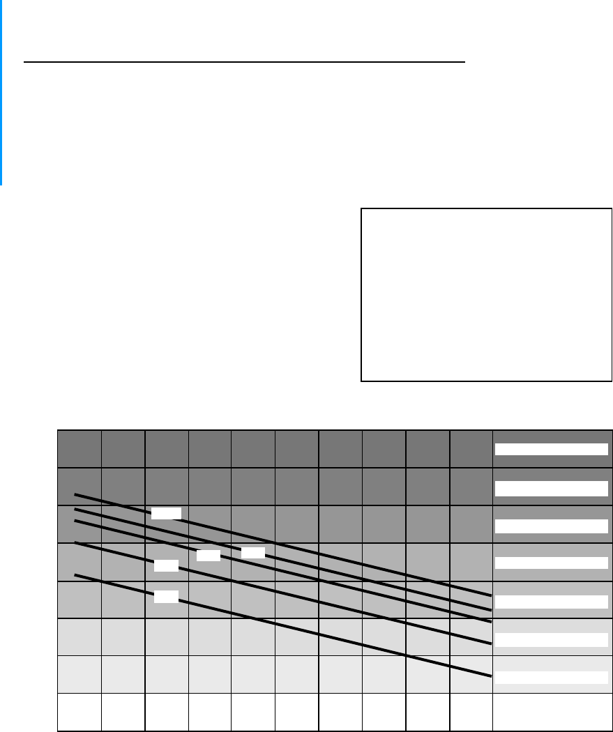
1. Refer to the horizontal shaded bars on the chart below to
determine the sound level that best represents your
location. This should be the ambient, or average sound
level. We will consider the maximum sound level when
we locate the speaker.
2. Estimate the maximum distance (in feet) that the
loudspeaker must be heard. Locate that distance on the
chart below and follow it up to find the line that is in the
middle of your shaded bar. This line indicates the
optimum Loudmouth™ volume level setting.
EXAMPLE: In the Ritron factory we
need to cover a maximum distance of 50
feet on the factory floor with an ambient
sound level similar to a warehouse. I
find the vertical line at the bottom of the
chart indicating 50 feet, and follow it up
to the shaded bar indicating Warehouse.
The 50% and 75% lines are in the middle
of the Warehouse bar, indicating a
required Loudmouth™ volume setting
between 50 - 75%.
Rock Music
Subway Train
Section 1 Getting Started 5
Loudmouth Volume
Industrial Factory
Warehouse
Bus
y
Restaurant
Lar
g
e Office
Hos
p
ital
Doctors Office
0 10 20 30 40 50 60 70 80 90 100
Distance (Feet)
120
110
100
90
80
70
60
50
40
100%
75%
50%
25%
SPL
(dB) 10%
Section 2 Installation 6
2 Installation
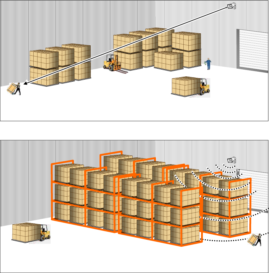
Proper installation of the Loudmouth™ wireless PA speaker is critical to the
performance and overall satisfaction with your system. With careful consideration
and planning Loudmouth™ will cover up to 100 feet with a single speaker, and can
cover an even wider range with multiple speakers and receivers. This section will
help you plan an installation that is best suited for your environment.
2.1 Selecting the PA speaker location
Speaker location is critical to the performance of the Loudmouth™ receiver and PA speaker. Consider the
following factors before selecting a speaker location.
• The speaker can be installed either indoors or outdoors.
• Be sure there is a convenient source of 110VAC power for the RPS-1A power cube and that the radio receiver
box can be located inside, out of the elements. The speaker has a 25 ft. cable, if you need more a standard
RCA phono cable and coupler can be used (ie. Radio Shack Catalog #: 42-2363 and Catalog #: 274-1553).
• The speaker should not be in an area where the 2-way radio user addressing the speaker will typically be
located. If the radio user is too close to the Loudmouth™ speaker, feedback can occur due to loudspeaker
audio getting into the radio microphone. This is a problem related to the 2-way radio, not the Loudmouth™
speaker. The use of the Record & Play feature will eliminate this problem.
The speaker must be located at least 10 feet above head level.
At near range the Loudmouth™ speaker is capable of sound levels that can cause
permanent hearing loss and should never be installed in a location where a person
could be directly in front of the speaker.
Install the Loudmouth
™
speaker close to the noisiest area you plan to cover.
If there is an area with a significantly higher ambient noise level, the Loudmouth™
speaker should be located as close as possible to this area. The speaker volume
must be 6 db higher than the ambient noise level in order to be heard.
If the speaker is not close to the highest source of noise, the
volume level will be too loud for the quieter areas.
Section 2 Installation 7
The Loudmouth
™
speaker should be mounted as high as practical and
pointed toward the farthest location you need to cover.
Large obstructions will significantly reduce the coverage area.
Do not place the speaker behind large, tall objects.
Section 2 Installation 8
2.2 PA Speaker installation
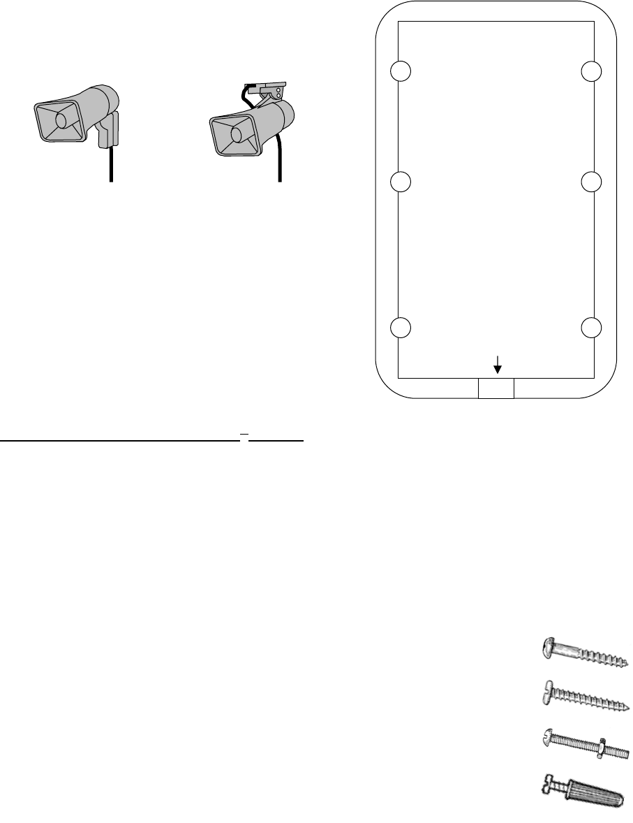
The speaker mount can be installed vertically on a wall,
flat post or support column; or can be mounted
horizontally from a ceiling or rafter beam. TOP / REAR
Speaker
Mounting
Template
Speaker
wire exit
REAR
Ceiling mounted
TOP
Wall mounted
Once the speaker location has been determined the
Speaker Mounting Template may be used to mark the
mounting surface. When using the Speaker Mounting
Template keep in mind that the speaker wire exit is toward
the floor on a wall mounted installation, and toward the
front of the speaker in a ceiling mounted installation.
The Loudmouth™ speaker may be secured to a variety of
surfaces, with each installation presenting unique
requirements for mounting hardware. With this in mind,
mounting screws or hardware are not included with the
Loudmouth™.
Guidelines for mounting the Loudmouth™ speaker:
• The Loudmouth™ speaker can be safely mounted to concrete, metal or wood surfaces. Other surfaces are
possible provided they can support the weight of the speaker. If mounting to a drywall or concrete surface
the use of expansion anchors is recommended.
• Secure the speaker tightly to the mounting surface, using all 6 mounting holes if possible. At high audio
output levels the speaker can generate significant vibration and must be rigidly secured. This is particularly
critical with drywall surfaces, which are highly susceptible to vibration damage.
• Be sure the speaker wire exits cleanly from under the speaker mounting bracket through the wire exit
tunnel provided. Pinching the speaker wires could cause a short that will destroy the Loudmouth™ receiver
audio amplifier.
• Route the speaker wire closely against a wall or support
beam. Speaker wire hanging in free space is easily
snagged and could be pulled from the Loudmouth™
receiver or worse yet, pulled from the speaker itself
causing permanent damage.
Wood Screw
Sheet Metal Screw
Machine Screw with Nut
Drywall Anchor and Screw
• 1 inch long, #8 or #10 round-head screws should be
used to mount the speaker. Wood screws, sheet metal
screws, machine screws with nuts, or drywall anchors
and screws will all work well depending on your specific
requirements. Pan-head screws should not be used to
prevent damage to the mounting bracket due to over-
tightening.
Section 2 Installation 9
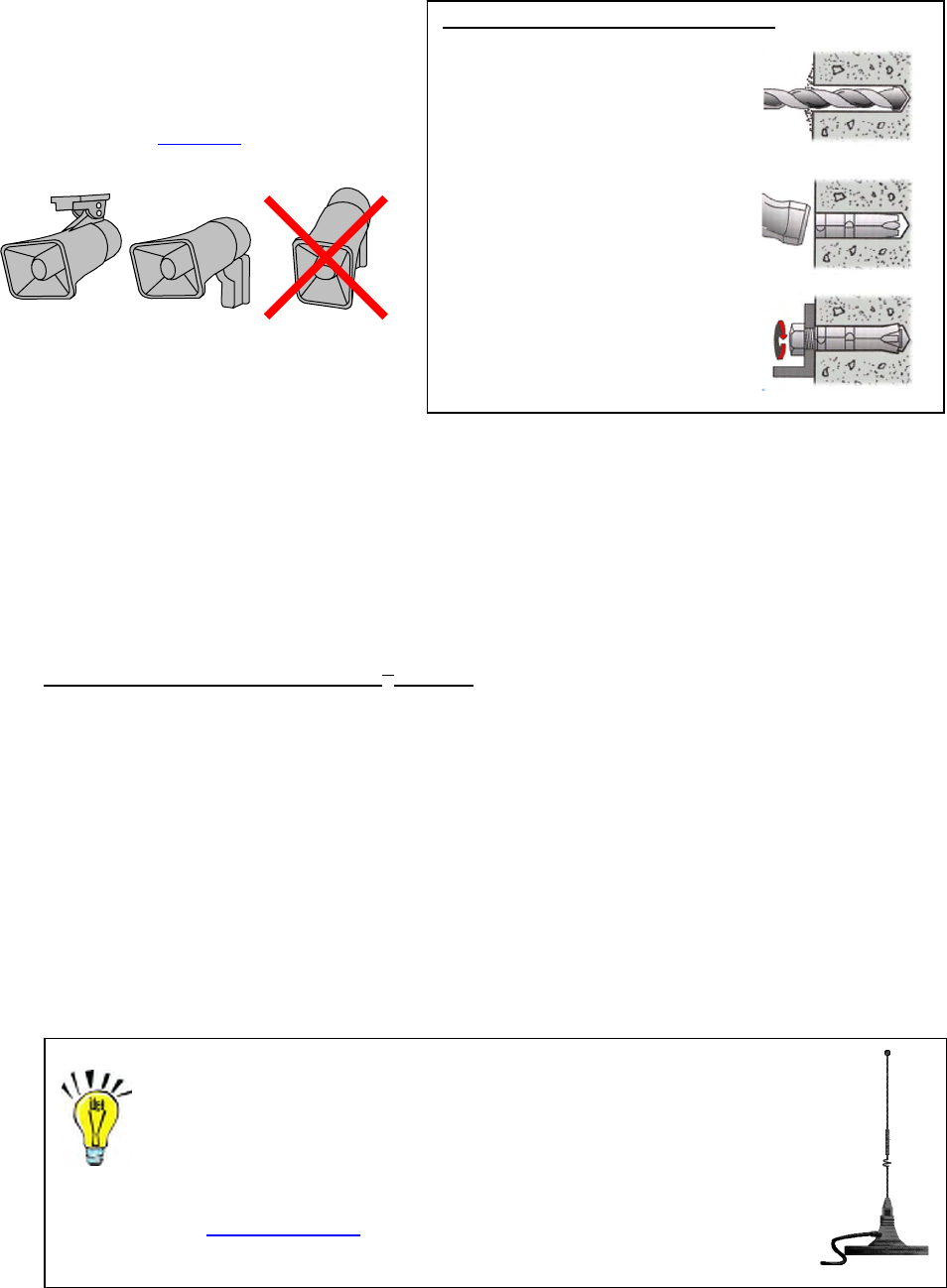
Installing Concrete Expansion Anchors
1. Drill hole of recommended
diameter, see chart below, into the
base material to a depth equal to,
or slightly deeper than the length
of the expansion shield. Clean out
the hole of all dust and cuttings.
2. Place the Single Expansion
anchor, nut end first, into the hole.
The top end of the anchor should
be flush or slightly below the base
material surface.
3. Place the object to be fastened
over the anchor in the base
material and bolt into place. The
bolt should engage 2/3 of the
threads of the anchor.
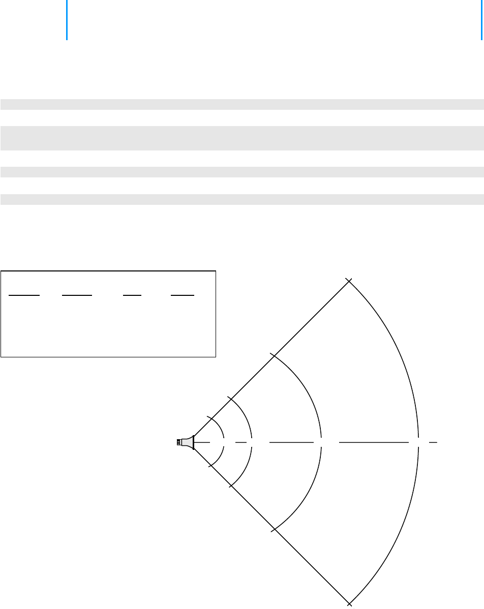
The Loudmouth™ speaker should be mounted
horizontally for the widest coverage
When mounted horizontally the Loudmouth™
speaker will provide 90° horizontal and 60°
vertical coverage without significant loss of sound
level. Refer to the SPL chart on page 25 for
typical sound levels at full volume.
2.3 Loudmouth™ radio receiver installation
Installation of the Loudmouth™ receiver is critical to the effective radio coverage of the radio loudspeaker system.
Without proper installation the maximum possible distance between the calling radio and the Loudmouth™
receiver will be significantly reduced.
Guidelines for installing the Loudmouth™ receiver:
• The radio receiver box must be located inside, out of the elements.
• Be sure there is a convenient source of 110VAC power for the RPS-1A power cube.
• The Loudmouth™ receiver should be installed in a central location and as high up as possible for best radio
coverage.
• For maximum radio coverage the antenna should be in a vertical orientation and should not be touching or
surrounded by large metal objects. The receiver box can be mounted horizontally as long as the antenna is
in a vertical position.
• Do not install the Loudmouth™ receiver in a high traffic location with the possibility that the receiver box
would be struck, become unplugged, or the speaker be disconnected.
• Do not wind, loop or otherwise allow the power cord from the RPS-1A power cube to contact the antenna.
The power cord should be routed away from the antenna.
Radio range can be extended with the use of an external
antenna.
The antenna can be installed at a higher elevation than is possible with the
attached antenna.
The Ritron RAM-1545 VHF/UHF magnet-mount antenna has a 25 ft.
cable to allow optimum antenna location.
Section 2 Installation 10
2.4 Installing two PA speakers with a single Loudmouth™ receiver
Many locations may require the installation of two speakers with a single Loudmouth™
receiver. Two speakers are used when: You can connect 2
speakers to a single
Loudmouth™ receiver
using an RCA phono
type Y-connector.
(i.e.Radio Shack
Catalog # 274-881)
• Coverage is required over a large area.
• Large obstructions limit the effective range of a single speaker.
• A wall separates two coverage areas.
• The ambient noise level is low and individual speaker volume must be reduced
(i.e. Hospital).
• The calling radio is in the area where the speakers are located and speaker
volume must be reduced to prevent feedback.
In some installations a single Loudmouth™ receiver can be used to drive two
speakers, while others will require a separate receiver for each speaker.
To cover a large area, or an area with large obstructions, place 2 speakers
back-to-back in a central location.
• The speakers should be mounted as high as possible and pointing away from each other.
• The 2 speakers can be driven by a single Loudmouth™ receiver.
• Volume level may be reduced compared to a single speaker, making the system less susceptible to
feedback.
Use 2 Speakers to reduce volume level
Surprisingly, the use of 2 speakers powered by a single
Loudmouth™ receiver can allow you to reduce the volume
level in a quiet environment.
By covering an area with 2 centrally located speakers,
installed back-to-back, the volume level can be cut in half.
Section 2 Installation 11
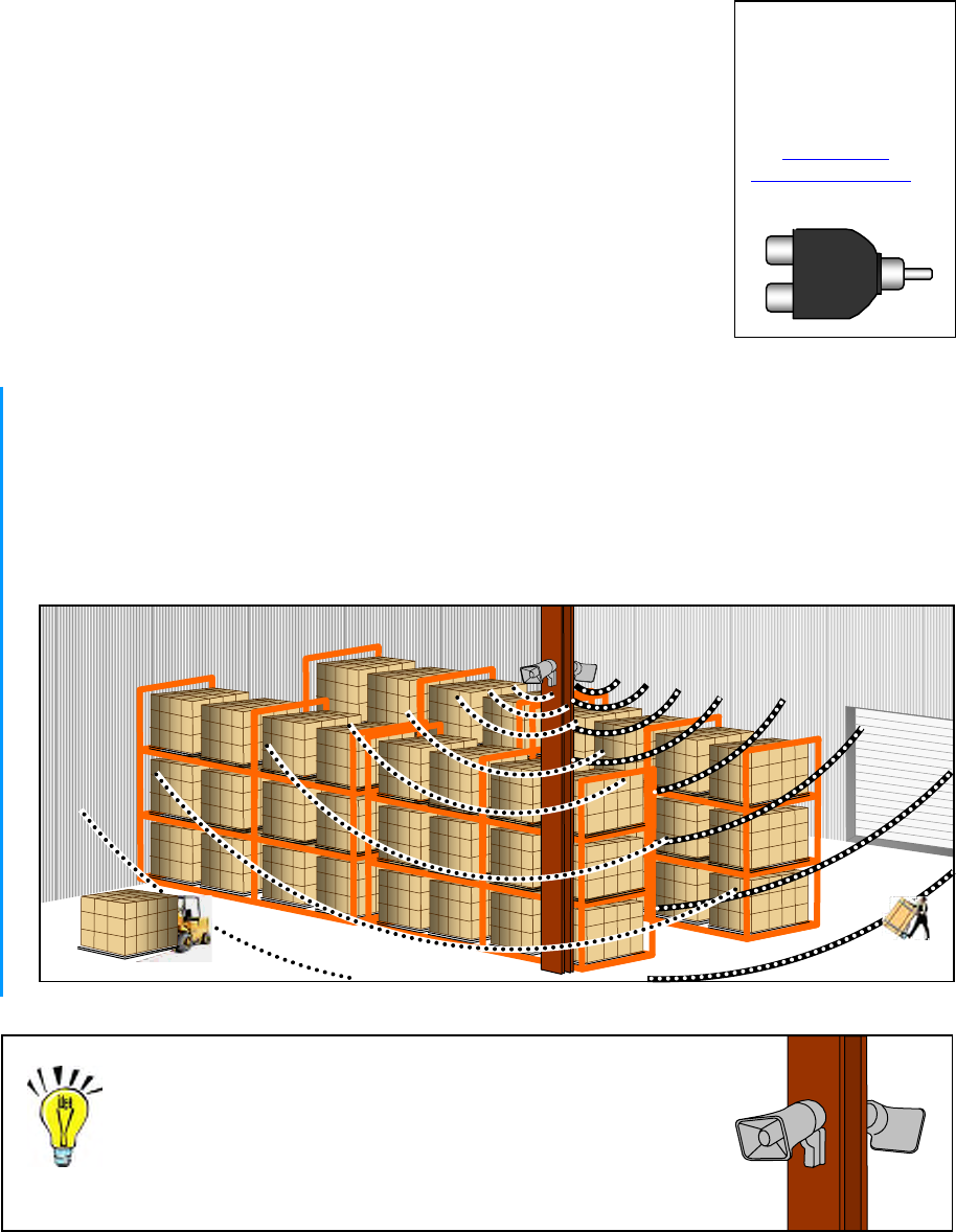
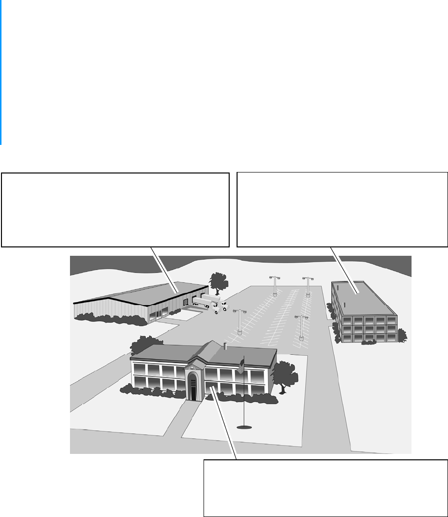
2.5 Installing multiple Loudmouth™ receivers and PA speakers
Many locations may require the installation of multiple Loudmouth™ receivers and PA speakers. Multiple receivers
and PA speakers are used when:
• Paging separate buildings is required.
• The coverage area is too large for a single receiver and PA speaker.
• Zone paging is required.
• Paging is required in more than one location.
Zone paging, or paging in more than one location requires a separate
Loudmouth™ receiver for each area.
• With zone paging all radios can operate on the same Loudmouth™ radio frequency.
• Each Loudmouth™ receiver can be programmed for a unique paging code, allowing selective paging to
each zone.
• The Loudmouth™ receivers can be programmed for an All Call* code that allows paging of all zones at
once, or Group Call* to page more than one zone.
• Zone paging allows for volume levels that are programmed to the specific needs of that area.
• If zone paging is not necessary, all Loudmouth™ receivers can be programmed for the same paging
code.
* All Call and Group Call code programming requires the Ritron Loudmouth™ PC Programmer.
Zone 2 – Cafeteria
• Single Loudmouth receiver with 1 speaker.
• The speaker is located inside the cafeteria area.
• Speaker volume is set to 25% for the restaurant
environment.
Zone 1 – Warehouse and loading dock
• Single Loudmouth receiver with 2 speakers.
• One speaker is located inside the warehouse and the
other is located outside for the loading dock.
• Speaker volume is set to 50% for the warehouse
environment.
Zone 3 – Sales office
• Single Loudmouth receiver with 1 speaker.
• The speaker is located inside the Sales office.
• Speaker volume is set to 10% for the office environment.
Example of Zone paging
Section 2 Installation 12
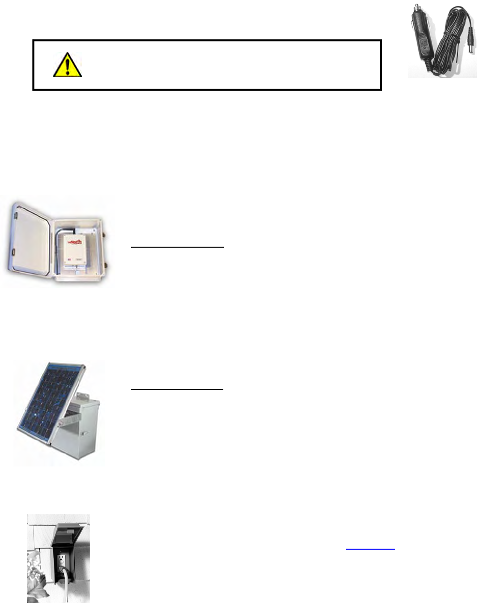
2.6 Vehicular installation
The Loudmouth™ receiver can be powered with an optional Ritron model CCL-M cigarette lighter adapter for use in
mobile applications.
• Route the CCL-M power cord away from the antenna and speaker wires.
When the speaker is mounted on the roof of a vehicle at head
level the volume level should be reduced to 50% or less to
prevent hearing damage. CCL-M
2.7 Temporary outdoor installation
The Loudmouth™ receiver can be temporarily installed outdoor with the use of weatherproof enclosures.
LMH-100
The Ritron model LMH-100 is a weatherproof, fiberglass reinforced polyester enclosure
designed to house the Loudmouth™ receiver and antenna. Speaker and power
connections are routed from the bottom of the enclosure through electrical conduit.
The LMH-100 includes:
• Dual stainless steel, padlockable latches
• Nema 3 weatherproof, fiberglass reinforced polyester enclosure
• Mounting flanges for flat surface
• Dimensions: 13”H x 10.5”W x 5.5”D Weight: 8 lbs.
Ritron model RSS-100 10W solar panel kit can be used to power the Loudmouth™
receiver without the need for the RPS-1A power supply in locations where AC power is
not available.
RSS-100
The RSS-100 includes:
• 10-Watt solar panel with mounting bracket
• 7AH sealed rechargeable battery
• Solar charge controller
• Nema 3 weatherproof, fiberglass enclosure
• Mounting flanges for flat surface
• Dimensions: 12”H x 10.25”W x 6.25”D Weight: 10 lbs.
E9UDV
The RPS-1A power cube can be temporarily plugged into an outdoor outlet with a large
in-use weatherproof cover such as the Carlon® model E9UDVCRN (available in Lowe’s
Hardware stores nationwide).
CRN
Section 3 Programming 13
3 Programming
For most installations the Loudmouth™ can be programmed in the field without the
need for Ritron PC Programmer 12.0.1. Field programming is accomplished in 3
easy steps. First, the radio frequency and tone codes are entered. Second, the
selective signaling code is entered (if used). Third, the Loudmouth™ options and
volume setting are entered.
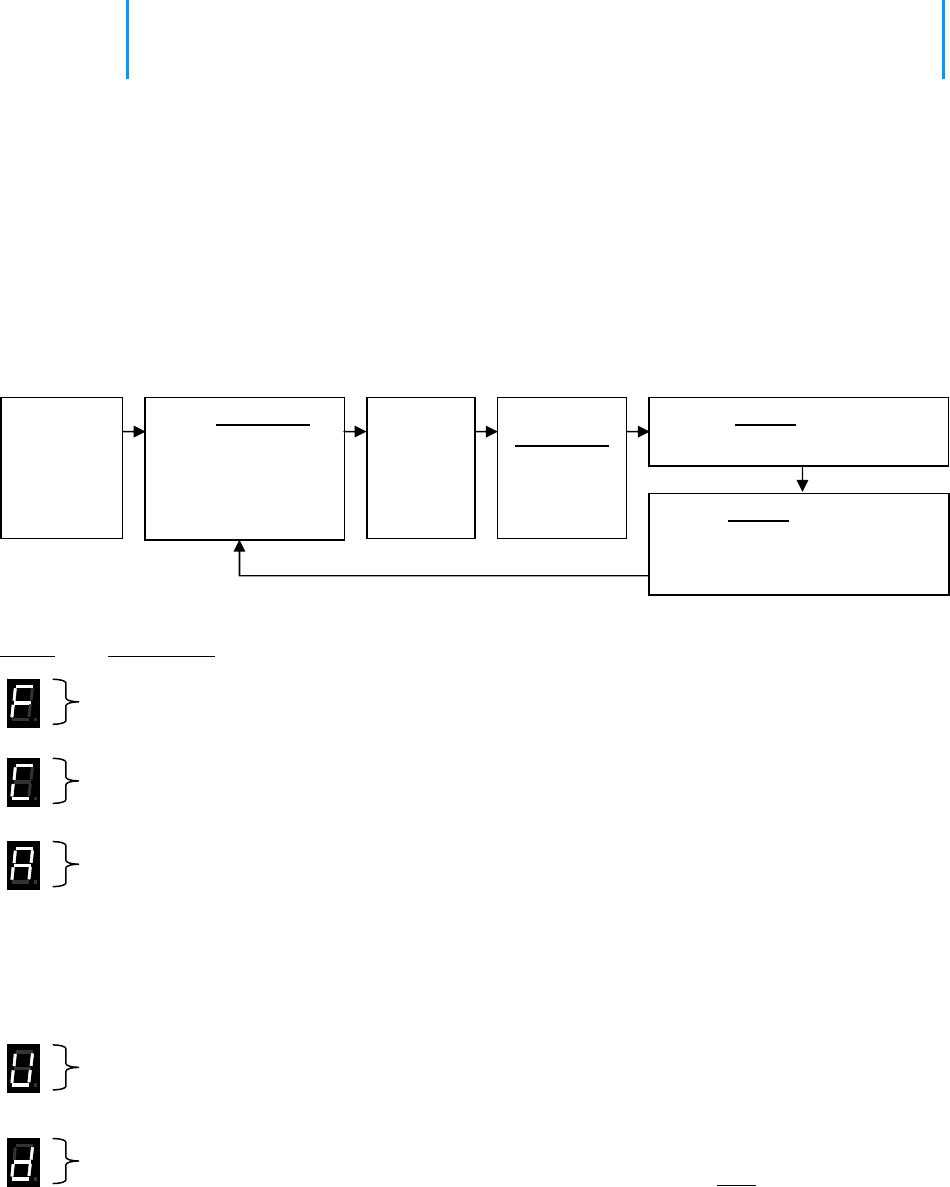
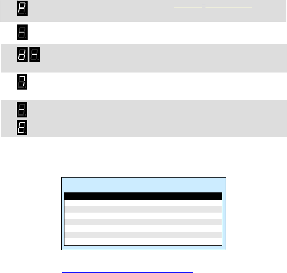
3.1 Loudmouth™ Field Programming Overview
Press ENTER
Program
odes
C Table Codes
Enter a 2-digit Frequency code from Table 1 and a 2-digit QC code from Table 2 or
nter a 2-digit Frequency code from Table 1 and a 3-digit DQC code from Table 3.
E
or
Enter a 2-digit, 2-Tone Paging code from Table 4
Enter any 3 – digit Selcall Paging Code. 7-
E r a ™
nte 2-digit Loudmouth Feature code from Table 5 to:
• Enable or disable a Pre-Announce Tone.
• Enable or disable Record and Play operation.
ly)
• Enable or disable Weather Alert feature (VHF models on
on.
• Enable or disable Battery Powered Operati
• Enable or Disable Power Save operation.
• Reset L udmouth to Factory default programming.
o
Enter the desired Speaker Volume Level as a 2 –digit number from 05 – 99.
Enter the 1-digit NOAA Weather Frequency code from Table 6 (VHF models only)
This only programs the NOAA weather frequency, the Weather Alert feature must be enabled using
the Special Features code in Table 5.
Place the
Loudmouth
receiver
into
Program
mode.
Use PROGRAM
button to scroll to
one of the following
Program Code
characters:
[F], [C], [A], [U], [d]
Pause, a
hyphen
will
appear
on the
display.
Using the
PROGRAM button to save
programming entry.
button,
enter the
desired
Table Code. Press ENTER button a second
time to Exit programming.
or
Proceed with next program entry.

Section 3 Programming 14
3.2 ignaling Codes Readout Current Frequency, Tone and Selective S
1. Loosen the (4) captive screws in the front corners of the case. These screws are captive to the housing; to
prevent damaging them, DO NOT remove the screws from the housing.
2. Separate the case front from the case back, leaving the RPS-1A power supply or backup battery connected to
the radio. NOTE: The voltage of the batteries must be greater than 6 VDC to program properly.
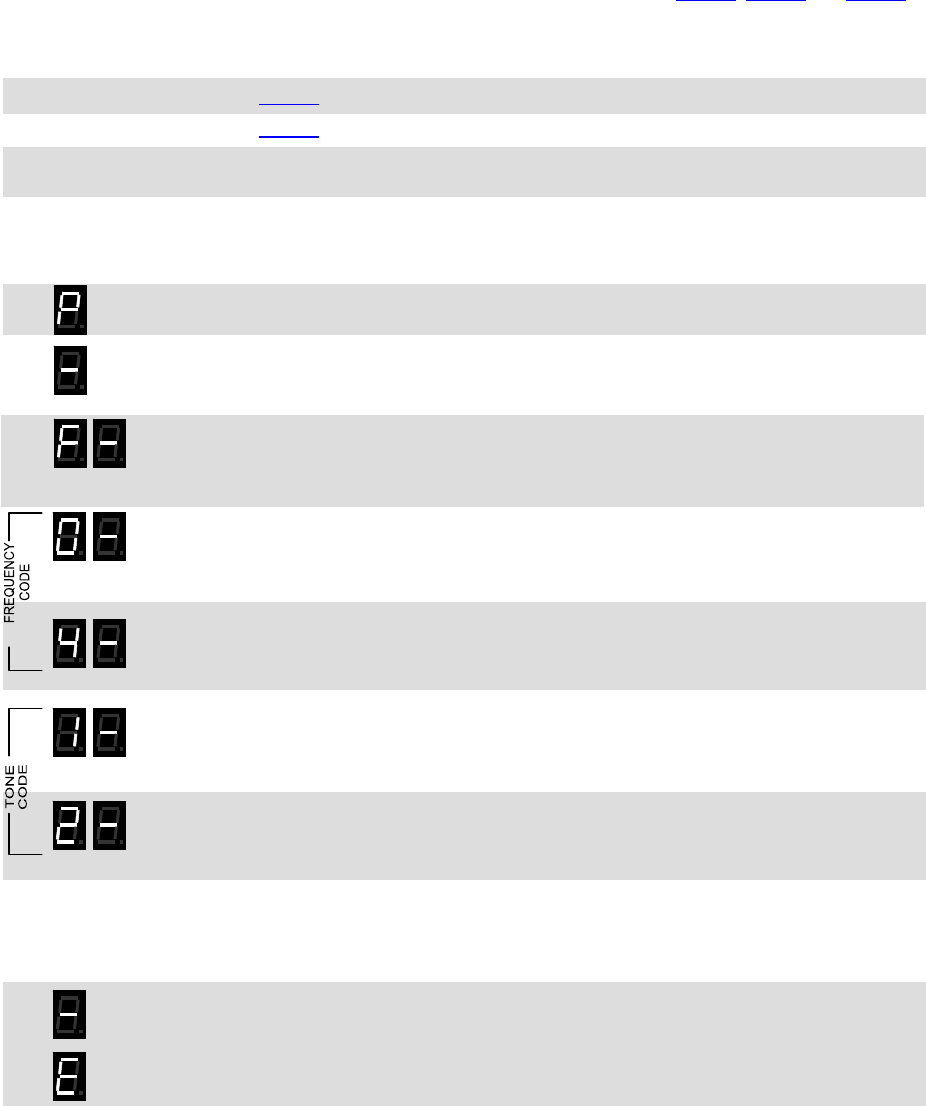
3. Press and release the PROGRAM button (See Loudmouth™ receiver assembly on page 2 for location). The
radio will immediately begin to display a series of digits; with each digit separated by a hyphen.
4. Write down the all the digits. The first two digits indicate the frequency code and the next two digits the tone
code; see Table 1 and Table 2 on page 16. In this example an LM-U450 is programmed to operate on the
“Brown Dot” frequency of 464.500 MHz (Frequency code “04”) with 100.0 Hz tone (Tone code “12”).
. If a 5th digit is displayed, the Loudmouth™ has been programmed for DQC and the last three digits indicate the
DQC code; see Table 3
FREQUENCY CODE TONE CODE
5 on page 16. In this example an LM-U450 was programmed to operate on the “Brown
Dot” frequency of 464.500 MHz (Frequency code “04”) with a DQC code of “723”.
6.
Tone paging code (see Table 4
If more than 5 digits are displayed, the radio has been programmed for Selective Signaling Decode. The
frequency and tone codes will be displayed, followed by a “C”, then the radio will display either the 2-digit, 2-
FREQUENCY CODE DQC CODE
on 16) or the 3-7 digit Selcall code. In this example an LM-U450 was
programmed to operate on the “Brown Dot” frequency of 464.500 MHz (Frequency code “04”) with 100.0 Hz
-Tone code “91”)
7. the Loudmouth is PC programmed with any frequency not listed in Table 1
tone (Tone code “12”) and 2-tone paging decode frequencies of 330.5 Hz and 569.1 Hz (2
™
If
FREQUENCY CODE TONE CODE PAGING CODE
on page 16, the radio will
ut the radios
frequency programming.
8. Normal radio operation resumes after the programming information has been displayed.
display a code "99" for the frequency code. The PC programmer will be required to reado
Section 3 Programming 15
3.3 Program Frequency & Tone Codes
To match other radios, the owner can select Frequency, Tone and DQC Codes from Table 1, Table 2 and Table 3.
In our example, we will program an LM-U450 to operate on the "Brown Dot" frequency of 464.500 MHz with 100.0
Hz tone.
04
12
1. Refer to
Table 1 to determine the two-digit frequency code and write it down.
2. Refer to
Table 2 to determine the two-digit tone code for 100.0 Hz and write it down.
3. Loosen the (4) captive screws in the front corners of the case. These screws are captive to
the housing; to prevent damaging them, DO NOT remove the screws from the housing.
4. Separate the case front from the case back, leaving the RPS-1A power supply or backup
battery connected to the radio.
NOTE: The voltage of the batteries must be greater than 6 VDC to program properly.
5. Press and HOLD the PROGRAM button. A "P" will appear on the program display as you
enter program mode and the radio will beep rapidly.
6. Release the PROGRAM button after the beeping has stopped. The radio will emit a triple
beep indicating that the radio is in program mode and a hyphen will appear on the program
display.
7. Scroll to the character “F” by clicking the PROGRAM button until the program display
shows the correct character. Pause—the radio will sound a low tone and show a hyphen
across the center of the display to indicate that it is ready to accept the first digit of the
frequency code.
8. Enter the 1st digit of the frequency code by clicking the PROGRAM button until the
program display shows the desired number. Pause—the radio will sound a low tone and
show a hyphen across the center of the display to indicate that it is ready to accept the
next digit.
9. Enter the 2nd digit of the frequency code by clicking the PROGRAM button until the
program display shows the desired number. Pause—the radio sounds a low tone and will
show a hyphen across the center of the display to indicate that it is ready to accept the
next digit.
10. Enter the 1st digit of the tone code (or 1st digit of the DQC code) by clicking the PROGRAM
button until the program display shows the desired number. Pause—the radio sounds a
low tone and will show a hyphen across the center of the display to indicate that it is ready
to accept the next digit.
11. Enter the 2nd digit of the tone code (or 2nd digit of the DQC code) by clicking the
PROGRAM button until the program display shows the desired number. Pause—the radio
sounds a low tone and will show a hyphen across the center of the display to indicate that
it is ready to accept the next digit.
12. FOR DQC CODES ONLY – Enter the 3rd digit of the DQC code by clicking the PROGRAM
button until the program display shows the desired number. Pause—the radio sounds a
low tone and will show a hyphen across the center of the display to indicate that it is ready
to accept the next digit.
13. Press and release the ENTER button to save your programming. A triple beep will sound to
indicate that programming was successful and a hyphen will appear on the program
display. The radio is now ready for another program entry.
NOTE: An error tone will sound if you attempt to save an incorrect code, an "E" will appear
on the display. Check the digits you are attempting to enter, then re-enter.
14. Once you have made your final program entry, press the ENTER button a final time to exit
programming mode. The Program display will be blank and the radio will be ready for use.
The Loudmouth™ will exit program mode automatically after 30 seconds if no program
entries are attempted.

Section 3 Programming 16
Table 2: Interference Eliminator Programmable QC Tone Codes
Table 3: Digital Interference Eliminator Programmable DQC Tone Codes
Table 1: Programmable Frequency Codes
VHF Business Band
Code Frequency Color Dot BW
03 151.625 Red Dot 25
04 151.955 Purple Dot 25
05 151.925 25
06 154.540 25
07 154.515 25
08 154.655 25
10 151.715 25
09 151.685 25
11 151.775 25
12 151.805 25
13 151.835 25
14 151.895 25
15 154.490 25
16 151.655 25
17 151.745 25
18 151.865 25
24 151.700 12.5
25 151.760 12.5
26 152.700 25
99 Custom programmed ---
VHF MURS**
01 154.600 Green Dot 25
02 154.570 Blue Dot 25
19 151.820 MURS 12.5
20 151.880 MURS 12.5
21 151.940 MURS 12.5
22 154.600 MURS 12.5
23 154.570 MURS 12.5
UHF Business Band
Code Frequency Color Dot BW
01 467.7625 J 25
02 467.8125 K 25
03 464.5500 Yellow Dot 25
04 464.5000 Brown Dot 25
05 467.8500 Silver Star 25
06 467.8750 Gold Star 25
07 467.9000 Red Star 25
08 467.9250 Blue Star 25
09 469.2625 25
10 462.5750 White Dot 25
11 462.6250 Black Dot 25
12 462.6750 Orange Dot 25
13 464.3250 25
14 464.8250 25
15 469.5000 25
16 469.5500 25
17 463.2625 25
18 464.9125 25
19 464.6000 25
20 464.7000 25
21 462.7250 25
22 464.5000 12.5
23 464.5500 12.5
24 467.7625 12.5
25 467.8125 12.5
26 467.8500 12.5
27 467.8750 12.5
28 467.9000 12.5
29 467.9250 12.5
30 461.0375 12.5
31 461.0625 12.5
UHF Business Band
Code Frequency Color Dot BW
32 461.0875 12.5
33 461.1125 12.5
34 461.1375 12.5
35 461.1625 12.5
36 461.1875 12.5
37 461.2125 12.5
38 461.2375 12.5
39 461.2625 12.5
40 461.2875 12.5
41 461.3125 12.5
42 461.3375 12.5
43 461.3625 12.5
44 462.7625 12.5
45 462.7875 12.5
46 462.8125 12.5
47 462.8375 12.5
48 462.8625 12.5
49 462.8875 12.5
50 462.9125 12.5
51 464.4875 12.5
52 464.5125 12.5
53 464.5375 12.5
54 464.5625 12.5
55 466.0375 12.5
56 466.0625 12.5
57 466.0875 12.5
58 466.1125 12.5
59 466.1375 12.5
60 466.1625 12.5
61 466.1875 12.5
62 466.2125 12.5
UHF Business Band
Code Frequency Color Dot BW
63 466.2375 12.5
64 466.2625 12.5
65 466.2875 12.5
66 466.3125 12.5
67 466.3375 12.5
68 466.3625 12.5
69 467.7875 12.5
70 467.8375 12.5
71 467.8625 12.5
72 467.8875 12.5
73 467.9125 12.5
74 469.4875 12.5
75 469.5125 12.5
76 469.5375 12.5
77 469.5625 12.5
99 Custom programmed ----
Canadian Models
UHF Canada
01 458.6625 25
02 469.2625 25
VHF Canada
01 151.055 25
02 151.115 25
British Columbia
01 154.100 25
02 158.940 25
Notes: ** MURS frequencies do not require an FCC license. All other frequencies require an FCC license.
• BW is the bandwidth in kHz. 12.5 kHz = narrow band channel, 25 kHz = wide band channel.
Code Frequency
01 67.0
02 71.9
03 74.4
04 77.0
05 79.7
06 82.5
07 85.4
08 88.5
09 91.5
Code Frequency
10 94.8
11 97.4
12 100.0
13 103.5
14 107.2
15 110.9
16 114.8
17 118.8
18 123.0
Code Frequency
19 127.3
20 131.8
21 136.5
22 141.3
23 146.2
24 151.4
25 156.7
26 162.2
27 167.9
Code Frequency
28 173.8
29 179.9
30 186.2
31 192.8
32 203.5
33 210.7
34 218.1
35 225.7
36 233.6
Code Frequency
37 241.8
38 250.3
39 69.4
40 159.8
41 165.5
42 171.3
43 177.3
44 No Tone
45 183.5
Code Frequency
46 189.9
47 196.6
48 199.5
49 206.5
50 229.1
51 254.1
00 No Tone
Code
023
025
026
031
032
036
043
047
051
053
054
Code
065
071
072
073
074
114
115
116
122
125
131
Code
132
134
143
145
152
155
156
162
165
172
174
Code
205
212
223
225
226
243
244
245
246
251
252
Code
255
261
263
265
266
271
274
306
311
315
325
Code
331
332
343
346
351
356
364
365
371
411
412
Code
413
423
431
432
445
446
452
454
455
462
464
Code
465
466
503
506
516
523
532
546
565
606
662
Code
612
624
627
631
632
645
654
664
703
712
723
Code
731
732
734
743
754
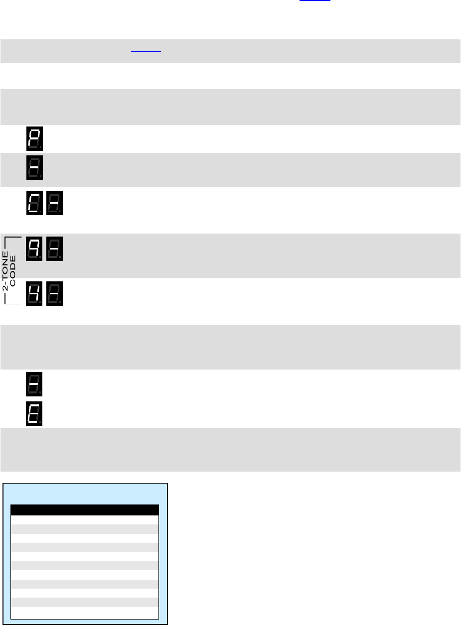
3.4 Program Paging Codes
For paging, it is desirable to program the wireless speaker for 2-Tone or Selcall operation. The user is able to field
program the radio for one of the 9 pre-determined 2-tone pairs specified in Table 4, or for a 3-7 digit Selcall code.
2-Tone codes correspond to field programmable 2-Tone encode (transmit) codes available in other RITRON
portable and base radios. In our example we will program an LM-U450 to operate with 2-Tone Paging Code 94
frequencies of 389.0 and 669.9 Hz.
94 1. Refer to
Table 4 to determine the two-digit code for 2-tone decode on 389.0 and 669.9 Hz
and write it down.
2. Loosen the (4) captive screws in the front corners of the case. These screws are captive to
the housing; to prevent damaging them, DO NOT remove the screws from the housing.
3. Separate the case front from the case back, leaving the RPS-1A power supply or backup
battery connected to the radio.
NOTE: The voltage of the batteries must be greater than 6 VDC to program properly.
4. Press and HOLD the PROGRAM button. A "P" will appear on the program display as you
enter program mode and the radio will beep rapidly.
5. Release the PROGRAM button after the beeping has stopped. The radio will emit a triple
beep indicating that the radio is in program mode and a hyphen will appear on the program
display.
6. Scroll to the character “C” by clicking the PROGRAM button until the program display
shows the correct character. Pause—the radio will sound a low tone and show a hyphen
across the center of the display to indicate that it is ready to accept the first digit of the 2-
Tone or Selcall code.
7. Enter the 1st digit of the 2-Tone or Selcall code by clicking the PROGRAM button until the
program display shows the desired number. Pause—the radio will sound a low tone and
show a hyphen across the center of the display to indicate that it is ready to accept the
next digit.
8. Enter the 2nd digit of the 2-Tone or Selcall code by clicking the PROGRAM button until the
program display shows the desired number. Pause—the radio sounds a low tone and
show a hyphen across the center of the display to indicate that it is ready to accept the
next digit.
9. FOR SELCALL CODES ONLY – Enter the 3rd, 4th, 5th, 6th, and 7th digits of the Selcall code
by clicking the PROGRAM button until the program display shows the desired number.
Pause—the radio sounds a low tone and will show a hyphen across the center of the
display to indicate that it is ready to accept the next digit.
10. Press and release the ENTER button to save your programming. A triple beep will sound to
indicate that programming was successful and a hyphen will appear on the program
display. The radio is now ready for another program entry.
NOTE: An error tone will sound if you attempt to save an incorrect code, an "E" will appear
on the display. Check the digits you are attempting to enter, then re-enter.
11. Once you have made your final program entry, press the ENTER button a final time to exit
programming mode. The Program display will be blank and the radio will be ready for use.
The Loudmouth™ will exit program mode automatically after 30 seconds if no program
entries are attempted.
Section 3 Programming 17
Table 4: 2-Tone Paging Codes
Code Tone 1 Tone 2
90 * *
91 330.5 569.1
92 349.0 600.9
93 368.5 634.5
94 389.0 669.9
95 410.8 707.3
96 433.7 746.8
97 457.9 788.5
98 483.5 832.5
99 330.5 600.9
00 No Selective Signaling
IMPORTANT NOTE:
* If the Loudmouth™ displays 2-Tone Paging Code “90” on
readout, it has been PC programmed for custom 2-Tone
frequencies. Entering code “90” will cause the Loudmouth™ to
operate on the PC programmed custom 2-Tone frequencies.
Section 3 Programming 18
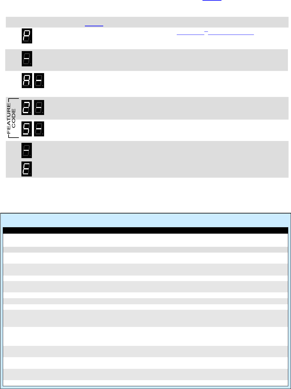
3.5 Program Loudmouth™ Features
The wireless speaker can be field programmed for a variety of features. Refer to Table 5 for the two digit codes
available for field programming. In our example we will program an LM-U450 for Record and Play operation. The
Loudmouth™ is set from the factory with these √ options enabled.
13 1. Refer to
Table 5 to determine the two-digit feature code and write it down.
2. Press and HOLD the PROGRAM button (See Loudmouth™ receiver assembly on page 2
for location). A "P" will appear on the program display as you enter program mode and the
radio will beep rapidly.
3. Release the PROGRAM button after the beeping has stopped. The radio will emit a triple
beep indicating that the radio is in program mode and a hyphen will appear on the program
display.
4. Scroll to the character “A” by clicking the PROGRAM button until the program display
shows the correct character. Pause—the radio will sound a low tone and show a hyphen
across the center of the display to indicate that it is ready to accept the first digit of the
Feature code.
5. Enter the 1st digit of the feature code by clicking the PROGRAM button until the program
display shows the desired number. Pause—the radio will sound a low tone and show a
hyphen across the center of the display to indicate that it is ready to accept the next digit.
6. Enter the 2nd digit of the feature code by clicking the PROGRAM button until the program
display shows the desired number. Pause—the radio sounds a low tone and will show a
hyphen across the center of the display to indicate that it is ready to accept the next digit.
7. Press and release the ENTER button to save your programming. A triple beep will sound to
indicate that programming was successful and a hyphen will appear on the program
display. The radio is now ready for another program entry.
NOTE: An error tone will sound if you attempt to save an incorrect code, an "E" will appear
on the display. Check the digits you are attempting to enter, then re-enter.
8. Once you have made your final program entry, press the ENTER button a final time to exit
programming mode. The Program display will be blank and the radio will be ready for use.
The Loudmouth™ will exit program mode automatically after 30 seconds if no program
entries are attempted.
Table 5: Loudmouth™ Feature Codes
Code Feature Default Description
Special Features
21 Reset to Factory Defaults Resets Wireless Speaker to Factory default programming.
22 Display Radio Revision Loudmouth™ will display a sequence of 6 digits to identify operating code
revision. This is helpful when troubleshooting the radio.
23 Pre-Announce Tone – On √ Enable this feature to play a short tone over the Loudmouth™ speaker
whenever it receives a signal.
24 Pre-Announce Tone – Off Disable Pre-Announce Tone
25 Record and Play – On When set received messages are recorded and played back over the
Loudmouth™ speaker immediately after the received signal is removed.
26 Record and Play – Off √ Disable Record and Play feature
27 One Speaker √ Set when one speaker is used for maximum available volume.
28 Two Speakers Set when two speakers are used for maximum available volume.
29 Weather Alert – On Enable this feature to receive local NOAA weather radio emergerncy
broadcasts from the National Weather Service and play them over the
Loudmouth™ speaker. This feature is only available on the LM-V150.
20 Weather Alert – Off √ Disable Weather Alert
Battery Powered Operation
41 Battery Operation – On Set to extend battery life when powering the Loudmouth™ with an external
battery.
42 Battery Operation - Off √ Set when powering the Loudmouth with the RPS-1A or an external DC
supply.
43 Power Save – On Set to enable Power Save operation for battery powered Loudmouth. This
option will have no effect unless Battery Operation – On is set.
44 Power Save – Off √ Set to disable Power Save operation for RPS-1A powered Loudmouth.
Section 3 Programming 19
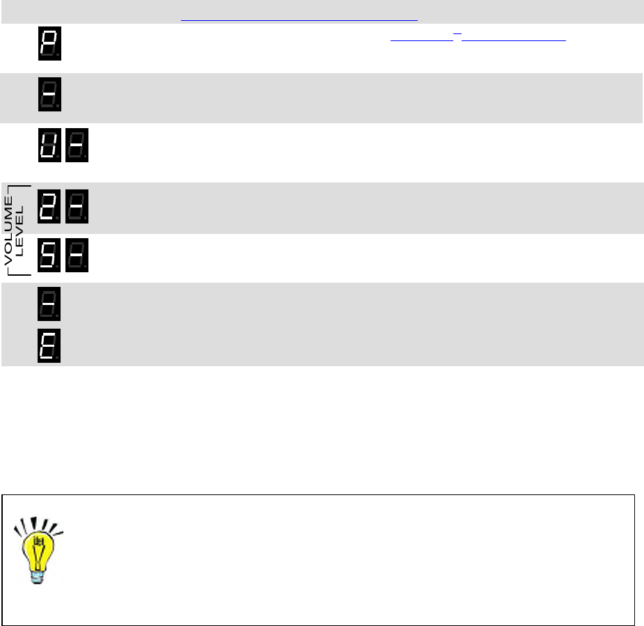
3.6 Program Loudmouth™ Volume
The wireless speaker can be field programmed for any volume level between 05-99% by entering the volume level
as a 2-digit code. Field programming Speaker Volume Level sets both the voice and the pre-announce tone
volume levels. The PC programmer is required for independent programming of the voice and the pre-announce
tone volume.
In our example we will program an LM-U450 for 25% Speaker Volume Level. The Loudmouth™ is set from the
factory with a 50% volume setting.
13 1. Refer to
Section 1.5 - Determine the volume setting and write down the desired volume.
2. Press and HOLD the PROGRAM button (See Loudmouth™ receiver assembly on page 2
for location). A "P" will appear on the program display as you enter program mode and the
radio will beep rapidly.
3. Release the PROGRAM button after the beeping has stopped. The radio will emit a triple
beep indicating that the radio is in program mode and a hyphen will appear on the program
display.
4. Scroll to the character “U” by clicking the PROGRAM button until the program display
shows the correct character. Pause—the radio will sound a low tone and show a hyphen
across the center of the display to indicate that it is ready to accept the first digit of the
volume setting.
5. Enter the 1st digit of the volume setting by clicking the PROGRAM button until the program
display shows the desired number. Pause—the radio will sound a low tone and show a
hyphen across the center of the display to indicate that it is ready to accept the next digit.
6. Enter the 2nd digit of the volume setting by clicking the PROGRAM button until the program
display shows the desired number. Pause—the radio sounds a low tone and will show a
hyphen across the center of the display to indicate that it is ready to accept the next digit.
7. Press and release the ENTER button to save your programming. A triple beep will sound to
indicate that programming was successful and a hyphen will appear on the program
display. The radio is now ready for another program entry.
NOTE: An error tone will sound if you attempt to save an incorrect code, an "E" will appear
on the display. Check the digits you are attempting to enter, then re-enter.
7. Once you have made your final program entry, press the ENTER button a final time to exit
programming mode. The Program display will be blank and the radio will be ready for use.
The Loudmouth™ will exit program mode automatically after 30 seconds if no program
entries are attempted.
IMPORTANT NOTE: Volume setting below 10% are entered as a 2-digit code with a first digit “0”.
Checking the Current Volume Setting
To readout the current volume setting, follow the instructions above and enter a
volume setting code “00”. When you press the ENTER button the radio will
immediately begin to display the 2-digit volume setting; with each digit separated by
a hyphen.
Section 3 Programming 20
3.7 Program the NOAA Weather Frequency
The LM-V150 can be programmed to play severe weather warnings originating from the National Weather service
that are broadcast on one of seven NOAA weather frequencies. The Loudmouth™ is shipped from the factory
without a NOAA weather frequency selected. Before the Weather Alert feature can be used you must first select
the local NOAA frequency.
1. Press and HOLD the PROGRAM button (See Loudmouth™ receiver assembly on page 2
for location). A "P" will appear on the program display as you enter program mode and the
radio will beep rapidly.
2. Release the PROGRAM button after the beeping has stopped. The radio will emit a triple
beep indicating that the radio is in program mode and a hyphen will appear on the program
display.
3. Scroll to the character “d” by clicking the PROGRAM button until the program display
shows the correct character. Pause—the radio will sound a low tone and show a hyphen
across the center of the display to indicate that it is ready to accept the NOAA Weather
Frequency code.
4. Enter the Weather Frequency code by clicking the PROGRAM button until the program
display shows the desired number. Pause—the radio sounds a low tone and will begin
playing the NOAA weather broadcast over the Loudmouth™ speaker. Monitor the channel
for a few minutes to be sure it is the broadcast for your local area.
5. Press and release the ENTER button to save your programming. A triple beep will sound to
indicate that programming was successful and a hyphen will appear on the program
display. The radio is now ready for another program entry.
NOTE: An error tone will sound if you attempt to save an incorrect code, an "E" will appear
on the display. Check the digits you are attempting to enter, then re-enter.
6. Once you have made your final program entry, press the ENTER button a final time to exit
programming mode. The Program display will be blank and the radio will be ready for use.
The Loudmouth™ will exit program mode automatically after 30 seconds if no program
entries are attempted.
Table 6: NOAA Weather Frequency Codes
Code Frequency
1 162.400 MHz
2 162.425 MHz
3 162.450 MHz
4 162.475 MHz
5 162.500 MHz
6 162.525 MHz
7 162.550 MHz
A complete list of NOAA weather frequencies available in your area can be found at
http://www.weather.gov/nwr/nwrbro.htm

4 Operation
Once installed, operating the Loudmouth™ radio receiver requires no human
contact. Portable, base station or mobile 2-way radios can deliver voice messages
directly to a PA speaker with a simple press of the PTT button for either live or
recorded playback. This section describes the subtle differences in operation for
various Loudmouth™ options and installations.
4.1 Basic Operation
Basic operation is defined as a Loudmouth™ receiver programmed on a dedicated radio frequency with a QC or
DQC code. The receiver is also programmed for 50% vol me and a pre-announce tone.
u
™
1. Move to an area that is away from the Loudmouth speaker to prevent feedback.
outh
2. Be sure the microphone on the calling radio is pointed away from the Loudm
™
™ speaker.
3. Set the portable, base station, or mobile radio to the Loudmouth channel.
4. Monitor the channel before transmitting to be sure there are no other radio users on the Loudmouth™
frequency.
5. Press and hold the PTT button and pause for about 1 second, allowing the pre-announce tone to be heard.
6. Speak into the radio microphone to broadcast your message over the Loudmouth™ speaker. If other radios
™ar your message.
are operating on the Loudmouth channel they will also he
7. Release the PTT button when your message is complete.
8. Return the portable, base station, or mobile radio to the normal operating channel.
Section 4 Operation 21
4.2 Selcall Paging
el.
nd the correct Selcall code on the Loudmouth™ channel can access the
Lo
outh™ speaker.
g to be sure there are no other radio users on the Loudmouth™
7. uth™ speaker. If other radios
ar your message.
9. Return the portable, base station, or mobile radio to the normal operating channel.
th
To access the Loudmouth™ the 2-way radio must be programmed to send the correct Selcall code every time the
PTT is pressed. The user simply presses the 2-way radio’s PTT and speaks while on the Loudmouth™ chann
Only 2-way radios programmed to se
udmouth™ wireless PA speaker.
1. Move to an area that is away from the Loudmouth™ speaker to prevent feedback.
2. Be sure the microphone on the calling radio is pointed away from the Loudm
3. Set the portable, base station, or mobile radio to the Loudmouth™ channel.
Monitor the 4. channel before transmittin
frequency.
5. Press and hold the PTT button.
6. Wait until the entire Selcall code has been sent, and then an additional 1 second for the pre-announce tone.
Speak into the radio microphone to broadcast your message over the Loudmo
are operating on the Loudmouth™ channel they will also he
8. Release the PTT button when your message is complete.
Wi Selcall Paging operation:
Selcall paging can be used in conjunction with QC or DQC for added security
• . The 2-way radio and the
Loudmouth™ receiver must be programmed for the same QC or DQC code.

Section 4 Operation 22
4.
t first send the correct 2-Tone Paging code. Once access to the
lo hile on the
Lo en require the
co c
4. fore transmitting to be sure there are no other radio users on the Loudmouth
nd, allowing the pre-announce tone to be heard.
h
10. If the radio PTT is pressed again before the Loudmouth receiver has reset, the message will be heard on
aging code.
11.
th
3 2-Tone Paging
To access the Loudmouth™ the 2-way radio mus
udspeaker is accomplished, the user simply presses the 2-way radio’s PTT and speaks w
™ ™
udmouth channel. After a period of inactivity the Loudmouth will automatically reset, and will th
rre t 2-Tone Paging code to re-gain access.
1. Move to an area that is away from the Loudmouth™ speaker to prevent feedback.
2. Be sure the microphone on the calling radio is pointed away from the Loudmouth™ speaker.
3. Set the portable, base station, or mobile radio to the Loudmouth™ channel.
Monitor the channel be ™
frequency.
5. Send the correct 2-Tone Paging code. Refer to your 2-way radio’s user manual to determine how you send
2-tone paging codes.
6. Wait until the entire 2-tone code has been sent.
7. Press and hold the PTT button and pause for about 1 seco
8. Speak into the radio microphone to broadcast your message over the Loudmouth™ speaker. If other radios
are operating on the Loudmouth™ channel they will also ear your message.
9. Release the PTT button when your message is complete.
™
the speaker without the need for a 2-tone P
Return the portable, base station, or mobile radio to the normal operating channel.
Wi 2-Tone Paging operation:
Once Loudmouth receiver has decoded the correct 2-tone code any radio on the Loudmouth
channel can talk over the speaker without the need for 2-tone paging.
•
g a signal before 2-tone is once again
required for access. Factory default Two-Tone Reset Time is 5 seconds.
• Can be used in conjunction with QC or DQC for added security. The 2-way radio and the Loudmouth™
grammed for the same QC or DQC code.
4.
Wder
th
messa them back over the speaker when the PTT button is released on the 2-way radio. Set the
portab annel.
os are
n the Loudmouth™ channel they will hear your message as you record it.
5. d and the Loudmouth™ speaker will begin playing your recorded
6. he he normal operating channel.
™ ™
• After a 2-tone code has been successfully decoded, the programmable Two-Tone Reset Time sets the
length of time the Loudmouth™ receiver can go without receivin
receiver must be pro
4 Record and Play (20 seconds of record time MAXIMUM)
™
hen 2-way radios are used in the same area as the Loudmouth speaker, feedback may result that can ren
e system unusable. For those applications the Loudmouth™ can be programmed to record the incoming
ges and play
le, base station, or mobile radio to the Loudmouth™ ch
1. Monitor the channel before transmitting to be sure there are no other radio users on the Loudmouth™
frequency.
2. Press and hold the PTT button on your 2-way radio.
3. Speak into the radio microphone to record your message into the Loudmouth™ receiver. If other radi
operating o
4. Release the PTT button when your message is complete.
The pre-announce tone will be hear
message.
W n finished, return the portable, base station, or mobile radio to t
With Record and Play operation:
Recorded messages are limi
• ted to a maximum of 20 seconds.
naling options can be used in conjunction with Record and Play.
• The Loudmouth™ receiver cannot record (buffer) an incoming message while in the process of playing
• Any of the selective sig
a message on the speaker.

Section 4 Operation 23
4.
HF m utomatically play emergency weather warnings from the National Weather
S ic he Loudmouth™ will listen for
emerg
5 Weather Alert
V odels of the Loudmouth™ can a
erv e that is broadcast on one of the seven NOAA weather frequencies. T
ency weather broadcasts any time it is not being used. To use this feature the Loudmouth must first be
mmed for your local NOAA weather frequency.
™
progra
With Weather Alert operation:
The Weather Alert feature is only ava
• ilable on the LM-V150 model.
• Your local NOAA weather frequency must be programmed into the LM-V150 and the Weather Alert feature
must be ON per the instructions in the Programming section of this manual.
If a severe weather notification f• rom NOAA weather service occurs while the LM-V150 is in use the Weather
• LM-
st the NOAA weather alert message non-stop until an end-of-message signal is received
or 2 minutes elapses. The Loudmouth™ cannot be used for regular paging operation as long as the weather
4.
he Loudmouth receiver comes equipped with the BP-LM9 emergency backup battery that can temporarily
wer from the RPS-1A is interrupted. The BP-LM9 is an 800mAH rechargeable battery
pa ded
pe
po r n then be configured for battery powered operation
to max
at er
s feature will put the audio amplifier into a standby mode except when a message is played.
t need to wait before speaking.
P
Ena henever the Loudmouth™ is battery powered to extend battery life. When enabled the
u
ther age to be broadcast.
e, this may double the battery life.
™
ore speaker to allow the radio to
henever the Loudmouth™ is battery powered and a short tone will be heard at the end of
t the batteries need replacement or recharging.
Alert operation will not be activated.
When a severe weather notification from NOAA weather service activates Weather Alert operation, the
V150 will broadca
alert message is being played.
• The maximum Weather Alert Time is set at the factory for 2 minutes, but is PC programmable from 20
seconds to 4 minutes. This time only matters if an end-of-message signal is not received from NOAA
weather service.
The Loudmouth™ receiver and PA speaker is not intended for use as a stand-
alone weather receiver.
6 Battery Powered Operation
™
T
power the radio if primary po
ck that is trickle charged by the Loudmouth™ receiver and is not intended to operate the radio for an exten
d1A is not available, the Loudmouth receiver must be
rio of time. For applications where AC power for the RPS-
we ed by an external +12 VDC battery. The Loudmouth™ ca
imize battery life.
B t y Operation Enable
Enabling thi
• Depending on usage, this may double the battery life.
• The caller must wait approximately 1 second before speaking to allow the audio amplifier to turn on.
• If the Record and Play feature is used the caller does no
ower Save
ble this feature w
Lo dmouth™ receiver is in a low current “sleep” state the majority of the time, waking up periodically to see if
e is an incoming mess
• Depending on usag
• The length of time the Loudmouth can “sleep” before it checks for a message is PC programmable from .5
to 8 seconds.
ller must wait approximately 2 second bef
• With Power Save enabled the ca
wake up.
Low Battery Alert Tone
Enable this feature w
each broadcast to indicate tha

Section 4 Operation 24
4.7 ptions
ct operation as follows:
P
ature enabled the Loudmouth™ will sound a short tone prior to each broadcast to notify listeners that
a page is forthcoming.
ne S
Set the Lou operation to set the correct audio output level from the audio
4.8 How to Minimize Feedback
Fhe radio being used
to access the L er. Although the
Loudmouth™ is not intended to be used in the same area as the calling radio, steps can be taken to minimize the
Rme
o not set the Loudmouth™ volume any high than is necessary to cover the intended area.
U
ntly,
e can be reduced.
peaker
y distance increases if the volume is turned up and decreases if the volume is
rned down.
M
ou do not want the speaker pointing directly into the microphone. Using your hand to shield the microphone
Loudmouth™ O
Certain Loudmouth™ options affe
re-Announce Tone
With this fe
O peaker / Two Speakers
dmouth™ for one or two speaker
amplifier.
eedback is the result of the Loudmouth™ speaker audio getting back into the microphone of t
oudmouth™. This is a problem with the calling radio, not the Loudmouth™ receiv
feedback effect.
educe Loudmouth™ speaker volu
D
se multiple speakers
The use of multiple speakers means you don’t have to cover as large an area with each speaker, conseque
speaker volum
Maintain distance between the calling radio and the Loudmouth™ s
In general, the calling radio should be at least 50 feet away from the speaker when the Loudmouth™ is set for
50% volume. The necessar
tu
ake sure the radio microphone is turned away from the speaker
Y
can also reduce feedback.
Use a noise canceling microphone
Equip your calling radio with an optional noise-canceling microphone.
Record and Play feature eliminates feedback
The Record and Play feature completely eliminates feedback by recording your
message and playing it back immediately after you have finished sending it to the
Loudmouth™ receiver. See page 18 to enable the Record and Play operation.
The calling radio is not transmitting while the message is broadcast, so speaker
audio cannot get into the calling radio microphone.
5 Specifications
5.1 Audio Output
Output power 60mW - 5.35W RMS adjustable
Sound pressure level (see chart below)
Nominal coverage when Vertical.............+/- 50° wall-mounted
(reference at 0° -5 dB) Horizontal ..
power amplifier
......+/- 45°
Audio input level to 180 mVPP
Audio output level 1.9 – 18.5 V
adjustment
PP
Audio speaker volume 10 – 100%
Frequency response 500 – 3000 Hz +/-5dB
V
olume Powe
r
SPL@ Output
Setting Output 16m Level
10% 0.06 W 71 dB 1.9 Vpp
25% 0.33 W 78 dB 4.6 Vpp
50% 1.32 W 84 dB 9.2 Vpp
75% 3.06 W 87 dB 14.0 Vpp
100% 5.35 W 90 dB 18.5 V
pp
32m
(101 ft.)
16m
(50½ ft.)
8m
(25¼ ft.)
4m
(12½ ft.)
0°
45°
45°
102dB 96dB 90dB 84dB
97dB
92dB
82 dB
87dB
SPL @ 100% volume
Horizontal coverage
Section 5 Specifications 25

Section 5 Specifications 26
quirements 5.2 Power Re
STANDARD OPERATION
Operating Voltag 9 – 18 VDe C
Maximum operating current 1.2 A
Standby current 135 mA
Typical operating current (8Ω load) 10% volume............200 mA 75% volume ........... 650 mA
25% volume............300 mA 100% volume ......... 850 mA
ume............475 mA
50% vol
BATTERY OPERATION
Standby current 80 mA
Battery Saver sleep current 45 mA
Battery Saver sleep time programmable, 0.5 – 8 seconds
BACKUP BATTE
BP-LM9 EMERGE RY NCY
BP-LM9 voltage 10.8 VDC
BP-LM9 capacity 800 mAH
BP-LM9 charge curr 30 mA maintenance charge ent
P-LM9 charge time 32 hours if batter
B y is fully discharged
BP-LM9 battery life 1 hour of talk time at 100% volume
h™ Speaker
Maximum current at 10.8 VDC 1.0 A
5.3 Loudmout
S 8Ω peaker impedance
Speaker power handling 30W
Speaker physic horn diameter = 4” xal dimensions 6”
Overall length = 8”
material
Speaker enclosure ABS plastic
Speaker color Gray (RAL# 7035)
Speaker weight 26.4 oz.
Speaker moun 100° pivot mountedting to plastic bracket.
peaker environmental indoor/outdoor
S
nector RCA Phono plug molded to speaker wire
25 feet, #20 AWG
Speaker con
Speaker wire
A Power Cube
WARNING! Audio output to speaker is bridge tied load (BTL). Grounding either connection
r will result in failure of the Loudmouth™ audio amplifier.
to the speake
5.4 RPS-1
RPS-1A physical dimen 3.25” L x 2.125” Wsions x 2” H
20 VAC plug. RPS-1A mounting Wall-mounted via 1
RPS-1A connector 2.1mm coa
RPS-1A environmental ind
xial DC plug molded to wire, center conductor = positive
oor use only
RPS-1A input voltage 120 VAC, 60 Hz
RPS-1A output voltage 12.5 VDC @ 1.2A

Section 5 Specifications 27
mouth™ Receiver 5.5 Loud
Receiver physical dimensi x 5.0”W x 3.0”D
®
ons 7.0”H
rial lastic Receiver enclosure mate Valox Thermo-p
Receiver color Gray (RAL# 7035)
(with AFB-1545 antenna a
Receiver weight 1 lb. 15 oz. nd BP-LM9 battery)
Receiver mou top and bottom aluminum bracket
Receiver indoor use only
nting
environmental
A RCA phono jack
al DC jack (size M)
udio output connector
D 2.1mm coaxiC power connector
A 50Ω BNC ntenna connector
MHz)
Antenna AFB-1545 dual-band (150-170 MHz, 450-470
Selective signaling de • CTCSS (Quiet Call) code capability
• Digital Coded Squelch (Digital Quiet Call)
• Selcall ID
• 2-Tone Paging Decode
set for 12 dB SINAD
Noise squelch sensitivity Programmable, factory
Frequency response 300 - 3000 Hz, de-emphasized
eceiving System Dual conversion superheterodyne
R
I. 1st ........43.65 MHz 2nd ...... 450 kHz
Q per EIA Standards
F. System
C/DQC decode time
2-Tone d 300 – 1500 Hz ecode frequency range
ode standard digits
50
Selcall dec EEA tone set, 3-7
LM-U450 LM-V1
FCC ID AIERIT AIERIT
IC ID 1084A 27450 1084A 27150
27-450 27-150
-R -RIT IT
Frequency range 450 - Hz 150 – MHz
ynthesizer steps
47 10 M 65
S 6.25 kHz 2.5 kHz
Frequency sta +/-1.5 PPM (-30° to +60° C) +/-2.5 PPM (-30° to +60° C) bility
z Hz
Modulation acceptance wide +/- 5.0 kH wide +/- 5.0 k
narrow +/- 3.75 kHz narrow +/- 3.75 kHz
Typical sensitivity (1 wide 0.15 µV wide 0.16 µV2 dB SINAD) (-123 dBm) (-123 dBm)
narrow 0.19 µV (-12 narrow 0.18 µV (-121 dBm) 2 dBm)
65 MHz 65 MHz L.O. Injection RX frequency – 43. RX frequency + 43.
Adjac wide -70 dB wide -70 dB ent Channel (EIA)
narrow -60 dB narrow -60 dB
ous rejection
Spuri wide -70 dB wide -70 dB
narrow -60 dB narrow -60 dB
Image rejectio wide -60 dB wide -80 dB n (EIA)
narrow -60 dB narrow -80 dB
on (EIA)
narrow -65 dB narrow -65 dB
Intermodulati wide -65 dB wide -65 dB
QC/DQC decode deviation wide 500 – 850 Hz wide 500 – 850 Hz
requirement narrow 350 – 500 Hz narrow 350 – 500 Hz
ecode deviation wide 2.5 – 3.5 kHz wide 2.5 – 3.5
2-Tone d kHz
requirement narrow 1.5 – 2.5 kHz narrow 1.5 – 2.5 kHz
NOTE: The manufacturer is not responsible for any radio or TV interference caused by unauthorized modifications to
this equipment. Such modifications could void the user’s authority to operate the equipment.

Field Programming Map
Feature Decision Programming
Frequency Code from Table No Custom frequency requires PC programming
or
Yes
Interference Eliminator Tone Code QC Enter Frequency & Tone codes [F]
or
DQC
Selective Paging None Enter No Paging Code [C]
or
Selcall Enter 3-7 digit Selcall Code [C]
or
2-Tone
2-Tone Code from Table No Custom 2-Tone requires PC programming
or
Yes Enter 2-Tone Code [C]
Set Speaker Volume Enter Volume Code [U]
Number of speakers 1 Enter 1 Speaker Code [A]
or
2 Enter 2 Speaker Code [A]
Record and Play On Enter Record and Play On Code [A]
or
Off Enter Record and Play Off Code [A]
Pre-Announce Tone On Enter Pre-Announce On Code [A]
or
Off Enter Pre-Announce Off Code [A]
Battery Powered Operation Off Enter Battery Operation Off Code [A]
or
On Enter Battery Operation On Code [A]
Power Saver Off Enter Power Save Off Code [A]
or
On Enter Power Save On Code [A]
NOAA Frequency UHF Not available at UHF
or
VHF Enter NOAA Weather Code [d]
Weather Alert Off Enter Weather Alert Off Code [A]
or
On Enter Weather Alert On Code [A]
Section 5 Specifications 28

Section 6 Warranty 29
6 Warranty
WHAT THIS WARRANTY COVERS:
RITRON, INC. ("RITRON") provides the following warranty against defects in materials and/or workmanship in RITRON Radios and
Accessories under normal use and service during the applicable warranty period (as stated below). "Accessories" means antennas,
power cubes, and items contained in the programming and programming/service kits.
WHAT IS COVERED FOR HOW LONG WHAT RITRON WILL DO
Loudmouth™ Radio Receiver 1 year* During the first year after date of purchase, RITRON will repair or
replace the defective product, at RITRON's option, parts and labor
Loudmouth™ PA Horn Speaker 1 year* included at no charge.
Accessories 90 days* *After date of purchase
WHAT THIS WARRANTY DOES NOT COVER:
• Any technical information provided with the covered product or any other RITRON products;
• Installation, maintenance or service of the product, unless this is covered by a separate written agreement with RITRON;
• Any products not furnished by RITRON which are attached or used with the covered product, or defects or damage from the use of
the covered product with equipment that is not covered (such as defects or damage from the charging or use of batteries other than
with covered product);
• Defects or damage, including broken antennas, resulting from:
- misuse, abuse, improper maintenance, alteration, modification, neglect, accident or act of God,
- the use of covered products other than in normal and customary manner or,
- improper testing or installation;
• Defects or damages from unauthorized disassembly, repair or modification, or where unauthorized disassembly, repair or
modification prevents inspection and testing necessary to validate warranty claims;
• Defects or damages in which the serial number has been removed, altered or defaced.
• Batteries if any of the seals are not intact.
IMPORTANT: This warranty sets forth the full extent of RITRON’s express responsibilities regarding the covered products, and is
given in lieu of all other express warranties. What RITRON has agreed to do above is your sole and exclusive remedy. No person is
authorized to make any other warranty to you on behalf of RITRON. Warranties implied by state law, such as implied warranties of
merchantability and fitness for a particular purpose, are limited to the duration of this limited warranty as it applies to the covered
product. Incidental and consequential damages are not recoverable under this warranty (this includes loss of use or time,
inconvenience, business interruption, commercial loss, lost profits or savings). Some states do not allow the exclusion or limitation of
incidental or consequential damages, or limitation on how long an implied warranty lasts, so the above limitations or exclusions may
not apply to you. Because each covered product system is unique, RITRON disclaims liability for range, coverage, or operation of the
system as a whole under this warranty.
WHO IS COVERED BY THIS WARRANTY: This warranty is given only to the purchaser or lessee of covered products when
acquired for use, not resale. This warranty is not assignable or transferable.
HOW TO GET WARRANTY SERVICE: To receive warranty service, you must deliver or send the defective product, delivery
costs and insurance prepaid, within the applicable warranty period, to RITRON, INC., 505 West Carmel Drive, Carmel, Indiana
46032, Attention: Warranty Department. Please point out the nature of the defect in as much detail as you can. You must retain
your sales or lease receipt (or other written evidence of the date of purchase) and deliver it along with the product. If RITRON
chooses to repair or replace a defective product, RITRON may replace the product or any part or component with reconditioned
product, parts or components. Replacements are covered for the balance of the original applicable warranty period. All replaced
covered products, parts or components become RITRON’s property.
RIGHTS TO SOFTWARE RETAINED : Title and all rights or licenses to patents, copyrights, trademarks and trade secrets in any
RITRON software contained in covered products are and shall remain in RITRON. RITRON nevertheless grants you a limited non-
exclusive, transferable right to use the RITRON software only in conjunction with covered products. No other license or right to the
RITRON software is granted or permitted.
YOUR RIGHTS UNDER STATE LAW: This warranty gives you specific legal rights, and you may also have other rights which
vary from state to state.
WHERE THIS WARRANTY IS VALID: THIS WARRANTY IS VALID ONLY WITHIN THE UNITED STATES, THE
DISTRICT OF COLUMBIA AND PUERTO RICO.
LPA-Series Owner’s Manual
Ritron Pub. 14500062 Rev. A 09/07
© 2007 Ritron, Inc. All rights reserved. Ritron, Patriot, Jobcom, OutPost, GateGuard, Quiet Call and
Quick Assist are registered trademarks of Ritron, Inc. Loudmouth, Quick Talk, Liberty and RadioNexus
are trademarks of Ritron, Inc.
Call 800-USA-1-USA
For the right Wireless Solutions for your communication needs.
P.O. Box 1998 · Carmel, Indiana 46082-1998 · 317-846-1201 · Fax: 317-846-4978
Email: ritron@ritron.com · www.ritron.com
Table of Contents
1 Getting Started
1.1 LPA-Series receiver assembly.............................................................................................................. 2
1.2 Paging the LPA-Series receiver............................................................................................................ 3
1.3 Compatibility with other RITRON model radios .................................................................................... 4
2 Installation
2.1 Radio coverage site survey .................................................................................................................. 5
2.2 LPA-Series radio receiver installation................................................................................................... 8
2.3 LPA-Series AUX IN installation............................................................................................................. 9
2.4 LPA-Series 600Ω BALANCED installation ......................................................................................... 10
3 Programming
3.1 LPA-Series Field Programming Overview .......................................................................................... 11
3.2 Readout Current Frequency, Tone and Selective Signaling Codes.................................................... 12
3.3 Program Frequency & Tone Codes.................................................................................................... 13
Table 1: Programmable Frequency Codes ................................................................................. 14
Table 2: Interference Eliminator Programmable QC Tone Codes............................................... 14
Table 3: Digital Interference Eliminator Programmable DQC Tone Codes ................................. 14
3.4 Program Paging Codes ...................................................................................................................... 15
Table 4: 2-Tone Paging Codes ................................................................................................... 15
3.5 Program LPA-Series Features............................................................................................................ 16
Table 5: Feature Codes .............................................................................................................. 16
3.6 Program LPA-Series Volume.............................................................................................................. 17
Checking the current volume setting............................................................................................... 17
3.7 Program the NOAA Weather Frequency ............................................................................................ 18
Table 6: NOAA Weather Frequency Codes ................................................................................ 18
4 Operation
4.1 Basic Operation.................................................................................................................................. 19
4.2 Selcall Paging..................................................................................................................................... 19
4.3 2-Tone Paging.................................................................................................................................... 20
4.4 Record and Play................................................................................................................................. 20
4.5 Weather Alert...................................................................................................................................... 21
4.6 Battery Powered Operation ................................................................................................................ 21
4.7 LPA-Series Options............................................................................................................................ 22
4.8 How to Minimize Feedback ................................................................................................................ 22
5 Specifications
5.1 General............................................................................................................................................... 23
5.2 RPS-1A Power Cube.......................................................................................................................... 23
5.3 LPA-Series Receiver .......................................................................................................................... 24
Field Programming Map ..................................................................................................................... 25
6 Warranty ................................................................................................................................................. 26
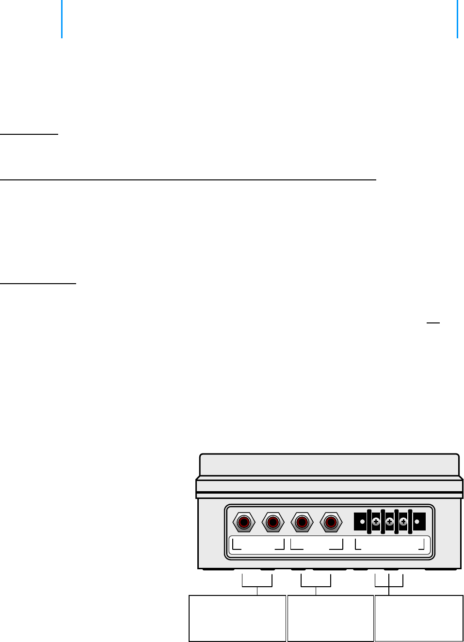
1 Getting Started
The LPA-Series receiver is designed for interface to existing wired Public Address
systems to allow PA announcements using VHF or UHF business band, FRS, or
MURS radios.
Major Benefit: The LPA receiver allows all the wired speakers in a PA/Intercom system immediately accessible via a
2-way radio/base station/ etc. The LPA receiver can be connected to an existing wired system. An
LM and LPA receiver system can be used side-by-side on the same frequency.
What is The Difference b/w The LM-V150/U450 Receiver and The LPA-V150/U450 Receiver?
• The LM Receiver (#LM-V150/U450) has a built-in audio amplifier. The built-in audio amplifier allows the LM receiver
by itself to drive up to 2 Ritron PA horn speakers. The LM receiver and included PA Horn speaker is what we call a
stand-alone wireless PA system.
• LPA Receiver (#LPA-V150/U450) does not have a built-in PA amplifier. The LPA receiver is designed to be
connected to an existing PA/intercom system with its own PA amplifier and wired speakers.
• The LPA receiver does not include a back-up battery since it is merely a component of a larger system usually
powered by AC and its own battery back-up system.
Features/Benefits:
• Available in VHF (150-162 MHz) and UHF (450-470MHz) frequency bands. Provides compatibility with business
band 2-way radios, License-FREE VHF business band radios (MURS), Family Radio Service and GMRS radios.
• Provides interconnection to the Public Address amplifier through a high impedance, unbalanced AUX input OR a
600Ω, balanced MIC input. Allows personnel to remain mobile while providing access via 2-way radio access to
existing PA speakers located throughout the facility.
• If the AUX input of the PA/Intercom amplifier is already used (ie: stereo tuner for background music) the LPA-
Series is installed in-between the audio source (stereo tuner) and the PA/Intercom amplifier. When the LPA-Series
receives a message the audio source is interrupted and the received message is sent to the PA/Intercom amplifier
instead.
• “Record and Play” allows use of radios in close proximity to PA speakers without feedback. The LPA-Series
records/buffers received messages up to 30 seconds in length, then plays them over the PA immediately after
releasing the PTT button on the radio.
• Easy “Plug and Play” installation.
• Programmable volume control adjusts
audio output level 5-99%. Allows custom
adjustment for most applications.
AUX OUT connects to
the high impedance,
unbalanced AUX input
of the PA amplifier.
If used, a CD player,
tuner or tape player
connects to AUX IN
600Ω BALANCED
connects to the
600Ω balanced input
of the PA amplifier.
L R
AUX IN HOT GND COLD
600Ω BALANCED
L R
AUX OUT
• Selective signaling includes QC, DQC,
Selcall, 2-Tone to provide an added layer
of access control to the PA system.
• Pre-announce tone (similar to existing PA
systems) with programmable on/off and
volume level.
• NOAA Weather Alert (VHF only).
• Field or PC programmable to frequencies
within the respective band (i.e. 150-165
MHz, 450-470 MHz).
• The LPA-Series is for interface only to an
existing PA system, it cannot drive a
loudspeaker by itself.
• The LPA-Series is for indoor use ONLY.
Section 1 Getting Started 1
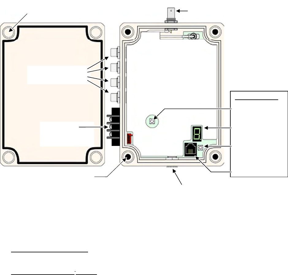
1.1 LPA-Series receiver assembly
The LPA-Series receiver is on any time power is applied. The receiver case must be opened to install the
Mounting Bracket or to program the LPA-Series receiver.
Section 1 Getting Started 2
1. Loosen the (4) captive screws in the front corners of the case. These screws are captive to the housing; to
prevent damaging them, DO NOT remove the screws from the housing.
2. Separate the case front from the case back.
3. Install the Mounting Brackets by inserting the 4 sealed screws included in the Mounting Bracket kit into the
4 pre-drilled holes shown above. Secure the Mounting Brackets to the case using the lockwashers and nuts
included in the Mounting Bracket kit.
4. Program the LPA-Series receiver per the instructions in the Programming section of this manual, leaving the
RPS-1A power supply connected to the radio. Press the Enter button twice before re-assembling the case to
be sure the LPA-Series receiver is reset and ready for operation.
5. Carefully position the case front onto the case back. Secure the case halves by tightening the 4 captive
screws in the front corners of the case.
PROGRAMMING
Enter Button
Program Display
Program Button
RJ-11 Program
Cable Connector
DC Power Connecto
r
for RPS
-
1A
RCA Phono Jacks
For AUX IN and OUT
BNC Antenna Connector
for AFB
-
1545
Pre-drilled holes for
Mounting Bracket (4 corners)
Captive Plastic Case
Screws
(
4 corners
)
Barrier Strip
For 600Ω
Balanced Output

1.2 Paging the LPA-Series receiver
The LPA-Series receiver can be paged with 2-way radios programmed for Quiet Call (CTCSS), Digital Quiet Call
(DCS), 2-Tone Paging, or Selcall paging formats. Each format offers a unique method of paging the LPA receiver.
Refer to the Programming section of this manual for specific instructions on programming your LPA receiver to one
of these selective signaling formats.
Section 1 Getting Started 3
Ritron strongly recommends operation of the LPA-Series receiver with one
of the following selective signaling formats enabled.
Paging the LPA-Series receiver with Quiet Call (CTCSS) only:
• To page the LPA receiver a user simply presses the 2-way radio’s PTT and speaks while on the LPA
channel.
• Your 2-way radio must be programmed for a channel dedicated to LPA receiver operation. Only those
radios programmed with the LPA channel will be able to access the loudspeaker.
• The 2-way radio’s LPA channel and the LPA receiver must be programmed for the same QC code. All
Ritron radios offer 50 different field-programmable QC codes from which to choose.
Paging the LPA-Series receiver with Digital Quiet Call (DCS) only:
• To page the LPA receiver a user simply presses the 2-way radio’s PTT and speaks while on the LPA
channel.
• Your 2-way radio must be programmed for a channel dedicated to LPA receiver operation. Only those
radios programmed with the LPA channel will be able to access the loudspeaker.
• The 2-way radio’s LPA channel and the LPA receiver must be programmed for the same DQC code.
All Ritron radios offer 104 different field-programmable DQC codes from which to choose.
Paging the LPA-Series receiver with 2-Tone Paging:
• To page the LPA receiver the 2-way radio must first send the correct 2-Tone Paging code. Once
access to the LPA receiver is accomplished, the user simply presses the 2-way radio’s PTT and speaks
while on the LPA channel. After a period of inactivity the LPA receiver is automatically reset, and will
then require the correct 2-Tone Paging code to re-gain access.
• Only 2-way radios programmed to send the correct 2-Tone code on the LPA channel can access the
LPA receiver. However, once access is gained, any 2-way radio that operates on the LPA channel can
access the LPA receiver up until the time that the LPA receiver has automatically reset.
• Can be used in conjunction with QC or DQC for added security. The 2-way radio and the LPA receiver
must be programmed for the same QC or DQC code.
Paging the LPA-Series receiver with Selcall:
• To page the LPA receiver the 2-way radio must be programmed to send the correct Selcall code every
time the PTT is pressed. The user simply presses the 2-way radio’s PTT and speaks while on the LPA
channel.
• Only 2-way radios programmed to send the correct Selcall code on the LPA channel can access the
LPA receiver.
• Can be used in conjunction with QC or DQC for added security. The 2-way radio and the LPA receiver
must be programmed for the same QC or DQC code.

Ritron recommends the use of a dedicated channel frequency for LPA
operation.
When operating on unique frequencies dedicated to LPA operation:
• Your 2-way radios must be programmed for a channel dedicated to LPA operation.
• LPA-Series receiver operation is limited to radios programmed with the dedicated LPA channel.
• The use of 2-tone or Selcall paging to address the LPA receiver is not required, but can still be used if
additional access security is desired.
• Without 2-tone or Selcall paging the LPA receiver can be addressed by simply selecting the LPA
channel on your 2-way radio and pressing the PTT button to talk.
• You may need to license additional frequencies (not necessary with LPA-V150 programmed for MURS
frequencies, see Table 1 in the Programming section).
When operating on your normal 2-way communication frequencies:
• Messages received by the LPA-Series receiver and broadcast on the wired PA system are also heard
on your 2-way radios.
• LPA operation is not possible when the channel is being used for 2-way communications.
• The use of 2-tone or Selcall paging is required to address the LPA receiver, otherwise all 2-way
communication is heard on the wired PA system.
• Any user on your 2-way channel can broadcast over the wired PA system once the LPA receiver is
activated, even if their 2-way radio is not programmed with the correct 2-tone paging code.
• There is no need to license additional frequencies.
Section 1 Getting Started 4
1.3 Compatibility with other RITRON model radios
The LPA-Series receiver is available in both VHF (LPA-V150, 150-165 MHz) and UHF (LPA-U450, 450-470 MHz)
business band frequencies. LPA receivers can be accessed with radios programmed for Quiet Call (CTCSS),
Digital Quiet Call (DCS), 2-Tone Paging, or Selcall paging formats. The following chart can be used to determine
compatibility with existing Ritron radios.
VHF models compatible with LPA-V150 UHF models compatible with LPA-U450
2- 2-
Model Type QC DQC Tone Selcall Model Type QC DQC Tone Selcall
JMX-141D Portable √ JMX-441D Portable
√
JMX-144D Portable √ √ √ JMX-444D Portable
√ √ √
JMX-146D Portable √ JMX-446D Portable
√ √ √
JBS-146D Base √ √ √ JBS-446D Base √ √ √
* J-V110 Portable √ √ √ * J-U410 Portable
√ √ √
RPM-160 Mobile √ √ √ √ RPM-460 Mobile √ √ √ √
RQX-151 Callbox √ √ RQX-451 Callbox
√ √
RQX-156 Callbox √ √ √ RQX-456 Callbox √ √ √
RQX-157 Callbox √ √ √ RQX-457 Callbox √ √ √
SLX-100 Portable
√ √ √ √ SLX-400 Portable √ √ √ √
* 2-Tone paging available with Rev 6 Firmware Only. See label inside radio battery compartment for
firmware revision.

2 Installation
Proper installation of the LPA-Series receiver is critical to the performance and
overall satisfaction with your system. With careful consideration and planning the
LPA-Series can receive a radio signal from up to a mile away and broadcast it over
your wired PA system. This section will help you plan an installation that is best
suited for your environment.
2.1 Radio coverage site survey
Ritron recommends that you do a “radio coverage site survey” before
permanently installing the LPA-Series receiver.
This will require 2 people and 2 charged portable radios.
Every building is different, and therefore, no “single” rule applies when it comes to where to install the LPA receiver
and antenna for optimal coverage. Ideally, you would like to install the LPA-Series receiver in close proximity to
the wired PA amplifier for easy installation. Begin your site survey by locating person #1 at the wired PA amplifier
to see if a simple installation is possible. If that is not possible, an alterative site must be found where:
1. AC power is available for the LPA receiver.
2. A shielded, twisted pair cable can be routed from the LPA receiver to the PA amplifier.
In general, the antenna of the LPA receiver is the “pivot” point for all communication. We’re trying to optimize the
location of the antenna in order to reduce the obstructions and distance the radio signal must travel in order to get
from any point in the desired coverage area to the antenna connected to the LPA receiver. By attempting to install
the ANTENNA for the LPA receiver “in the center” of the desired coverage area, we reduce the distance the radio
signal must travel by ½. If you’re attempting to cover a high rise building (e.g. 15 floors), go to a location half way
up (e.g. 7th floor), and in the center of the building.
Radio range can be extended with the use of an external
antenna.
The antenna can be installed at a higher elevation than is possible with the
attached antenna.
The Ritron RAM-1545 VHF/UHF magnet-mount antenna has a 25 ft.
cable to allow optimum antenna location.
Preparing for the radio coverage site survey:
1. Charge the radio batteries for at least 12 hours.
2. When charged, make sure both radios are set to the same channel.
Note: If you do not intend to route LPA communications through a repeater, the portable radios should be set to
a channel programmed for direct radio-to-radio communication, NOT through the repeater.
Section 2 Installation 5
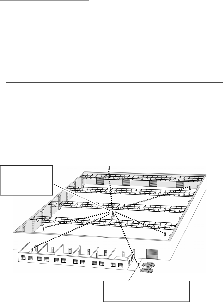
Conducting the radio coverage site survey:
1. Person #1 will take one portable radio and go to the location you would “most likely” install the antenna for the
LPA receiver (see FIG-2). This person will “simulate” the type of coverage you can expect, IF, the antenna for
the LPA receiver was installed in this location. If necessary, position this person on a ladder to more
accurately mimic the height you intend to mount the antenna.
BE ADVISED – you may have to try several heights and/or locations before settling on the best location.
2. While person #1 remains stationary, person #2 will take the second radio and “walk the site”. While “walking
the site” person #2 must attempt to maintain radio contact periodically with person #1. This survey process will
reveal whether or not radio coverage is acceptable IF you install the antenna at the person #1 location.
Generally speaking, coverage will be slightly better when the LPA receiver and antenna are permanently
installed.
3. If coverage is inadequate, Person #1 will need to relocate to a new location and repeat the process until range
and coverage are optimized.
Hints: Typically, the higher the antenna the better but, NOT always. Every site is different. Thick, reinforced
concrete, steel walls and vertical fire panels in ceilings can work to block the penetration of radio signals
creating dead spots. You may want to gradually lower the height of the antenna and/or its location and repeat
your site survey to see if coverage improves. It is best to change one variable at a time e.g. antenna height,
location and then repeat the process.
4. For sites where coverage is desired in multiple buildings, such as an office complex, an external mounted
antenna may be required. Before considering an external installation of the antenna, a site survey should be
attempted with person #1 positioned inside a centrally located building at the highest possible elevation (see
FIG-3). Person #2 will “walk the site”, communicating with person #1 from inside all buildings and at all
outside areas where radio coverage is desired.
Section 2 Installation 6
FIG-2: Conducting a radio site survey
Person #2 “walks the site”, stopping
frequently to communicate with person
#1 at the fixed, central location.
2
2
2
2
2
2
Person #1 remains at the
location you will install the
LPA receiver, possibly on
a ladder to simulate the
location of an external
mounted antenna.
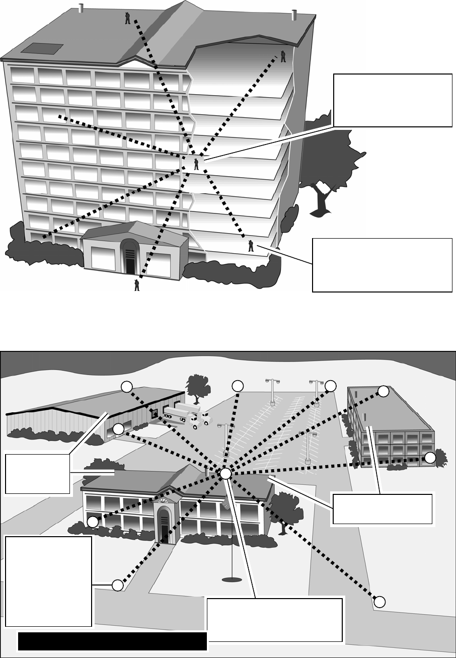
Section 2 Installation 7
Person #1 remains in a
fixed location, probably
located on a floor about
½ way up the building.
Person #2 “walks the site”,
stopping frequently on each
floor to communicate with
person #1 at the fixed location.
2
2
2
2
2
2
Alternative
locations for
person #1
Alternative locations
for person #1
Person #1 remains in a fixed
location on the top floor of a
centrally located building.
FIG-3: Multiple building site survey
2
2
2 2
2
2
2
2
1
Person #2 “walks
the site”, talking
to person #1
from within each
building and from
the perimeter of
the outside
covera
g
e area.
2
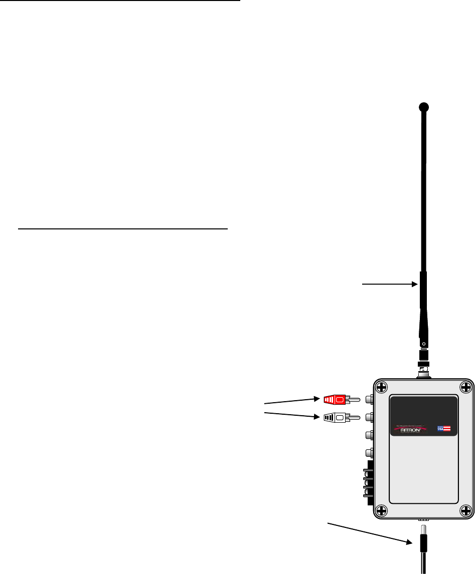
Installing a Magnetic Mount Antenna for the LPA-Series Receiver
A magnetic mount antenna should be installed in a location, which is at, or as close as possible to the best location as
determined by the site survey. The antenna’s magnetic base must be attached to a piece of metal (i.e. steel or iron).
The antenna comes with 12 feet of attached co-axial cable* so you can remotely locate the antenna up to 12 feet away
from the LPA-Series receiver. The antenna cable MUST run directly away from the LPA receiver.
* Do NOT attempt to cut, shorten or splice this cable in any way.
For best performance the magnetic mount antenna must be:
• Mounted on a metal surface e.g. steel or iron. This metal mounting surface MUST be at least 2 feet square with
the antenna positioned in the center. The antenna’s internal magnet will secure it to the surface. Do NOT place
adhesives between the bottom of the antenna mounting surface and the metal mounting surface itself.
• Orient the antenna so that the element itself is vertical. The antenna can be mounted upside down with no affect
on performance. Just make sure the antenna element is vertical.
• Mounted away from other metal objects, walls, and structures. Avoid surrounding the antenna or “shielding” it by
locating it too closely to metal walls, inside an elevator shaft, in recessed girders, firewalls or ceilings.
Section 2 Installation 8
2.2 LPA-Series radio receiver installation
Installation of the LPA receiver is critical to the effective radio coverage of the radio PA
system. Without proper installation the maximum possible distance between the calling
radio and the LPA receiver will be significantly reduced.
Guidelines for installing the LPA-Series receiver:
• The radio receiver box must be located inside, out of the elements.
• For best radio coverage the LPA receiver should be installed in a central
location and as high up as possible.
• For maximum radio coverage the antenna should be in a vertical orientation
and should not be touching or surrounded by large metal objects. The receiver
box can be mounted horizontally as long as the antenna is in a vertical
position.
• Do not install the LPA receiver in a high traffic location with the possibility that
the receiver box would be struck, become unplugged, or disconnected from the
PA amplifier.
L
o
u
d
M
o
u
t
h
L
o
u
d
M
o
u
t
h
• If connection to the PA amplifier is via it’s AUX IN, the
LPA receiver must be within 6 ft. of the PA amplifier.
• Do not wind, loop or otherwise allow the power cord from the RPS-1A
power cube to contact the antenna. The power cord should be routed
away from the antenna.
• Be sure there is a convenient source of 110VAC power for the RPS-
1A power cube.
RPS-1A
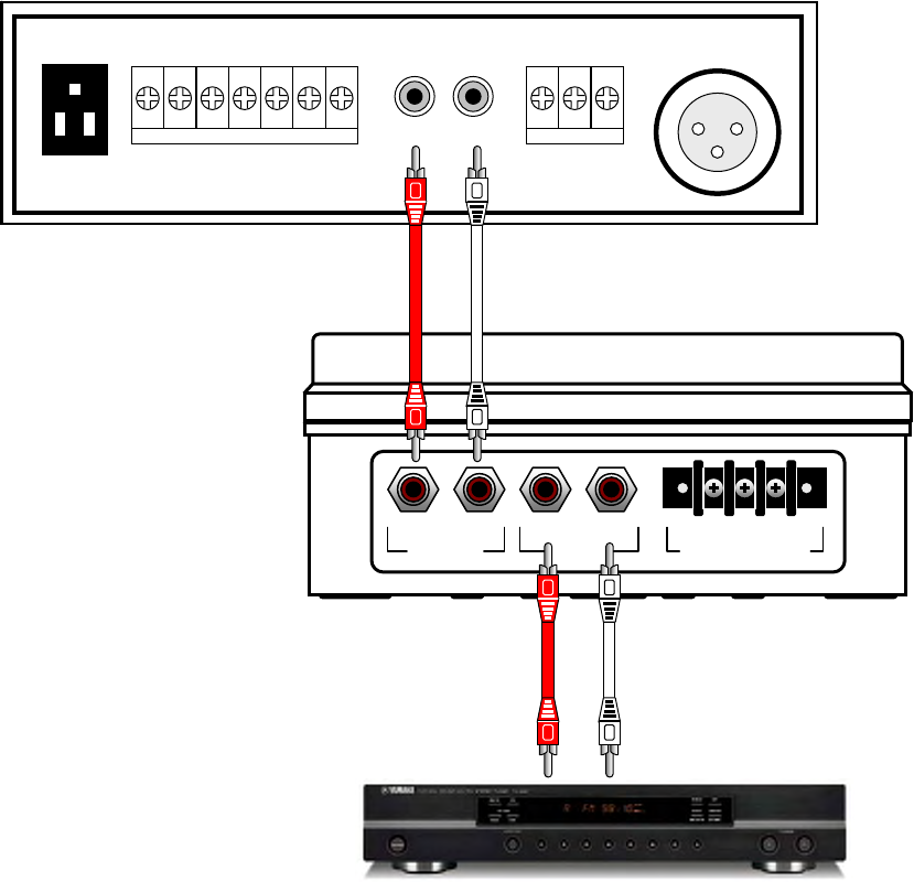
2.3 LPA-Series AUX IN installation
The LPA-Series receiver can connect to the AUX INPUT of a public address
amplifier if the LPA receiver is installed in close proximity to the PA amplifier.
• The RCA phono cables required for interconnection should be no longer than 6 feet. Installations requiring
LPA receiver location greater than 6 feet from the PA amplifier must use the 600Ω balanced output.
• If the AUX INPUT of the PA amplifier is already used, the LPA receiver is connected between the AUX audio
source (stereo tuner, cd player, tape player, etc.) and the PA amplifier as shown.
• Audio from the AUX audio source will be routed to the PA amplifier as normal when the LPA receiver is not
in use. When an LPA radio message is received, the LPA receiver will disconnect the AUX audio source
and replace it with the radio transmission. Once the radio message is complete the AUX audio source is re-
connected to the PA amplifier.
• When using the PA amplifier AUX INPUT it is important to remember that received messages from the LPA
receiver will be treated exactly the same way any other audio device connected to the AUX INPUT. On
many PA amplifiers the AUX INPUT audio is automatically muted whenever audio is present on the MIC
INPUT. Check the owner’s manual for the PA amplifier to determine AUX INPUT operation and the effect it
will have on LPA operation.
600
Section 2 Installation 9
RCA PHONO CABLES
6 FT. MAXIMUM
RCA PHONO CABLES
STEREO TUNER
PUBLIC ADDRESS AMPLIFIER
(REAR PANEL)
Ω
MIC-1
GND COM HOT
600
Ω
MIC-2
SPEAKER A
U
X INP
U
COM 4Ω 8Ω 16Ω COM 25V 70V
T
L R
UNSWITCHED
L R
AUX IN HOT GND COLD
600Ω BALANCED
L R
AUX OUT
LPA-SERIES RECIEVER
(SIDE PANEL)
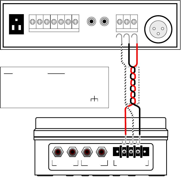
2.4 LPA-Series 600Ω BALANCED installation
The LPA-Series receiver can be connected to the 600Ω balanced MIC INPUT of
a public address amplifier when the LPA receiver is not located close to the PA
amplifier.
• When an LPA radio message is received, the LPA receiver will send the audio to the 600 Ω microphone input
of the PA amplifier.
• A typical balanced cable contains two identical wires, which are twisted together and then wrapped with a third
conductor (foil or braid) that acts as a shield. The wires are twisted together, to reduce interference from
electromagnetic induction. Twisting makes the loop area between the conductors as small as possible, and
ensures that a magnetic field that passes equally through adjacent loops will induce equal but opposite
currents, which cancel out. The separate shield of a balanced audio connection also yields a noise rejection
advantage over an unbalanced two-conductor arrangement (such as AUX IN) where the shield must also act
as the signal return wire. Any noise currents induced into a balanced audio shield will not therefore be directly
modulated onto the signal, whereas in a two-conductor system they will be. This also prevents ground loop
problems, by separating the shield/chassis from signal ground.
NOTE: To minimize noise it is often necessary to connect the ground shield at only one end of the cable.
Section 2 Installation 10
LP
A
PA Amp
HOT connects to HOT or “+” or POS
COLD connects to COLD or “-“ or NEG or COM
GND connects to GND or CHASSIS or
600
Ω
MIC-1
PUBLIC ADDRESS AMPLIFIER
GND COM HOT
600 Ω
MIC-2
SPEAKER A
U
X INP
U
COM 4Ω 8Ω 16Ω COM 25V 70V
T
L R
UNSWITCHED
SHIELDED,
TWISTED PAIR
L R
AUX IN HOT GND COLD
600Ω BALANCED
L R
AUX OUT
LPA-SERIES RECEIVER
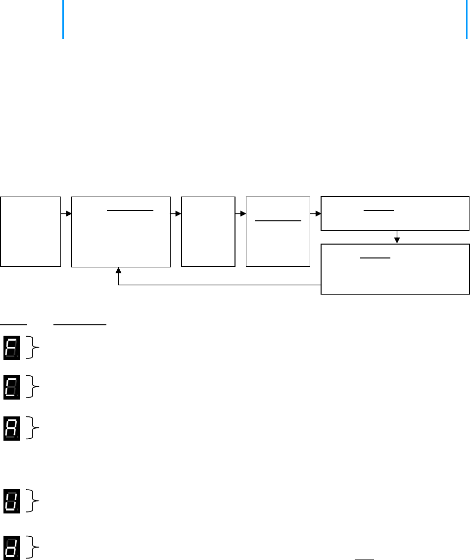
3 Programming
For most installations the LPA-Series receiver can be programmed in the field
without the need for Ritron PC Programmer 12.0.1. Field programming is
accomplished in 3 easy steps. First, the radio frequency and tone codes are
entered. Second, the selective signaling code is entered (if used). Third, the LPA-
Series options and volume setting are entered.
3.1 LPA-Series Field Programming Overview
Press ENTER
Section 3 Programming 11
Program
odes
C Table Codes
Enter a 2-digit Frequency code from Table 1 and a 2-digit QC code from Table 2 or
nter a 2-digit Frequency code from Table 1 and a 3-digit DQC code from Table 3.
E
or
Enter a 2-digit, 2-Tone Paging code from Table 4
Enter any 3 – digit Selcall Paging Code. 7-
E r nte a 2-digit Feature code from Table 5 to:
• Enable or disable a Pre-Announce Tone.
• Enable or disable Record and Play operation.
• Enable or disable Weather Alert feature (VHF models only)
• Reset LPA-Series receiver to Factory default programming.
Enter the desired Speaker Volume Level as a 2 –digit number from 05 – 99.
Enter the 1-digit NOAA Weather Frequency code from Table 6 (VHF models only)
This only programs the NOAA weather frequency, the Weather Alert feature must be enabled using
the Special Features code in Table 5.
Place the
LPA-Series
receiver
into
Program
mode.
Use PROGRAM
button to scroll to
one of the following
Program Code
characters:
[F], [C], [A], [U], [d]
Pause, a
hyphen
will
appear
on the
display.
Using the
PROGRAM button to save
programming entry.
button,
enter the
desired
Table Code. Press ENTER button a second
time to Exit programming.
or
Proceed with next program entry.
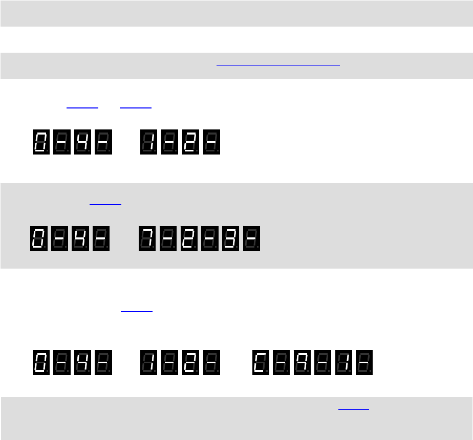
3.2 Readout Current Frequency, Tone and Selective Signaling Codes
1. Loosen the (4) captive screws in the front corners of the case. These screws are captive to the housing; to
prevent damaging them, DO NOT remove the screws from the housing.
. Separate the case front from the case back, leaving the RPS-1A power supply connected to the radio.
2
3. Press and release the PROGRAM button (See LPA-Series receiver assembly on page 2 for location). The
radio will immediately begin to display a series of digits; with each digit separated by a hyphen.
4. Write down the all the digits. The first two digits indicate the frequency code and the next two digits the tone
code; see Table 1 and Table 2 on page 16. In this example an LPA-U450 is programmed to operate on the
“Brown Dot” frequency of 464.500 MHz (Frequency code “04”) with 100.0 Hz tone (Tone code “12”).
FREQUENCY CODE TONE CODE
5. If a 5th digit is displayed, the LPA receiver has been programmed for DQC and the last three digits indicate the
DQC code; see Table 3 on page 16. In this example an LPA-U450 was programmed to operate on the
“Brown Dot” frequency of 464.500 MHz (Frequency code “04”) with a DQC code of “723”.
FREQUENCY CODE DQC CODE
6. If more than 5 digits are displayed, the radio has been programmed for Selective Signaling Decode. The
frequency and tone codes will be displayed, followed by a “C”, then the radio will display either the 2-digit, 2-
Tone paging code (see Table 4 on 16) or the 3-7 digit Selcall code. In this example an LPA-U450 was
programmed to operate on the “Brown Dot” frequency of 464.500 MHz (Frequency code “04”) with 100.0 Hz
tone (Tone code “12”) and 2-tone paging decode frequencies of 330.5 Hz and 569.1 Hz (2-Tone code “91”)
7. If the LPA-Series receiver is PC programmed with any frequency not listed in Table 1 on page 16, the radio
will display a code "99" for the frequency code. The PC programmer will be required to readout the radios
equency programming. fr
FREQUENCY CODE TONE CODE PAGING CODE
8. Normal radio operation resumes after the programming information has been displayed.
Section 3 Programming 12
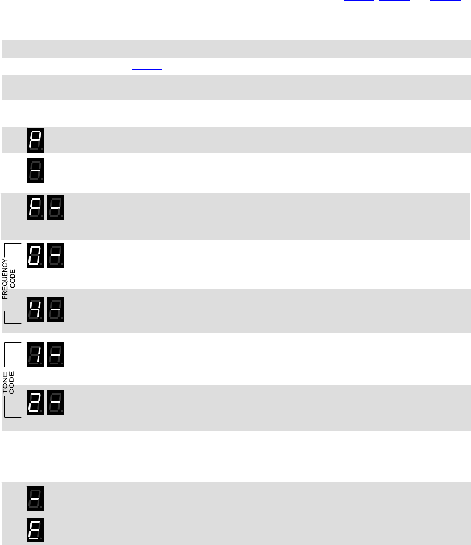
3.3 Program Frequency & Tone Codes
To match other radios, the owner can select Frequency, Tone and DQC Codes from Table 1, Table 2 and Table 3.
In our example, we will program an LPA-U450 to operate on the "Brown Dot" frequency of 464.500 MHz with 100.0
Hz tone.
04
12
1. Refer to Table 1 to determine the two-digit frequency code and write it down.
2. Refer to Table 2 to determine the two-digit tone code for 100.0 Hz and write it down.
3. Loosen the (4) captive screws in the front corners of the case. These screws are captive to
the housing; to prevent damaging them, DO NOT remove the screws from the housing.
4. Separate the case front from the case back, leaving the RPS-1A power supply connected
to the radio.
5. Press and HOLD the PROGRAM button. A "P" will appear on the program display as you
enter program mode and the radio will beep rapidly.
6. Release the PROGRAM button after the beeping has stopped. The radio will emit a triple
beep indicating that the radio is in program mode and a hyphen will appear on the program
display.
7. Scroll to the character “F” by clicking the PROGRAM button until the program display
shows the correct character. Pause—the radio will sound a low tone and show a hyphen
across the center of the display to indicate that it is ready to accept the first digit of the
frequency code.
8. Enter the 1st digit of the frequency code by clicking the PROGRAM button until the
program display shows the desired number. Pause—the radio will sound a low tone and
show a hyphen across the center of the display to indicate that it is ready to accept the
next digit.
9. Enter the 2nd digit of the frequency code by clicking the PROGRAM button until the
program display shows the desired number. Pause—the radio sounds a low tone and will
show a hyphen across the center of the display to indicate that it is ready to accept the
next digit.
10. Enter the 1st digit of the tone code (or 1st digit of the DQC code) by clicking the PROGRAM
button until the program display shows the desired number. Pause—the radio sounds a
low tone and will show a hyphen across the center of the display to indicate that it is ready
to accept the next digit.
11. Enter the 2nd digit of the tone code (or 2nd digit of the DQC code) by clicking the
PROGRAM button until the program display shows the desired number. Pause—the radio
sounds a low tone and will show a hyphen across the center of the display to indicate that
it is ready to accept the next digit.
12. FOR DQC CODES ONLY – Enter the 3rd digit of the DQC code by clicking the PROGRAM
button until the program display shows the desired number. Pause—the radio sounds a
low tone and will show a hyphen across the center of the display to indicate that it is ready
to accept the next digit.
13. Press and release the ENTER button to save your programming. A triple beep will sound to
indicate that programming was successful and a hyphen will appear on the program
display. The radio is now ready for another program entry.
NOTE: An error tone will sound if you attempt to save an incorrect code, an "E" will appear
on the display. Check the digits you are attempting to enter, then re-enter.
14. Once you have made your final program entry, press the ENTER button a final time to exit
programming mode. The Program display will be blank and the radio will be ready for use.
The LPA-Series receiver will exit program mode automatically after 30 seconds if no
program entries are attempted.
Section 3 Programming 13

Section 3 Programming 14
Table 2: Interference Eliminator Programmable QC Tone Codes
Table 3: Digital Interference Eliminator Programmable DQC Tone Codes
Table 1: Programmable Frequency Codes
VHF Business Band
Code Frequency Color Dot BW
03 151.625 Red Dot 25
04 151.955 Purple Dot 25
05 151.925 25
06 154.540 25
07 154.515 25
08 154.655 25
10 151.715 25
09 151.685 25
11 151.775 25
12 151.805 25
13 151.835 25
14 151.895 25
15 154.490 25
16 151.655 25
17 151.745 25
18 151.865 25
24 151.700 12.5
25 151.760 12.5
26 152.700 25
99 Custom programmed ---
VHF MURS**
01 154.600 Green Dot 25
02 154.570 Blue Dot 25
19 151.820 MURS 12.5
20 151.880 MURS 12.5
21 151.940 MURS 12.5
22 154.600 MURS 12.5
23 154.570 MURS 12.5
UHF Business Band
Code Frequency Color Dot BW
01 467.7625 J 25
02 467.8125 K 25
03 464.5500 Yellow Dot 25
04 464.5000 Brown Dot 25
05 467.8500 Silver Star 25
06 467.8750 Gold Star 25
07 467.9000 Red Star 25
08 467.9250 Blue Star 25
09 469.2625 25
10 462.5750 White Dot 25
11 462.6250 Black Dot 25
12 462.6750 Orange Dot 25
13 464.3250 25
14 464.8250 25
15 469.5000 25
16 469.5500 25
17 463.2625 25
18 464.9125 25
19 464.6000 25
20 464.7000 25
21 462.7250 25
22 464.5000 12.5
23 464.5500 12.5
24 467.7625 12.5
25 467.8125 12.5
26 467.8500 12.5
27 467.8750 12.5
28 467.9000 12.5
29 467.9250 12.5
30 461.0375 12.5
31 461.0625 12.5
UHF Business Band
Code Frequency Color Dot BW
32 461.0875 12.5
33 461.1125 12.5
34 461.1375 12.5
35 461.1625 12.5
36 461.1875 12.5
37 461.2125 12.5
38 461.2375 12.5
39 461.2625 12.5
40 461.2875 12.5
41 461.3125 12.5
42 461.3375 12.5
43 461.3625 12.5
44 462.7625 12.5
45 462.7875 12.5
46 462.8125 12.5
47 462.8375 12.5
48 462.8625 12.5
49 462.8875 12.5
50 462.9125 12.5
51 464.4875 12.5
52 464.5125 12.5
53 464.5375 12.5
54 464.5625 12.5
55 466.0375 12.5
56 466.0625 12.5
57 466.0875 12.5
58 466.1125 12.5
59 466.1375 12.5
60 466.1625 12.5
61 466.1875 12.5
62 466.2125 12.5
UHF Business Band
Code Frequency Color Dot BW
63 466.2375 12.5
64 466.2625 12.5
65 466.2875 12.5
66 466.3125 12.5
67 466.3375 12.5
68 466.3625 12.5
69 467.7875 12.5
70 467.8375 12.5
71 467.8625 12.5
72 467.8875 12.5
73 467.9125 12.5
74 469.4875 12.5
75 469.5125 12.5
76 469.5375 12.5
77 469.5625 12.5
99 Custom programmed ----
Canadian Models
UHF Canada
01 458.6625 25
02 469.2625 25
VHF Canada
01 151.055 25
02 151.115 25
British Columbia
01 154.100 25
02 158.940 25
Notes: ** MURS frequencies do not require an FCC license. All other frequencies require an FCC license.
• BW is the bandwidth in kHz. 12.5 kHz = narrow band channel, 25 kHz = wide band channel.
Code Frequency
01 67.0
02 71.9
03 74.4
04 77.0
05 79.7
06 82.5
07 85.4
08 88.5
09 91.5
Code Frequency
10 94.8
11 97.4
12 100.0
13 103.5
14 107.2
15 110.9
16 114.8
17 118.8
18 123.0
Code Frequency
19 127.3
20 131.8
21 136.5
22 141.3
23 146.2
24 151.4
25 156.7
26 162.2
27 167.9
Code Frequency
28 173.8
29 179.9
30 186.2
31 192.8
32 203.5
33 210.7
34 218.1
35 225.7
36 233.6
Code Frequency
37 241.8
38 250.3
39 69.4
40 159.8
41 165.5
42 171.3
43 177.3
44 No Tone
45 183.5
Code Frequency
46 189.9
47 196.6
48 199.5
49 206.5
50 229.1
51 254.1
00 No Tone
Code
023
025
026
031
032
036
043
047
051
053
054
Code
065
071
072
073
074
114
115
116
122
125
131
Code
132
134
143
145
152
155
156
162
165
172
174
Code
205
212
223
225
226
243
244
245
246
251
252
Code
255
261
263
265
266
271
274
306
311
315
325
Code
331
332
343
346
351
356
364
365
371
411
412
Code
413
423
431
432
445
446
452
454
455
462
464
Code
465
466
503
506
516
523
532
546
565
606
662
Code
612
624
627
631
632
645
654
664
703
712
723
Code
731
732
734
743
754
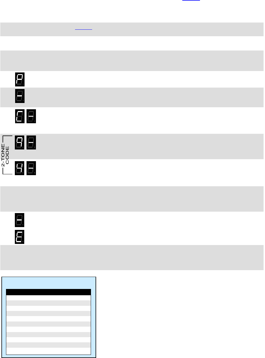
3.4 Program Paging Codes
For paging, it is desirable to program the LPA-Series receiver for 2-Tone or Selcall operation. The user is able to
field program the radio for one of the 9 pre-determined 2-tone pairs specified in Table 4, or for a 3-7 digit Selcall
code. 2-Tone codes correspond to field programmable 2-Tone encode (transmit) codes available in other RITRON
portable and base radios. In our example we will program an LM-U450 to operate with 2-Tone Paging Code 94
frequencies of 389.0 and 669.9 Hz.
94 1. Refer to Table 4 to determine the two-digit code for 2-tone decode on 389.0 and 669.9 Hz
and write it down.
2. Loosen the (4) captive screws in the front corners of the case. These screws are captive to
the housing; to prevent damaging them, DO NOT remove the screws from the housing.
3. Separate the case front from the case back, leaving the RPS-1A power supply connected
to the radio.
4. Press and HOLD the PROGRAM button. A "P" will appear on the program display as you
enter program mode and the radio will beep rapidly.
5. Release the PROGRAM button after the beeping has stopped. The radio will emit a triple
beep indicating that the radio is in program mode and a hyphen will appear on the program
display.
6. Scroll to the character “C” by clicking the PROGRAM button until the program display
shows the correct character. Pause—the radio will sound a low tone and show a hyphen
across the center of the display to indicate that it is ready to accept the first digit of the 2-
Tone or Selcall code.
7. Enter the 1st digit of the 2-Tone or Selcall code by clicking the PROGRAM button until the
program display shows the desired number. Pause—the radio will sound a low tone and
show a hyphen across the center of the display to indicate that it is ready to accept the
next digit.
8. Enter the 2nd digit of the 2-Tone or Selcall code by clicking the PROGRAM button until the
program display shows the desired number. Pause—the radio sounds a low tone and
show a hyphen across the center of the display to indicate that it is ready to accept the
next digit.
9. FOR SELCALL CODES ONLY – Enter the 3rd, 4th, 5th, 6th, and 7th digits of the Selcall code
by clicking the PROGRAM button until the program display shows the desired number.
Pause—the radio sounds a low tone and will show a hyphen across the center of the
display to indicate that it is ready to accept the next digit.
10. Press and release the ENTER button to save your programming. A triple beep will sound to
indicate that programming was successful and a hyphen will appear on the program
display. The radio is now ready for another program entry.
NOTE: An error tone will sound if you attempt to save an incorrect code, an "E" will appear
on the display. Check the digits you are attempting to enter, then re-enter.
11. Once you have made your final program entry, press the ENTER button a final time to exit
programming mode. The Program display will be blank and the radio will be ready for use.
The LPA-Series receiver will exit program mode automatically after 30 seconds if no
program entries are attempted.
Section 3 Programming 15
Table 4: 2-Tone Paging Codes
Code Tone 1 Tone 2
90 * *
91 330.5 569.1
92 349.0 600.9
93 368.5 634.5
94 389.0 669.9
95 410.8 707.3
96 433.7 746.8
97 457.9 788.5
98 483.5 832.5
99 330.5 600.9
00 No Selective Signaling
IMPORTANT NOTE:
* If the LPA-Series receiver displays 2-Tone Paging Code “90”
on readout, it has been PC programmed for custom 2-Tone
frequencies. Entering code “90” will cause the LPA-Series
receiver to operate on the PC programmed custom 2-Tone
frequencies.
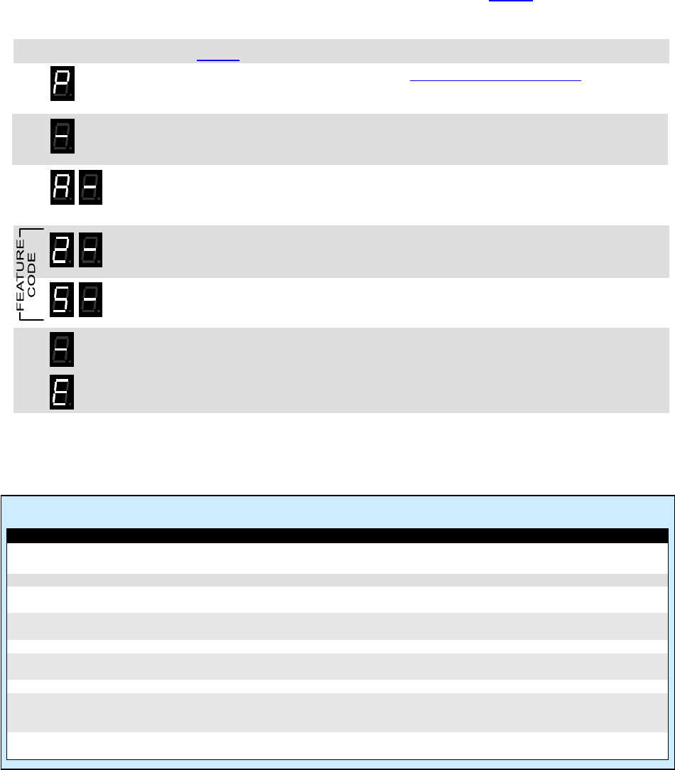
3.5 Program LPA-Series Features
The LPA-Series receiver can be field programmed for a variety of features. Refer to Table 5 for the two digit codes
available for field programming. In our example we will program an LPA-U450 for Record and Play operation. The
LPA-Series receiver is set from the factory with these √ options enabled.
13 1. Refer to Table 5 to determine the two-digit feature code and write it down.
2. Press and HOLD the PROGRAM button (See LPA-Series receiver assembly on page 2 for
location). A "P" will appear on the program display as you enter program mode and the
radio will beep rapidly.
3. Release the PROGRAM button after the beeping has stopped. The radio will emit a triple
beep indicating that the radio is in program mode and a hyphen will appear on the program
display.
4. Scroll to the character “A” by clicking the PROGRAM button until the program display
shows the correct character. Pause—the radio will sound a low tone and show a hyphen
across the center of the display to indicate that it is ready to accept the first digit of the
Feature code.
5. Enter the 1st digit of the feature code by clicking the PROGRAM button until the program
display shows the desired number. Pause—the radio will sound a low tone and show a
hyphen across the center of the display to indicate that it is ready to accept the next digit.
6. Enter the 2nd digit of the feature code by clicking the PROGRAM button until the program
display shows the desired number. Pause—the radio sounds a low tone and will show a
hyphen across the center of the display to indicate that it is ready to accept the next digit.
7. Press and release the ENTER button to save your programming. A triple beep will sound to
indicate that programming was successful and a hyphen will appear on the program
display. The radio is now ready for another program entry.
NOTE: An error tone will sound if you attempt to save an incorrect code, an "E" will appear
on the display. Check the digits you are attempting to enter, then re-enter.
8. Once you have made your final program entry, press the ENTER button a final time to exit
programming mode. The Program display will be blank and the radio will be ready for use.
The LPA-Series receiver will exit program mode automatically after 30 seconds if no
program entries are attempted.
Table 5: Feature Codes
Code Feature Default Description
Special Features
21 Reset to Factory Defaults Resets Wireless Speaker to Factory default programming.
22 Display Radio Revision LPA receiver will display a sequence of 6 digits to identify operating code
revision. This is helpful when troubleshooting the radio.
23 Pre-Announce Tone – On √ Enable this feature to play a short tone over the PA system speakers
whenever the LPA receiver receives a signal.
24 Pre-Announce Tone – Off Disable Pre-Announce Tone
25 Record and Play – On When set received messages are recorded and played back over the PA
system speakers immediately after the received signal is removed.
26 Record and Play – Off √ Disable Record and Play feature
29 Weather Alert – On Enable this feature to receive local NOAA weather radio emergerncy
broadcasts from the National Weather Service and play them over the PA
system speaker. This feature is only available on the LPA-V150.
20 Weather Alert – Off √ Disable Weather Alert
Section 3 Programming 16
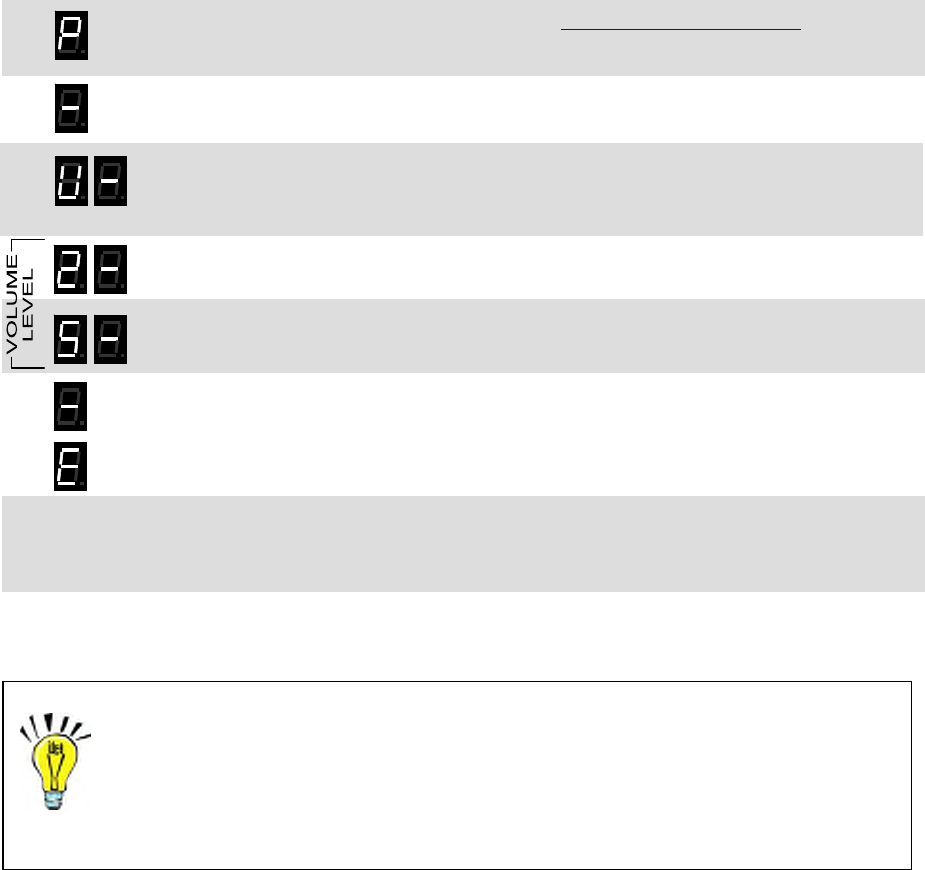
3.6 Program LPA-Series Volume
The LPA-Series receiver can be field programmed for any volume level between 05-99% by entering the volume
level as a 2-digit code. The LPA receiver is set from the factory with a 50% volume setting. If your PA amplifier
has independant volume control you should not have to adjust the LPA receiver volume. If there is no volume
control, or if the PA amplifier volume control is pre-set for background music, you can adjust the input level to the
PA amplifier by adjusting the LPA receiver volume. Field programming Volume Level sets both the voice and the
pre-announce tone volume levels. The PC programmer is required for independent programming of the voice and
the pre-announce tone volume.
In our example we will program an LPA-U450 for 25% Speaker Volume Level.
1. Press and HOLD the PROGRAM button (See LPA-Series receiver assembly on page 2 for
location). A "P" will appear on the program display as you enter program mode and the
radio will beep rapidly.
2. Release the PROGRAM button after the beeping has stopped. The radio will emit a triple
beep indicating that the radio is in program mode and a hyphen will appear on the program
display.
3. Scroll to the character “U” by clicking the PROGRAM button until the program display
shows the correct character. Pause—the radio will sound a low tone and show a hyphen
across the center of the display to indicate that it is ready to accept the first digit of the
volume setting.
4. Enter the 1st digit of the volume setting by clicking the PROGRAM button until the program
display shows the desired number. Pause—the radio will sound a low tone and show a
hyphen across the center of the display to indicate that it is ready to accept the next digit.
5. Enter the 2nd digit of the volume setting by clicking the PROGRAM button until the program
display shows the desired number. Pause—the radio sounds a low tone and will show a
hyphen across the center of the display to indicate that it is ready to accept the next digit.
6. Press and release the ENTER button to save your programming. A triple beep will sound to
indicate that programming was successful and a hyphen will appear on the program
display. The radio is now ready for another program entry.
NOTE: An error tone will sound if you attempt to save an incorrect code, an "E" will appear
on the display. Check the digits you are attempting to enter, then re-enter.
7. Once you have made your final program entry, press the ENTER button a final time to exit
programming mode. The Program display will be blank and the radio will be ready for use.
The LPA-Series receiver will exit program mode automatically after 30 seconds if no
program entries are attempted.
IMPORTANT NOTE: Volume settings below 10% are entered as a 2-digit code with a first digit “0”.
Checking the Current Volume Setting
To readout the current volume setting, follow the instructions above and enter a
volume setting code “00”. When you press the ENTER button the radio will
immediately begin to display the 2-digit volume setting; with each digit separated by
a hyphen.
Section 3 Programming 17
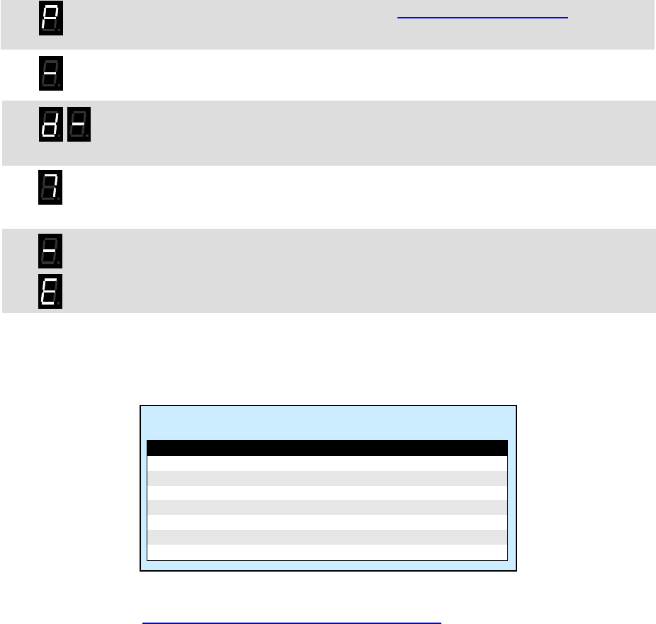
3.7 Program the NOAA Weather Frequency
The LPA-V150 can be programmed to play severe weather warnings originating from the National Weather service
that are broadcast on one of seven NOAA weather frequencies. The LPA-Series receiver is shipped from the
factory without a NOAA weather frequency selected. Before the Weather Alert feature can be used you must first
select the local NOAA frequency.
1. Press and HOLD the PROGRAM button (See LPA-Series receiver assembly on page 2 for
location). A "P" will appear on the program display as you enter program mode and the
radio will beep rapidly.
2. Release the PROGRAM button after the beeping has stopped. The radio will emit a triple
beep indicating that the radio is in program mode and a hyphen will appear on the program
display.
3. Scroll to the character “d” by clicking the PROGRAM button until the program display
shows the correct character. Pause—the radio will sound a low tone and show a hyphen
across the center of the display to indicate that it is ready to accept the NOAA Weather
Frequency code.
4. Enter the Weather Frequency code by clicking the PROGRAM button until the program
display shows the desired number. Pause—the radio sounds a low tone and will begin
playing the NOAA weather broadcast over the PA system speakers. Monitor the channel
for a few minutes to be sure it is the broadcast for your local area.
5. Press and release the ENTER button to save your programming. A triple beep will sound to
indicate that programming was successful and a hyphen will appear on the program
display. The radio is now ready for another program entry.
NOTE: An error tone will sound if you attempt to save an incorrect code, an "E" will appear
on the display. Check the digits you are attempting to enter, then re-enter.
6. Once you have made your final program entry, press the ENTER button a final time to exit
programming mode. The Program display will be blank and the radio will be ready for use.
The LPA-Series receiver will exit program mode automatically after 30 seconds if no
program entries are attempted.
Table 6: NOAA Weather Frequency Codes
Code Frequency
1 162.400 MHz
2 162.425 MHz
3 162.450 MHz
4 162.475 MHz
5 162.500 MHz
6 162.525 MHz
7 162.550 MHz
A complete list of NOAA weather frequencies available in your area can be found at
http://www.weather.gov/nwr/nwrbro.htm
Section 3 Programming 18

4 Operation
Once installed, operating the LPA-Series radio receiver requires no human contact.
Portable, base station or mobile 2-way radios can deliver voice messages directly
to a PA system with a simple press of the PTT button for either live or recorded
playback. This section describes the subtle differences in operation for various
LPA-Series options and installations.
4.1 Basic Operation
Basic operation is defined as a LPA-Series receiver programmed on a dedicated radio frequency with a QC or
DQC code. The receiver is also programmed for 50% volume and a pre-announce tone.
1. Move to an area that is away from any PA system speaker to prevent feedback.
y PA system speaker.
2. Be sure the microphone on the calling radio is pointed away from an
3. Set the portable, base station, or mobile radio to the LPA channel.
4. Monitor the channel before transmitting to be sure there are no other radio users on the LPA frequency.
5. Press and hold the PTT button and pause for about 1 second, allowing the pre-announce tone to be heard.
6. Speak into the radio microphone to broadcast your message over the PA system speakers. If other radios
essage.
are operating on the LPA channel they will also hear your m
7. Release the PTT button when your message is complete.
8. Return the portable, base station, or mobile radio to the normal operating channel.
Section 4 Operation 19
4.2 Selcall Paging
O 2 access the PA system.
y PA system speaker.
mitting to be sure there are no other radio users on the LPA frequency.
7. PA system speakers. If other radios
essage.
9. Return the portable, base station, or mobile radio to the normal operating channel.
th
To access the LPA-Series receiver the 2-way radio must be programmed to send the correct Selcall code every
time the PTT is pressed. The user simply presses the 2-way radio’s PTT and speaks while on the LPA channel.
nly -way radios programmed to send the correct Selcall code on the LPA channel can
1. Move to an area that is away from any PA system speaker to prevent feedback.
2. Be sure the microphone on the calling radio is pointed away from an
3. Set the portable, base station, or mobile radio to the LPA channel.
4. Monitor the channel before trans
5. Press and hold the PTT button.
6. Wait until the entire Selcall code has been sent, and then an additional 1 second for the pre-announce tone.
Speak into the radio microphone to broadcast your message over the
are operating on the LPA channel they will also hear your m
8. Release the PTT button when your message is complete.
Wi Selcall Paging operation:
Selcall paging can be used in conjunction with QC or DQC for added
• security. The 2-way radio and the
LPA receiver must be programmed for the same QC or DQC code.

Section 4 Operation 20
4.
2-way radio must first send the correct 2-Tone Paging code. Once access
to eaks while on the LPA
channel. After a peri orrect 2-
T P
e there are no other radio users on the LPA frequency.
nd, allowing the pre-announce tone to be heard.
ios
10. If the radio PTT is pressed again before the LPA receiver has reset, the message will be heard on the
-tone Paging code.
11.
th
3 2-Tone Paging
To access the LPA-Series receiver the
the PA system is accomplished, the user simply presses the 2-way radio’s PTT and sp
od of inactivity the LPA receiver will automatically reset, and will then require the c
one aging code to re-gain access.
1. Move to an area that is away from any PA system speaker to prevent feedback.
2. Be sure the microphone on the calling radio is pointed away from any PA system speaker.
3. Set the portable, base station, or mobile radio to the LPA channel.
4. Monitor the channel before transmitting to be sur
5. Send the correct 2-Tone Paging code. Refer to your 2-way radio’s user manual to determine how you send
2-tone paging codes.
6. Wait until the entire 2-tone code has been sent.
7. Press and hold the PTT button and pause for about 1 seco
8. Speak into the radio microphone to broadcast your message over the PA system speakers. If other rad
are operating on the LPA channel they will also hear your message.
9. Release the PTT button when your message is complete.
speaker without the need for a 2
Return the portable, base station, or mobile radio to the normal operating channel.
Wi 2-Tone Paging operation:
Once LPA receiver has decoded the correct 2-tone code any radio on the LPA channel can talk over
the speaker without the need for 2-tone paging.
•
g a signal before 2-tone is once again required
for access. Factory default Two-Tone Reset Time is 5 seconds.
• Can be used in conjunction with QC or DQC for added security. The 2-way radio and the LPA receiver
.
4.
W
th
m a when the PTT button is released on the 2-way radio.
S
1. ers on the LPA frequency.
e
n the LPA channel they will hear your message as you record it.
5. ard and the PA system speakers will begin playing your recorded
6. he he normal operating channel.
th
• After a 2-tone code has been successfully decoded, the programmable Two-Tone Reset Time sets the
length of time the LPA receiver can go without receivin
must be programmed for the same QC or DQC code
4 Record and Play (20 seconds of record time MAXIMUM)
hen 2-way radios are used in the same area as the PA system speakers, feedback may result that can render
e system unusable. For those applications the LPA-Series receiver can be programmed to record the incoming
ess ges and play them back over the PA system speakers
et the portable, base station, or mobile radio to the LPA channel.
Monitor the channel before transmitting to be sure there are no other radio us
2. Press and hold the PTT button on your 2-way radio.
3. Speak into the radio microphone to record your message into the LPA-Series receiver. If other radios ar
operating o
4. Release the PTT button when your message is complete.
The pre-announce tone will be he
message.
W n finished, return the portable, base station, or mobile radio to t
Wi Record and Play operation:
Recorded messages are lim
• ited to a maximum of 20 seconds.
• Any of the selective signaling options can be used in conjunction with Record and Play.
• The LPA receiver cannot record (buffer) an incoming message while in the process of playing a
er.
message on the speak

Section 4 Operation 21
4.
HF m lly play emergency weather warnings from the National Weather Service
th s 150 will listen for emergency
we h
5 Weather Alert
V odel LPA-V150 can automatica
at i broadcast on one of the seven NOAA weather frequencies. The LPA-V
at er broadcasts any time it is not being used. To use this feature the LPA-V150 must first be programmed for
ur local NOAA weather frequency.
yo
With Weather Alert operation:
The Weather Alert feature is only available on the LPA-V1
• 50 model.
• Your local NOAA weather frequency must be programmed into the LPA-V150 and the Weather Alert feature
must be ON per the instructions in the Programming section of this manual.
If a severe weather notification f• rom NOAA weather service occurs while the LPA-V150 is in use the
• LPA-
st the NOAA weather alert message non-stop until an end-of-message signal is received
or 2 minutes elapses. The LPA-150 cannot be used for regular paging operation as long as the weather
.ry Powered Operation
Fo
ex
batter
P
Ena henever the LPA receiver is battery powered to extend battery life. When enabled the LPA
inco e broadcast.
e, this may double the battery life.
ore speaker to allow the radio to
wake up.
Low Battery Alert Tone
Enable this feature whenever the LPA receiver is battery powered and a short tone will be heard at the end of
each broadcast to indicate that the batteries need replacement or recharging.
Weather Alert operation will not be activated.
When a severe weather notification from NOAA weather service activates Weather Alert operation, the
V150 will broadca
alert message is being played.
• The maximum Weather Alert Time is set at the factory for 2 minutes, but is PC programmable from 20
seconds to 4 minutes. This time only matters if an end-of-message signal is not received from NOAA
weather service.
The LPA-Series receiver is not intended for use as a stand-alone weather
receiver.
4 6 Batte
r applications where AC power for the RPS-1A is not available, the LPA-Series receiver can be powered by an
ternal +12 VDC battery. The LPA receiver can then be configured for battery powered operation to maximize
y life.
ower Save
ble this feature w
receiver is in a low current “sleep” state the majority of the time, waking up periodically to see if there is an
ming message to b
• Depending on usag
• The length of time the LPA receiver can “sleep” before it checks for a message is PC programmable from .5
to 8 seconds.
With Power Save enabled the caller must wait approximately 2 second bef•

4.7 LPA-Series Options
Certain LPA-Series options affect operation as follows:
Pre-Announce Tone
With this feature enabled the LPA receiver will sound a short tone prior to each broadcast to notify listeners that
a page is forthcoming.
Section 4 Operation 22
4.8 How to Minimize Feedback
iver
tended to be used in the same area as the calling radio, steps can be taken to minimize the feedback
ffect.
R
o not set the LPA receiver volume any high than is necessary to clearly hear the PA messages.
M
or
The necessary distance increases if the volume is turned up and decreases if the volume is
rned down.
M
nting directly into the microphone. Using your hand to shield the microphone
an also reduce feedback.
U
quip your calling radio with an optional noise-canceling microphone.
Feedback is the result of the PA system speaker audio getting back into the microphone of the radio being used to
access the LPA receiver. This is a problem with the calling radio, not the LPA receiver. Although the LPA rece
is not in
e
educe LPA receiver speaker volume
D
aintain distance between the calling radio and the PA system speakers
In general, the calling radio should be at least 50 feet away from the speaker when the LPA receiver is set f
50% volume.
tu
ake sure the radio microphone is turned away from the speaker
You do not want the speaker poi
c
se a noise canceling microphone
E
Record and Play feature eliminates feedback
The Record and Play feature completely eliminates feedback by recording your
message and playing it back immediately after you have finished sending it to the
LPA receiver. See page 18 to enable the Record and Play operation.
The calling radio is not transmitting while the message is broadcast, so speaker
audio cannot get into the calling radio microphone.

5 Specifications
5.1 General
Receiver physical dimensions x 5.0”W x 3.0”D
al stic
7.0”H
Receiver enclosure materi Valox® Thermo-pla
Receiver color Gray (RAL# 7035)
a)
Receiver weight 1 lb. 15 oz. (with AFB-1545 antenn
Receiver mounting top and bottom a
vironm
luminum bracket
Receiver en ental indoor use only
A Connectors RCA Phono jacks UX OUT
Maximum Output 4 VAC peak (LPA-Series received audio is adjustable)
Output Imped 50kΩ, unbalanced
UX IN ance
A Connectors RCA Phono jacks
Maximum Output 4 VAC peak (audio routed directly to AUX OUT when LPA-Series is not
receiving)
ance Output Imped 50kΩ, unbalanced
6Connectors Screw terminals (00Ω MIC OUT HOT, COLD, ground)
Maximum Output 200mVAC peak
Out 600Ω, balanced
xial DC jack (size M)
put Impedance
DC power connector 2.1mm coa
Antenna c 50Ω BNC
ntenna AFB-1545 dual-band (150-170 MHz, 450-470 MHz)
onnector
A
5.2 r Cube RPS-1A Powe
RPS-1A physical di 3.25” L x 2.125” W x 2” H mensions
RPS-1A mounting Wall-mounted via 120 VAC plug.
RPS-1A connector 2.1mm coaxial DC plug molded to wire, center conductor = positive
RPS-1A environmental indoor use only
RPS-1A input voltage 120 VAC, 60 Hz
RPS-1A output voltage 12.5 VDC @ 1.2A
Section 5 Specifications 23

Section 5 Specifications 24
5.3 LPA-Series Receiver
S• CTCSS (Quiet Call) elective signaling decode capability
• Digital Coded Squelch (Digital Quiet Call)
• Selcall ID
• 2-Tone Paging Decode
y Noise squelch sensitivit Programmable, factory set for 12 dB SINAD
Frequency respons 300 - 3000 Hz, de-emphasized
ystem heterodyne
e
Receiving S Dual conversion super
I.F. System 1st ........43.65 MHz
2nd .......450 kHz
QC/DQC decode time per EIA Standards
2-Tone decode frequency ra 300 – 1500 Hz
elcall decode standard EEA tone set, 3-7 digits
nge
S
LPA-U450 LPA-V150
FCC ID AIERIT27-450 AIERIT27-150
0
IC ID 1084A-RIT2745 1084A-RIT27150
Frequency range 450 - 470 150 – 16MHz 5 MHz
Synthesizer steps 6.25 kHz 2.5 kHz
Frequency stability +/-1.5 PPM (-30° to +60 +/-2.5 PPM (-30° to +60
odulation acceptance
° C) ° C)
M wide +/- 5.0 kHz wide +/- 5.0 kHz
narrow +/- 3.75 kHz narrow +/- 3.75 kHz
T wide 0.15 µV (-123 dBm) wide 0.16 µV (-123 dBm) ypical sensitivity (12 dB SINAD)
narrow 0.19 µV (-121 dB narrow 0.18 µV (-122 dB
65 MHz
m) m)
L.O. Injection RX frequency – 43.65 MHz RX frequency + 43.
Adjac wide -70 dB wide -70 dB ent Channel (EIA)
narrow -60 dB narrow -60 dB
ous rejection
Spuri wide -70 dB wide -70 dB
narrow -60 dB narrow -60 dB
Imag wide -60 dB wide -80 dB e rejection (EIA)
narrow -60 dB narrow -80 dB
odulation (EIA)
Interm wide -65 dB wide -65 dB
narrow -65 dB narrow -65 dB
QC/DQC dec wide 500 – 850 Hz wide 500 – 850 Hz ode deviation
requirement narrow 350 – 500 Hz narrow 350 – 500 Hz
e deviation
2-Tone decod wide 2.5 – 3.5 kHz wide 2.5 – 3.5 kHz
quirement narrow 1.5 – 2.5 kHz narrow 1.5 – 2.5 kHz
re
NOTE: The manufacturer is not responsible for any radio or TV interference caused by unauthorized modifications to
this equipment. Such modifications could void the user’s authority to operate the equipment.

Field Programming Map
Feature Decision Programming
Frequency Code from Table No Custom frequency requires PC programming
or
Yes
Interference Eliminator Tone Code QC Enter Frequency & Tone codes [F]
or
DQC
Selective Paging None Enter No Paging Code [C]
or
Selcall Enter 3-7 digit Selcall Code [C]
or
2-Tone
2-Tone Code from Table No Custom 2-Tone requires PC programming
or
Yes Enter 2-Tone Code [C]
Set Volume Enter Volume Code [U]
Record and Play On Enter Record and Play On Code [A]
or
Off Enter Record and Play Off Code [A]
Pre-Announce Tone On Enter Pre-Announce On Code [A]
or
Off Enter Pre-Announce Off Code [A]
Battery Powered Operation Off Enter Battery Operation Off Code [A]
or
On Enter Battery Operation On Code [A]
Power Saver Off Enter Power Save Off Code [A]
or
On Enter Power Save On Code [A]
NOAA Frequency UHF Not available at UHF
or
VHF Enter NOAA Weather Code [d]
Weather Alert Off Enter Weather Alert Off Code [A]
or
On Enter Weather Alert On Code [A]
Section 5 Specifications 25

6 Warranty
WHAT THIS WARRANTY COVERS:
RITRON, INC. ("RITRON") provides the following warranty against defects in materials and/or workmanship in RITRON Radios and
Accessories under normal use and service during the applicable warranty period (as stated below). "Accessories" means antennas,
power cubes, and items contained in the programming and programming/service kits.
WHAT IS COVERED FOR HOW LONG WHAT RITRON WILL DO
LPA Radio Receiver 1 year* During the first year after date of purchase, RITRON will repair or
replace the defective product, at RITRON's option, parts and labor
Accessories 90 days* *After date of purchase
WHAT THIS WARRANTY DOES NOT COVER:
• Any technical information provided with the covered product or any other RITRON products;
• Installation, maintenance or service of the product, unless this is covered by a separate written agreement with RITRON;
• Any products not furnished by RITRON which are attached or used with the covered product, or defects or damage from the use of
the covered product with equipment that is not covered (such as defects or damage from the charging or use of batteries other than
with covered product);
• Defects or damage, including broken antennas, resulting from:
- misuse, abuse, improper maintenance, alteration, modification, neglect, accident or act of God,
- the use of covered products other than in normal and customary manner or,
- improper testing or installation;
• Defects or damages from unauthorized disassembly, repair or modification, or where unauthorized disassembly, repair or
modification prevents inspection and testing necessary to validate warranty claims;
• Defects or damages in which the serial number has been removed, altered or defaced.
• Batteries if any of the seals are not intact.
IMPORTANT: This warranty sets forth the full extent of RITRON’s express responsibilities regarding the covered products, and is
given in lieu of all other express warranties. What RITRON has agreed to do above is your sole and exclusive remedy. No person is
authorized to make any other warranty to you on behalf of RITRON. Warranties implied by state law, such as implied warranties of
merchantability and fitness for a particular purpose, are limited to the duration of this limited warranty as it applies to the covered
product. Incidental and consequential damages are not recoverable under this warranty (this includes loss of use or time,
inconvenience, business interruption, commercial loss, lost profits or savings). Some states do not allow the exclusion or limitation of
incidental or consequential damages, or limitation on how long an implied warranty lasts, so the above limitations or exclusions may
not apply to you. Because each covered product system is unique, RITRON disclaims liability for range, coverage, or operation of the
system as a whole under this warranty.
WHO IS COVERED BY THIS WARRANTY: This warranty is given only to the purchaser or lessee of covered products when
acquired for use, not resale. This warranty is not assignable or transferable.
HOW TO GET WARRANTY SERVICE: To receive warranty service, you must deliver or send the defective product, delivery
costs and insurance prepaid, within the applicable warranty period, to RITRON, INC., 505 West Carmel Drive, Carmel, Indiana
46032, Attention: Warranty Department. Please point out the nature of the defect in as much detail as you can. You must retain
your sales or lease receipt (or other written evidence of the date of purchase) and deliver it along with the product. If RITRON
chooses to repair or replace a defective product, RITRON may replace the product or any part or component with reconditioned
product, parts or components. Replacements are covered for the balance of the original applicable warranty period. All replaced
covered products, parts or components become RITRON’s property.
RIGHTS TO SOFTWARE RETAINED : Title and all rights or licenses to patents, copyrights, trademarks and trade secrets in any
RITRON software contained in covered products are and shall remain in RITRON. RITRON nevertheless grants you a limited non-
exclusive, transferable right to use the RITRON software only in conjunction with covered products. No other license or right to the
RITRON software is granted or permitted.
YOUR RIGHTS UNDER STATE LAW: This warranty gives you specific legal rights, and you may also have other rights which
vary from state to state.
WHERE THIS WARRANTY IS VALID: THIS WARRANTY IS VALID ONLY WITHIN THE UNITED STATES, THE
DISTRICT OF COLUMBIA AND PUERTO RICO.
Section 6 Warranty 26