Ritron RIT32-152M VHF-FM VOICE MESSAGE TRANSMITTER User Manual RQT 152M UserMan
Ritron Inc VHF-FM VOICE MESSAGE TRANSMITTER RQT 152M UserMan
UserManual.wiki
>
Ritron
>
RIT32 152M User Manual
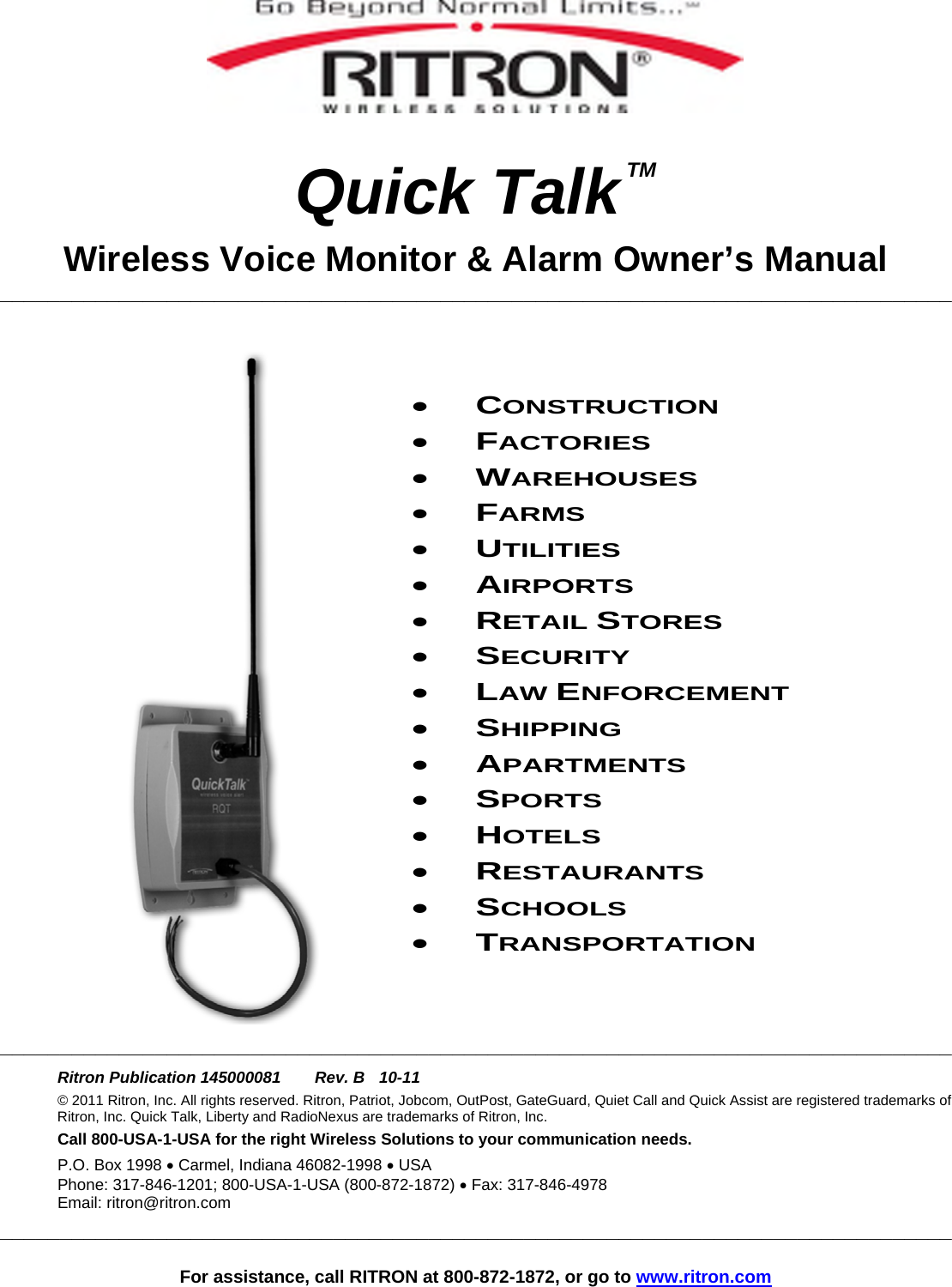
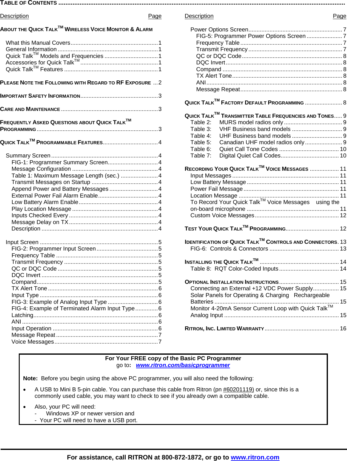
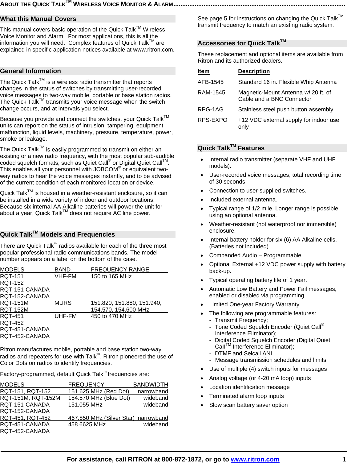
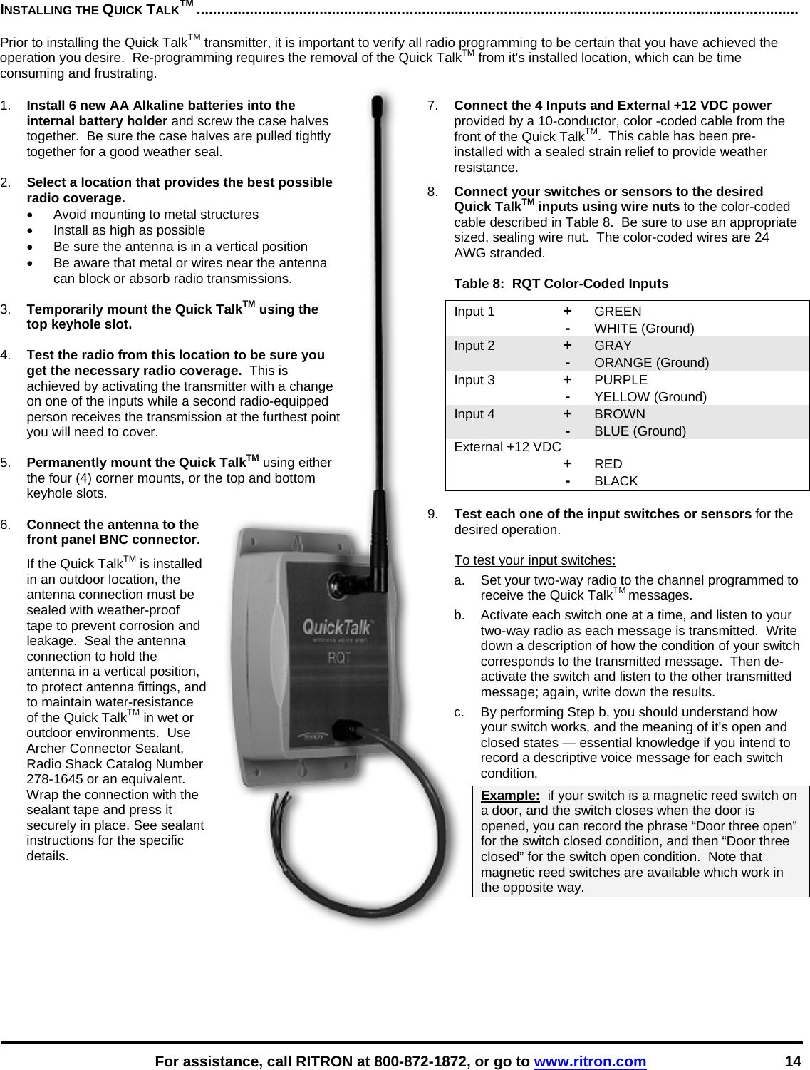
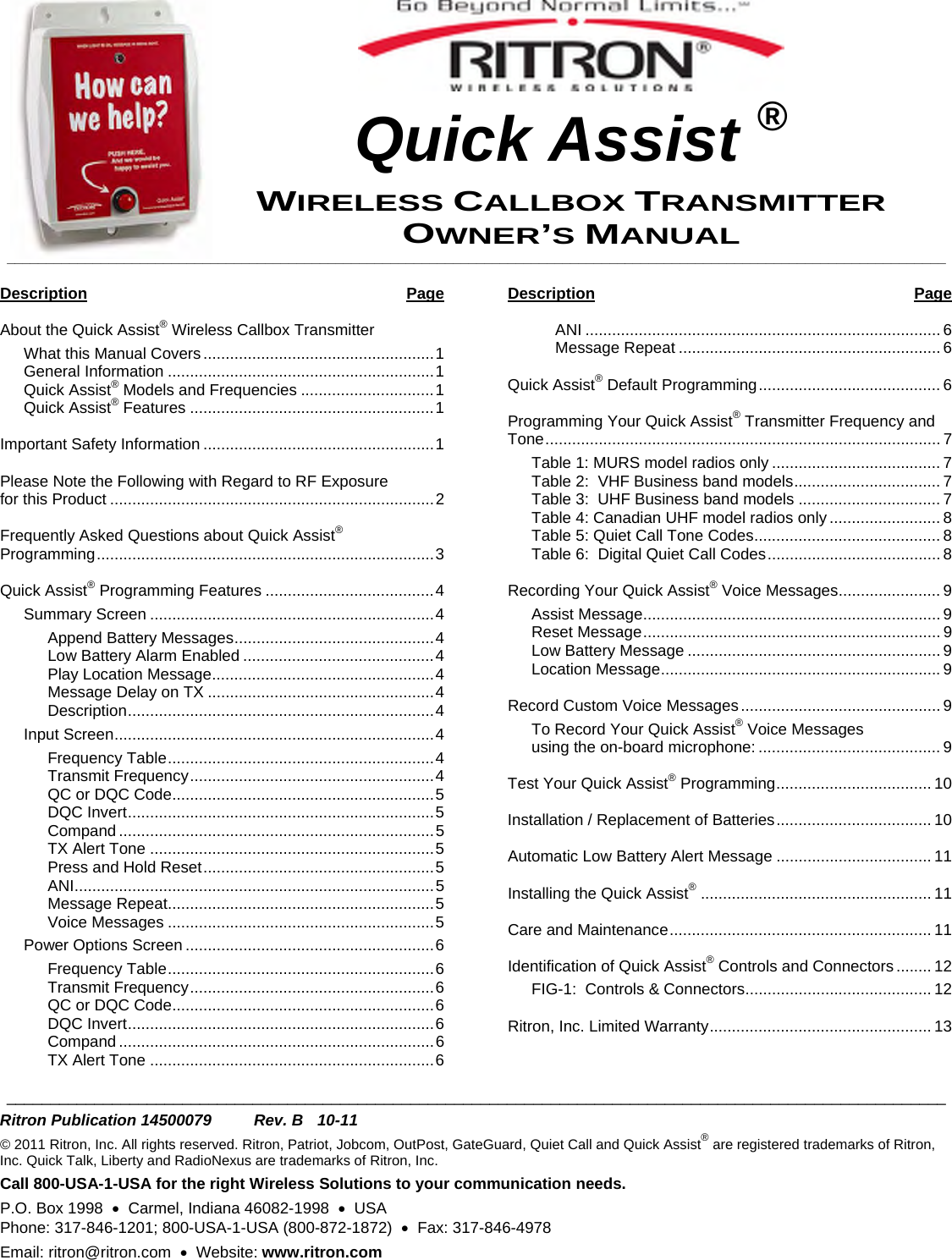
USERS MANUAL
Navigation menu
Upload a User Manual
Namespaces
Wiki Guide
HTML
PDF
Info
Views
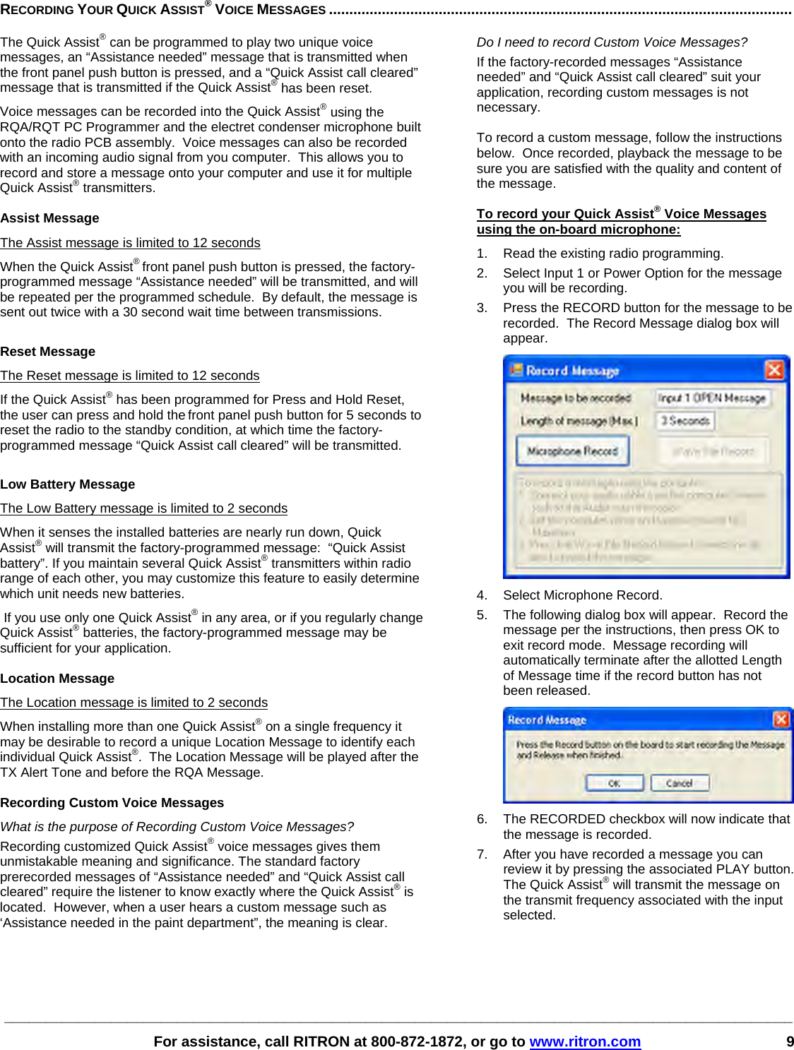
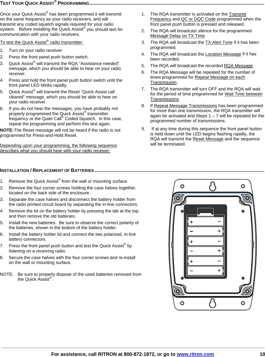
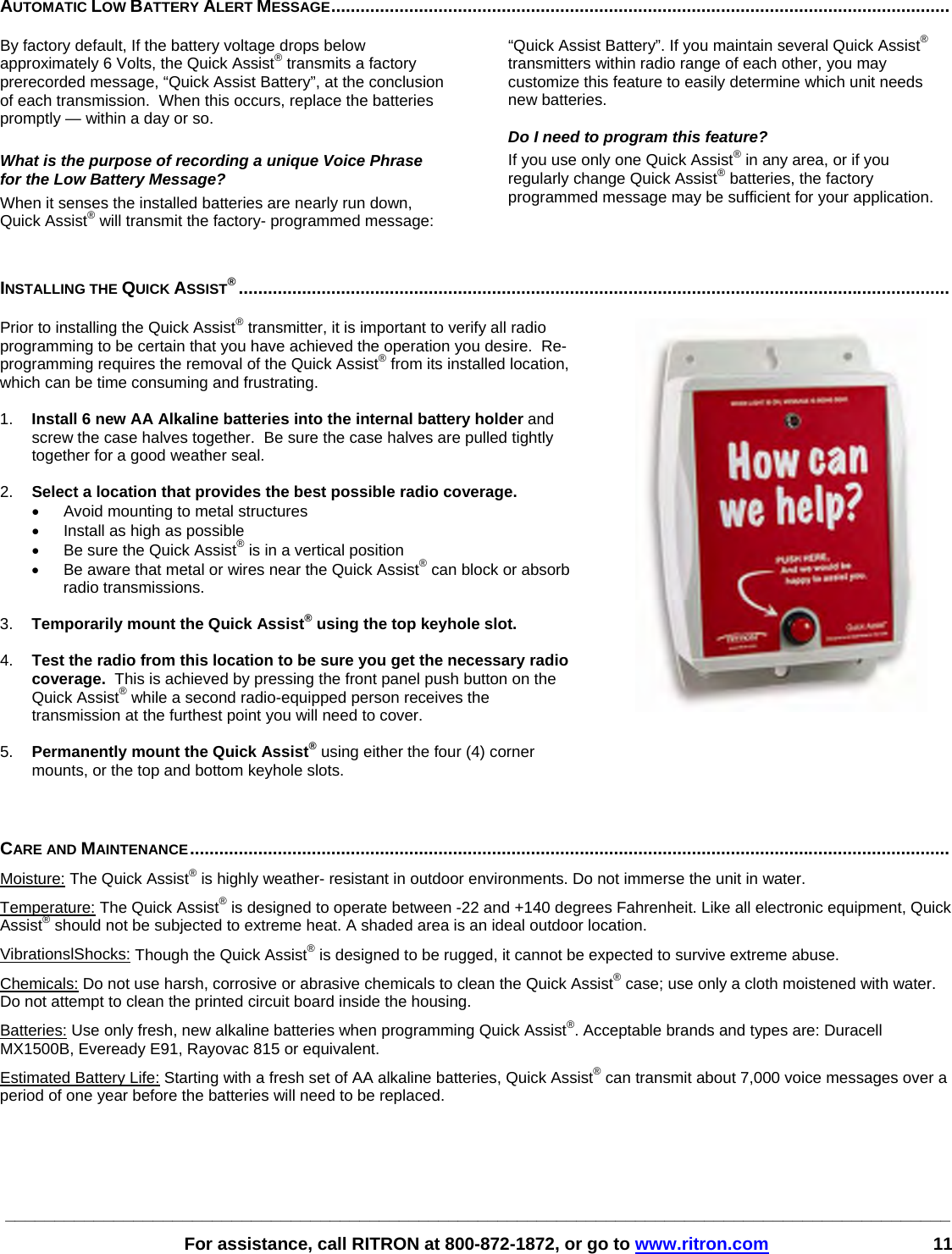
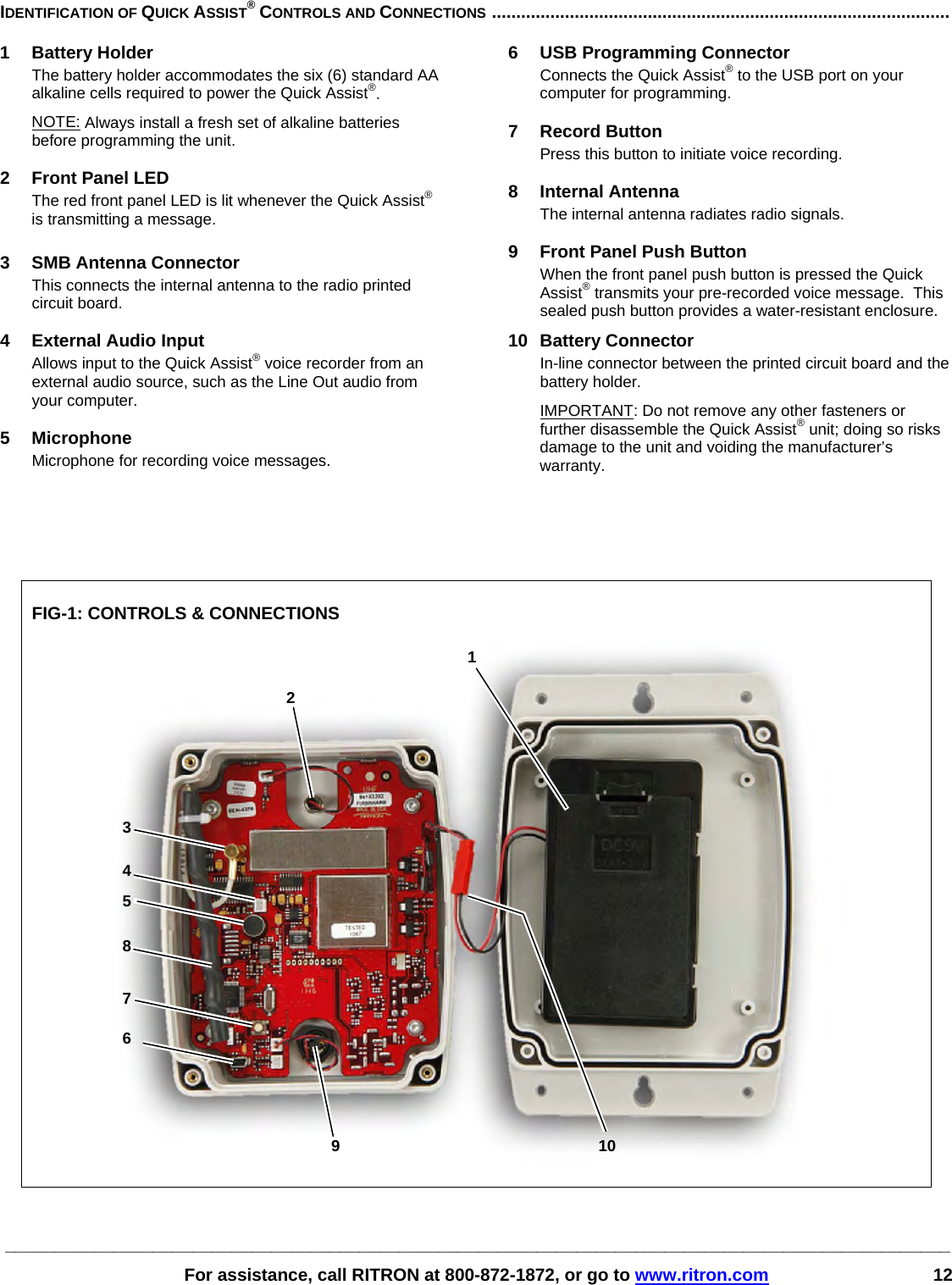
User Manual
Discussion / Help
Navigation