Ritron RIT32-452 UHF-FM VOICE MESSAGE TRANSMITTER User Manual RQT 452 UserMan
Ritron Inc UHF-FM VOICE MESSAGE TRANSMITTER RQT 452 UserMan
Ritron >
Users Manual

RQT-452_UserMan.pdf
TYPE OF EXHIBIT: INSTALLATION AND OPERATING INSTRUCTION MANUAL
FCC PART: 2.1033 (c)(3)
MANUFACTURER: RITRON, INC.
505 West Carmel Drive
Carmel, IN 46032
MODELS: RQA-452, RQT-452
TYPE OF UNIT: UHF-FM Voice Message Transmitter
FCC ID: AIERIT32-452
DATE: October 6, 2011
Included in this exhibit are draft copies of the User Manual for RITRON Models RQT-452 and RQA-452
UHF-FM Voice Message Transmitters.
These manuals provide the end user with installation and operating instructions.
Signed:
Michael A. Pickard - Project Engineer
For assistance, call RITRON at 800-872-1872, or go to www.ritron.com
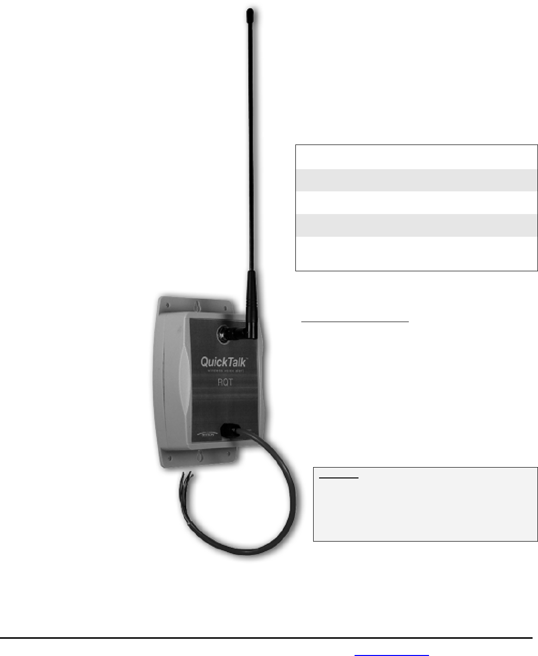
Quick Talk
TM
Wireless Voice Monitor & Alarm Owner’s Manual
________________________________________________________________________________
•
C
ONSTRUCTION
•
F
ACTORIES
•
W
AREHOUSES
•
F
ARMS
•
U
TILITIES
•
A
IRPORTS
•
R
ETAIL
S
TORES
•
S
ECURITY
•
L
AW
E
NFORCEMENT
•
S
HIPPING
•
A
PARTMENTS
•
S
PORTS
•
H
OTELS
•
R
ESTAURANTS
•
S
CHOOLS
•
T
RANSPORTATION
________________________________________________________________________________
Ritron Publication 145000081 Rev. B 10-11
© 2011 Ritron, Inc. All rights reserved. Ritron, Patriot, Jobcom, OutPost, GateGuard, Quiet Call and Quick Assist are registered trademarks of
Ritron, Inc. Quick Talk, Liberty and RadioNexus are trademarks of Ritron, Inc.
Call 800-USA-1-USA for the right Wireless Solutions to your communication needs.
P.O. Box 1998 • Carmel, Indiana 46082-1998 • USA
Phone: 317-846-1201; 800-USA-1-USA (800-872-1872) • Fax: 317-846-4978
Email: ritron@ritron.com
________________________________________________________________________________

For assistance, call RITRON at 800-872-1872, or go to www.ritron.com
TABLE OF CONTENTS ..................................................................................................................................................................
Description Page
ABOUT THE QUICK TALKTM WIRELESS VOICE MONITOR & ALARM
What this Manual Covers......................................................1
General Information ..............................................................1
Quick TalkTM Models and Frequencies .................................1
Accessories for Quick TalkTM ................................................1
Quick TalkTM Features ..........................................................1
PLEASE NOTE THE FOLLOWING WITH REGARD TO RF EXPOSURE ...2
IMPORTANT SAFETY INFORMATION................................................3
CARE AND MAINTENANCE ............................................................3
FREQUENTLY ASKED QUESTIONS ABOUT QUICK TALKTM
PROGRAMMING...........................................................................3
QUICK TALKTM PROGRAMMABLE FEATURES..................................4
Summary Screen..................................................................4
FIG-1: Programmer Summary Screen...............................4
Message Configuration .....................................................4
Table 1: Maximum Message Length (sec.) .......................4
Transmit Messages on Startup .........................................4
Append Power and Battery Messages ..............................4
External Power Fail Alarm Enable.....................................4
Low Battery Alarm Enable.................................................4
Play Location Message .....................................................4
Inputs Checked Every .......................................................4
Message Delay on TX.......................................................4
Description ........................................................................4
Input Screen .........................................................................5
FIG-2: Programmer Input Screen......................................5
Frequency Table ...............................................................5
Transmit Frequency ..........................................................5
QC or DQC Code ..............................................................5
DQC Invert ........................................................................5
Compand...........................................................................5
TX Alert Tone ....................................................................6
Input Type .........................................................................6
FIG-3: Example of Analog Input Type ...............................6
FIG-4: Example of Terminated Alarm Input Type..............6
Latching.............................................................................6
ANI ....................................................................................6
Input Operation .................................................................6
Message Repeat ...............................................................7
Voice Messages................................................................7
Description Page
Power Options Screen.......................................................... 7
FIG-5: Programmer Power Options Screen ...................... 7
Frequency Table............................................................... 7
Transmit Frequency .......................................................... 7
QC or DQC Code.............................................................. 8
DQC Invert........................................................................ 8
Compand .......................................................................... 8
TX Alert Tone.................................................................... 8
ANI.................................................................................... 8
Message Repeat............................................................... 8
QUICK TALKTM FACTORY DEFAULT PROGRAMMING ....................... 8
QUICK TALKTM TRANSMITTER TABLE FREQUENCIES AND TONES..... 9
Table 2: MURS model radios only.................................... 9
Table 3: VHF Business band models ............................... 9
Table 4: UHF Business band models ............................... 9
Table 5: Canadian UHF model radios only....................... 9
Table 6: Quiet Call Tone Codes ..................................... 10
Table 7: Digital Quiet Call Codes.................................... 10
RECORDING YOUR QUICK TALKTM VOICE MESSAGES .................. 11
Input Messages .................................................................. 11
Low Battery Message......................................................... 11
Power Fail Message........................................................... 11
Location Message .............................................................. 11
To Record Your Quick TalkTM Voice Messages using the
on-board microphone ......................................................... 11
Custom Voice Messages.................................................... 12
TEST YOUR QUICK TALKTM PROGRAMMING................................. 12
IDENTIFICATION OF QUICK TALKTM CONTROLS AND CONNECTORS. 13
FIG-6: Controls & Connectors ........................................... 13
INSTALLING THE QUICK TALKTM ................................................. 14
Table 8: RQT Color-Coded Inputs ..................................... 14
OPTIONAL INSTALLATION INSTRUCTIONS..................................... 15
Connecting an External +12 VDC Power Supply................ 15
Solar Panels for Operating & Charging Rechargeable
Batteries ............................................................................. 15
Monitor 4-20mA Sensor Current Loop with Quick TalkTM
Analog Input ....................................................................... 15
RITRON, INC. LIMITED WARRANTY .............................................. 16
For Your FREE copy of the Basic PC Programmer
go to: www.ritron.com/basicprogrammer
Note: Before you begin using the above PC programmer, you will also need the following:
• A USB to Mini B 5-pin cable. You can purchase this cable from Ritron (pn #60201119) or, since this is a
commonly used cable, you may want to check to see if you already own a compatible cable.
• Also, your PC will need:
- Windows XP or newer version and
- Your PC will need to have a USB port.

For assistance, call RITRON at 800-872-1872, or go to www.ritron.com 1
ABOUT THE QUICK TALKTM WIRELESS VOICE MONITOR & ALARM.................................................................................................
What this Manual Covers
This manual covers basic operation of the Quick TalkTM Wireless
Voice Monitor and Alarm. For most applications, this is all the
information you will need. Complex features of Quick TalkTM are
explained in specific application notices available at www.ritron.com.
General Information
The Quick TaIkTM is a wireless radio transmitter that reports
changes in the status of switches by transmitting user-recorded
voice messages to two-way mobile, portable or base station radios.
The Quick TalkTM transmits your voice message when the switch
change occurs, and at intervals you select.
Because you provide and connect the switches, your Quick TalkTM
units can report on the status of intrusion, tampering, equipment
malfunction, liquid levels, machinery, pressure, temperature, power,
smoke or leakage.
The Quick TalkTM is easily programmed to transmit on either an
existing or a new radio frequency, with the most popular sub-audible
coded squelch formats, such as Quiet Call® or Digital Quiet CallTM.
This enables all your personnel with JOBCOM® or equivalent two-
way radios to hear the voice messages instantly, and to be advised
of the current condition of each monitored location or device.
Quick TalkTM is housed in a weather-resistant enclosure, so it can
be installed in a wide variety of indoor and outdoor locations.
Because six internal AA Alkaline batteries will power the unit for
about a year, Quick TalkTM does not require AC line power.
Quick TalkTM Models and Frequencies
There are Quick Talk™ radios available for each of the three most
popular professional radio communications bands. The model
number appears on a label on the bottom of the case.
MODELS BAND FREQUENCY RANGE
RQT-151 VHF-FM 150 to 165 MHz
RQT-152
RQT-151-CANADA
RQT-152-CANADA
RQT-151M MURS 151.820, 151.880, 151.940,
RQT-152M 154.570, 154.600 MHz
RQT-451 UHF-FM 450 to 470 MHz
RQT-452
RQT-451-CANADA
RQT-452-CANADA
Ritron manufactures mobile, portable and base station two-way
radios and repeaters for use with Talk™. Ritron pioneered the use of
Color Dots on radios to identify frequencies.
Factory-programmed, default Quick Talk™ frequencies are:
MODELS FREQUENCY BANDWIDTH
RQT-151, RQT-152 151.625 MHz (Red Dot) narrowband
RQT-151M, RQT-152M 154.570 MHz (Blue Dot) wideband
RQT-151-CANADA 151.055 MHz wideband
RQT-152-CANADA
RQT-451, RQT-452 467.850 MHz (Silver Star) narrowband
RQT-451-CANADA 458.6625 MHz wideband
RQT-452-CANADA
See page 5 for instructions on changing the Quick TalkTM
transmit frequency to match an existing radio system.
Accessories for Quick TalkTM
These replacement and optional items are available from
Ritron and its authorized dealers.
Item Description
AFB-1545 Standard 16 in. Flexible Whip Antenna
RAM-1545 Magnetic-Mount Antenna wI 20 ft. of
Cable and a BNC Connector
RPG-1AG Stainless steel push button assembly
RPS-EXPO +12 VDC external supply for indoor use
only
Quick TalkTM Features
• Internal radio transmitter (separate VHF and UHF
models).
• User-recorded voice messages; total recording time
of 30 seconds.
• Connection to user-supplied switches.
• Included external antenna.
• Typical range of 1/2 mile. Longer range is possible
using an optional antenna.
• Weather-resistant (not waterproof nor immersible)
enclosure.
• Internal battery holder for six (6) AA Alkaline cells.
(Batteries not included)
• Companded Audio – Programmable
• Optional External +12 VDC power supply with battery
back-up.
• Typical operating battery life of 1 year.
• Automatic Low Battery and Power Fail messages,
enabled or disabled via programming.
• Limited One-year Factory Warranty.
• The following are programmable features:
- Transmit Frequency;
- Tone Coded Squelch Encoder (Quiet Call®
Interference Eliminator);
- Digital Coded Squelch Encoder (Digital Quiet
CaIITM Interference Eliminator);
- DTMF and Selcall ANI
- Message transmission schedules and limits.
• Use of multiple (4) switch inputs for messages
• Analog voltage (or 4-20 mA loop) inputs
• Location identification message
• Terminated alarm loop inputs
• Slow scan battery saver option

For assistance, call RITRON at 800-872-1872, or go to www.ritron.com 2
PLEASE NOTE THE FOLLOWING WITH REGARD TO RF EXPOSURE FOR THIS PRODUCT....................................................................
EXPOSURE TO RADIO FREQUENCY ENERGY:
RQT-151, RQT-151M, RQT-451, RQT-451-CANADA,
RQT-152, RQT-152M, RQT-452, RQT-452-CANADA
This product generates radio frequency (RF) energy when the
state of any of the four inputs has been changed. This product
has been evaluated for compliance with the maximum
permissible exposure limits for RF energy at the maximum
power rating of the unit when using antennas available from
RITRON.
For both the AFB-1545 and the standard internal antennas, at
the 20 cm (7.9 inches) minimum expected separation distance
and greater, the maximum RF exposure is well below the
General Population/Uncontrolled limits. Antennas other than
those available from RITRON have not been tested for
compliance and may or may not meet the exposure limits at
the distances given. Higher gain antennas are capable of
generating higher fields in the strongest part of their field and
would, therefore, require a greater separation from the
antenna. This product is not to be used by the general public
in an uncontrolled environment unless compliance with the
Uncontrolled/General Population limits for RF exposure can be
assured.
To limit exposure to RF energy to levels below the limit, please
observe the following:
• Use only the antenna(s) available from RITRON for these
models. DO NOT operate the radio without an antenna.
• DO NOT activate the transmitter when not actually wishing
to transmit. These radios transmit recorded messages of a
pre-determined length to prevent continuous transmit times.
• When transmitting, make certain that the distance limits for
the particular model in use are observed.
• DO NOT allow children to operate the radio.
When used as directed, this series of radios is designed to
comply with the FCC’s RF exposure limits for
“Uncontrolled/General Population”. In addition, they are
designed to comply with the following Standards and
Guidelines:
• United States Federal Communications Commission, Code
of Federal Regulations; 47 CFR §§ 2 sub-part J.
• American National Standards Institute (ANSI) / Institute of
Electrical and Electronic Engineers (IEEE) C95. 1-1992.
• Institute of Electrical and Electronic Engineers (IEEE)
C95.1-1999 Edition.
Copyright Telecommunications Industry Association
LISEZ S'IL VOUS PLAÎT LA DÉCLARATION SUIVANTE DE L'EXPOSITION RF POUR CE PRODUIT. ..........................................................
RQT-151, RQT-151M, RQT-451, RQT-451-CANADA,
RQT-152, RQT-152M, RQT-452, RQT-452-CANADA
Ce produit génère énergie radiofréquence (RF) lorsque le
statut de l'un des quatre éléments a été modifié. Ce produit a
été évalué pour le respect des limites de l'exposition maximale
admissible pour l'énergie RF à la cote de puissance maximale
de l'émetteur lorsque vous utilisez des antennes RITRON.
Lorsque vous utilisez l'AFB-1545 ou les antennes internes
standards, à la 20 cm (7,9 pouces) minimum prévu à distance
de séparation et au-delà, l'exposition RF maximale est
inférieure à la Population générale / Uncontrolled limite.
Antennes non-RITRON n'ont pas été testés pour la conformité
et peuvent ou peuvent ne pas satisfaire les limites d'exposition
à des distances donnés. Antennes de gains plus élevés sont
capables de générer des champs plus élevés dans la partie
plus forte de leur domaine et nécessiteraient donc une plus
grande séparation de l'antenne. Ce produit ne doit ne pas être
utilisé par le public en général dans un environnement non
contrôlé, à moins que la conformité avec la Uncontrolled / les
limites de l'ensemble de la Population pour l'exposition RF
peuvent être assurés.
Pour limiter l'exposition à l'énergie RF à des concentrations
inférieures à la limite, veuillez observer ce qui suit :
• Utilisez uniquement des antennes RITRON pour ces
modèles. NE fonctionnent pas sans une antenne de la
radio.
• N'utilisez pas l'émetteur lorsque vous ne souhaitez pas
transmettre. Ces radios transmettent enregistré des
messages d'une durée prédéterminée pour empêcher
continu transmettent times.
• Lors de la transmission, s'assurer que les limites de
distance pour le modèle particulier en usage sont
observées.
• NE laissez pas les enfants pour l'exploitation de la radio.
Lorsqu'il est utilisé conformément aux directives, cette série de
radios est conçue pour respecter les limites d'exposition RF
pour « Incontrôlée / Population générale ». En outre, ils sont
conçus pour respecter les normes et lignes directrices
suivantes :
• United States Federal Communications Commission, Code
of Federal Regulations; 47 CFR §§ 2 sub-part J.
• American National Standards Institute (ANSI) / Institute of
Electrical and Electronic Engineers (IEEE) C95. 1-1992.
• Institute of Electrical and Electronic Engineers (IEEE)
C95.1-1999 Edition.
Copyright Telecommunications Industry Association

For assistance, call RITRON at 800-872-1872, or go to www.ritron.com 3
IMPORTANT SAFETY INFORMATION...............................................................................................................................................
NOTICE The Quick TalkTM should not be used to report conditions relating to the safety of life or property.
To reduce the risk of fire, electric shock or personal injury, follow these basic safety instructions when using this unit.
1. Read and follow all instructions.
2. Remove power from the unit before cleaning. Do not use liquid or aerosol cleaners.
3. Use only Ritron approved power sources for the unit.
4. During thunderstorms, avoid contact with this unit and any external antenna system or wiring.
5. The Quick TalkTM switch and external power inputs are connected internally to the antenna connector. If the Quick TalkTM switch or
power supply terminals contact high voltage, a hazardous condition may exist in that contacting the antenna could prove injurious
or even fatal.
6. In general, the switches you connect to the Quick TalkTM are to be independent dry contact switches, and not part of any other
“live” electrical circuit
7. If you are unsure whether your installation will be safe, contact an experienced electrician or electronics technician.
CARE AND MAINTENANCE............................................................................................................................................................
Moisture: When the antenna sealant and power cable
recommendations are followed, the Quick TalkTM is highly
weather-resistant in outdoor environments. Do not immerse the
unit in water.
Temperature: The Quick TalkTM is designed to operate
between -22 and +140 degrees Fahrenheit. Like all electronic
equipment, Quick TalkTM should not be subjected to extreme
heat. A shaded area is an ideal outdoor location.
Vibrations/Shocks: Though the Quick TalkTM is designed to be
rugged, it cannot be expected to survive extreme abuse.
Chemicals: Do not use harsh, corrosive or abrasive chemicals
to clean the Quick TalkTM case; use only a cloth moistened with
water. Do not attempt to clean the printed circuit board inside
the housing.
Batteries: Use only fresh, new alkaline batteries when
programming Quick TalkTM. Acceptable brands and types are:
Duracell MX1500B, Eveready E91, Rayovac 815 or equivalent.
Estimated Battery Life: Starting with a fresh set of AA alkaline
batteries, Quick Talk TM can transmit about 7,000 voice
messages over a period of one year before the batteries will
need to be replaced.
FREQUENTLY ASKED QUESTIONS ABOUT QUICK TALKTM PROGRAMMING......................................................................................
Do I have to program my Quick TalkTM?
You may not need to program your Quick TalkTM at all. If you
purchased a Quick TalkTM that is factory-programmed to your
radio system frequency (check the Color Dots on your radios
and the Quick TalkTM), and you do not use a form of Quiet Call
coded squelch, you can connect your switch to the color-coded
“Input #1” wires on the hook-up cable, install the batteries, and
start using Quick TalkTM. The factory default voice messages
are “Switch 1 Open” and “Switch 1 Closed”. Otherwise, read
this manual, and then program your Quick TalkTM.
Do I need to program every feature?
In many cases, no. The factory pre-programmed settings,
explained in the instructions, may meet many of your needs.
How do I program my Quick TalkTM?
Quick TalkTM is programmed using RITRON programming
software and a PC computer.
What if I don’t find what I need in this manual?
Call Ritron (800-872-1872): we will be glad to help you. For
most applications, this manual should cover everything you will
need to know.
Will it harm the Quick TalkTM if I program it improperly?
No; however, you may need to erase all programming and start
over. Feel free to experiment with the various features and
possible configurations.
Can my settings or messages get lost or erased if the
battery runs down, or if my Quick TalkTM is disconnected?
No. The settings and voice messages you enter are stored in
special electronic memory devices in the Quick TalkTM that do
not require power to hold the information. This means that if
the batteries run down or if you remove them, you will not need
to reprogram the unit. All your settings and messages will be
there for you when you install fresh batteries.
What if I need more range?
To increase the range of your Quick TalkTM transmissions, we
suggest you first relocate the unit. Depending on the type of
switch and wiring, you may use several hundred feet of wiring
to connect the switch — this allows installation of the Quick
TalkTM and it’s attached antenna at an unobstructed and
elevated position for the best range.
Also, Ritron offers several optional “high gain” antennas. Ritron
also offers a radio repeater to increase the range not only for
your Quick TalkTM, but also for your entire radio system.
For assistance, call RITRON at 800-872-1872, or go to www.ritron.com 4
QUICK TALKTM PROGRAMMABLE FEATURES.................................................................................................................................
The Quick TalkTM features four (4) separate inputs that can each be programmed with unique voice messages and attributes. All
programming is accomplished with the RITRON RQA/RQT PC Programmer software available at www.ritron.com, and a standard USB
Type A to Mini-B cable for interconnection of the PC computer to the Quick TalkTM.
The programmer software requires Window® XP or newer, and a PC computer with a USB port.
Summary Screen
After reading the radio programming, a summary screen will appear with a
tabulated display of the input programming. Double-click on any input
column to program that input’s attributes. Radio-wide features are
programmed from the Summary Screen.
FIG-1: Programmer Summary Screen
Message Configuration
Programming the Message Configuration must be done before recording any
of the voice messages. This allocates the available time for each message.
Changing the Message Configuration will erase existing messages, requiring
you to re-record all input messages.
Number of Inputs – This sets the number of inputs you will be using.
Inputs used will always start with number 1 and progress sequentially as
you add inputs.
Example: If you program the RQT for 2 inputs, Input 1 and Input 2 will
be available, it cannot be Input 1 and Input 3.
Play Single Message Only – Setting an input for a single message
doubles the available message time. The single message can be either
the Open or Closed message.
Table 1: Maximum Message Length (sec.)
Number Single Both
of Inputs Message Messages
1 input 24 sec. 12 sec.
2 inputs 12 sec. 6 sec.
3 inputs 8 sec. 4 sec.
4 inputs 6 sec. 3 sec.
Transmit Messages on Startup
If selected, Input status messages are
transmitted when the RQT is powered on. This
may be helpful in the event of a power outage.
Append Power and Battery Messages
If selected, Power Fail and Low Battery
messages will play at the conclusion of any
Input status message, as well as on the
programmed schedule.
External Power Fail Alarm Enable
If selected, a Power Fail message is transmitted
any time External Power supply drops below
+12 VDC.
Low Battery Alarm Enable
If selected, a Low Battery message is
transmitted when the internal batteries are in
need of replacement.
Play Location Message
If selected, the RQT will transmit a recorded
Location message immediately prior to any Input
status message, Low Battery message, or
Power Fail message.
Inputs Checked Every:
RQT checks Input status every 250mS by
default, but can be set to check every one
second to extend battery life.
Message Delay on TX
This sets a time delay between turning on the
RQT transmitter and playing any messages, or
ANI strings.
Description
Enter a brief description (35 characters or less)
of the RQT use, location, customer, etc. This
can be useful when reading out the Quick TalkTM
programming at a later date, or when saving a
programming profile for use with other radios.
For assistance, call RITRON at 800-872-1872, or go to www.ritron.com 5
QUICK TALKTM PROGRAMMABLE FEATURES.................................................................................................................................
Input Screen
The Input Screen is used to uniquely program the behavior of each input.
FIG-2: Programmer Input Screen
Frequency Table
To match other RITRON radios, the owner can select from a table of transmit
frequencies. Simply “read-out” the Frequency Code of your RITRON
portable, mobile or base radio and enter the same code when programming
the Quick TalkTM. Note that all RQT-151 and RQT-451 table frequencies
operate in narrow band mode (12.5 kHz).
Transmit Frequency
Once you have selected a code from the Frequency Table the actual transmit
frequency will appear here. If your operating frequency does not appear on
the Frequency Table list, a licensed radio service technician will be able to
enter other frequencies within the radio’s operating band.
To identify your assigned frequency:
• Read-out the Frequency Code of the RITRON radio you intend to use with
the Quick TalkTM.
• Check for a corresponding color dot on the radio you intend to use with
the Quick TalkTM.
• Locate a label identifying the receiver frequency in megahertz (MHz).
• Your assigned frequency is shown on your FCC Station License.
• Call your radio dealer or Ritron for help if you cannot determine your
radio’s receiver frequency.
• The original factory-programmed transmitter frequency of your Quick
TalkTM is marked on the outside of the shipping box.
QC or DQC Code
Select from a list of QC and DQC Codes to transmit subaudible squelch
tones for interference elimination.
The Quick TalkTM radio transmitter is compatible with two standard
communications industry sub-audible signaling formats: QC (Quiet Call®
Interference Eliminator), and DQC (Digital Quiet CallTM Interference
Eliminator). Both Quiet Call formats unlock receivers programmed to require
these codes -- they screen out interference from
other radio systems operating on your transmit
frequency.
QC Quiet Call® is Ritron’s trade name for what
the communications industry calls sub-audible
(below the range of human hearing) tone
squelch, or CTCSS (Continuous Tone Coded
Subaudible Squelch).
DQC Digital Quiet CallTM is Ritron’s digital coded
squelch, and works the same as QC, except it is
a digital code that is transmitted with the voice
messages.
To identify your QC or DQC tone:
• Read-out the Tone Code of the RITRON
radio you intend to use with the Quick
TalkTM.
• Refer to your radio manual.
• Contact your radio dealer or Ritron if you are
unsure about this issue.
DQC Invert
The DQC Digital Quiet CallTM code can be
inverted for systems that require inversion.
Compand
Some two-way radios have a feature referred to
as “companding”. It is a way of eliminating
background hiss or noise, making the radio
sound clearer. “Companding” is a combination of
audio “compression” in the transmitter and audio
“expanding” in the receiver. The Quick TalkTM
can be programmed for audio compression. To
determine if your existing 2-way radios are using
the Companding feature, you can check the
radio’s User Manual, contact your radio dealer,
or call Ritron for help.
If you are unable to determine if your portable
radio uses the companding feature, we suggest
the following:
1. Leave the radio in the factory default setting
with no companding.
2. Activate the transmitter of the Quick TalkTM
and listen to the message from your
portable radio. If the received audio is
acceptable, you should not need to set the
Quick TalkTM for companding.
TX Alert Tone
By default, the RQT will transmit an alert tone
before each voice message transmission. This
feature can be disabled via the PC programmer.
For assistance, call RITRON at 800-872-1872, or go to www.ritron.com 6
QUICK TALKTM PROGRAMMABLE FEATURES.................................................................................................................................
Input Type
Each input can be programmed for one of the three (3) basic types
of Input operation.
Contact Closure – Is used when a switch closure is connected
to the input.
Analog Input – Voltages above the High Analog Setpoint cause
the Input OPEN message to transmit. The hysteresis voltage
determines how much below the High Analog Setpoint the
voltage must drop before it is no longer considered in the OPEN
condition. Voltages below the Low Analog Setpoint cause the
Input CLOSED message to transmit, with the hysteresis voltage
determining how much above the Low Analog Setpoint the
voltage must rise before it is no longer considered in the
CLOSED condition. If the input is within the middle “dead zone”
no message will be sent.
FIG-3: Example of Analog Input Type
Terminated Alarm Input - This mode is useful in security alarm
applications, where the “Secure” (Good) condition is a range of
voltages. Any voltage above or below this range represents an
“Alarm” (Bad) condition.
The “Secure” condition is the range of voltage between the High
and Low Analog Setpoints. The input OPEN message is
activated in this range. Voltage above High Analog Setpoint, or
below Low Analog Setpoint activates the input CLOSED
message. Once the input is in the “Alarm” condition, the
hysteresis voltage determines how much below the High Analog
Setpoint or above the Low Analog Setpoint the voltage must go
before it is no longer considered in the CLOSED condition.
FIG-4: Example of Terminated Alarm Input Type
Analog Setpoints - The HIGH and LOW analog
setpoints are used with Analog Input mode or
Terminated Alarm Input mode, and can be programmed
to any DC voltage between 0-5 VDC. The Hysteresis
voltage is an offset applied to the HIGH and LOW Analog
Setpoints once they have been exceeded. Analog
Setpoints have no effect when the Input is set to Contact
Closure mode.
Latching
Use the Quick TalkTM Latching Input mode if repeated
transmissions are desired with a momentary switch (i.e. a
push-button). The latching effect maintains message
repeats after the momentary switch change has ended.
Latching can only apply to one input condition, open or
closed.
Example: To use a Quick TalkTM in a paint department,
you want it to re-transmit an “Assistance Needed” message
several times after a “Press for Help” push-button is
pressed. With the Quick TalkTM set to Latching Input mode,
release of the push-button is ignored and the message is
re-transmitted as scheduled.
Press and Hold Reset - With the Quick TalkTM
programmed for latching mode operation it’s often
desirable to repeat the “Assistance message” without
limitation until the call has been answered. With Press
and Hold Reset enabled the push button can be held
down for 5 seconds to reset the Quick TalkTM to the
standby condition.
Example: To use a Quick TalkTM in a paint department,
you want it to re-transmit a message several times after a
“Press for Help” push-button is pressed. With the Quick
TalkTM set for Press and Hold Reset an employee can
terminate the message transmissions, and in the process
send a “Call answered” message.
ANI
The Input Open and Input Closed conditions can each be
programmed with a unique 1-9 digit DTMF or 3-7 digit
Selcall ANI string. The ANI will be transmitted immediately
prior to the Alert Tone and Input message. To program an
ANI string, select Selcall or DTMF and enter the string in
the value field.
Input Operation
Normal – operation transmits a message each time a
changed condition is detected.
Dwell Mode - is an option specifying that the switch must
remain in it’s changed condition for the programmed
dwell time before generating a message for the changed
condition.
Example: A sensor is used to detect a car in a “No
Parking” zone. Since it is undesirable for a message to
be generated by normal traffic through the “No Parking”
zone, a five-minute Dwell is used. Only if the sensor is
activated for a full five minutes will the “car illegally
parked” message be transmitted.
For assistance, call RITRON at 800-872-1872, or go to www.ritron.com 7
QUICK TALKTM PROGRAMMABLE FEATURES.................................................................................................................................
Holdoff Mode - option transmits messages immediately upon
a change of switch condition, and will hold off a message
indicating further change for the programmed holdoff time.
Example: A Quick TalkTM is used as a gate doorbell. It is
practical for the message to be transmitted immediately, and
also desirable to have a one-minute holdoff before the same
message is re-sent, even if the button is pushed repeatedly.
Dwell / Holdoff Time – specifies the dwell time or holdoff time
described above. This time is programmed independently for
the OPEN and CLOSED conditions.
Message Repeat
Number of Message Transmissions
You can set a limit to the number of times the message will be
transmitted at a scheduled interval.
Time Between Transmissions
This sets the amount of time the Quick TalkTM will wait between
repeated transmissions. You can program a different Wait
Time for the open condition, and for the closed condition of
your switch.
The Quick TalkTM is set at the factory to transmit switch status
messages only when they change.
Example: The switch status message for switch open is
“Pump motor temperature OK”. You may schedule the Quick
TalkTM to transmit this message once every two hours; this
way, you know the Quick TalkTM is operating properly.
If the corresponding switch status message for switch closed is
“Pump Motor Over Temperature”, you may schedule the Quick
TalkTM to broadcast this message every two minutes, so the
situation would receive prompt attention.
Example: Suppose you have a vehicle detection switch that
closes when it detects a vehicle at the delivery door of your
building. Your recorded message might then be “Vehicle at
Delivery Door”. You may want this message to be transmitted
every two minutes for approximately a quarter hour after a
vehicle is detected, then to stop transmitting until the vehicle is
moved. In this case, you would program the Time Between
Transmissions for two minutes, and set the Number of
Message Transmissions to 8.
When a vehicle arrives, the switch closes and the message is
transmitted every 2 minutes until it has been sent 8 times over
a span of 16 minutes, unless the vehicle leaves before 16
minutes has lapsed. In this case, the switch opens and the
message ceases when the vehicle is moved.
When another vehicle arrives, the Quick TalkTM again transmits
the message every two minutes for about a quarter of an hour,
or until the vehicle leaves.
Repeat Message on each transmission
Your recorded voice message can be programmed to repeat
from one time to nine times on each Quick TalkTM radio
transmission. Urgent messages may require more phrase
repeats.
Example: You recorded the message “Pump Motor Hot”, and
then programmed the Quick TalkTM to repeat the phrase two
(2) times in each transmission. In this case, activating the
switch results in the Quick TalkTM transmitting: “...beep. Pump
motor hot. Pump motor hot....” The beginning beep can be
added to attract attention to Quick TalkTM transmissions.
Voice Messages
The Input Open and Input Closed messages are recorded via
the Input Screen. Refer to the Recording Your Quick Voice
TalkTM Messages section of this manual for instructions on
recording voice messages. The Recorded box indicates
whether or not a message has been recorded. The Maximum
Record Time for each message is also indicated. This time is
determined by the number of inputs programmed on the
Summary Screen.
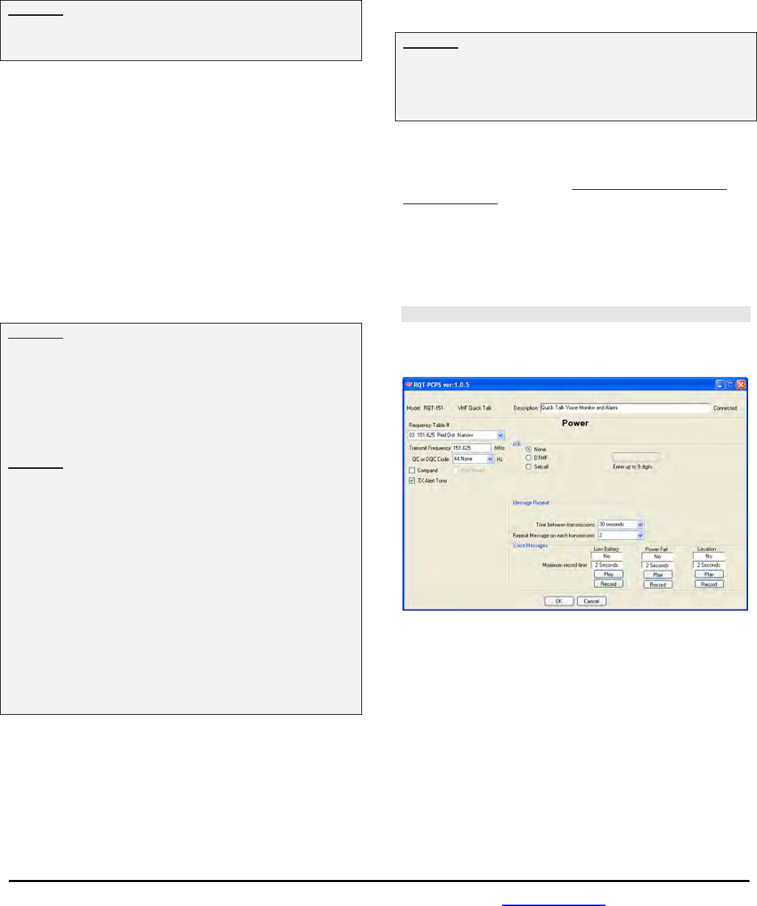
Power Options Screen
Power Fail and Low Battery Alert messages can be
programmed for unique frequencies, tones, and Voice
messages.
FIG-5: Programmer Power Options Screen
Frequency Table #
To match other RITRON radios, the owner can select from a
table of transmit frequencies. Simply “read-out” the Frequency
Code of your RITRON portable, mobile or base radio and enter
the same code when programming the Quick TalkTM.
Transmit Frequency
Once you have selected a Frequency Code the actual transmit
frequency will appear here. If your operating frequency does
not appear on the Frequency Code list, a licensed radio
service technician will be able to enter other frequencies within
the radio’s operating band.

For assistance, call RITRON at 800-872-1872, or go to www.ritron.com 8
QUICK TALKTM PROGRAMMABLE FEATURES.................................................................................................................................
QC or DQC Code
Select from a list of QC and DQC Codes to transmit subaudible
squelch tones for interference elimination.
DQC Invert
The DQC Digital Quiet CallTM code can be inverted for systems
that require inversion.
Compand
Set Compand for compression of the transmit audio.
“Companding” is a combination of audio “compression” in the
transmitter and audio “expanding” in the receiver. To determine
if your existing 2-way radios are using the Companding
feature, you can check the radio’s User Manual, contact your
radio dealer, or call Ritron for help.
TX Alert Tone
The RQT can transmit an alert tone before each voice
message transmission.
ANI
Power Alerts messages can be programmed with a unique 9
digit DTMF or 3-7 digit Selcall ANI string. The ANI will be
transmitted immediately prior to the Alert Tone and Power Alert
message. To program an ANI string, select Selcall or DTMF
and enter the string in the value field.
Message Repeat
Time between transmissions
This sets the amount of time the Quick TalkTM will wait before
re-transmitting a Power Alert message. For battery powered
operation this time will likely be 1 hour or more.
Repeat Message on each transmission
Your recorded voice message can be programmed to repeat
from one time to nine times on each Quick TalkTM radio
transmission, depending on how you program this feature.
Urgent messages may require more phrase repeats.
Voice Messages
Refer to the Recording Your Quick TalkTM Voice Messages
section of this manual for instructions on recording voice
messages.
QUICK TALKTM FACTORY DEFAULT PROGRAMMING ......................................................................................................................
TX Frequency (all inputs)
RQT-151, -152 03 151.625 MHz NB
RQT-151M, -152M 02 154.570 MHz WB
RQT-151-CANADA 01 151.055 MHz WB
RQT-451, -452 26 467.850 MHz NB
RQT-451-CANADA 01 458.6625 MHz WB
QC/DQC Code (all inputs) 44 No Tone
DQC Invert No
Compand No
Input Type Contact Closure
Analog Setpoints High 3.6 VDC
Low 1.7 VDC
Input Operation Normal
Latching Input Mode No
Dwell/Holdoff Time Open/High none
Closed/Low none
Number of Inputs Inputs 1 and 2
TX Alert Tone Yes
Power Strobe Time 250 mS
Append Power Messages Yes
Low Battery Message Yes
Power Fail Message No
Play Location Message No
Message Delay on TX 1 sec.
Recorded Messages
Input 1 Open/High “Switch 1 open”
Input 1 Closed/Low “Switch 1 closed”
Input 2 Open/High “Switch 2 open”
Input 2 Closed/Low “Switch 2 closed”
Power Fail “Quick Talk power fail”
Low Battery “Quick Talk battery”
Number of Times Recorded Message is repeated on each
Transmission
Inputs 1-4 Open/High One time
Inputs 1-4 Closed/Low One time
Power Alert One time
Number of Times the Transmission is sent
Inputs 1-4 Open/High No repeat
Inputs 1-4 Closed/Low No repeat
Power Fail Forever
Wait Time between Transmissions
Inputs 1-4 Open/High On change only
Inputs 1-4 Closed/Low On change only
Power Alert 1 Hour
For assistance, call RITRON at 800-872-1872, or go to www.ritron.com 9
QUICK TALKTM TRANSMITTER TABLE FREQUENCIES AND TONES...................................................................................................
The Quick TalkTM transmitter operates exclusively on a 12.5 kHz narrow band channel bandwidth. Many of the Frequency Table Codes
programmed in your compatible Ritron radios are for 25 kHz wide band channels. If these codes are selected when programming your
Quick TalkTM radio, the radio will operate at a 12.5 kHz narrow band channel bandwidth. This allows you to use your Quick TalkTM with
all of your existing radios.
The RQT-151M and RQT-152M MURS model radios can only be programmed to the codes listed on Table 2 below. VHF Business
band models can be programmed to the codes listed on Table 3 below, or can be programmed to any valid licensed frequency between
150-165 MHz EXCEPT the frequencies listed on MURS Table 2 below.
TABLE 2: MURS model radios only (US)
Frequency Channel
Code (MHz) Color Dot Bandwidth
01 154.600 Green Dot 25 kHz
02 154.570 Blue Dot 25 kHz
19 151.820 MURS 12.5 kHz
20 151.880 MURS 12.5 kHz
21 151.940 MURS 12.5 kHz
22 154.600 MURS 12.5 kHz
23 154.570 MURS 12.5 kHz
TABLE 3: VHF Business band models (US)
Frequency Channel
Code (MHz) Color Dot Bandwidth
03 151.625 Red Dot 12.5 kHz
04 151.955 Purple Dot 12.5 kHz
05 151.925 12.5 kHz
06 154.540 12.5 kHz
07 154.515 12.5 kHz
08 154.655 12.5 kHz
09 151.685 12.5 kHz
10 151.715 12.5 kHz
11 151.775 12.5 kHz
12 151.805 12.5 kHz
13 151.835 12.5 kHz
14 151.895 12.5 kHz
15 154.490 12.5 kHz
16 151.655 12.5 kHz
17 151.745 12.5 kHz
18 151.865 12.5 kHz
24 151.700 12.5 kHz
25 151.760 12.5 kHz
26 152.700 12.5 kHz
TABLE 4: UHF Business band models (US)
Frequency Channel
Code (MHz) Color Dot Bandwidth
01 467.7625 J 12.5 kHz
02 467.8125 K 12.5 kHz
03 464.5500 Yellow Dot 12.5 kHz
04 464.5000 Brown Dot 12.5 kHz
05 467.8500 Silver Star 12.5 kHz
06 467.8750 Gold Star 12.5 kHz
07 467.9000 Red Star 12.5 kHz
08 467.9250 Blue Star 12.5 kHz
09 469.2625 12.5 kHz
10 462.5750 White Dot 12.5 kHz
11 462.6250 Black Dot 12.5 kHz
12 462.6750 Orange Dot 12.5 kHz
13 464.3250 12.5 kHz
14 464.8250 12.5 kHz
15 469.5000 12.5 kHz
16 469.5500 12.5 kHz
17 463.2625 12.5 kHz
18 464.9125 12.5 kHz
19 464.6000 12.5 kHz
20 464.7000 12.5 kHz
TABLE 4: UHF Business band models (US) cont.
Frequency Channel
Code (MHz) Color Dot Bandwidth
21 462.7250 12.5 kHz
22 464.5000 Brown Dot 12.5 kHz
23 464.5500 Yellow Dot 12.5 kHz
24 467.7625 J 12.5 kHz
25 467.8125 K 12.5 kHz
26 467.8500 Silver Star 12.5 kHz
27 467.8750 Gold Star 12.5 kHz
28 467.9000 Red Star 12.5 kHz
29 467.9250 Blue Star 12.5 kHz
30 461.0375 12.5 kHz
31 461.0625 12.5 kHz
32 461.0875 12.5 kHz
33 461.1125 12.5 kHz
34 461.1375 12.5 kHz
35 461.1625 12.5 kHz
36 461.1875 12.5 kHz
37 461.2125 12.5 kHz
38 461.2375 12.5 kHz
39 461.2625 12.5 kHz
40 461.2875 12.5 kHz
41 461.3125 12.5 kHz
42 461.3375 12.5 kHz
43 461.3625 12.5 kHz
44 462.7625 12.5 kHz
45 462.7875 12.5 kHz
46 462.8125 12.5 kHz
47 462.8375 12.5 kHz
48 462.8625 12.5 kHz
49 462.8875 12.5 kHz
50 462.9125 12.5 kHz
51 464.4875 12.5 kHz
52 464.5125 12.5 kHz
53 464.5375 12.5 kHz
54 464.5625 12.5 kHz
55 466.0375 12.5 kHz
56 466.0625 12.5 kHz
57 466.0875 12.5 kHz
58 466.1125 12.5 kHz
59 466.1375 12.5 kHz
60 466.1625 12.5 kHz
61 466.1875 12.5 kHz
62 466.2125 12.5 kHz
63 466.2375 12.5 kHz
64 466.2625 12.5 kHz
65 466.2875 12.5 kHz
66 466.3125 12.5 kHz
67 466.3375 12.5 kHz
68 466.3625 12.5 kHz
69 467.7875 12.5 kHz
70 467.8375 12.5 kHz
71 467.8625 12.5 kHz
72 467.8875 12.5 kHz
73 467.9125 12.5 kHz
74 469.4875 12.5 kHz
75 469.5125 12.5 kHz
76 469.5375 12.5 kHz
77 469.5625 12.5 kHz
For assistance, call RITRON at 800-872-1872, or go to www.ritron.com 10
QUICK TALKTM TRANSMITTER TABLE FREQUENCIES AND TONES...................................................................................................
TABLE 5: Canadian UHF model radios only
Code Frequency (MHz) Color Dot Channel Bandwidth
01 458.6625 25 kHz
02 469.2625 25 kHz
TABLE 6: Quiet Call Tone Codes
Code Frequency
00 None
01 67.0
02 71.9
03 74.4
04 77.0
05 79.7
06 82.5
07 85.4
08 88.5
09 91.5
10 94.8
Code Frequency
11 97.4
12 100.0
13 103.5
14 107.2
15 110.9
16 114.8
17 118.8
18 123.0
19 127.3
20 131.8
21 136.5
Code Frequency
22 141.3
23 146.2
24 151.4
25 156.7
26 162.2
27 167.9
28 173.8
29 179.9
30 186.2
31 192.8
32 203.5
Code Frequency
33 210.7
34 218.1
35 225.7
36 233.6
37 241.8
38 250.3
39 69.4
40 159.8
41 165.5
42 171.3
43 177.3
Code Frequency
44 No Tone
45 183.5
46 189.9
47 196.6
48 199.5
49 206.5
50 229.1
51 254.1
Use Code “44” to program No Tone for systems without a Coded Squelch Interference Eliminator feature.
TABLE 7: Digital Quiet Call Codes
Code
023
025
026
031
032
036
043
047
051
053
054
065
Code
071
072
073
074
114
115
116
122
125
131
132
134
Code
143
145
152
155
156
162
165
172
174
205
212
223
Code
225
226
243
244
245
246
251
252
255
261
263
265
Code
266
271
274
306
311
315
325
331
332
343
346
351
Code
356
364
365
371
411
412
413
423
431
432
445
446
Code
452
454
455
462
464
465
466
503
506
516
523
532
Code
546
565
606
612
624
627
631
632
645
654
662
664
Code
703
712
723
731
732
734
743
754
For assistance, call RITRON at 800-872-1872, or go to www.ritron.com 11
RECORDING YOUR QUICK TALKTM VOICE MESSAGES ...................................................................................................................
Each of the four Quick TalkTM inputs can be programmed to
play two unique voice messages, a “Switch Open” message
that plays when the input changes to an OPEN or HIGH
condition, and a “Switch Closed” message that plays when the
input changes to a CLOSED or LOW condition.
Voice messages can be recorded into the Quick TalkTM using
the RQA/RQT PC Programmer and the electret condenser
microphone built onto the radio PCB assembly. Voice
messages can also be recorded with an incoming audio signal
from your computer. This allows you to record and store a
message onto your computer and use it for multiple Quick
TalkTM transmitters.
Input Messages
The length of each message is determined by two factors:
1. The number of inputs to be used.
2. If you will play both an OPEN and CLOSED message, or
just one or the other.
A total of 24 seconds is allocated for all voice messages
related to the four inputs. The 24 seconds is first divided
equally by the number of inputs you have programmed into
your Quick TalkTM. Each input is then divided by the number of
messages it will play, either two messages for both the OPEN
and CLOSED condition or one message if only one condition is
required.
Example: If you have programmed your Quick TalkTM for two
inputs, 12 seconds will be allocated to each input. If Input 1
transmits both the “Switch Open” and “Switch Closed”
messages they will each be limited to 6 seconds. If Input 2
requires only the “Switch Closed” message it can be up to 12
seconds.
Carefully consider your requirements before recording the
Quick TalkTM voice messages. If you decide later to use
additional inputs, all messages will have to be re-recorded.
Low Battery Message
The Low Battery message is limited to 2 seconds
When it senses the installed batteries are nearly run down, the
Quick TalkTM will transmit the factory-programmed message:
“Quick Talk Battery” at the scheduled time programmed on the
Power Options screen.
If you use only one Quick TalkTM in any area, or if you regularly
change Quick TalkTM batteries, the factory-programmed
message may be sufficient for your application. You may also
re-record the message to satisfy your specific needs.
Power Fail Message
The Power Fail message is limited to 2 seconds
When the Quick TalkTM is powered with an external +12 VDC
supply and batteries are installed as a back-up, the RQT will
transmit the Power Fail Message on a scheduled basis for as
long as the +12 VDC external supply is not detected.
Location Message
The Location message is limited to 2 seconds
When installing more than one Quick TalkTM on a single
frequency it may be desirable to record a unique Location
Message to identify each individual Quick TalkTM. When
enabled, the Location Message will be played after the TX
Alert Tone and before the Input Message.
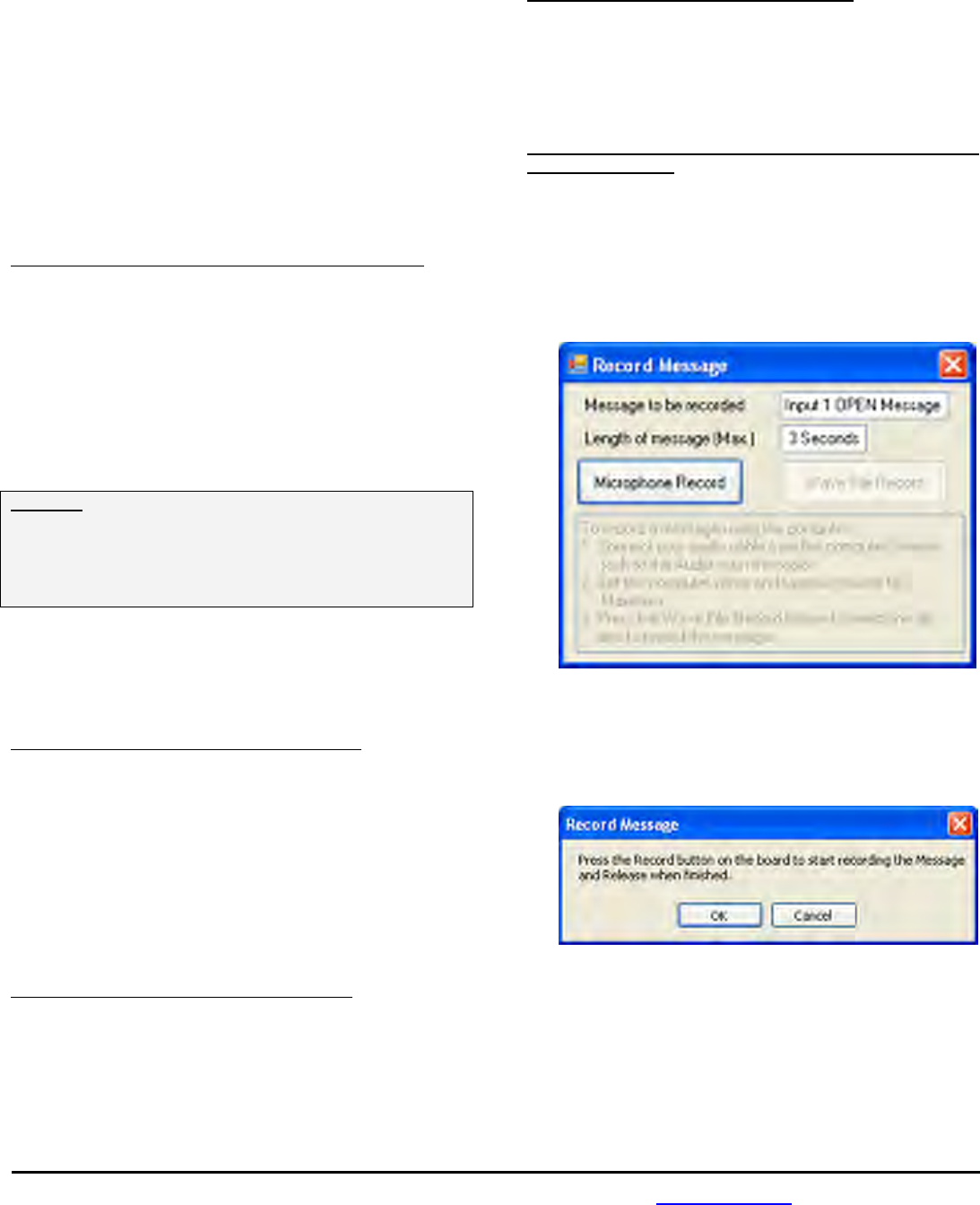
To record your Quick TalkTM Voice Messages using the on-
board microphone:
1. Read the existing radio programming.
2. Enter the Number of Inputs you will be using and program
the RQT for this change.
3. Select the Input, or Power Option, for the message you
will be recording.
4. Press the RECORD button for the message to be
recorded. The Record Message dialog box will appear.
5. Select Microphone Record.
6. The following dialog box will appear. Record the message
per the instructions, then press OK to exit record mode.
Message recording will automatically terminate after the
allotted Length of Message time if the record button has
not been released.
7. The RECORDED textbox will now indicate that the
message is recorded.
8. After you have recorded a message you can review it by
pressing the associated PLAY button. The Quick TalkTM
will transmit the message on the transmit frequency
associated with the input selected.
For assistance, call RITRON at 800-872-1872, or go to www.ritron.com 12
RECORDING YOUR QUICK TALKTM VOICE MESSAGES ...................................................................................................................
Custom Voice Messages
Recording customized Quick TalkTM voice messages gives them unmistakable meaning and significance. The standard factory
prerecorded messages of “Switch Open” and “Switch Closed” require the listener to know how the switch works and what it does.
However, when a user hears a custom message such as ‘Water pump three running hot”, the meaning is clear.
If the factory recorded messages “Switch Open” and “Switch Closed” suit your application, recording custom messages is not
necessary.
To record a custom message, follow the instructions in the Recording Your Quick TalkTM Voice Messages section of this manual. Once
recorded, play back the message to be sure you are satisfied with the quality and content of the message.
TEST YOUR QUICK TALKTM PROGRAMMING..................................................................................................................................
Once your Quick TalkTM has been programmed, it will transmit on the same frequency as your radio receivers, and will transmit any
coded squelch signals required for your radio system. Before installing the Quick TalkTM you should test for communication with your
radio receivers to verify your Quick TalkTM programming.
To test the Quick TalkTM radio transmitter:
1 Attach the Quick TalkTM flexible antenna.
2. Turn on your radio receiver.
3. Place a screwdriver, paper clip or other electrically
conductive item across the Input #1 pins.
4. Quick TalkTM will transmit the Input 1 CLOSED message,
which you should be able to hear on your radio receiver.
5. Remove the short across the Input #1 pins.
6. Quick TalkTM will transmit the Input 1 OPEN message,
which you should be able to hear on your radio receiver.
7. Repeat Steps 3 through 6 for Inputs 2, 3 and 4 if they
have been programmed to be used.
8. If you do not hear the messages, you have probably not
properly programmed the Quick TalkTM transmitter
frequency or the Quiet Call® Coded Squelch. In this case,
repeat the programming and perform this test again.
Depending upon your programming, the following sequence describes what you should hear with your radio receiver:
1. The Quick TalkTM transmitter will broadcast on the Transmit Frequency and QC or DQC Code programmed for the input that has
been activated.
2. The Quick TalkTM will broadcast silence during the programmed Message Delay on TX Time.
3. The Quick TalkTM will broadcast DTMF or Selcall ANI if it has been programmed.
4. The Quick TalkTM will broadcast the TX Alert Tone if it has been enabled.
5. The Quick TalkTM will broadcast the Location Message if it has been recorded and enabled.
6. The Quick TalkTM will broadcast the recorded Input OPEN Message if the input has gone high or the Input CLOSED Message if the
input has gone low.
7. The Input Message will be played for the number of times programmed for Play Message on each Transmission.
8. The Quick TalkTM transmitter will turn OFF and the RQT will wait for the period of time programmed for Time between
Transmissions.
9. If Number of Message Transmissions has been programmed for more than one transmission, the Quick TalkTM transmitter will
again be activated and Steps 1 – 8 will be repeated for the programmed number of transmissions.
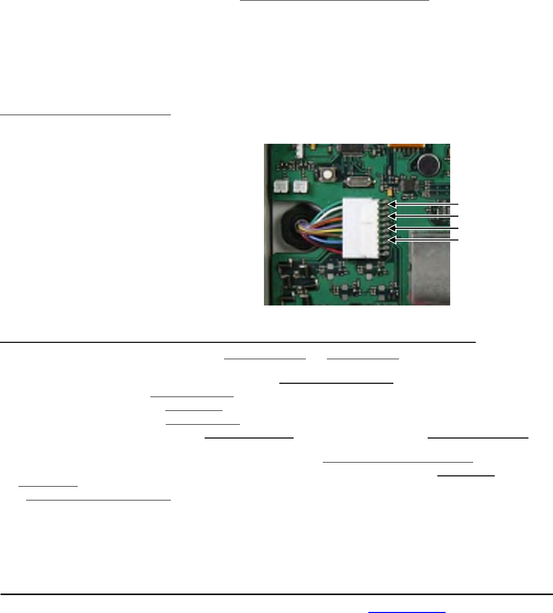
Input #1 (pins 9 &10)
Input #2 (pins 7 & 8)
Input #3 (pins 5 & 6)
Input #4 (pins 3 & 4)
For assistance, call RITRON at 800-872-1872, or go to www.ritron.com 13
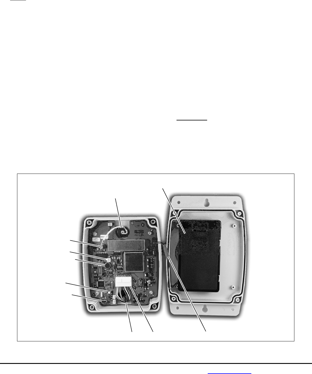
1
2
3
4
5
6
9 10 11
7
IDENTIFICATION OF QUICK TALKTM CONTROLS AND CONNECTIONS ...............................................................................................
1 Battery Holder
The battery holder accommodates the six (6) standard
“AA” alkaline cells required to power the Quick TalkTM.
NOTE: Always install a fresh set of alkaline batteries
before programming the unit.
2 BNC Antenna Connector
The antenna radiates radio signals. Before using Quick
TalkTM, make sure the antenna is fastened securely to this
connector on the front of the radio.
3 SMB Antenna Connector
This connects the front-panel, BNC antenna connector to
the radio’s printed circuit board.
4 External Audio Input
Allows input to the Quick TalkTM voice recorder from an
external audio source, such as the Line Out audio from
your computer.
5 Microphone
Microphone for recording voice messages.
6 USB Programming Connector
Connects the Quick TalkTM to the USB port on your
computer for programming.
7 Record Button
Press this button to initiate voice recording.
8 External Hookup Cable (not shown)
A 10-conductor cable for connection of external power
supply and up to four (4) switch inputs.
9 Watertight Strain Relief Cable Fitting
The External Hookup cable to your external switches
passes through this fitting. When the strain relief fitting is
used with recommended cable sizes, it provides a water-
resistant enclosure. Do not overtighten this fitting.
NOTES: Use Alpha Wire 1219C/10, 10-conductor #24
AWG cable with an outside diameter of 0.25” for a
watertight fit.
If you cannot find suitable wire, call Ritron at 800-872-
1872.
10 External Hookup Connector
A 10-position connector for the external hookup cable.
11 Battery Connector
In-line connector between the printed circuit board and the
battery holder.
IMPORTANT: Do not remove any other fasteners or
further disassemble the Quick TalkTM unit; doing so risks
damage to the unit and could void the manufacturer’s
warranty.
FIG-6: Controls & Connections
For assistance, call RITRON at 800-872-1872, or go to www.ritron.com 14
INSTALLING THE QUICK TALKTM ...................................................................................................................................................
Prior to installing the Quick TalkTM transmitter, it is important to verify all radio programming to be certain that you have achieved the
operation you desire. Re-programming requires the removal of the Quick TalkTM from it’s installed location, which can be time
consuming and frustrating.
1. Install 6 new AA Alkaline batteries into the
internal battery holder and screw the case halves
together. Be sure the case halves are pulled tightly
together for a good weather seal.
2. Select a location that provides the best possible
radio coverage.
• Avoid mounting to metal structures
• Install as high as possible
• Be sure the antenna is in a vertical position
• Be aware that metal or wires near the antenna
can block or absorb radio transmissions.
3. Temporarily mount the Quick TalkTM using the
top keyhole slot.
4. Test the radio from this location to be sure you
get the necessary radio coverage. This is
achieved by activating the transmitter with a change
on one of the inputs while a second radio-equipped
person receives the transmission at the furthest point
you will need to cover.
5. Permanently mount the Quick TalkTM using either
the four (4) corner mounts, or the top and bottom
keyhole slots.
6. Connect the antenna to the
front panel BNC connector.
If the Quick TalkTM is installed
in an outdoor location, the
antenna connection must be
sealed with weather-proof
tape to prevent corrosion and
leakage. Seal the antenna
connection to hold the
antenna in a vertical position,
to protect antenna fittings, and
to maintain water-resistance
of the Quick TalkTM in wet or
outdoor environments. Use
Archer Connector Sealant,
Radio Shack Catalog Number
278-1645 or an equivalent.
Wrap the connection with the
sealant tape and press it
securely in place. See sealant
instructions for the specific
details.
7. Connect the 4 Inputs and External +12 VDC power
provided by a 10-conductor, color -coded cable from the
front of the Quick TalkTM. This cable has been pre-
installed with a sealed strain relief to provide weather
resistance.
8. Connect your switches or sensors to the desired
Quick TalkTM inputs using wire nuts to the color-coded
cable described in Table 8. Be sure to use an appropriate
sized, sealing wire nut. The color-coded wires are 24
AWG stranded.
Table 8: RQT Color-Coded Inputs
Input 1 + GREEN
- WHITE (Ground)
Input 2 + GRAY
- ORANGE (Ground)
Input 3 + PURPLE
- YELLOW (Ground)
Input 4 + BROWN
- BLUE (Ground)
External +12 VDC
+ RED
- BLACK
9. Test each one of the input switches or sensors for the
desired operation.
To test your input switches:
a. Set your two-way radio to the channel programmed to
receive the Quick TalkTM messages.
b. Activate each switch one at a time, and listen to your
two-way radio as each message is transmitted. Write
down a description of how the condition of your switch
corresponds to the transmitted message. Then de-
activate the switch and listen to the other transmitted
message; again, write down the results.
c. By performing Step b, you should understand how
your switch works, and the meaning of it’s open and
closed states — essential knowledge if you intend to
record a descriptive voice message for each switch
condition.
Example: if your switch is a magnetic reed switch on
a door, and the switch closes when the door is
opened, you can record the phrase “Door three open”
for the switch closed condition, and then “Door three
closed” for the switch open condition. Note that
magnetic reed switches are available which work in
the opposite way.

For assistance, call RITRON at 800-872-1872, or go to www.ritron.com 15
OPTIONAL INSTALLATION INSTRUCTIONS ......................................................................................................................................
Connecting an External +12 VDC Power Supply
The Quick TalkTM may be used with an external +12 VDC power
supply. With an external supply connected the internal batteries are
automatically configured as a back-up power source. With the Quick
TalkTM programmed for External Power and batteries installed as a
back-up, it will broadcast the Power Fail message any time the
external supply is removed and will repeat the Power Fail message
once every hour (default) until external power is restored.
To use the Quick TalkTM with an external +I2 VDC power supply:
1. Use the PC Programmer to set the Quick TalkTM for External
Power Fail alarm enabled.
2. If the factory recorded “Quick Talk Power Fail” message is not
adequate, record a new Power Fail message.
3. Use Ritron #RPS-203 Power Supply (12-15 VDC, 200 mA), or
equivalent, to power the Quick TalkTM. The Quick TalkTM requires
11-15 VDC, 200 mA minimum.
4. Connect the positive (+) terminal of the power supply cable to the
RED wire on the Quick TalkTM color-coded cable.
5. Connect the negative (-) terminal of the power supply cable to the
BLACK wire on the Quick TalkTM color-coded cable.
6. Be sure to use an appropriate sized, sealing wire nut to connect
the wires. The color-coded wires are 24 AWG stranded.
Solar Panels for Operating & Charging Rechargeable Batteries
Quick TalkTM uses little power when it is not transmitting. The
estimated time the unit transmits can help determine the solar panel
size required to charge rechargeable batteries. The following formula
can be used to determine the size the solar panel:
The formula to calculate the solar panel’s required mAH:
(TX time per hour) x (TX current in mA) x (Number of hours per
day) = Req’d. mAH per day
Example: Assume the Quick TalkTM transmits for one minute of
every hour, on average (1/60 hour). Further assume the Quick TalkTM
draws 150 mA of current while transmitting.
NOTE: 150 mA is a bit higher than real consumption; the panel will
be slightly oversized.
Plug the Example into the Formula:
(1/60 hour) x (l50mA) x (24 hours/day) = 60 mAH per day
RESULTS: In this Example, the Quick TalkTM solar panel requires 60
mAH in a 24-hour period.
NOTE: Study solar panel manufacturers’ information. Quick
TalkTM input voltage cannot exceed 15 VDC.
Monitor 4-20 mA Sensor Current Loop with Quick
Talk TM Analog Input
Quick TalkTM can act as a current sink when a resistor
is connected between an Input’s positive and negative
connection. The resistance value is selected to scale
the current to the permitted 0 - 5 Volt range for the Input
to Quick TalkTM. The following formula is used to
calculate the Analog Threshold Setpoints necessary for
your application.
Analog Threshold Setpoint = 4-20 ma current (Amps)
times the resistor value (Ohms)
NOTE: A resistor value of 250Ω provides the
maximum resolution, and is the recommended value.
Using a lower resistance value with the 4-20 mA current
loop produces less than 5 V at the Input and the
measurement resolution is reduced. Using a higher
resistance value at 20 mA can produce a voltage
greater than 5V at the Input, which will not be
recognized.
To configure an Input for 4-20 mA current loop:
1. Connect a resistor between the two wires on the
Quick TalkTM color-coded cable that are associated
with the desired Input (see Table 8).
2. Connect the output of the 4-20 mA current loop
device to the positive (+) wire of the Input
connection.
3. Program the desired Input for Analog Input
operation and for the calculated Analog Setpoints.
4. Record an Input OPEN and Input CLOSED
message for the associated Input.

For assistance, call RITRON at 800-872-1872, or go to www.ritron.com 16
RITRON, INC. LIMITED WARRANTY................................................................................................................................................
WHAT THIS WARRANTY COVERS:
RITRON, INC. ("RITRON") provides the following warranty against defects in materials and/or workmanship in RITRON Radios and
Accessories under normal use and service during the applicable warranty period (as stated below). "Accessories" means antennas,
holsters, chargers, earphones, speaker/microphones and items contained in the programming and programming/service kits.
WHAT IS COVERED FOR HOW LONG WHAT RITRON WILL DO
Ritron RQT Quick TalkTM 1 year* During the first year after date of purchase, RITRON will repair or replace the
defective product, at RITRON's option, parts and labor included at no charge.
Accessories 90 days* *After date of purchase
WHAT THIS WARRANTY DOES NOT COVER:
• Any technical information provided with the covered product or any other RITRON products;
• Installation, maintenance or service of the product, unless this is covered by a separate written agreement with RITRON;
• Any products not furnished by RITRON which are attached or used with the covered product, or defects or damage from the use of
the covered product with equipment that is not covered (such as defects or damage from the charging or use of batteries other than
with covered product);
• Defects or damage, including broken antennas, resulting from:
- misuse, abuse, improper maintenance, alteration, modification, neglect, accident or act of God,
- the use of covered products other than in normal and customary manner or,
- improper testing or installation;
• Defects or damages from unauthorized disassembly, repair or modification, or where unauthorized disassembly, repair or
modification prevents inspection and testing necessary to validate warranty claims;
• Defects or damages in which the serial number has been removed, altered or defaced.
• Batteries if any of the seals are not intact.
IMPORTANT: This warranty sets forth the full extent of RITRON’s express responsibilities regarding the covered products, and is given
in lieu of all other express warranties. What RITRON has agreed to do above is your sole and exclusive remedy. No person is
authorized to make any other warranty to you on behalf of RITRON. Warranties implied by state law, such as implied warranties of
merchantability and fitness for a particular purpose, are limited to the duration of this limited warranty as it applies to the covered
product. Incidental and consequential damages are not recoverable under this warranty (this includes loss of use or time,
inconvenience, business interruption, commercial loss, lost profits or savings). Some states do not allow the exclusion or limitation of
incidental or consequential damages, or limitation on how long an implied warranty lasts, so the above limitations or exclusions may not
apply to you. Because each covered product system is unique, RITRON disclaims liability for range, coverage, or operation of the
system as a whole under this warranty.
WHO IS COVERED BY THIS WARRANTY: This warranty is given only to the purchaser or lessee of covered products when acquired
for use, not resale. This warranty is not assignable or transferable.
HOW TO GET WARRANTY SERVICE: To receive warranty service, you must deliver or send the defective product, delivery costs and
insurance prepaid, within the applicable warranty period, to RITRON, INC., 505 West Carmel Drive, Carmel, Indiana 46032,
Attention: Warranty Department. Please point out the nature of the defect in as much detail as you can. You must retain your sales
or lease receipt (or other written evidence of the date of purchase) and deliver it along with the product. If RITRON chooses to repair or
replace a defective product, RITRON may replace the product or any part or component with reconditioned product, parts or
components. Replacements are covered for the balance of the original applicable warranty period. All replaced covered products,
parts or components become RITRON’s property.
RIGHTS TO SOFTWARE RETAINED : Title and all rights or licenses to patents, copyrights, trademarks and trade secrets in any
RITRON software contained in covered products are and shall remain in RITRON. RITRON nevertheless grants you a limited non-
exclusive, transferable right to use the RITRON software only in conjunction with covered products. No other license or right to the
RITRON software is granted or permitted.
YOUR RIGHTS UNDER STATE LAW: This warranty gives you specific legal rights, and you may also have other rights which vary
from state to state.
WHERE THIS WARRANTY IS VALID: THIS WARRANTY IS VALID ONLY WITHIN THE UNITED STATES, THE DISTRICT OF
COLUMBIA AND PUERTO RICO.
Quick Assist ®
W
IRELESS
C
ALLBOX
T
RANSMITTER
O
WNER
’
S
M
ANUAL
________________________________________________________________________________________________________________________
Description Page
About the Quick Assist® Wireless Callbox Transmitter
What this Manual Covers....................................................1
General Information ............................................................1
Quick Assist® Models and Frequencies ..............................1
Quick Assist® Features .......................................................1
Important Safety Information ....................................................1
Please Note the Following with Regard to RF Exposure
for this Product .........................................................................2
Frequently Asked Questions about Quick Assist®
Programming............................................................................3
Quick Assist® Programming Features ......................................4
Summary Screen ................................................................4
Append Battery Messages.............................................4
Low Battery Alarm Enabled ...........................................4
Play Location Message..................................................4
Message Delay on TX ...................................................4
Description.....................................................................4
Input Screen........................................................................4
Frequency Table............................................................4
Transmit Frequency.......................................................4
QC or DQC Code...........................................................5
DQC Invert.....................................................................5
Compand .......................................................................5
TX Alert Tone ................................................................5
Press and Hold Reset....................................................5
ANI.................................................................................5
Message Repeat............................................................5
Voice Messages ............................................................5
Power Options Screen ........................................................6
Frequency Table............................................................6
Transmit Frequency.......................................................6
QC or DQC Code...........................................................6
DQC Invert.....................................................................6
Compand .......................................................................6
TX Alert Tone ................................................................6
Description Page
ANI ................................................................................ 6
Message Repeat ........................................................... 6
Quick Assist® Default Programming......................................... 6
Programming Your Quick Assist® Transmitter Frequency and
Tone......................................................................................... 7
Table 1: MURS model radios only ...................................... 7
Table 2: VHF Business band models................................. 7
Table 3: UHF Business band models ................................ 7
Table 4: Canadian UHF model radios only ......................... 8
Table 5: Quiet Call Tone Codes.......................................... 8
Table 6: Digital Quiet Call Codes....................................... 8
Recording Your Quick Assist® Voice Messages....................... 9
Assist Message................................................................... 9
Reset Message................................................................... 9
Low Battery Message ......................................................... 9
Location Message............................................................... 9
Record Custom Voice Messages............................................. 9
To Record Your Quick Assist® Voice Messages
using the on-board microphone: ......................................... 9
Test Your Quick Assist® Programming................................... 10
Installation / Replacement of Batteries................................... 10
Automatic Low Battery Alert Message ................................... 11
Installing the Quick Assist®.................................................... 11
Care and Maintenance........................................................... 11
Identification of Quick Assist® Controls and Connectors ........ 12
FIG-1: Controls & Connectors.......................................... 12
Ritron, Inc. Limited Warranty.................................................. 13
___________________________________________________________________________________________________________
Ritron Publication 14500079 Rev. B 10-11
© 2011 Ritron, Inc. All rights reserved. Ritron, Patriot, Jobcom, OutPost, GateGuard, Quiet Call and Quick Assist® are registered trademarks of Ritron,
Inc. Quick Talk, Liberty and RadioNexus are trademarks of Ritron, Inc.
Call 800-USA-1-USA for the right Wireless Solutions to your communication needs.
P.O. Box 1998 • Carmel, Indiana 46082-1998 • USA
Phone: 317-846-1201; 800-USA-1-USA (800-872-1872) • Fax: 317-846-4978
Email: ritron@ritron.com • Website: www.ritron.com

________________________________________________________________________________________________
For assistance, call RITRON at 800-872-1872, or go to www.ritron.com 1
ABOUT THE QUICK ASSIST® WIRELESS CALLBOX TRANSMITTER...................................................................................................
What this Manual Covers
This manual covers basic operation of the Quick Assist®
Wireless Callbox Transmitter. For most applications, this is
all the information you will need.
General Information
The Quick Assist® is a RITRON Wireless Callbox
Transmitter, specialized for indoor retail or commercial use,
and pre-programmed to transmit a custom recorded
“Assistance Needed” message when the Message push-
button is pressed for customer assistance. Personnel know
from these message transmissions in which specific areas a
customer needs assistance.
The Quick Assist® is easily programmed to transmit on
either an existing or a new radio frequency, with the most
popular sub-audible coded squelch formats, such as Quiet
Call® or Digital Quiet CaII®. This enables all your personnel
with JOBCOM®, PATRIOT™ or equivalent two-way radios to
hear the voice messages instantly.
The Quick Assist® can be installed in a wide variety of
indoor locations. Because it’s six internal AA Alkaline
batteries will power the unit for about a year, the Quick
Assist® does not require AC line power.
Quick Assist® Features
• Internal radio transmitter (separate VHF and UHF
models).
• User-recorded voice messages; total recording time of 24
seconds.
• Typical range of 1/4 mile.
• Internal battery holder for six (6) AA Alkaline cells.
• Typical operating battery life of 1 year.
• Automatic low battery message.
• Programmable Features:
- Transmit Frequency;
- Tone Coded Squelch Encoder (Quiet Call®)
- Digital Coded Squelch Encoder (Digital Quiet CaIITM)
- DTMF and Selcall ANI
- Message transmission schedule and limits.
• Limited One-year Factory Warranty.
Quick Assist® Models and Frequencies
There are Quick Assist® radios available for each of the three
most popular professional radio communications bands. The
model number appears on a label on the bottom of the case.
MODELS BAND FREQUENCY RANGE
RQA-151 VHF-FM 150 to 165 MHz
RQA-152
RQA-151-CANADA
RQA-152-CANADA
RQA-151M MURS 151.820, 151.880, 151.940,
RQA-152M 154.570, 154.600 MHz
RQA-451 UHF-FM 450 to 470 MHz
RQA-452
RQA-451-CANADA
RQA-452-CANADA
Ritron manufactures mobile, portable and base station two-way
radios and repeaters for use with Quick Assist®. Ritron pioneered
the use of Color Dots on radios to identify frequencies.
Factory-programmed, default Quick Assist® frequencies are:
MODELS FREQUENCY BANDWIDTH
RQA-151, RQA-152 151.625 MHz (Red Dot) narrowband
RQA-151M, RQA-152M 154.570 MHz (Blue Dot) wideband
RQA-151-CANADA 151.055 MHz wideband
RQA-152-CANADA
RQA-451, RQA-452 467.850 MHz (Silver Star) narrowband
RQA-451-CANADA 458.6625 MHz wideband
RQA-452-CANADA
See page 4 for instructions on changing the Quick Assist®
transmit frequency to match an existing radio system.
For Your FREE copy of the Basic PC Programmer
go to: www.ritron.com/basicprogrammer
Note: Before you begin using the above PC programmer, you will
also need the following:
• A USB to Mini B 5-pin cable. You can purchase this cable
from Ritron (pn #60201119) or, since this is a commonly
used cable, you may want to check to see if you already own
a compatible cable.
• Also, your PC will need:
- Windows XP or newer version and
- Your PC will need to have a USB port.
IMPORTANT SAFETY INFORMATION...............................................................................................................................................
NOTICE: The Quick Assist® unit should not be used to report conditions relating to safety of life or property.
To reduce the risk of fire, electric shock or personal injury, follow these basic safety instructions when using this unit.
1. Read and follow all instructions.
2. Disconnect the unit before cleaning. Do not use liquid or aerosol cleaners.
3. Use only approved power sources for the unit.
4. During thunderstorms, avoid contact with this unit and any external antenna system or wiring.
5. If you are unsure whether your installation will be safe, contact an experienced electrician or electronics technician.

________________________________________________________________________________________________
For assistance, call RITRON at 800-872-1872, or go to www.ritron.com 2
PLEASE NOTE THE FOLLOWING WITH REGARD TO RF EXPOSURE FOR THIS PRODUCT....................................................................
EXPOSURE TO RADIO FREQUENCY ENERGY:
RQA-151, RQA-151M, RQA-451, RQA-451-CANADA,
RQA-152, RQA-152M, RQA-452, RQA-452-CANADA
This product generates radio frequency (RF) energy when the
button on the front of the unit is depressed. This product has
been evaluated for compliance with the maximum permissible
exposure limits for RF energy at the maximum power rating of
the unit when using antennas available from RITRON.
For both the AFB-1545 and the standard internal antennas, at
the 20 cm (7.9 inches) minimum expected separation distance
and greater, the maximum RF exposure is well below the
General Population/Uncontrolled limits. Antennas other than
those available from RITRON have not been tested for
compliance and may or may not meet the exposure limits at
the distances given. Higher gain antennas are capable of
generating higher fields in the strongest part of their field and
would, therefore, require a greater separation from the
antenna. This product is not to be used by the general public
in an uncontrolled environment unless compliance with the
Uncontrolled/General Population limits for RF exposure can be
assured.
To limit exposure to RF energy to levels below the limit, please
observe the following:
• Use only the antenna(s) available from RITRON for these
models. DO NOT operate the radio without an antenna.
• DO NOT activate the transmitter when not actually wishing
to transmit. These radios transmit recorded messages of a
pre-determined length to prevent continuous transmit times.
• When transmitting, make certain that the distance limits for
the particular model in use are observed.
• DO NOT allow children to operate the radio.
When used as directed, this series of radios is designed to
comply with the FCC’s RF exposure limits for
“Uncontrolled/General Population”. In addition, they are
designed to comply with the following Standards and
Guidelines:
• United States Federal Communications Commission, Code
of Federal Regulations; 47 CFR §§ 2 sub-part J.
• American National Standards Institute (ANSI) / Institute of
Electrical and Electronic Engineers (IEEE) C95. 1-1992.
• Institute of Electrical and Electronic Engineers (IEEE)
C95.1-1999 Edition.
Copyright Telecommunications Industry Association
LISEZ S'IL VOUS PLAÎT LA DÉCLARATION SUIVANTE DE L'EXPOSITION RF POUR CE PRODUIT. ..........................................................
Exposition à l'énergie radioélectrique:
RQA-151, RQA-151M, RQA-451, RQA-451-CANADA,
RQA-152, RQA-152M, RQA-452, RQA-452-CANADA
Ce produit génère énergie radiofréquence (RF) lorsque le
bouton sur le front de l'unité est enfoncé. Ce produit a été
évalué pour le respect des limites de l'exposition maximale
admissible pour l'énergie RF à la cote de puissance maximale
de l'émetteur lorsque vous utilisez des antennes RITRON.
Lorsque vous utilisez l'AFB-1545 ou les antennes internes
standards, à la 20 cm (7,9 pouces) minimum prévu à distance
de séparation et au-delà, l'exposition RF maximale est
inférieure à la Population générale / Uncontrolled limite.
Antennes non-RITRON n'ont pas été testés pour la conformité
et peuvent ou peuvent ne pas satisfaire les limites d'exposition
à des distances donnés. Antennes de gains plus élevés sont
capables de générer des champs plus élevés dans la partie
plus forte de leur domaine et nécessiteraient donc une plus
grande séparation de l'antenne. Ce produit ne doit ne pas être
utilisé par le public en général dans un environnement non
contrôlé, à moins que la conformité avec la Uncontrolled / les
limites de l'ensemble de la Population pour l'exposition RF
peuvent être assurés.
Pour limiter l'exposition à l'énergie RF à des concentrations
inférieures à la limite, veuillez observer ce qui suit :
• Utilisez uniquement des antennes RITRON pour ces
modèles. NE fonctionnent pas sans une antenne de la
radio.
• N'utilisez pas l'émetteur lorsque vous ne souhaitez pas
transmettre. Ces radios transmettent enregistré des
messages d'une durée prédéterminée pour empêcher
continu transmettent times.
• Lors de la transmission, s'assurer que les limites de
distance pour le modèle particulier en usage sont
observées.
• NE laissez pas les enfants pour l'exploitation de la radio.
Lorsqu'il est utilisé conformément aux directives, cette série de
radios est conçue pour respecter les limites d'exposition RF
pour « Incontrôlée / Population générale ». En outre, ils sont
conçus pour respecter les normes et lignes directrices
suivantes :
• United States Federal Communications Commission, Code
of Federal Regulations; 47 CFR §§ 2 sub-part J.
• American National Standards Institute (ANSI) / Institute of
Electrical and Electronic Engineers (IEEE) C95. 1-1992.
• Institute of Electrical and Electronic Engineers (IEEE)
C95.1-1999 Edition.
Copyright Telecommunications Industry Association

________________________________________________________________________________________________
For assistance, call RITRON at 800-872-1872, or go to www.ritron.com 3
FREQUENTLY ASKED QUESTIONS ABOUT QUICK ASSIST® PROGRAMMING.....................................................................................
Do I have to program my Quick Assist®?
You may not need to program your Quick Assist® at all. If you
purchased a Quick Assist® unit that is factory programmed to
your radio system frequency (check the frequency on your
radios and the Quick Assist®), and you do not use a form of
Quiet Call coded squelch, you can install the batteries and start
using Quick Assist®. The factory default voice message is
“Assistance Needed”. Otherwise, read this manual before
programming your Quick Assist®.
Do I need to program every feature?
In many cases, no. The factory pre-programmed settings,
explained in the instructions, may meet many of your needs.
How do I program my Quick Assist®?
All programming is accomplished with the RITRON RQA/RQT
PC Programmer software available at www.ritron.com.
The programmer software requires Window® XP or greater,
and a PC computer with a USB port.
What if I don’t find what I need in this manual?
Call Ritron (317-846-1201): we will be glad to help you. For
most applications, this manual should cover everything you will
need to know. However, the Quick Assist® has more
capabilities and features than described here.
Will it harm the Quick Assist® if I program it improperly?
No; however, you may need to erase all programming and start
over. Feel free to experiment with the various features and
possible configurations.
Can my settings or messages get lost or erased if the
battery runs down, or if my Quick Assist® is
disconnected?
No. The settings and voice messages you enter are stored in
special electronic memory devices in the Quick Assist® that do
not require power to hold the information. This means that if
the batteries run down or if you remove them, you will not need
to reprogram the Quick Assist®. All your settings and
messages will be there for you when you install fresh batteries.
What if I need more range?
To increase the range of your Quick Assist® transmissions, we
suggest you first relocate the unit. Ritron also manufactures
radio repeaters to increase the range not only for your Quick
Assist®, but also for your entire radio system.
What is my Radio System Frequency?
Ritron pioneered the Color Dot system to simplify the
identification of radio system frequencies for Ritron Jobcom®
radios. Color Dots are placed on the bottoms of and inside the
enclosures of all Jobcom® radios. Other manufacturers have
also adopted this idea.
To identify your assigned frequency if your radios do not have
a color dot, locate a label identifying the receiver frequency in
megahertz (MHz). Your assigned frequency is also shown on
your F.C.C. Station License. Consult your radio user manual,
your dealer, or call Ritron for help if you cannot determine your
radio’s receiver frequency.
Do I need to program my Quick Assist® transmitter
frequency?
The original factory-programmed transmitter frequency of your
Quick Assist® is marked on the outside of the shipping box. If
the Quick Assist® frequency matches your radio system
frequency, and if the Quick Assist® has not been
reprogrammed since it left the factory, you will not have to
program the transmitter frequency.
What is Quiet Call® Sub Audible Coded Squelch?
The Quick Assist® radio transmitter is compatible with two
standard communications industry sub audible signaling
formats: QC (Quiet Call® Interference Eliminator), and DQC
(Digital Quiet Call® Interference Eliminator). Both Quiet Call®
formats unlock receivers programmed to require these codes,
they screen out interference from other radio systems
operating on your same frequency.
QC Quiet Call® is Ritron’s trade name for what the
communications industry calls sub-audible (below the range of
human hearing) tone squelch, or CTCSS (Continuous Tone
Coded Subaudible Squelch) or Interference Eliminator. Other
radio manufacturers use different trade-names for essentially
the same system. You may program a specific QC code into
your Quick Assist® to transmit with the voice messages, which
will “unlock” the receivers in your radio system.
DQC Digital Quiet Call® is Ritron’s digital coded squelch, and
works the same as QC, except it is a digital code that is
transmitted with the voice messages.
Do I need to program my Quick Assist® with a Quiet Call
Code?
Your radio system may or may not use coded squelch
signaling. If you have programmed the Quick Assist® to match
your radio frequency, and your radios are not receiving Quick
Assist® transmissions unless the “monitor” or “test” button is
pressed on your radio, your system is probably using Coded
Squelch. Refer to your radio manual, or contact your radio
dealer or Ritron if you are unsure about this issue.
If your Quick Assist® was previously programmed with a Quiet
Call® code and you need to remove it, follow the programming
instructions, using No Tone code, “44”, as shown in the table.
What is Digital Quiet Call®?
Digital Quiet Call® (DQC) is a digital sub-audible coded
squelch system.
Do I need to program my Quick Assist® with a Digital Quiet
Call code?
If your radio system does not use Digital Quiet Call®, or any
other trade name equivalent, you will not need to program a
Digital Quiet Call® code.
What is the purpose of testing the Quick Assist® radio
transmitter?
After programming your radio, your Quick Assist® will transmit
on the same frequency as your radio receivers, using any
coded squelch signals required for your radio system.
Do I need to test my Quick Assist® Transmitter?
Yes; performing this test now will save you time and confusion
later.
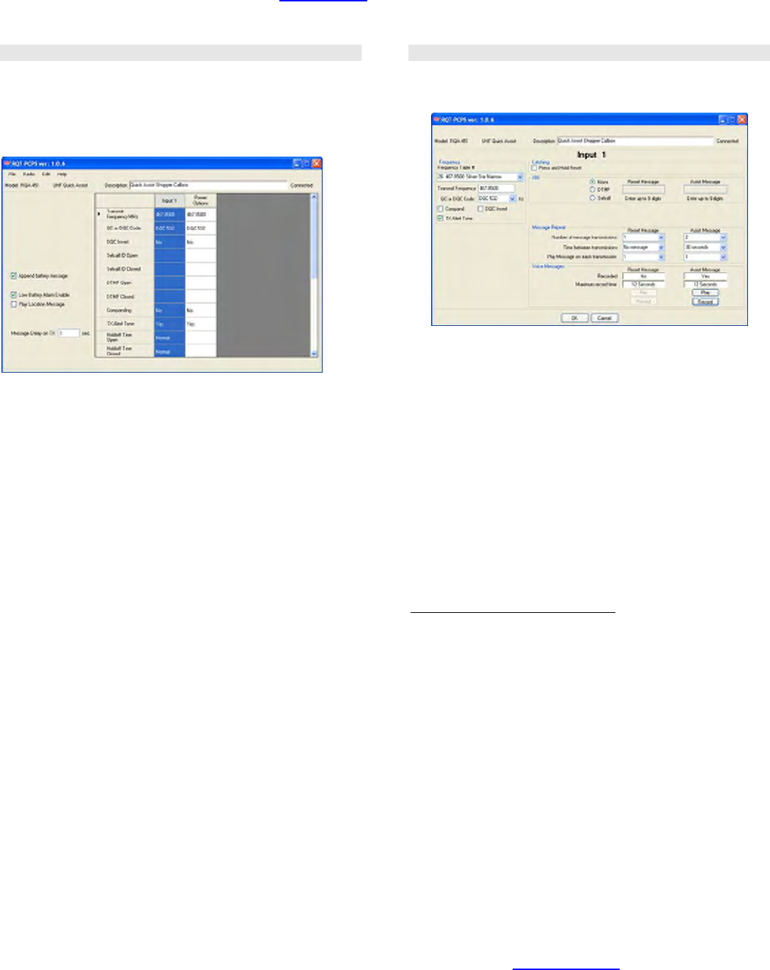
________________________________________________________________________________________________
For assistance, call RITRON at 800-872-1872, or go to www.ritron.com 4
QUICK ASSIST® PROGRAMMABLE FEATURES ...............................................................................................................................
The Quick Assist® can be programmed with unique voice messages and attributes. All programming is accomplished with the RITRON
RQA/RQT PC Programmer software available at www.ritron.com.
The programmer software requires Window® XP or greater, and a PC computer with a USB port.
Summary Screen
After reading the radio programming, a summary screen will
appear with a tabulated display of the input programming.
Double-click on the input column to program the Quick Assist®
attributes. Radio-wide features are programmed from the
Summary Screen.
FIG-1: Programmer Summary Screen
Append Battery Messages
If selected, the Low Battery message will play at the conclusion
of any “Assistance needed” or “Quick Assist call cleared”
message, as well as on the low battery event.
Low Battery Alarm Enable
If selected, a Low Battery message is transmitted when the
internal batteries are in need of replacement.
Play Location Message
If selected, the Quick Assist® will transmit a recorded Location
message immediately prior to any “Assistance needed”, “Quick
Assist call cleared”, or Low Battery message.
Message Delay on TX
This sets a time delay between turning on the Quick Assist®
transmitter and playing any messages, or ANI strings.
Description
Enter a brief description (35 characters or less) of the Quick
Assist® use, location, customer, etc. This can be useful when
reading out the Quick Assist® programming at a later date, or
when saving a programming profile for use with other radios.
Input Screen
The Input Screen is used to uniquely program the behavior of
the Quick Assist® when the front panel push button is pressed.
FIG-2: Programmer Input Screen
Frequency Table
To match other RITRON radios, the owner can select from a
table of transmit frequencies. Simply “read-out” the Frequency
Code of your RITRON portable, mobile or base radio and enter
the same code when programming the Quick Assist®. Note
that all RQA-151 and RQA-451 table frequencies operate in
narrow band mode (12.5 kHz).
Transmit Frequency
Once you have selected a code from the Frequency Table the
actual transmit frequency will appear here. If your operating
frequency does not appear on the Frequency Table list, a
licensed radio service technician will be able to enter other
frequencies within the radio’s operating band.
To identify your assigned frequency:
• Read-out the Frequency Code of the RITRON radio you
intend to use with the Quick Assist®.
• Check for a corresponding color dot on the radio you intend
to use with the Quick Assist®.
• Locate a label identifying the receiver frequency in
megahertz (MHz).
• Your assigned frequency is shown on your FCC Station
License.
• Call your radio dealer or Ritron for help if you cannot
determine your radio’s receiver frequency.
• The original factory-programmed transmitter frequency of
your Quick Assist® is marked on the outside of the shipping
box.
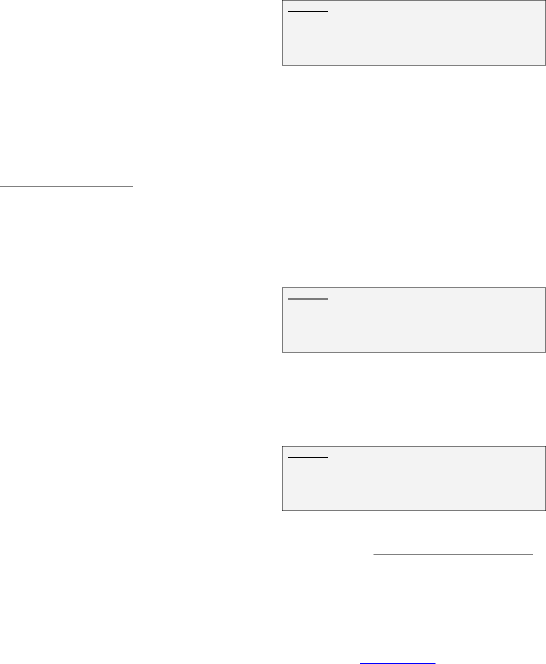
________________________________________________________________________________________________
For assistance, call RITRON at 800-872-1872, or go to www.ritron.com 5
QUICK ASSIST® PROGRAMMABLE FEATURES ...............................................................................................................................
QC or DQC Code
Select from a list of QC and DQC Codes to transmit subaudible
squelch tones for interference elimination.
The Quick Assist® radio transmitter is compatible with two
standard communications industry sub-audible signaling
formats: QC (Quiet Call® Interference Eliminator), and DQC
(Digital Quiet CallTM Interference Eliminator). Both Quiet Call
formats unlock receivers programmed to require these codes --
they screen out interference from other radio systems
operating on your transmit frequency.
QC Quiet Call® is Ritron’s trade name for what the
communications industry calls sub-audible (below the range of
human hearing) tone squelch, or CTCSS (Continuous Tone
Coded Subaudible Squelch).
DQC Digital Quiet CallTM is Ritron’s digital coded squelch, and
works the same as QC, except it is a digital code that is
transmitted with the voice messages.
To identify your QC or DQC tone:
• Read-out the Tone Code of the RITRON radio you intend to
use with the Quick Assist®.
• Refer to your radio manual.
• Contact your radio dealer or Ritron if you are unsure about
this issue.
DQC Invert
The DQC Digital Quiet CallTM code can be inverted for systems
that require inversion.
Compand
Some two-way radios have a feature referred to as
“companding”. It is a way of eliminating background hiss or
noise, making the radio sound clearer. “Companding” is a
combination of audio “compression” in the transmitter and
audio “expanding” in the receiver. The Quick Assist® can be
programmed for audio compression. To determine if your
existing 2-way radios are using the Companding feature, you
can check the radio’s User Manual, contact your radio dealer,
or call Ritron for help.
If you are unable to determine if your portable radio uses the
companding feature, we suggest the following:
1. Leave the radio in the factory default setting with no
companding.
2. Activate the transmitter of the Quick Assist® and listen to
the message from your portable radio. If the received
audio is acceptable, you should not need to set the Quick
Assist® for companding.
TX Alert Tone
By default, the Quick Assist® will transmit an alert tone before
each voice message transmission. This feature can be
disabled via the PC programmer.
Press and Hold Reset
Often it is desirable to repeat the “Assistance message”
without limitation until the call has been answered. With Press
and Hold Reset enabled the front panel push button can be
held down for 5 seconds to reset the Quick Assist® to the
standby condition.
Example: To use a Quick Assist® in a paint department, you
want it to re-transmit a message several times after a “Press
for Help” push-button is pressed. With the Quick Assist® set
for Press and Hold Reset an employee can terminate the
message transmissions, and in the process send a “Quick
Assist call cleared” message.
ANI
The “Assistance needed” and “Quick Assist call cleared”
conditions can each be programmed with a unique 1-9 digit
DTMF or 3-7 digit Selcall ANI string. The ANI will be
transmitted immediately prior to the Alert Tone and Input
message. To program an ANI string, select Selcall or DTMF
and enter the string in the value field.
Message Repeat
Number of Message Transmissions
You can set a limit to the number of times the message will be
transmitted at a scheduled interval.
Time Between Transmissions
This sets the amount of time the Quick Assist® will wait
between repeated transmissions. You can program a different
Wait Time for the “Assistance needed” condition, and for the
“Quick Assist call cleared” condition.
Example: When the “Press for Help” push-button pressed in
the paint department, an “Assistance needed in paint”
message is to be transmitted every 30 seconds for 5 minutes.
To accomplish this the Quick Assist® is programmed for 10
message transmissions with a time between transmissions
setting of 30 seconds.
The Quick Assist® is set at the factory to transmit the “Quick
Assist call cleared” message only once.
Repeat Message on each transmission
Your recorded voice message can be programmed to repeat
from one time to nine times on each Quick Assist® radio
transmission. Urgent messages may require more phrase
repeats.
Example: The Quick Assist® is to be used as an emergency
call button in a parking garage. If “Repeat on each
Transmission” is set to 3, the Quick Assist® would transmit
“Emergency in garage level 2, Emergency in garage level 2,
Emergency in garage level 2” when the front-panel pushbutton
is pressed.
Voice Messages
The Assist and Reset messages are recorded via the Input
Screen. Refer to the Recording Your Quick TalkTM Messages
section of this manual for instructions on recording voice
messages. The Recorded box indicates whether or not a
message has been recorded. The Maximum Record Time for
each message is also indicated.
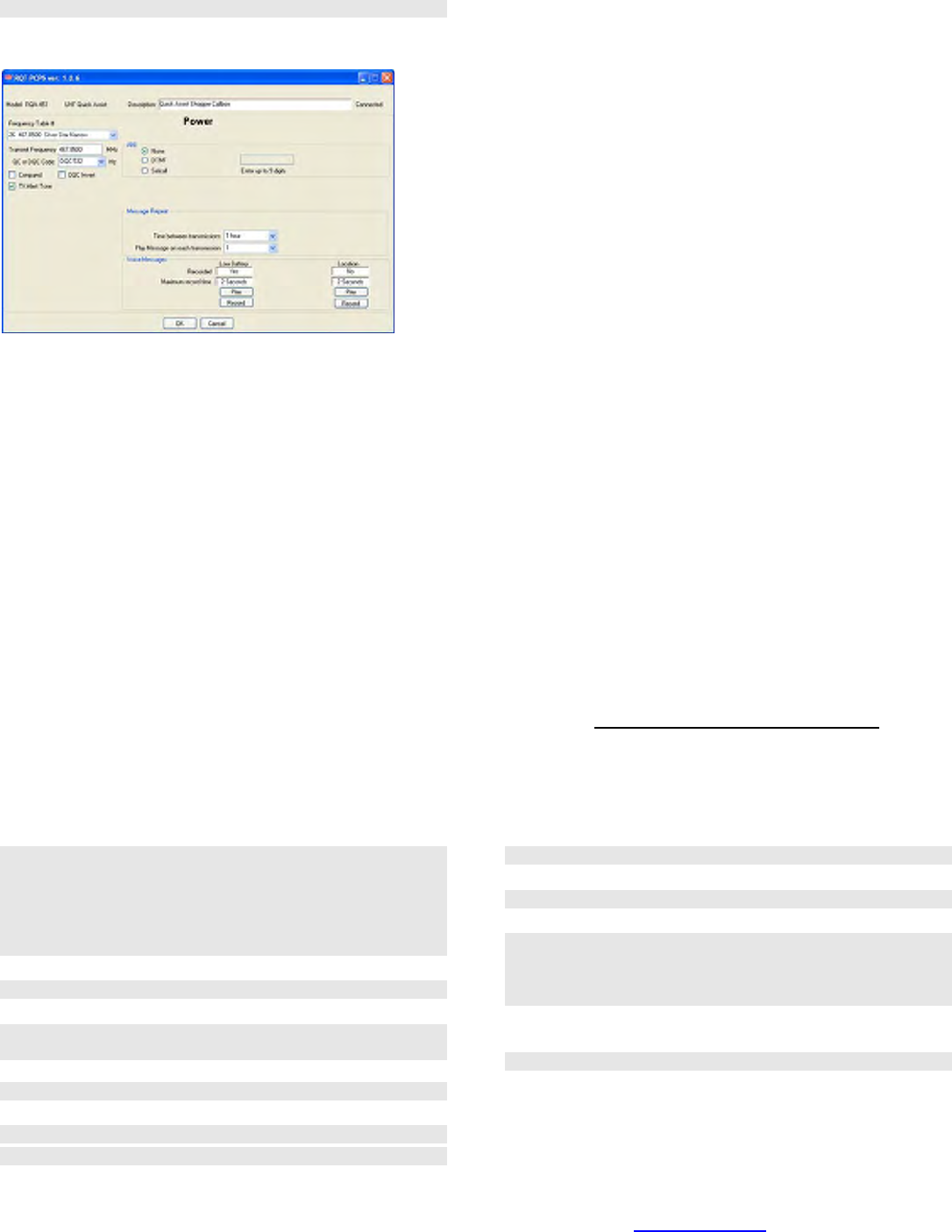
________________________________________________________________________________________________
For assistance, call RITRON at 800-872-1872, or go to www.ritron.com 6
QUICK ASSIST® PROGRAMMABLE FEATURES ...............................................................................................................................
Power Options Screen
The Low Battery Alert message can be programmed for unique
frequencies, tones, and Voice message.
FIG-5: Programmer Power Options Screen
Frequency Table #
To match other RITRON radios, the owner can select from a
table of transmit frequencies. Simply “read-out” the Frequency
Code of your RITRON portable, mobile or base radio and enter
the same code when programming the Quick Assist®.
Transmit Frequency
Once you have selected a Frequency Code the actual transmit
frequency will appear here. If your operating frequency does
not appear on the Frequency Code list, a licensed radio
service technician will be able to enter other frequencies within
the radio’s operating band.
QC or DQC Code
Select from a list of QC and DQC Codes to transmit subaudible
squelch tones for interference elimination.
DQC Invert
The DQC Digital Quiet CallTM code can be inverted for systems
that require inversion.
Compand
Set Compand for compression of the transmit audio.
“Companding” is a combination of audio “compression” in the
transmitter and audio “expanding” in the receiver. To determine
if your existing 2-way radios are using the Companding
feature, you can check the radio’s User Manual, contact your
radio dealer, or call Ritron for help.
TX Alert Tone
The Quick Assist® can transmit an alert tone before each voice
message transmission.
ANI
Power Alerts messages can be programmed with a unique 9
digit DTMF or Selcall ANI string. The ANI will be transmitted
immediately prior to the Alert Tone and Power Alert message.
To program an ANI string, select Selcall or DTMF and enter
the string in the value field.
Message Repeat
Time between transmissions
This sets the amount of time the Quick Assist® will wait before
re-transmitting a Low Battery Alert message. Keep in mind
that the Quick Assist® turns off after all scheduled “Assistance
needed” messages have been transmitted. If the Low Battery
Alert “Time between transmissions” is greater than the total
scheduled assistance time the Low Battery Alert message will
not be repeated.
Repeat Message on each transmission
Your recorded voice message can be programmed to repeat
from one time to nine times on each Quick Assist® radio
transmission, depending on how you program this feature.
Urgent messages may require more phrase repeats.
Voice Messages
Refer to the Recording Your Quick Assist® Messages section
of this manual for instructions on recording voice messages.
QUICK ASSIST® DEFAULT PROGRAMMING ....................................................................................................................................
TX Frequency
RQA-151, -152 03 151.625 MHz NB
RQA-151M, -152M 02 154.570 MHz WB
RQA-151-CANADA 01 151.055 MHz WB
RQA-451, -452 26 467.850 MHz NB
RQA-451-CANADA 01 458.6625 MHz WB
QC/DQC Code 44 No Tone
DQC Invert No
Compand No
Reset Operation Reset from Front Panel
Button
Reset Button Hold Time 5 sec.
Input Operation Normal
Latching Input Mode Yes
Number of Inputs 1
TX Alert Tone Yes
Battery Saver Yes
Low Battery Message Yes
Message Delay on TX 1 sec.
Recorded Messages
RQA Message “Assistance needed”
Reset Message “Quick Assist call cleared”
Low Battery “Quick Assist battery”
Number of Times Recorded Message
is repeated on each Transmission 1 time
Number of Times the Transmission is sent 2 times
Wait Time between Transmissions 30 sec.
________________________________________________________________________________________________
For assistance, call RITRON at 800-872-1872, or go to www.ritron.com 7
PROGRAMMING YOUR QUICK ASSIST® TRANSMITTER FREQUENCY AND TONE................................................................................
The Quick Assist® transmitter operates exclusively on a 12.5 kHz narrow band channel bandwidth. Many of the Frequency Table
Codes programmed in your compatible Ritron radios are for 25 kHz wide band channels. If these codes are selected when
programming your Quick Assist® radio, the radio will operate at a 12.5 kHz narrow band channel bandwidth. This allows you to use
your Quick Assist® with all of your existing radios.
The RQA-151M and RQA-152M MURS model radios can only be programmed to the codes listed on Table 1 below. VHF Business
band models can be programmed to the codes listed on Table 2 below, or can be programmed to any valid licensed frequency between
150-165 MHz EXCEPT the frequencies listed on MURS Table 1 below.
TABLE 1: MURS model radios only (US)
Frequency Channel
Code (MHz) Color Dot Bandwidth
01 154.600 Green Dot 25 kHz
02 154.570 Blue Dot 25 kHz
19 151.820 MURS 12.5 kHz
20 151.880 MURS 12.5 kHz
21 151.940 MURS 12.5 kHz
22 154.600 MURS 12.5 kHz
23 154.570 MURS 12.5 kHz
TABLE 2: VHF Business band models (US)
Frequency Channel
Code (MHz) Color Dot Bandwidth
03 151.625 Red Dot 12.5 kHz
04 151.955 Purple Dot 12.5 kHz
05 151.925 12.5 kHz
06 154.540 12.5 kHz
07 154.515 12.5 kHz
08 154.655 12.5 kHz
09 151.685 12.5 kHz
10 151.715 12.5 kHz
11 151.775 12.5 kHz
12 151.805 12.5 kHz
13 151.835 12.5 kHz
14 151.895 12.5 kHz
15 154.490 12.5 kHz
16 151.655 12.5 kHz
17 151.745 12.5 kHz
18 151.865 12.5 kHz
24 151.700 12.5 kHz
25 151.760 12.5 kHz
26 152.700 12.5 kHz
TABLE 3: UHF Business band models (US)
Frequency Channel
Code (MHz) Color Dot Bandwidth
01 467.7625 J 12.5 kHz
02 467.8125 K 12.5 kHz
03 464.5500 Yellow Dot 12.5 kHz
04 464.5000 Brown Dot 12.5 kHz
05 467.8500 Silver Star 12.5 kHz
06 467.8750 Gold Star 12.5 kHz
07 467.9000 Red Star 12.5 kHz
08 467.9250 Blue Star 12.5 kHz
09 469.2625 12.5 kHz
10 462.5750 White Dot 12.5 kHz
11 462.6250 Black Dot 12.5 kHz
12 462.6750 Orange Dot 12.5 kHz
13 464.3250 12.5 kHz
14 464.8250 12.5 kHz
15 469.5000 12.5 kHz
16 469.5500 12.5 kHz
17 463.2625 12.5 kHz
18 464.9125 12.5 kHz
19 464.6000 12.5 kHz
20 464.7000 12.5 kHz
TABLE 3: UHF Business band models (US) cont.
Frequency Channel
Code (MHz) Color Dot Bandwidth
21 462.7250 12.5 kHz
22 464.5000 12.5 kHz
23 464.5500 12.5 kHz
24 467.7625 12.5 kHz
25 467.8125 12.5 kHz
26 467.8500 12.5 kHz
27 467.8750 12.5 kHz
28 467.9000 12.5 kHz
29 467.9250 12.5 kHz
30 461.0375 12.5 kHz
31 461.0625 12.5 kHz
32 461.0875 12.5 kHz
33 461.1125 12.5 kHz
34 461.1375 12.5 kHz
35 461.1625 12.5 kHz
36 461.1875 12.5 kHz
37 461.2125 12.5 kHz
38 461.2375 12.5 kHz
39 461.2625 12.5 kHz
40 461.2875 12.5 kHz
41 461.3125 12.5 kHz
42 461.3375 12.5 kHz
43 461.3625 12.5 kHz
44 462.7625 12.5 kHz
45 462.7875 12.5 kHz
46 462.8125 12.5 kHz
47 462.8375 12.5 kHz
48 462.8625 12.5 kHz
49 462.8875 12.5 kHz
50 462.9125 12.5 kHz
51 464.4875 12.5 kHz
52 464.5125 12.5 kHz
53 464.5375 12.5 kHz
54 464.5625 12.5 kHz
55 466.0375 12.5 kHz
56 466.0625 12.5 kHz
57 466.0875 12.5 kHz
58 466.1125 12.5 kHz
59 466.1375 12.5 kHz
60 466.1625 12.5 kHz
61 466.1875 12.5 kHz
62 466.2125 12.5 kHz
63 466.2375 12.5 kHz
64 466.2625 12.5 kHz
65 466.2875 12.5 kHz
66 466.3125 12.5 kHz
67 466.3375 12.5 kHz
68 466.3625 12.5 kHz
69 467.7875 12.5 kHz
70 467.8375 12.5 kHz
71 467.8625 12.5 kHz
72 467.8875 12.5 kHz
73 467.9125 12.5 kHz
74 469.4875 12.5 kHz
75 469.5125 12.5 kHz
76 469.5375 12.5 kHz
77 469.5625 12.5 kHz
________________________________________________________________________________________________
For assistance, call RITRON at 800-872-1872, or go to www.ritron.com 8
PROGRAMMING YOUR QUICK ASSIST® TRANSMITTER FREQUENCY AND TONE................................................................................
TABLE 4: Canadian UHF model radios only
Code Frequency (MHz) Color Dot Channel Bandwidth
01 458.6625 25 kHz
02 469.2625 25 kHz
TABLE 5: Quiet Call Tone Codes
Code Frequency
00 None
01 67.0
02 71.9
03 74.4
04 77.0
05 79.7
06 82.5
07 85.4
08 88.5
09 91.5
10 94.8
Code Frequency
11 97.4
12 100.0
13 103.5
14 107.2
15 110.9
16 114.8
17 118.8
18 123.0
19 127.3
20 131.8
21 136.5
Code Frequency
22 141.3
23 146.2
24 151.4
25 156.7
26 162.2
27 167.9
28 173.8
29 179.9
30 186.2
31 192.8
32 203.5
Code Frequency
33 210.7
34 218.1
35 225.7
36 233.6
37 241.8
38 250.3
39 69.4
40 159.8
41 165.5
42 171.3
43 177.3
Code Frequency
44 No Tone
45 183.5
46 189.9
47 196.6
48 199.5
49 206.5
50 229.1
51 254.1
Use Code “44” to program No Tone for systems without a Coded Squelch Interference Eliminator feature.
TABLE 6: Digital Quiet Call Codes
Code
023
025
026
031
032
036
043
047
051
053
054
065
Code
071
072
073
074
114
115
116
122
125
131
132
134
Code
143
145
152
155
156
162
165
172
174
205
212
223
Code
225
226
243
244
245
246
251
252
255
261
263
265
Code
266
271
274
306
311
315
325
331
332
343
346
351
Code
356
364
365
371
411
412
413
423
431
432
445
446
Code
452
454
455
462
464
465
466
503
506
516
523
532
Code
546
565
606
612
624
627
631
632
645
654
662
664
Code
703
712
723
731
732
734
743
754
________________________________________________________________________________________________
For assistance, call RITRON at 800-872-1872, or go to www.ritron.com 9
RECORDING YOUR QUICK ASSIST® VOICE MESSAGES ..................................................................................................................
The Quick Assist® can be programmed to play two unique voice
messages, an “Assistance needed” message that is transmitted when
the front panel push button is pressed, and a “Quick Assist call cleared”
message that is transmitted if the Quick Assist® has been reset.
Voice messages can be recorded into the Quick Assist® using the
RQA/RQT PC Programmer and the electret condenser microphone built
onto the radio PCB assembly. Voice messages can also be recorded
with an incoming audio signal from you computer. This allows you to
record and store a message onto your computer and use it for multiple
Quick Assist® transmitters.
Assist Message
The Assist message is limited to 12 seconds
When the Quick Assist® front panel push button is pressed, the factory-
programmed message “Assistance needed” will be transmitted, and will
be repeated per the programmed schedule. By default, the message is
sent out twice with a 30 second wait time between transmissions.
Reset Message
The Reset message is limited to 12 seconds
If the Quick Assist® has been programmed for Press and Hold Reset,
the user can press and hold the front panel push button for 5 seconds to
reset the radio to the standby condition, at which time the factory-
programmed message “Quick Assist call cleared” will be transmitted.
Low Battery Message
The Low Battery message is limited to 2 seconds
When it senses the installed batteries are nearly run down, Quick
Assist® will transmit the factory-programmed message: “Quick Assist
battery”. If you maintain several Quick Assist® transmitters within radio
range of each other, you may customize this feature to easily determine
which unit needs new batteries.
If you use only one Quick Assist® in any area, or if you regularly change
Quick Assist® batteries, the factory-programmed message may be
sufficient for your application.
Location Message
The Location message is limited to 2 seconds
When installing more than one Quick Assist® on a single frequency it
may be desirable to record a unique Location Message to identify each
individual Quick Assist®. The Location Message will be played after the
TX Alert Tone and before the RQA Message.
Recording Custom Voice Messages
What is the purpose of Recording Custom Voice Messages?
Recording customized Quick Assist® voice messages gives them
unmistakable meaning and significance. The standard factory
prerecorded messages of “Assistance needed” and “Quick Assist call
cleared” require the listener to know exactly where the Quick Assist® is
located. However, when a user hears a custom message such as
‘Assistance needed in the paint department”, the meaning is clear.
Do I need to record Custom Voice Messages?
If the factory-recorded messages “Assistance
needed” and “Quick Assist call cleared” suit your
application, recording custom messages is not
necessary.
To record a custom message, follow the instructions
below. Once recorded, playback the message to be
sure you are satisfied with the quality and content of
the message.
To record your Quick Assist® Voice Messages
using the on-board microphone:
1. Read the existing radio programming.
2. Select Input 1 or Power Option for the message
you will be recording.
3. Press the RECORD button for the message to be
recorded. The Record Message dialog box will
appear.
4. Select Microphone Record.
5. The following dialog box will appear. Record the
message per the instructions, then press OK to
exit record mode. Message recording will
automatically terminate after the allotted Length
of Message time if the record button has not
been released.
6. The RECORDED checkbox will now indicate that
the message is recorded.
7. After you have recorded a message you can
review it by pressing the associated PLAY button.
The Quick Assist® will transmit the message on
the transmit frequency associated with the input
selected.
________________________________________________________________________________________________
For assistance, call RITRON at 800-872-1872, or go to www.ritron.com 10
TEST YOUR QUICK ASSIST® PROGRAMMING.................................................................................................................................
Once your Quick Assist® has been programmed it will transmit
on the same frequency as your radio receivers, and will
transmit any coded squelch signals required for your radio
system. Before installing the Quick Assist® you should test for
communication with your radio receivers.
To test the Quick Assist® radio transmitter:
1. Turn on your radio receiver.
2. Press the front panel push button switch.
3. Quick Assist® will transmit the RQA “Assistance needed”
message, which you should be able to hear on your radio
receiver.
4. Press and hold the front panel push button switch until the
front panel LED blinks rapidly.
5. Quick Assist® will transmit the Reset “Quick Assist call
cleared” message, which you should be able to hear on
your radio receiver.
6. If you do not hear the messages, you have probably not
properly programmed the Quick Assist® transmitter
frequency or the Quiet Call® Coded Squelch. In this case,
repeat the programming and perform this test again.
NOTE: The Reset message will not be heard if the radio is not
programmed for Press-and-Hold Reset.
Depending upon your programming, the following sequence
describes what you should hear with your radio receiver:
1. The RQA transmitter is activated on the Transmit
Frequency and QC or DQC Code programmed when the
front panel push button is pressed and released.
2. The RQA will broadcast silence for the programmed
Message Delay on TX Time
3. The RQA will broadcast the TX Alert Tone if it has been
programmed.
4. The RQA will broadcast the Location Message if it has
been recorded.
5. The RQA will broadcast the recorded RQA Message.
6. The RQA Message will be repeated for the number of
times programmed for Repeat Message on each
Transmission.
7. The RQA transmitter will turn OFF and the RQA will wait
for the period of time programmed for Wait Time between
Transmissions.
8. If Repeat Message Transmissions has been programmed
for more than one transmission, the RQA transmitter will
again be activated and Steps 1 – 7 will be repeated for the
programmed number of transmissions.
9. If at any time during this sequence the front panel button
is held down until the LED begins flashing rapidly, the
RQA will transmit the Reset Message and the sequence
will be terminated.
INSTALLATION / REPLACEMENT OF BATTERIES .............................................................................................................................
1. Remove the Quick Assist® from the wall or mounting surface.
2. Remove the four corner screws holding the case halves together,
located on the back side of the enclosure.
3. Separate the case halves and disconnect the battery holder from
the radio printed circuit board by separating the in-line connectors.
4. Remove the lid on the battery holder by pressing the tab at the top,
and then remove the old batteries.
5. Install the new batteries. Be sure to observe the correct polarity of
the batteries, shown in the bottom of the battery holder.
6. Install the battery holder lid and connect the two polarized, in-line
battery connectors.
7. Press the front panel push button and test the Quick Assist® by
listening on a receiving radio.
8. Secure the case halves with the four corner screws and re-install
on the wall or mounting surface.
NOTE: Be sure to properly dispose of the used batteries removed from
the Quick Assist®.
________________________________________________________________________________________________
For assistance, call RITRON at 800-872-1872, or go to www.ritron.com 11
AUTOMATIC LOW BATTERY ALERT MESSAGE...............................................................................................................................
By factory default, If the battery voltage drops below
approximately 6 Volts, the Quick Assist® transmits a factory
prerecorded message, “Quick Assist Battery”, at the conclusion
of each transmission. When this occurs, replace the batteries
promptly — within a day or so.
What is the purpose of recording a unique Voice Phrase
for the Low Battery Message?
When it senses the installed batteries are nearly run down,
Quick Assist® will transmit the factory- programmed message:
“Quick Assist Battery”. If you maintain several Quick Assist®
transmitters within radio range of each other, you may
customize this feature to easily determine which unit needs
new batteries.
Do I need to program this feature?
If you use only one Quick Assist® in any area, or if you
regularly change Quick Assist® batteries, the factory
programmed message may be sufficient for your application.
INSTALLING THE QUICK ASSIST®..................................................................................................................................................
Prior to installing the Quick Assist® transmitter, it is important to verify all radio
programming to be certain that you have achieved the operation you desire. Re-
programming requires the removal of the Quick Assist® from its installed location,
which can be time consuming and frustrating.
1. Install 6 new AA Alkaline batteries into the internal battery holder and
screw the case halves together. Be sure the case halves are pulled tightly
together for a good weather seal.
2. Select a location that provides the best possible radio coverage.
• Avoid mounting to metal structures
• Install as high as possible
• Be sure the Quick Assist® is in a vertical position
• Be aware that metal or wires near the Quick Assist® can block or absorb
radio transmissions.
3. Temporarily mount the Quick Assist® using the top keyhole slot.
4. Test the radio from this location to be sure you get the necessary radio
coverage. This is achieved by pressing the front panel push button on the
Quick Assist® while a second radio-equipped person receives the
transmission at the furthest point you will need to cover.
5. Permanently mount the Quick Assist® using either the four (4) corner
mounts, or the top and bottom keyhole slots.
CARE AND MAINTENANCE............................................................................................................................................................
Moisture: The Quick Assist® is highly weather- resistant in outdoor environments. Do not immerse the unit in water.
Temperature: The Quick Assist® is designed to operate between -22 and +140 degrees Fahrenheit. Like all electronic equipment, Quick
Assist® should not be subjected to extreme heat. A shaded area is an ideal outdoor location.
VibrationslShocks: Though the Quick Assist® is designed to be rugged, it cannot be expected to survive extreme abuse.
Chemicals: Do not use harsh, corrosive or abrasive chemicals to clean the Quick Assist® case; use only a cloth moistened with water.
Do not attempt to clean the printed circuit board inside the housing.
Batteries: Use only fresh, new alkaline batteries when programming Quick Assist®. Acceptable brands and types are: Duracell
MX1500B, Eveready E91, Rayovac 815 or equivalent.
Estimated Battery Life: Starting with a fresh set of AA alkaline batteries, Quick Assist® can transmit about 7,000 voice messages over a
period of one year before the batteries will need to be replaced.
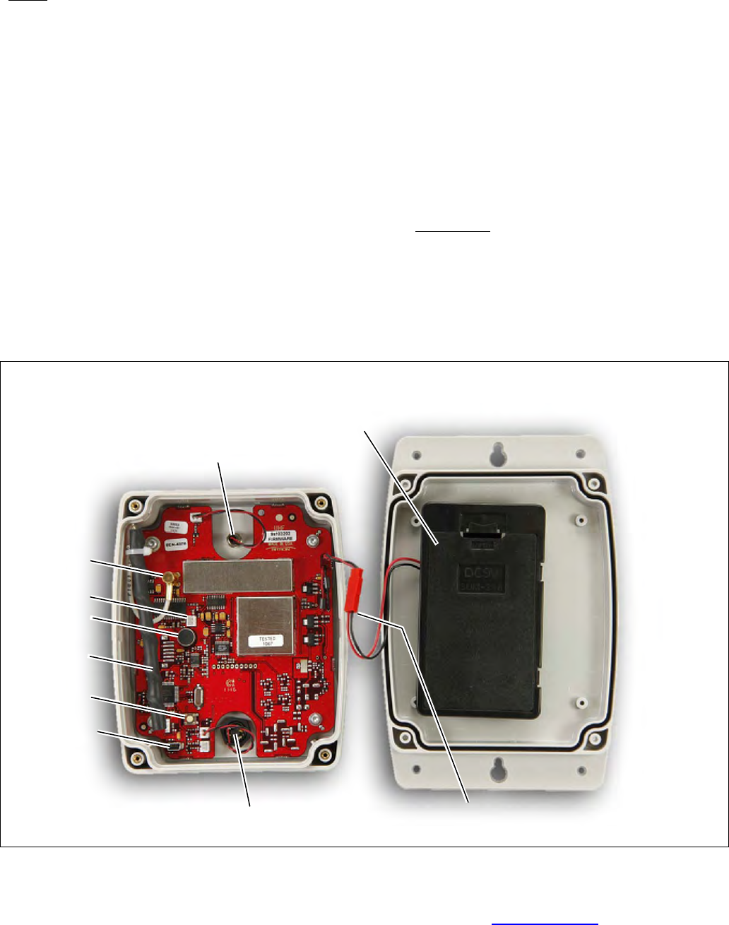
________________________________________________________________________________________________
For assistance, call RITRON at 800-872-1872, or go to www.ritron.com 12
IDENTIFICATION OF QUICK ASSIST® CONTROLS AND CONNECTIONS ..............................................................................................
1 Battery Holder
The battery holder accommodates the six (6) standard AA
alkaline cells required to power the Quick Assist®.
NOTE: Always install a fresh set of alkaline batteries
before programming the unit.
2 Front Panel LED
The red front panel LED is lit whenever the Quick Assist®
is transmitting a message.
3 SMB Antenna Connector
This connects the internal antenna to the radio printed
circuit board.
4 External Audio Input
Allows input to the Quick Assist® voice recorder from an
external audio source, such as the Line Out audio from
your computer.
5 Microphone
Microphone for recording voice messages.
6 USB Programming Connector
Connects the Quick Assist® to the USB port on your
computer for programming.
7 Record Button
Press this button to initiate voice recording.
8 Internal Antenna
The internal antenna radiates radio signals.
9 Front Panel Push Button
When the front panel push button is pressed the Quick
Assist® transmits your pre-recorded voice message. This
sealed push button provides a water-resistant enclosure.
10 Battery Connector
In-line connector between the printed circuit board and the
battery holder.
IMPORTANT: Do not remove any other fasteners or
further disassemble the Quick Assist® unit; doing so risks
damage to the unit and voiding the manufacturer’s
warranty.
FIG-1: CONTROLS & CONNECTIONS
1
2
3
4
5
6
9 10
7
8

________________________________________________________________________________________________
For assistance, call RITRON at 800-872-1872, or go to www.ritron.com 13
RITRON, INC. LIMITED WARRANTY................................................................................................................................................
WHAT THIS WARRANTY COVERS:
RITRON, INC. ("RITRON") provides the following warranty against defects in materials and/or workmanship in RITRON Radios and
Accessories under normal use and service during the applicable warranty period (as stated below). "Accessories" means antennas,
holsters, chargers, earphones, speaker/microphones and items contained in the programming and programming/service kits.
WHAT IS COVERED FOR HOW LONG WHAT RITRON WILL DO
Ritron RQA Quick Assist 1 year* During the first year after date of purchase, RITRON will repair or replace the
defective product, at RITRON's option, parts and labor included at no charge.
Accessories 90 days* *After date of purchase
WHAT THIS WARRANTY DOES NOT COVER:
• Any technical information provided with the covered product or any other RITRON products;
• Installation, maintenance or service of the product, unless this is covered by a separate written agreement with RITRON;
• Any products not furnished by RITRON which are attached or used with the covered product, or defects or damage from the use of
the covered product with equipment that is not covered (such as defects or damage from the charging or use of batteries other than
with covered product);
• Defects or damage, including broken antennas, resulting from:
- misuse, abuse, improper maintenance, alteration, modification, neglect, accident or act of God,
- the use of covered products other than in normal and customary manner or,
- improper testing or installation;
• Defects or damages from unauthorized disassembly, repair or modification, or where unauthorized disassembly, repair or
modification prevents inspection and testing necessary to validate warranty claims;
• Defects or damages in which the serial number has been removed, altered or defaced.
• Batteries if any of the seals are not intact.
IMPORTANT: This warranty sets forth the full extent of RITRON’s express responsibilities regarding the covered products, and is given
in lieu of all other express warranties. What RITRON has agreed to do above is your sole and exclusive remedy. No person is
authorized to make any other warranty to you on behalf of RITRON. Warranties implied by state law, such as implied warranties of
merchantability and fitness for a particular purpose, are limited to the duration of this limited warranty as it applies to the covered
product. Incidental and consequential damages are not recoverable under this warranty (this includes loss of use or time,
inconvenience, business interruption, commercial loss, lost profits or savings). Some states do not allow the exclusion or limitation of
incidental or consequential damages, or limitation on how long an implied warranty lasts, so the above limitations or exclusions may not
apply to you. Because each covered product system is unique, RITRON disclaims liability for range, coverage, or operation of the
system as a whole under this warranty.
WHO IS COVERED BY THIS WARRANTY: This warranty is given only to the purchaser or lessee of covered products when acquired
for use, not resale. This warranty is not assignable or transferable.
HOW TO GET WARRANTY SERVICE: To receive warranty service, you must deliver or send the defective product, delivery costs and
insurance prepaid, within the applicable warranty period, to RITRON, INC., 505 West Carmel Drive, Carmel, Indiana 46032,
Attention: Warranty Department. Please point out the nature of the defect in as much detail as you can. You must retain your sales
or lease receipt (or other written evidence of the date of purchase) and deliver it along with the product. If RITRON chooses to repair or
replace a defective product, RITRON may replace the product or any part or component with reconditioned product, parts or
components. Replacements are covered for the balance of the original applicable warranty period. All replaced covered products,
parts or components become RITRON’s property.
RIGHTS TO SOFTWARE RETAINED : Title and all rights or licenses to patents, copyrights, trademarks and trade secrets in any
RITRON software contained in covered products are and shall remain in RITRON. RITRON nevertheless grants you a limited non-
exclusive, transferable right to use the RITRON software only in conjunction with covered products. No other license or right to the
RITRON software is granted or permitted.
YOUR RIGHTS UNDER STATE LAW: This warranty gives you specific legal rights, and you may also have other rights which vary
from state to state.
WHERE THIS WARRANTY IS VALID: THIS WARRANTY IS VALID ONLY WITHIN THE UNITED STATES, THE DISTRICT OF
COLUMBIA AND PUERTO RICO.