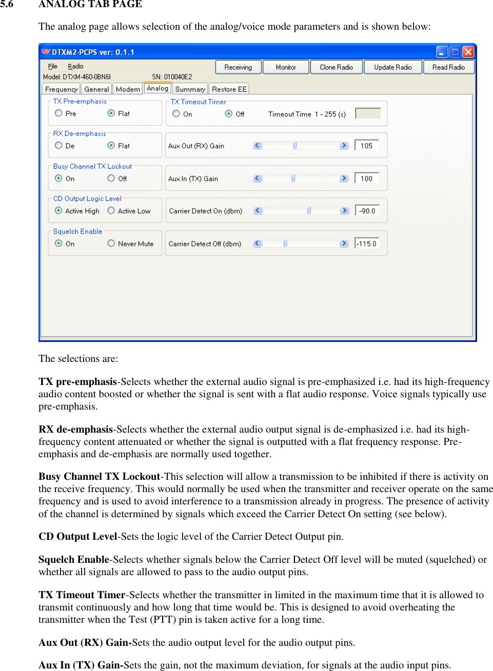
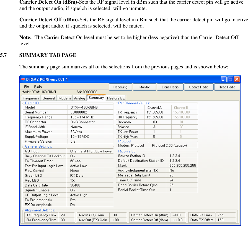
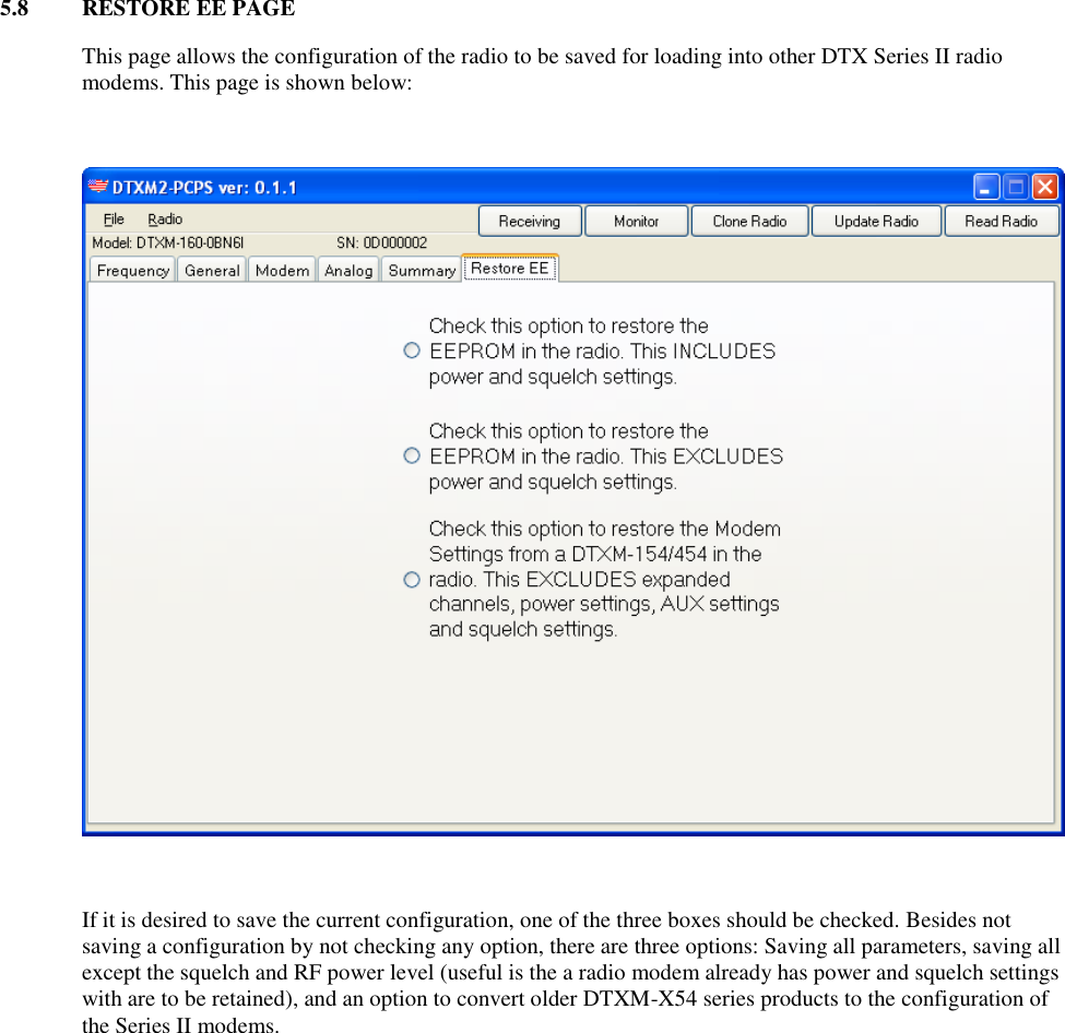
Ritron RIT39-16006 VHF Modem Module User Manual Rev

Ritron Inc VHF Modem Module Rev

Users Manual

Rev. 07/14       RITRON DTXM SERIES II DTXM-X60 FAMILY  PROGRAMMABLE WIRELESS FM  MODEM TRANSCEIVERS  VHF/220 MHz/340-400 MHz/UHF  6.25 kHz/12.5 kHz/25 kHz Channels  Multiple Protocol
1  INTRODUCTION  1.1  GENERAL  The DTX Plus Series II modem is a wireless modem designed to operate on the frequency bands at VHF, UHF, and 220 MHz.  It supports over-the-air data rates of 4800 bps in a 5.0/6.25/7.5 kHz channel, 9600 bps in a 12.5/15 kHz channel, and 19.2 kbps in a 25/30 kHz channel.  The modem supports three protocols, the legacy packet protocol of the DTXM-X54 series, a small-packet streaming protocol, and a no-overhead streaming protocol with no error detection/correction. Besides offering data communications, the DTX Plus modem includes voice transceiver audio input and outputs.  The complete modem transceiver is housed in the standard DTX Plus case, resulting in a light, compact package.    1.2 MODEL IDENTIFICATION  The DTX Plus modem has a part number in the form of “DTXM-A60-BCDEF”  Where:   A is the major frequency band designator:    1=VHF (136-174 MHz)   2=217-245 MHz   3=340-400 MHz   4=UHF (400-520 MHz)  B is the sub-band designator:   G=340-360 and 400-420   A=420-440   B=430-450   0=136-174, 217-245, 360-380, and 450-470   M=380-400   C=470-490   T=490-512  C is the connector designator:    B=BNC connector   M= MCX connector   S=SMA connector  D designates the channel bandwidth:    S=6.25 kHz   N=12.5 kHz   W=25 kHz  E designates the maximum power level:    3=3 watts   6=6 watts   9=10 watts
F designates the regulator option    I=Internal regulator (10-16 VDC operation with regulated RF power amplifier)   D=No regulator (7.5 VDC operation)   L=RF PA is unregulated, but the remainder of the modem is regulated (10-watt versions)   Example:  A DTXM-460-OBN6I would be a UHF module for operation between 450 and 470 MHz with a BNC RF connector, narrow (12.5 kHz channel spacing) IF bandwidth, 6 watts maximum output power, and an internal regulator to allow operation from 10 to 15 volts.  1.3  FCC REGULATIONS  1.3.1  Licensing  The FCC requires that the radio owner obtain a station license for his radio before using the equipment to transmit, but does not require an operating license or permit.  The station licensee is responsible for proper operation and maintenance of his radio equipment, and for ensuring that transmitter power, frequency and deviation are within the limits specified by the station license.  This includes checking the transmitter frequency and deviation periodically using appropriate methods.    1.3.2  Equipment Authorization (Certification)  At the time of this publication, March, 2014, none of the DTXM-X60 series products have been certified and thus, cannot be operated in those bands/countries that require an equipment authorization.  This device has not been authorized as required by the rules of the Federal Communications Commission. This device is not, and may not be, offered for sale or lease, or sold or leased, until authorization is obtained.  1.3.3  Radio Frequency Exposure   The FCC, with its action in General Docket 79-144, March 13, 1985, adopted a safety standard for human exposure to radio frequency electromagnetic energy emitted by FCC regulated equipment.   The DTXM product family has been evaluated for compliance with the maximum exposure limits for RF energy at the maximum power rating of the unit and with the only antenna sold for use with this product by RITRON.  To ensure compliance with the General Population/Uncontrolled maximum exposure limits, please observe the following: When the Ritron RAM-1545 remote magnetic mount antenna is used, mount the antenna in a location that will ensure that all persons will be located away from the antenna by the following minimum distances:  Model        Minimum Distance  DTXM-160-0BX6    13.7 in. (34.8 cm) DTXM-260-0BX6       DTXM-460-0BX3      5.7 in. (14.4 cm) DTXM-460-0BX6      6.4 in. (16.2 cm) DTXM-460-0BX9      8.3 in. (21.0 cm) Antennas other than the Ritron RAM-1545 must be tested with the DTXM for RF exposure compliance in the environment in which it is to be used per the FCC’s OET Bulletin 65, Edition 97-01 or Industry Canada RSS-102.
2  SPECIFICATIONS   2.1  GENERAL  FCC Rule Parts           90 IC Rule Parts          RSS-119 Data rate (bps)   6.25 kHz channel       4800 bps 12.5 kHz channel       9600 bps 25 kHz channel        19,200 bps         Modulation Voice          Direct FM Data          4FSK   Over-the-Air Protocols        Ritron Proprietary     Number of Channels        2 Operating Bandwidth VHF     38 MHz 220 MHz        28 MHz 340-400 MHz        20 MHz 400-430 MHz        30 MHz UHF          20 MHz Synthesizer Step Size   VHF          2.5 kHz 220 MHz        2.5/3.125 kHz 300-430 and UHF      5.0/6.25 kHz Emissions Bandwidth Voice  Not allowed   12.5 kHz channels    10.0 kHz   25 kHz channels      15.0 kHz Data   6.25 kHz channels    4.0 kHz   12.25 kHz channels    8.0 kHz   25 kHz channels      16.0 kHz Frequency Stability -30°C to +60°C        +/- 1.0 ppm -30°C to +75°C    +/- 1.5 ppm Supply Voltage D-version        7.5+/-0.5 VDC I, L-versions        11-16 VDC RF Connector          BNC (optional MCX and SMB) Power/Data Connector        15-pin subminiature D-type Dimensions (LxWxH)        3.6”x 2.3” x1.0” Weight            6 oz Indicators          Transmit LED, Receive LED  2.2  TRANSMITTER  RF Output Power      VHF,220 MHz, 300-430 MHz    1-6 watts UHF          1-3 watts, 1-6 watts, 2-10 watts RF Load Impedance        50 ohms resistive, VSWR 1.5:1 or less PTT attack time          10 ms max. Spurious and Harmonics        -25 dBm max.
FM Hum and Noise 6.25 kHz channel       35 dB min. 12.5 kHz channel       40 dB min. 25 kHz channel        45 dB min. Current Drain 1 watt          1.1 A max. 2 watts          1.6 A max. 6 watts          2.2 A max. 10 watts         2.6 A max.   2.3  RECEIVER  Sensitivity Voice  (12 dB SINAD)      0.25 uV max. Data  (10-3 BER)        0.30 uV max. Adjacent Channel Selectivity 6.25 kHz channel       50 dB min. 12.5 kHz channel       60 dB min. 25 kHz channel        70 dB min. Spurious and Image Rejection      70 dB min. IMD Rejection          67 dB min. FM Hum and Noise 6.25 kHz channel       35 dB min. 12.5 kHz channel       40 dB min. 25 kHz channel        45 dB min. Conducted Emissions        -57 dBm max. Squelch Attack Time      15 ms max. Receive Current Drain      120 mA max.
3  DTXM I/O CONNECTOR AND INDICATORS  3.1  15-PIN I/O CONNECTOR  Connector Pinout  Pin   Name    Description      Comments  1  AUDIO_IN  Input    Input for Audio to be transmitted in Voice mode 2  AUDIO_OUT  Output    Line level receiver audio output 3  SPEAKER  Output    Receiver audio output to drive a speaker 4  A/B    Input    Channel 1/2 or High/Low power 5  NC        Not Used 6  Supply    Input    DC Power + input connects here to power unit 7  NC    Output    Receiver Alignment-Do NOT CONNECT 8  RD    Output    RS-232 data output from modem 9  TD    Input    RS-232 data input to the modem 10  CTS    Output    RS-232 clear to send output from modem 11  DSR    Output    RS-232 data set ready output from modem 12  TEST    Input    Used for PTT in voice mode 13 CD    Output    Carrier detect 14  RTS    Input    RS-232 request to send input to modem 15 GND        System ground, - power supply input connects here  Pinout Description   Pin 1    AUDIO_IN  This is the input for signals to be transmitted when the unit to be operated in the voice/analog mode.  The actual transmission is initiated by asserting the TEST pin (pin 12).  The polarity and modulation sensitivity for signals at this pin can be set via the programmer.  The input resistance at this pin is greater than 10 k and is AC coupled. Note that this pin is only active on the 12.5 kHz channel bandwidth models, NOT on the 6.25 kHz channel bandwidth models.  Pin 2    AUDIO_OUT  Amplified, buffered, and filtered receiver audio is present at this output.  The audio level can be adjusted via the programmer as well as the choice of a flat vs de-emphasized frequency response.  The presence of audio at this pin is controlled by the squelch (carrier detect) settings, also adjustable via the programmer.  Pin 3    SPEAKER  This output is similar to the AUDIO_OUT signal above except that it is always de-emphasized and is able to drive an 8-ohm speaker load.  The level is adjustable via the programmer with the same setting as that which sets the AUDIO_OUT level.  Pin 4    A/B  Depending on how it is programmed via the programmer, this pin can either be a channel A/channel B selection pin or a high/low transmit power selection pin.  This pin has an internal pullup resistor to +5 volts and assumes a high (channel A or high power) state when left unconnected.  Pin 5    Not Used  Pin 6    SUPPLY
 This is the positive power supply input for the modem.    Pin 7    Receiver Alginment  This pin is the output pin of the modem IC’s input operational amplifier.  It is used during alignment to set the receiver gain and DC offset for proper modem IC receiver decoding. This pin must be left unconnected by the user!   Pin 8    RD (Receive Data)  RS-232 data to be received from the modem is available at this pin.  The data are at normal RS-232 levels and are transmitted from the modem to be received by the host computer or other device connected to the modem.   Pin 9    TD (Transmit Data)  RS-232 data to be transmitted to the modem should be presented to this pin.  The data should be at normal RS-232 levels and are transmitted from the host computer or other device to the modem.  Pin 10    CTS (Clear to Send)  This RS-232 output pin is asserted by the modem as a response to an assertion of the RTS pin when it is ready and able to receive data from the host computer or device.  Pin 11    DSR (Data Set Ready)  This RS-232 output pin is asserted by the modem when it is powered-up.  It indicates that the modem is actually connected, although not necessarily ready to receive data.  The polarity (active low/active high) is programmable via the programmer.  Pin 12    TEST (Voice mode PTT)  This pin in used to key the transmitter.  When asserted (taken low), this pin activates the voice/analog transmit audio path and keys the transmitter, or transmits data test patterns.  Pin 13    CD (Carrier Detect)  This pin is asserted by the modem when the receiver has detected a carrier.  The RF level for CD assertion is set via the programmer.  Note that the modem demodulation circuitry does not actually use this signal to determine that a valid data packet has been received.  The polarity (active low/active high) is programmable via the programmer  Pin 14    RTS (Request to Send)  This RS-232 input pin is asserted by the host computer or device to indicate that it has data to be transmitted by the modem.  If the modem is able to accept the data, the CTS pin will be asserted in response.   Pin 15    GND (Ground)  The system ground common point and negative connection for the power supply input.
3.2  INDICATORS  The DTXM Modem has two indicators on the side of the unit, one green RX LED and one red TX LED.  They function as follows: GREEN RX LED-This LED can be programmed to be illuminated under a variety of conditions. The choices are: Never (Off), whenever power is applied (Power On), when receiving, whether or not an actual signal is on the frequency (RX Synthesizer Lock), and when receiving and an actual data packet is being received (RX Data). In typical applications, either RX Synthesizer Lock or RX Data is selected. RED TX LED-This indicator can be programmed to be illuminated when the modem is transmitting, regardless of whether the unit is transmitting data or voice or to be never illuminated.
4  OPERATION   4.1  CHANNEL SELECTION  Via the 15-pin connector, the DTXM supports one channel if the A/B pin (pin 4) is programmed for high/low power and two channels if the A/B pin is programmed as a channel select input.  Channel A is set when the A/B pin is activated and the A/B pin is in the logic high state i.e. above 2.0 volts DC or left unconnected (There is an internal pullup resistor on the A/B pin).  Channel B is set when the A/B pin is activated and the A/B pin is in the logic low state i.e. below 0.5 volts DC.  If the A/B pin is programmed for high/low power, channel A is always selected.  A change in the channel selection in receive will cause the receiver to operate on the new channel.  In transmit, however, the channel selection is only checked only at the beginning of a transmission.  Changes in channel during transmit will not change the transmit operating channel of the unit until the unit is cycled from transmit to receive and back to transmit.  4.2  POWER SUPPLY VOLTAGE  The DTXM-160, DTXM-260, DTXM-360  units and the 3 and 6-watt DTXM-460  units use 7.5 volt RF power modules.  Two supply voltage options are available for these units depending upon whether the control/loader board has a regulator installed.  If a regulator is not installed, the voltage should be 7.5 volts +/-10 %.  This voltage should be “clean” and preferably regulated since the RF power module is powered directly from this source.  Variations in voltage will cause variations in transmitted output power.  Conversely, if the control/loader board has a regulator installed, the supply voltage can be at any voltage between 11 and 16 volts.  The RF power module in the 10 watt DTXM-460 unit requires at least 12 volts to achieve 10 watts, although voltages as high as 15 may be used.  Since the module is powered directly from this voltage, the supply should be “clean” and, preferably, regulated.  The output power will vary with supply voltage.  Switching power supplies can be used, but in models without the internal regulator, care must be taken that the output waveform is low noise.  Also, the module antenna should never be placed near an unshielded switching power supply.    4.3  CURRENT DRAIN VS SUPPLY VOLTAGE    The current drain of the module is a function of the supply voltage, the RF output in transmit and the regulator option.  The internal 7.5-volt regulator is a switching type such that the current drain actually decreases with an increase in supply voltage.  Typical current drain values are shown in the table below:  Receive Mode   Supply Voltage    Internal Regulator  Current Drain   7.5 V        No    130 mA 11.0 V        Yes    100 mA 12.5 V        Yes      90 mA 16.0 V        Yes      75 mA  Transmit Mode – 1 watt output power  Supply Voltage    Internal Regulator  Current Drain   7.5 V        No    1.2 A 11.0 V        Yes    0.9 A 12.5 V        Yes    0.7 A 16.0 V        Yes    0.5 A
 Warning:  Although the output power can be set as low as 1 watt, and the module is certified as low as 1 watt, operation below 2.5 watts output power is not recommended.  At low power levels, the output power can vary by 50% or more with variations in ambient temperature.    Transmit Mode – 3 watt output power  Supply Voltage    Internal Regulator  Current Drain   7.5 V        No    1.8 A 11.0 V        Yes    1.4 A 12.5 V        Yes    1.2 A 16.0 V        Yes    0.9 A  Note:  The 3-watt version of the DTXM-460 operates more efficiently than the 6-watt version with power reduced to 3 watts.  Therefore, the current drain values for the 3-watt version of the DTXM-460 will be about 80% of the values shown above.  Transmit Mode – 6 watt output power  Supply Voltage    Internal Regulator  Current Drain   7.5 V        No    2.5 A 11.0 V        Yes    2.1 A 12.5 V        Yes    2.0 A 16.0 V        Yes    1.5 A  Transmit Mode – 10 watt output power (10-watt version of DTX-460 only)  Supply Voltage    Internal Regulator  Current Drain  13.5 V      RF PA is unregulated  2.5 A   4.4  DUTY CYCLE/KEY-DOWN LIMITATIONS  The major heat generating component within the modules is the RF power amplifier which has a maximum temperature limit that should not be exceeded.  In addition, the temperature within the module itself must be kept below the maximum temperature of the reference oscillator to ensure that regulatory frequency stability limits are observed.  As a result, depending upon the RF output power, the supply voltage, and the ambient temperature, limits upon the average transmit duty cycle and the maximum continuous transmitter on time exist.  These limits are summarized below for operation in still air:  Ambient Temperature (C)  Duty Cycle (%)     Key-Down Time (s)   3 watts RF output   25        30    45  50        5    10  6 watts RF output   25        20    30  50        3    5  10 watts RF output  25        20    15  50        3    5
Blowing air across the unit and/or adding a heat sink to the rear of the unit where the PA module is located can significantly improve the duty cycle/key-down times.  Ritron offers an option where the case screws at the rear of the module are longer allowing heat sinks to be attached.  Also, a fan option is available from Ritron which can significantly increase the duty cycle, up to 100% at room temperature in some cases. Contact Ritron for additional information on these options and special instructions on attaching heat sinks without compromising the mechanical integrity of the RF PA module.
4.5  INSTALLATION  The DTXM modem has two connectors, a BNC for the RF (Antenna) connection and a 15-pin D-subminiature for the data/programming interconnection. The BNC connector should be connected to a suitable antenna or RF dummy load or attenuator, depending upon the installation. If an antenna is connected, it should be placed at least 10 ft. away from the radio itself to prevent RF interference. Also, any antenna must present a good 50-ohm RF load (low VSWR) at the operating frequency. The 15-pin connector is usually used with a Ritron programming cable which provides for DC power connections and a serial connection for programming and for the data to transmitted and received. 5.0  PROGRAMMING THE MODEM The operating parameters of the DTXM modem can be set and adjusted via the Ritron DTXM-X60 series programmer, DTXM2-PCPS. Note that the programmer for the previous Ritron wireless modem, i.e. the DTXM-X54 series will NOT work with this product. The programming software should be loaded on a host computer by loading the CD-ROM disc into the host computer’s appropriate drive. The programming software itself should be self-extracting. If it does not load automatically, it can be manually loaded by running “Setup.exe” on the CD Rom.  The Ritron modem should be connected to the host computer by the 9-pin connector. The red wire in the cable should be connected to positive supply voltage for the modem while the black should be connected to the negative side. The voltage itself should be compatible with that required by the modem. In programming mode, the current required by the modem is about 150 mA and the power supply should be capable of supplying that current. Note that in transmit, it can be much, much higher, 2 to 3 amperes is not unusual. It is possible to transmit with the programmer program running, but the power supply must be able to supply the necessary current and a suitable RF load must be provided on the BNC connector. Once the modem is connected to the host computer and a power supply is connected, the programming software program can be opened and the power supply turned on.The first screen to become visible is the “welcome” screen shown below: .
The button at the upper right is the Programmer Configuration button and is used to set the serial communications baud rate for communications between the programmer and the host computer. It defaults to 38400 baud, but can be set to other common serial rates. In addition, if the host computer baud rate is unknown, the Test Configuration button can be selected to auto-detect the baud rate. Selecting OK confirms the choice of baud rate.   The other button is used to read the contents of the radio into the programmer so that the current configuration of the radio can be observed and edited. 5.1  FREQUENCY TAB Upon selecting the Read Radio button, the Frequency tab is opened as shown below.      This page shows the frequencies programmed into the modem. Depending upon how the A/B pin is programmed either one or two pairs of frequencies will be displayed. Frequencies can be programmed into the device by clicking on the appropriate field and typing in the desired frequencies. The frequencies must be within the operating range of the radio and must be divisible by the synthesizer step size for the
particular model use. In addition, there are five other tabs and five buttons that can be selected. These are summarized below: 5.2  PAGE TABS  The page tabs show up on all of the pages. Clicking on a tab moves one to that page.   Frequency-as explained above, this page allows the observing and entering of operating frequencies.   The other tabs are shown below and their contents will be detailed in later sections.  General-shows the general operating parameters of the modem.   Modem-shows the modem parameters such as protocol, etc.   Analog-shows the parameters of the analog/voice path.   Summary-shows all of the parameters of the modem on one page.   Restore EE-allows the configuration of the programmed radio modem to be saved.  5.3  BUTTONS  There are five buttons which show up on all of the pages. These are: Receiving-This is a software (programmer) PTT selection. Selecting this button will put the radio modem in transmit mode, regardless of the state of the PTT pin. Selecting this button again will return the radio back to receive.    Monitor- This is a software (programmer) Monitor selection. Selecting this button will unmute theanalog/voice receiving path of the radio modem. Selecting this button again will return the radio back to normal squelched operation. Note that if unsquelched operation is selected on the Analog page, this button will have no effect.  Clone Radio-This allows the radio parameters to be copied into another radio.  Update Radio-Loads the programmer’s parameters into the radio. Note that changes made via the programmer are NOT permanently saved into the radio until this button is selected. The radio’s behavior will change as changes are made via the programmer, but will be lost on power-down unless, and until, this selection is made.  Read Radio- Reads the radio modem’s parameters into the programmer for observation and editing.
5.4  GENERAL TAB PAGE   The General Page is shown below:  The selections are:  A/B Input One or Two Channel-Determines the function of the A/B pin. This pin can be used to control the power selection, high or low, for one channel, channel A or it can be used to choose between channel A and channel B, in which case, the output power is high for both. Comm Port Baud Rate-Determines the baud rate for communications between the data device and the radio modem. This number should match that shown on the Programmer Configuration screen. Test Pin Input Logic Level (PTT)-Determines the polarity of the test pin. The test pin is used to put the radio in transmit in analog/voice mode or to send test patterns in modem mode. This pin has an internal pullup resistor and thus, assumes a logic high state when not connected. Therefore, active low is the normal, default setting. Red LED-Determines the behavior of the Red LED indicator. The choices are that it can be set to never be illuminated or illuminated when the radio is transmitting. CD Output Logic Level-Determines the polarity of the CD (Carrier Detect) output pin.  Green LED-Determines the behavior of the Red LED indicator. The choices are for it to never be illuminated (off), be illuminated whenever the radio is powered (Power On), when the receiver is locked and receiving (RX Synthesizer Lock), or data/analog information is being received (RX Data). In the latter mode, the indicator would come on whenever one of two conditions is met, the squelch level (carrier detect level) is exceeded, even when Squelch is never muted, or when the receive data has detected a valid data stream.
TX Low Power/TX High Power-This allows setting the RF output power for the two states of the low/high power pin. The low-power selection corresponds to the low logic level of the pin while the high-power selection corresponds to the high logic level. Note that the high-power selection does not necessarily have to be greater than the low-power selection. Each is independent of the other and only corresponds to a state of the power select pin. Per Channel Values-Summarizes the high and low power settings for the channels used by the radio. 5.5  MODEM TAB PAGE    The modem page allows selecting the parameters of the modem mode operation and is shown below:    The selections are:  Modem Protocol-This selects the over-the-air protocol. The three choices are detailed below: Low Latency Protocol with no CRC-This is as close to a bit in/bit out protocol which can be supported by the Ritron radio modem. A synchronization pattern is affixed to the beginning of the transmitted stream, but after that, each symbol transmitted directly corresponds to two input bits. No error detection or correction is used within the protocol itself. This protocol provides for the fastest overall data rate, but sacrifices data accuracy. Virtual Streaming Protocol-This is similar to the low latency protocol, but the data is divided into blocks and an error detecting CRC word is added to each block. This word is removed before the data is passed to the data device on the receiving end. Blocks with errors are not passed on to the data device. Protocol 2.00 (Legacy)-This is the protocol used by the DTXM-X54 family. This is a very robust, packet protocol useful for large data blocks, but not for fast streaming or fast polling. This protocol is useful when interfacing a system with the legacy Ritron DTXM-X54 family and/or when data errors cannot be tolerated.
Test Patterns (via Test Pin)-Selecting any of the selections in this box will cause a test pattern to be transmitted when the Test Pin (PTT) is active. If no selection is made, activating the Test Pin will cause the radio to transmit in analog/voice mode. The choices are: Bit Error Rate (BER)-A pn pattern is generated which allows for the computation of bit error rate, setting deviation, or observing an eye pattern. The pattern is 511 symbols long with no synchronization symbols and repeats continually. It is a maximal length pattern with feedback taps at the 5 and 9 bit positions. Send Test Pattern-A packet which transmit over and over with a constant data structure. This pattern can be used to test the system in the low latency and streaming modes. Square Wave Generator-Transmits a 400 Hz square wave. Used to set the deviation and modulation balance during alignment or to hear the transmitted 400 Hz tone on a receiver or radio modem in analog/voice mode. TX Carrier Mode-An unmodulated carrier is transmitted.  Protocol 2.00-The items is this box select the identification parameters used in the legacy 2.00 protocol.  Source Station ID-Source Station ID-Sets the address of the modem itself.  It is made up of 4 parts, from most general to most specific: System ID, Group ID, Unit ID, and Sub-unit ID.  Default Destination ID-Sets the destination ID of the intended recipient.  Protocol Mask-The protocol mask determines how close a mask must exist between the modem’s ID and the destination ID in the message before accepting and outputting to the host the message.  A ‘1’ for any location in the mask requires a perfect match, while a ‘0’ means a ‘don’t care’ situation.  This is useful for ‘broadcast’ i.e. one unit transmitting to more than one unit situation.  Note:  In broadcast applications, the ‘Acknowledgement after TX’ selection should NOT be selected to prevent multiple units from responding and interfering with each other. See below. Configuration- Acknowledgement required after transmit-When checked, the modem requires an acknowledgement after each transmission or the transmission will be repeated.   Message Retry Limit and Timeout Time-The amount of time in ms that the modem will wait for an acknowledgement and the number of times it will repeat a message can be set in the Message Retry Limits box and the Time Out Time boxes Dead Carrier before Symbol Sync-The amount of time in ms that an unmodulated carrier will exist before the beginning of the symbol sync pattern. Partial Packet Timeout-The amount of time in ms of no data from the data device that must exist before a packet is formed and transmitted.
5.6  ANALOG TAB PAGE    The analog page allows selection of the analog/voice mode parameters and is shown below:      The selections are: TX pre-emphasis-Selects whether the external audio signal is pre-emphasized i.e. had its high-frequency audio content boosted or whether the signal is sent with a flat audio response. Voice signals typically use pre-emphasis. RX de-emphasis-Selects whether the external audio output signal is de-emphasized i.e. had its high-frequency content attenuated or whether the signal is outputted with a flat frequency response. Pre-emphasis and de-emphasis are normally used together. Busy Channel TX Lockout-This selection will allow a transmission to be inhibited if there is activity on the receive frequency. This would normally be used when the transmitter and receiver operate on the same frequency and is used to avoid interference to a transmission already in progress. The presence of activity of the channel is determined by signals which exceed the Carrier Detect On setting (see below). CD Output Level-Sets the logic level of the Carrier Detect Output pin. Squelch Enable-Selects whether signals below the Carrier Detect Off level will be muted (squelched) or whether all signals are allowed to pass to the audio output pins. TX Timeout Timer-Selects whether the transmitter in limited in the maximum time that it is allowed to transmit continuously and how long that time would be. This is designed to avoid overheating the transmitter when the Test (PTT) pin is taken active for a long time. Aux Out (RX) Gain-Sets the audio output level for the audio output pins. Aux In (TX) Gain-Sets the gain, not the maximum deviation, for signals at the audio input pins.
Carrier Detect On (dBm)-Sets the RF signal level in dBm such that the carrier detect pin will go active and the output audio, if squelch is selected, will go unmute. Carrier Detect Off (dBm)-Sets the RF signal level in dBm such that the carrier detect pin will go inactive and the output audio, if squelch is selected, will be muted. Note:  The Carrier Detect On level must be set to be higher (less negative) than the Carrier Detect Off level. 5.7  SUMMARY TAB PAGE    The summary page summarizes all of the selections from the previous pages and is shown below:
5.8  RESTORE EE PAGE  This page allows the configuration of the radio to be saved for loading into other DTX Series II radio modems. This page is shown below:      If it is desired to save the current configuration, one of the three boxes should be checked. Besides not saving a configuration by not checking any option, there are three options: Saving all parameters, saving all except the squelch and RF power level (useful is the a radio modem already has power and squelch settings with are to be retained), and an option to convert older DTXM-X54 series products to the configuration of the Series II modems.

Navigation menu