Ritron RIT41-417 UHF-FM Callbox 2-Way Radio User Manual TABLE OF CONTENTS
Ritron Inc UHF-FM Callbox 2-Way Radio TABLE OF CONTENTS
Ritron >
Users Manual

Have questions? Call 800-USA-1-USA (800-872-1872) or visit our website at www.ritron.com 0
T
ABLE OF
C
ONTENTS
............................................................................
Basic Operation
XD-SERIES CALLBOX MODELS ................................................. 1
ABOUT THE XD-SERIES CALLBOX ............................................. 2
EXPOSURE TO RADIO FREQUENCY ENERGY ............................... 3
OPERATING THE XD-SERIES CALLBOX WITH
FACTORY DEFAULT SETTINGS .................................................. 3
Installation Instructions
APPLYING POWER TO THE XD-SERIES CALLBOX ........................ 4
Using Internal Batteries ......................................................... 4
External Antenna Connector and Antenna Jumper Settings ....... 4
Using External 8 to 12 VDC Power with Battery Back-up ............. 5
Using External 8 to 12 VDC Power without Battery Back-up ........ 5
POWER MANAGEMENT OPTIONS ............................................... 6
FIG-1
: Sensor Turn-On Jumper Shown in Turn-On Position
.............. 6
CALLBOX CONTROLS AND CONNECTORS ................................... 7
FIG-2: Callbox Assembly, Controls and Connectors .................. 8
XD-SERIES CALLBOX INSTALLATION INSTRUCTIONS .................... 8
OPTIONAL XD-SERIES CALLBOX PEDESTAL MOUNTING BRACKET
INSTALLATION INSTRUCTIONS .................................................... 8
OPTIONAL XD-SERIES EXTERNAL ANTENNA INSTALLATION
INSTRUCTIONS ...................................................................... 10
Field Programming
RQX FIELD PROGRAMMING OVERVIEW ................................... 11
HOW TO FIELD PROGRAM FREQUENCY & TONE CODES ............. 12
TABLE 1: PROGRAMMABLE FREQUENCY CODES ....................... 13
CANADIAN FREQUENCY CODES ........................................... 13
TABLE 2: PROGRAMMABLE QC TONE CODES ........................... 14
TABLE 3: PROGRAMMABLE DQC TONE CODES ........................ 14
HOW TO FIELD PROGRAM 2-TONE, DTMF OR SELCALL DECODE
(RECEIVE) OPERATION .......................................................... 15
TABLE 4: PAGING, GATEGUARD® AND LISTEN IN DECODE
CODES ................................................................................. 17
HOW TO FIELD PROGRAM DTMF OR SELCALL ENCODE ANI
(TRANSMIT) CODES ............................................................... 19
HOW TO FIELD PROGRAM FEATURE CODES ............................. 20
TABLE 5: ADVANCED FEATURE CODES .................................... 21
Programmable Features
PC PROGRAMMABLE XD-SERIES CALLBOX FEATURES ............. 23
Glossary of Terms .............................................................. 23
TABLE 6: PC PROGRAMMABLE FEATURES ............................... 24
INTERCOM (ALWAYS-ON) PROGRAMMING ................................ 25
FEATURES TO USE WITH INTERCOM (ALWAYS-ON)
PROGRAMMING ..................................................................... 25
SWITCH OUTPUT OPTIONS (ALLOWS CONTROL OF AN EXTERNAL
DEVICE) ............................................................................... 26
2-TONE, DTMF OR SELCALL DECODE (RECEIVE) SETTINGS
............................................................................................ 26
Voice Messages
AUTOMATIC VOICE MESSAGES ................................................ 27
AUTOMATIC ID RE-SEND ........................................................ 28
HOW TO RECORD A VOICE MESSAGE) ..................................... 29
HOW TO PLAY A VOICE MESSAGE ........................................... 30
HOW TO ERASE A VOICE MESSAGE ......................................... 30
GateGuard® Application
Configuration for the Remote Control of a Gate Controller
CONFIGURING THE CALLBOX FOR A GATEGUARD® APPLICATION 31
TABLE 7: CALLBOX 6-CONDUCTOR INTERFACE CABLE ............... 32
INSTALLING THE CALLBOX 6-CONDUCTOR INTERFACE CABLE ..... 33
HOW TO FIELD PROGRAM THE XD-SERIES CALLBOX FOR
GATEGUARD® OPERATION ..................................................... 33
OPTIONAL GATEGUARD® SETTING/FEATURES ......................... 33
NXDN Setup
HOW TO FIELD PROGRAM NXDN FEATURES ............................ 35
NXDN PROGRAMMING CODES ................................................ 35
HOW TO SET NXDN CALLBOX SUID AND OTHER IDS ................ 36
Licensing
FCC Licensing ....................................................................... 37
How to Obtain an FCC Radio License ....................................... 37
INDUSTRY CANADA Regulations............................................ 37
Safety Standards ................................................................... 37
Service ................................................................................. 37
Warranty
RITRON, INC. LIMITED WARRANTY ....................................... 38
THANK YOU FOR CHOOSING RITRON
Congratulations on your purchase of the RQX XD-Series
Callbox Your new radio is the culmination of RITRON’s 35
years of designing, manufacturing, and supplying reliable,
professional wireless communication products. Ritron
wireless products will improve the operation, safety, and
profitability of any organization by providing instant voice
communications between employees throughout the
workplace.
RQX XD-Series Wireless Callbox Basic Operation
Have questions? Call 800-USA-1-USA (800-872-1872) or visit our website at www.ritron.com 1
XD-S
ERIES
C
ALLBOX
M
ODELS
.............................................................
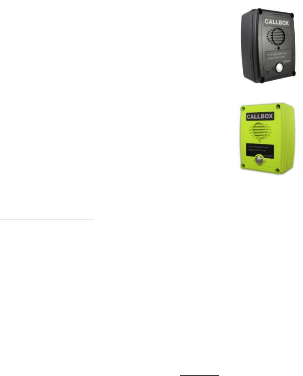
XD-Series Models
VHF:
RQX-117NX
RQX-117NX-CANADA
UHF:
RQX-417NX
RQX-417NX-CANADA
The XD-Series callbox is programmable to operate as an analog FM two way radio or as an
NXDN digital voice two way radio. This allows user to transition to digital voice as needed. The
NXDN capability is contained in a piggy back board that connects perpendicular to the main
board. The XD-Series callbox is available in both the standard model high visibility green
enclosure, and in the -BLK model black enclosure.
The model number appears on the serial label located on the back of the XD-Series Callbox
enclosure.
VHF radios are designed to operate within the 15 MHz band between factory standard 150 to
165 MHz.
UHF radios are designed to operate within the 20 MHz band between factory standard 450 to
470 MHz.
Advanced Features available with the XD-Series models include 2-Tone, DTMF, Selcall and
NXDN Decode, Voice Messages, Analog Companding, Sensor Input, and a Relay Switch
Closure.
NXDN digital Features are based on RAN and ID codes and perform similar functions as the
analog addressing modes. The Ritron programmer will aid in PC set up of these features. Manual
set up of these features can be seen in under
HOW TO FIELD PROGRAM NXDN
FEATURES
The Power supply to the XD callbox can be three internal D cells or an external 8 to 12 VDC input or both. It is important to use
new good quality D cells. See “Applying power to the XD-Series Callbox”.
OPTIONAL ACCESSORY EQUIPMENT
Several options are available for the Ritron XD-Series Callbox. These options, individually, or in combination with one another can
greatly enhance the functionality of the callbox as well as the overall communication system. Available options include:
RSS-100 - The RSS-100 is a complete solar power supply system consisting of a 10-watt solar panel, charge controller and 8
AH rechargeable battery all housed in a rugged, ready-to-mount enclosure.
R-STROBE - The R-STROBE is a powerful strobe light, giving a visual indication of a callbox in use. The R-STROBE is
available in both AC (R-STROBE) and DC versions (R-STROBE-DC). If used the XD callbox must be externally powered.
RCIM-1000 - The RCIM-1000 MDC-1200 encoder board allows each callbox to be assigned a unique unit ID number. If used
the XD callbox must be externally powered due to space restrictions.
For additional information and pictures of these items go to http://www.ritron.com/callboxes.html and download pdf of the product
brochure.
XD-Series Callbox-
es

RQX XD-Series Wireless Callbox Basic Operation
Have questions? Call 800-USA-1-USA (800-872-1872) or visit our website at www.ritron.com 2
A
BOUT THE
XD-S
ERIES
C
ALLBOX
...........................................................
The XD-Series Callbox is a 2-way radio transceiver used to communicate directly with portable, mobile and stationary analog FM or
NXDN digital radios; or through radio repeaters with Ritron PC Programming software. Each callbox is equipped with the following
features or capabilities.
Field Programming. Field programming allows you to quickly program your radio in the field without the need for a PC
programmer. Each radio can be field programmed to one of 27 VHF or 114 UHF channel table frequencies, and one of 50 QC
or 104 DQC interference eliminator codes.
154 Interference Eliminator Codes. Quiet Call (QC) and Digital Quiet Call (DQC) codes can be programmed to eliminate
other radio users not in your workgroup. For compatibility, new radios should be programmed with the same codes.(analog
only)
Volume Level. Field programmable or PC programmable to 20 – 100% volume level.
Normal or High Microphone Gain. Field and PC programmable to fixed or AGCed microphone gain.
Battery Powered. The XD-Series Callbox can be powered by 3 Alkaline or Ni-MH D-cell batteries for 700mW transmit power.
D-cell batteries can operate the radio for up to one year or 8,000 three second transmissions.
Low Battery Alert. The callbox will transmit an Alert Tone or voice message at the end of each transmission when the
batteries approach end-of-life. This allows sufficient time for you to replace the batteries and assure uninterrupted service.
External Power 8 to12 VDC Capable. The XD-Series Callbox can be powered by an external 8 to 12 VDC source. This
method of powering the callbox allows the radio to remain ON at all times, like an intercom. Automatic Turn Off must be
DISABLED via Field or PC programming for Intercom operation.
External Power Fail Alert. This feature can be enabled via Field or PC programming. The callbox will transmit an Alert Tone or
voice message if it detects loss of external DC power. The radio automatically continues to transmit an Alert Tone once every
hour (unless programmed for Automatic Turn Off) until external DC is restored or the batteries are depleted.
High/Low Power Output. When powered by External 8 to12VDC the XD-Series callboxes will be transmitting at high power
output (2W). When battery powered by 3 D cells the XD-Series callbox operates in Low power (700mW) mode exclusively. If
low power is desired for the external DC power radio it will have to be reprogrammed setting high power to desired level.
“Automatic Turn-Off” or “Intercom” Operation. The XD-Series Callbox can operate in the standard “Automatic Turn-Off”
mode (Factory Default), where the radio is normally OFF until the Call Button is pressed, or can be Field or PC programmed for
“Intercom” operation where the radio is always ON. See “External Power Power Capable” feature above.
DTMF or Selcall ANI. Field or PC Programmable for 3-7 digit DTMF or Selcall ANI codes which are transmitted at the
beginning of each message for radio identification. (analog only)
Companded Audio. The radio can be Field or PC programmed to ENABLE or DISABLE audio companding. Companding will
compress transmit audio before sending it, and expand receive audio before it is heard on the speaker to reduce the
background noise common in radio communications. Do not use microphone in AGC mode when using companding. (analog
only)
Voice Messages. You can record custom voice messages that are played back during normal Callbox operation. Messages
include Greeting, Voice Alert, Sensor status, Battery status, and external DC Power Fail.
Listen In. Allows remote activation of the transmitter when a unique 2-Tone, DTMF or Selcall code is received in analog mode.
Field or PC programmable to 2-Tone, DTMF or Selcall codes and 4 different Listen In transmit times. In digital an NXDN ID
code can be used.
Sensor Turn-On. When operating the Callbox with Automatic Turn-Off enabled, the unit can be configured to turn itself ON
any time the Sensor Input is pulled LOW (ground). This allows an external switch closure to activate the Callbox. The callbox
will remain on as long as the switch is closed.
2-Tone, Selcall or DTMF Decoding. The Callbox can be programmed to decode unique 2-tone, Selcall or DTMF codes for
selective signaling of the Callbox, “Listen In” remote activation of the transmitter, or Switch Output activation in GateGuard®
applications.
Relay Switch Output. The switch output is a simple 3-Amp relay contact closure that can be used to OPEN and CLOSE a
gate, switch on a light, sound an alarm or any other application where remote control of an ON/OFF switch is required. The
callbox can be programmed to OPEN and CLOSE the Switch Output with a 2-tone, Selcall, or DTMF code in alalog or NXDN
ID code in digital.
Sensor Input. The Callbox can be configured to send a warning tone or a pre-recorded voice message when a change in the
Sensor Input is detected. The Sensor Input will respond to an OPEN or CLOSED switch. The unit must already be on to
respond to a switch opening.

RQX XD-Series Wireless Callbox Basic Operation
Have questions? Call 800-USA-1-USA (800-872-1872) or visit our website at www.ritron.com 3
E
XPOSURE TO
R
ADIO
F
REQUENCY
E
NERGY
..............................................
PLEASE NOTE THE FOLLOWING WITH REGARD TO RF EXPOSURE FOR THIS PRODUCT:
This product generates radio frequency (RF) energy when the PTT button on the front of the unit is depressed. This product has
been evaluated for compliance with the maximum permissible exposure limits for RF energy at the maximum power rating of the
unit. At the 20 cm (8 inches) minimum expected separation distance and greater, the maximum RF exposure is at or below the
General Population/Uncontrolled limits. Operator should stay at least 20 cm (8 inches) from call box. External antennas have not
been tested for compliance and may or may not meet the exposure limits at the distances given. Higher gain antennas are capable
of generating higher fields in the strongest part of their field and would, therefore, require a greater separation from the antenna.
They can be mounted higher than the call box which will increase the operator’s separation from the antenna. This product is not to
be used by the general public in an uncontrolled environment unless compliance with the Uncontrolled/General Population limits for
RF exposure can be assured.
To limit exposure to RF energy to levels below the limit, please observe the following:
• DO NOT activate the transmitter when not actually wishing to transmit.
• When transmitting, make certain that the distance limits for the particular model in use are observed.
• DO NOT allow children to operate the radio.
When used as directed, this series of radios is designed to comply with the FCC’s RF exposure limits for “Uncontrolled/General
Population”. In addition, they are designed to comply with the following Standards and Guidelines:
• United States Federal Communications Commission, Code of Federal Regulations; 47 CFR §§ 2 sub-part J.
• American National Standards Institute (ANSI) / Institute of Electrical and Electronic Engineers (IEEE) C95. 1-1992.
• Institute of Electrical and Electronic Engineers (IEEE) C95.1-1999 Edition.
Copyright Telecommunications Industry Association
O
PERATING THE
C
ALLBOX WITH
F
ACTORY
D
EFAULT
S
ETTINGS
......................
The XD-Series Callbox Factory Default setting is with Automatic Turn-Off ENABLED. This means the callbox is OFF and will not
receive a call until the callbox first initiates a call.
In Automatic Turn Off mode the callbox automatically shuts off whenever there is “no activity” for a programmed number
of seconds (10 second default). Activity keeping it awake is either the ON/PTT button activation or a received call.
To Initiate a Call
Press and hold the ON/PTT Button. Listen for the “beep”, then, begin speaking. For best communication, the caller should be 3 feet
or less from the callbox. The callbox can be programmed to send a unique CALL TONE to alert radio equipped personnel. This
CALL TONE will also be heard at the callbox.
To Receive a Call
1. When you have finished speaking, release the ON/PTT Button.
2. Any reply will be heard through the callbox speaker. If a call is not received within 10 seconds of releasing the ON/PTT Button
and there is no activity on the channel, the callbox will sound a low double tone and turn-off automatically. This automatic turn-
off feature is designed to conserve battery life.
Operation Notes
The XD-Series Callbox must be powered internally with Alkaline or Ni-MH batteries ONLY. The standard unit comes with a 3 D cell
holder. Ni-MH low self discharge (LSD) batteries are available on line which offer a great rechargeable option. Alternatively, an
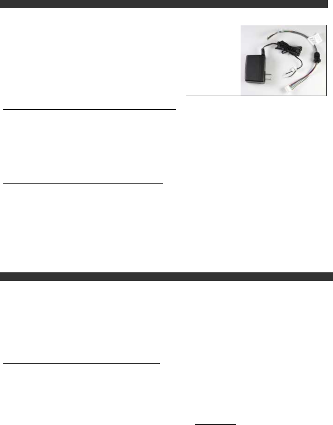
external 8 to 12 VDC power supply can be used, order Ritron model RPS-1B 110 VAC to 12 VDC cube power supply with ferrite
clamp. When using an external supply, the internal D cell Alkaline batteries can be used as back-up. See page 5. The unit will work
with external voltages down to about 6 VDC but the power output will shift to the low power 700mW level when the voltage is too
low.
Low Battery Alert
The callbox will transmit an Alert Tone at the end of each transmission when the batteries approach end-of-life. This allows sufficient
time for you to replace the batteries and assure uninterrupted service. On XD-Series Callboxes the LOW battery alert tone can be
replaced by a LOW battery voice message.
RQX XD-Series Wireless Callbox Installation Instructions
Have questions? Call 800-USA-1-USA (800-872-1872) or visit our website at www.ritron.com 4
A
PPLYING
P
OWER TO THE
XD-S
ERIES
C
ALLBOX
.......................................
The XD-Series Callbox may be powered by:
3 internal D-cell batteries for 700mW operation
An external 8 to 12 VDC source for 2W operation (unit functions as low as 5 VDC with reduced RF power output)
Powering the callbox from internal batteries will allow for an installation that does not require wiring to an external source of power.
Powering the callbox by an external source could, with programming, allow the unit to remain ON, like an intercom*.
To extend battery life, one of two battery saver options may also be used in the analog mode. See “POWER MANAGEMENT OPTIONS”
on page 6. With this mode, Automatic Turn Off must be DISABLED via Field or PC Programming.
Using Internal Batteries
Batteries may be installed in the internal battery holder for a no trenching, no wires required installation. If internal batteries are
used, a LOW battery alert tone or voice message will be transmitted when the battery voltage drops below a programmed value.
The LOW battery tone notifies personnel that the batteries should be replaced. On XD-Series Callboxes the LOW battery alert tone
can be replaced by a LOW battery voice message.
IMPORTANT! When installing D-cell batteries be sure all are the same, and are all new cells. DO NOT mix new and used batteries.
Alkaline D cells are readily available in department stores. Alternatively, low self-discharge (LSD) nickel-metal hydride rechargeable
can be ordered online. The advantage of the LSD NiMH is they can be reused, have a lower internal resistance and sustain good
voltage over the battery life. If operating at very cold temperatures NiMH may be considered. A smart charger will also be needed
with the rechargeable. The XD call box can draw about 0.7 Amp when transmitting so battery health is important.
XD-Series Battery Installation
1. Using the T-25 Torx bit included with the radio, remove the
four corner screws on the plastic interior case and separate
the case halves.
2. Disconnect the power cable connecting the battery holder to
the radio.
3. Install 3 new D-cell batteries into the battery holder. Be sure
to observe polarity as indicated.
4. Re-connect the power cable.
5. Secure the plastic case halves with the corner screws. Be
sure power cable is in the area below the battery holder and
is not pinched between the case halves.
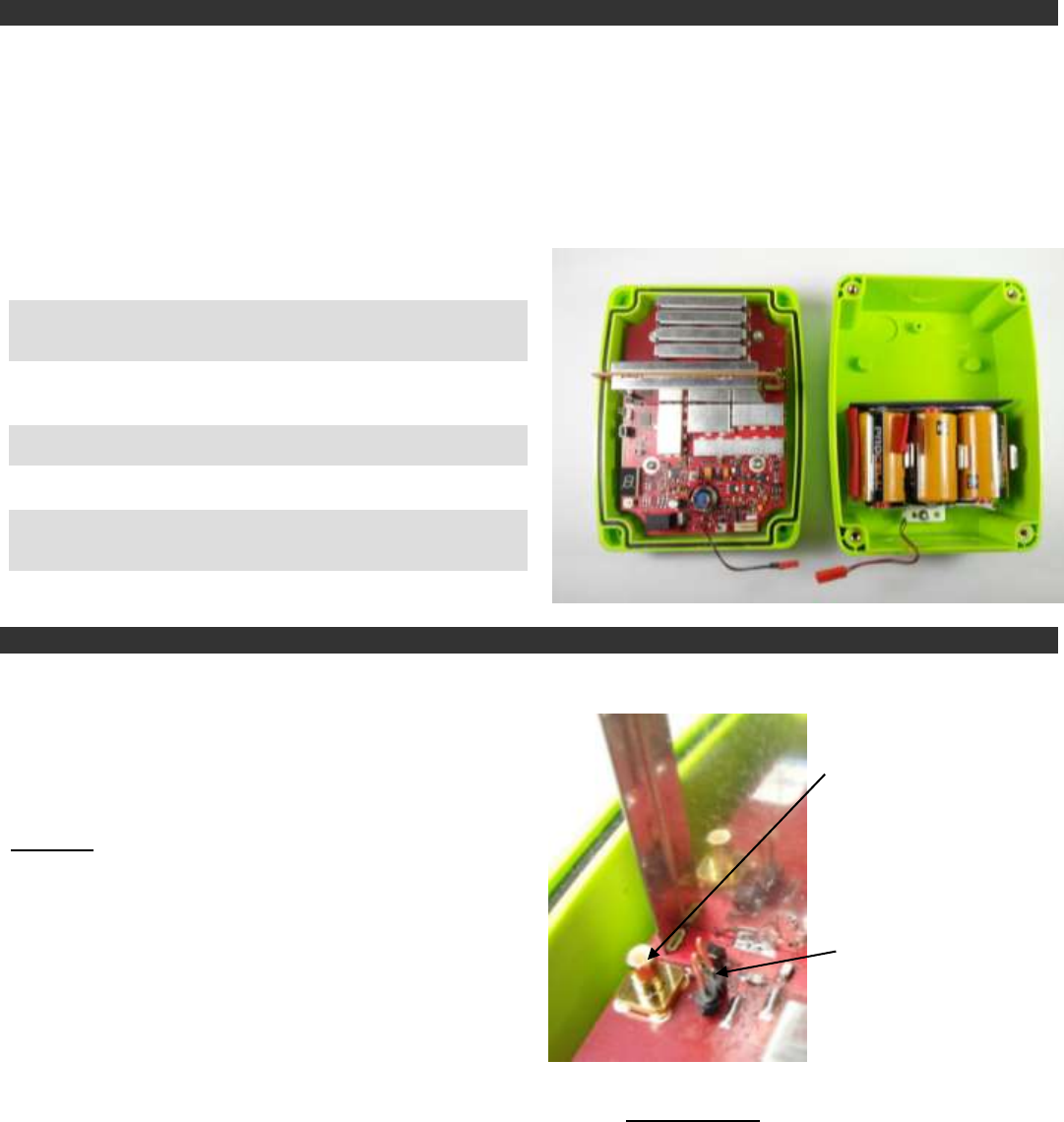
External Antenna Connector and Antenna Jumper Settings
The XD-Series Callbox is equipped with an Antenna Selector
Jumper that will route all incoming and outgoing radio signals
to either the built-in internal antenna, or to the SMB RF Test /
External Antenna connector.
The XD-Series Callbox comes from the factory with the
Antenna Selector Jumper in the “INTERNAL ANTENNA”
position for operation with the built-in internal antenna.
Important - For testing through the SMB RF connector, OR
for connection to an optional external antenna (optional cable
also required), you must remove the Antenna Selector Jumper
PJ201.
For mounting an external antenna the Ritron six inch coaxial
adapter (Ritron # 60201125) can be used to go from the SMB to
a hole in the case. Care must be taken while drilling so as not to
crack the case.
SMB connector
for optional exter-
nal cable and an-
tenna
PJ201 jumped to
connect to inter-
nal antenna
RQX XD-Series Wireless Callbox Installation Instructions
Have questions? Call 800-USA-1-USA (800-872-1872) or visit our website at www.ritron.com 5
Using External +12 VDC Power with Battery Back-up
Note: An additional hole, strain relief, and conduit will need to be installed into the callbox.
The unit may be powered by an external source of 8 to 12 VDC. This
source should be filtered, with minimum noise and hum, and capable of
supplying at least 1 Ampere.
Factory Default programming of the callbox is optimized for battery
power operation. The External 8 to 12 VDC Power Fail Alert option is
NOT ENABLED.
It is recommended that if an external source of power is used, that the
internal batteries be installed as a back-up against loss of power. If this
option is chosen, we recommend that the “External Power Fail Alert”
feature be ENABLED via Field or PC programming.
How the Callbox will operate:
If External 8 to 12 VDC Power Fail Alert Feature is NOT ENABLED:
LOW battery detection can only occur when the external voltage is removed or failed.
Radio will only check for LOW battery or DEAD battery condition when the radio is ON.
If LOW battery is detected, a single tone Alert or voice message will be transmitted at the end of the transmission.
Radio does NOT automatically transmit a LOW battery tone alert or voice message. The callbox must be ON and Alert or voice
message is only sent at the end of a transmission.
If DEAD battery is detected, the radio ceases all operation. A DEAD battery tone is heard on the callbox speaker and the radio
will turn OFF.
If External 8 to 12 VDC Power Fail Alert Feature is ENABLED:
Radio always checks for External voltage when the radio is ON. If loss of external voltage is detected while the radio is in
standby: a single Alert Tone or voice message will be transmitted immediately.
If loss of external voltage is detected while the radio is in receive: a single Alert Tone will be transmitted after the received
message is complete.
If loss of external voltage is detected while the radio is in transmit: a single Alert Tone will be transmitted at the end of the
transmission.
Once loss of external voltage is detected and the Alert Tone is transmitted, the radio will automatically send the Alert Tone once
every hour until external voltage is restored or the batteries are exhausted. If radio is set for Automatic Turn-Off (default setting)
this hourly alert will NOT occur.
If Dead battery is detected the radio ceases all operation, a DEAD battery tone is heard on the callbox speaker and the radio will
turn OFF.
Using External 8 to 12 VDC Power without Battery Back-up
The Ritron RQX callbox can be programmed for always-on operation by disabling the Automatic Turn-Off option. This is
accomplished using the RQX PC Programmer, or through Field Programming. Once Automatic Turn-Off is disabled, the user
simply turns on the RQX by pressing the front panel PTT button and it will remain on as long as power is applied. If power to the
callbox is lost then restored, the user must press the front panel PTT to restart the radio. For externally powered callboxes, battery
backup is one method of keeping the radio on if the primary external power is lost.
For users that do not want to “restart” the callbox after a power loss, the callbox can be modified to automatically restart
after a power loss. By loading 15 k ohm in R628 the external power supply will automatically turn on if there is an input. Also
PJ602 must be in the “sensor turn-on” mode with the sensor input (pin 2 of PJ601) tied to ground. This configuration will also turn
the internal battery on if the external power fails. R628 need not be loaded if only internal batteries are used.
For details or questions about this modification contact Ritron at 1-800-872-1872
Important considerations before applying this modification:
The Automatic Turn-Off option must be disabled.
When Automatic Turn-Off is disabled the unit will consume the largest amount of current, but is always ready to instantly receive
messages. This mode should only be considered if an external source of power is available. If internal batteries only are used, the
radio would work only a few days.
The callbox receiver will always be on. All radio communication on the programmed frequency and tone will be heard over the
RQX callbox.
For External
+12VDC power,
order Ritron model
RPS-EXPO 110
VAC to 12 VDC
cube supply.
RQX XD-Series Wireless Callbox Installation Instructions
Have questions? Call 800-USA-1-USA (800-872-1872) or visit our website at www.ritron.com 6
P
OWER
M
ANAGEMENT
O
PTIONS
...........................................................
Automatic Turn-Off ............................................................................................................................... (Field or PC Programmable)
In this mode, the callbox will automatically turn itself off after a programmed period of no activity (no transmissions made and no
calls received) has elapsed. Once the unit has turned itself off, it can only be turned back on by depressing the ON/PTT Button.
The programmed period of no activity necessary before the unit turns itself off is called the RQX Reset Time. RQX Reset Time and
Automatic Turn-Off can both be Field programmed, or PC programmed by the factory or your Ritron dealer via the Ritron RQX
Series PC Programmer. Automatic Turn-Off mode is the factory default mode for power management with an RQX Reset Time of
10 seconds.
Analog Radio Battery Saver .....................................................................................................................(PC Programmable Only)
This mode, only available for the analog radio, is similar to the Automatic Turn-Off mode except that the unit does NOT turn itself off
after the RQX Reset Time has elapsed. Instead it reverts to a mode where the unit goes to sleep and periodically wakes up to test
for receive activity on the channel. The Sleep Period (called Battery Saver Sleep Time) can be set using the Ritron RQX Series PC
Programmer to between 0.5 and 8 seconds. Longer sleep times result in better battery life, but increase the chances that activity on
the channel may be missed. The unit will come out of this mode when activity is detected during the wake-up period or if the
ON/PTT button is pressed. The Automatic Turn-Off and Battery Saver modes cannot be used together.
Neither “Automatic Turn-Off” nor “Battery Saver” Used .................................................................. (Field or PC Programmable)
If neither Automatic Turn-Off nor Battery Saver are used the unit will consume the largest amount of current, about 90 mA, but is
always ready to instantly receive messages. This mode should only be considered if an external source of power is available (see
“Using External 8 to 12 VDC Power with Battery Back-up” on page 5).
NXDN Radio Power Consumption ……………………………………………………………………………… (Automatic)
“ON with sync”: When the NXDN radio is actively looking for a sync word in receive mode it consumes about 80 mA. The digital
receiver IC is looking for the NXDN preamble and sync word and once found will wake up the NXDN processing board. Once awake
while decoding voice the radio draws about 270 mA with a low audio volume setting. When the received signal disappears the unit’s
consumption goes back to about 80 mA.
“Always ON”: NXDN board is always ON consuming about 250 mA in RX mode.
If Automatic Turn-Off is enable the current will drop to zero at the expiration of the reset timer. If Automatic Turn-Off is not enabled
the unit will continue drawing 80 mA in “ON with sync” or 250 mA in ”Always ON” mode.
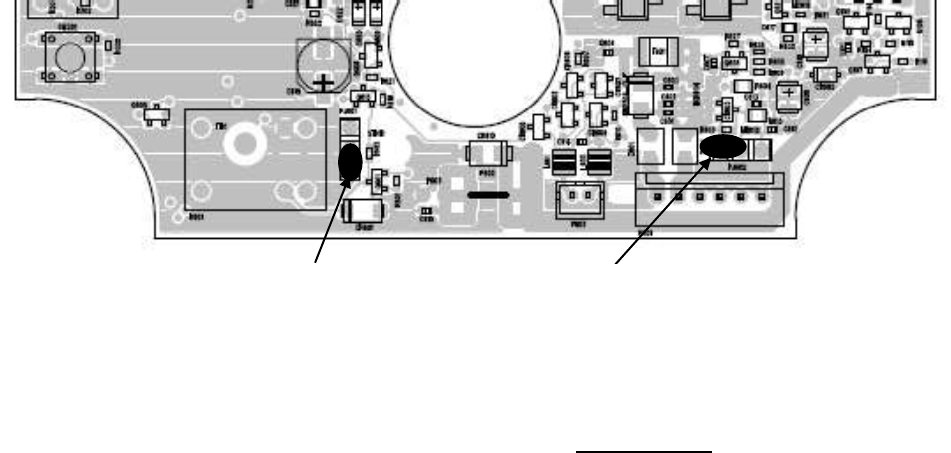
Sensor Turn-On ...................................................................................................................................................................................
When operating a XD-Series Callbox with Automatic Turn-Off enabled, the unit can be configured to turn itself ON any time the
Sensor Input is pulled LOW (ground). This allows an external switch closure to activate the Callbox. When the switch closure is
detected the Callbox will turn on and automatically transmit the Sensor On alert or Sensor ON voice message. The Callbox is then
in normal operating mode and will automatically turn itself off after a programmed period of no activity as described in the Automatic
Turn-Off topic in this section. For Sensor Turn-On operation the Sensor Turn-On jumper must be placed into the “Turn-On” position.
Refer to FIG-1 below for correct placement of the jumper. If the Sensor Input is not used the jumper placement has no effect on
Callbox operation.
Relay Normally
open
6 5 4 3 2 1
Sensor turn ON
RQX XD-Series Wireless Callbox Installation Instructions
Have questions? Call 800-USA-1-USA (800-872-1872) or visit our website at www.ritron.com 7
C
ALLBOX
C
ONTROLS AND
C
ONNECTORS
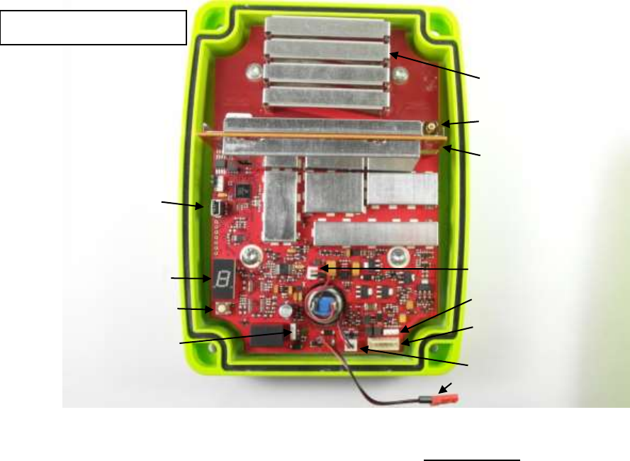
...............................................
SMB RF Connector
SMB style RF connector for external antennas. The antenna
jumper must be in the “SMB” position when using the SMB RF
connector.
Internal Antenna
An internal antenna is etched and/or secured to the PCB. When
used, the antenna jumper must be in the “ANTENNA” position.
Antenna Jumper
The antenna jumper connects either the internal antenna or the
SMB RF connector.
Sensor Turn-On Jumper
The Sensor Turn-On jumper can be set to turn-on the radio
whenever the Sensor Input is pulled low. (See FIG-1)
Relay Polarity Jumper
The Relay Polarity jumper can set the relay output to normally
open or normally closed. (See FIG-1)
Case Screws
A T-25 Torx screw is located in each corner of the case front.
These 4 screws are used to secure the case front containing
the radio, to the case back that contains the batteries.
Input/Output Connector
The 6-pin, polarized connector is used to connect external
input/output devices. This allows connection of an external 8 to
12 VDC input, an external DC level sensor input, and a 3A
contact switch closure output.
Microphone
The microphone is installed on the PCB back side.
Speaker Connector
The internal speaker is connected to the radio printed circuit
board with a polarized connector.
On/PTT Connector
The On/PTT switch is connected to the radio printed circuit
board with a polarized connector.
USB Programming Connector
A Mini-USB style connector is used to connect the cable from
the PC programmer to the radio.
Program Button
A small, momentary pushbutton is used for field programming
the XD-Series Callbox.
Program Display
A single digit LED display is used during field programming of
the radio.
Battery Holder
The battery holder inside the case back is used for the
installation of D-cell alkaline batteries. Refer to the labels
beneath the cells for correct installation of the batteries.
Battery Mating Connectors
Polarized, 2-pin mating connectors are used to connect the
batteries to the radio circuit board.
SMB RF port
Internal antenna
USB programming
I/O connector
Program display
Program button
ON/PTT connector
Speaker connector
Relay NC/NO jumper
Sensor Turn ON/Normal
NXDN board
Battery mating connector
Fig 2 Features
RQX XD-Series Wireless Callbox Installation Instructions
Have questions? Call 800-USA-1-USA (800-872-1872) or visit our website at www.ritron.com 8
XD-S
ERIES
C
ALLBOX
I
NSTALLATION
I
NSTRUCTIONS
..................................
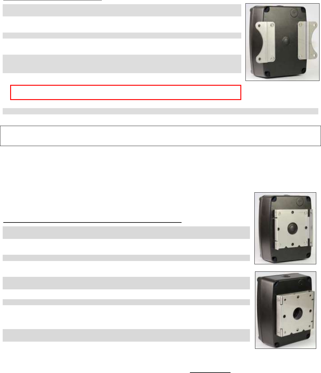
The XD-Series Callbox can be mounted to virtually any surface using the mounting brackets included with the product. Choose a
type of screw thread and screw length which will hold firmly in the surface to which the unit will be mounted.
MOUNTING THE XD-SERIES CALLBOX
1. Loosen the (4) screws in the front corners of the case and separate the case front from the
case back.
2. Install new D-cell alkaline batteries into the battery holder. Refer to FIG-2, or the labels
beneath the cells, for correct installation of the batteries.
3. If required, program the radio. Refer to the programming section of this manual for details.
4. Disconnect the battery mating connectors. Set the case front containing the radio circuit board
aside.
5. Install the mounting brackets included with the product to the XD-Series Callbox case back.
The recommended installation is with the brackets on each side as shown, installing the
brackets top and bottom may reduce radio range.
6. Position the case in the chosen installation location and secure it in place with four screws.
CAUTION
Do not drill or penetrate the XD-Series Callbox case with any additional
holes. Use only the mounting brackets included with the product.
7. Reconnect the battery mating connectors between the case front and case back.
8. Fasten the case front to the case back with the four (4) corner screws.
COVERAGE Depending on the unit location and installation, the XD-Series Callbox can cover up to 1 mile line of sight. To in-
crease range, use an external antenna that is mounted higher. Contact RITRON for a RAM-1545 Magnet Mounted
Antenna.
O
PTIONAL
XD-S
ERIES
C
ALLBOX
P
EDESTAL
M
OUNTING
B
RACKET
I
NSTALLATION
I
NSTRUCTIONS
.................................................................
The XD-Series Callbox can be mounted to a gooseneck pedestal or a post using the optional RQX-XD-
GN mounting bracket. The RQX-XD-GN includes hardware necessary to attach the bracket to the
Callbox, but does not include hardware for attaching to a gooseneck pedestal or a post.
MOUNTING THE XD-SERIES CALLBOX TO A GOOSENECK PEDESTAL
1. Loosen the (4) screws in the front corners of the case and separate the case front from the case
back.
2. Install new D-cell alkaline batteries into the battery holder. Refer to FIG-2, or the labels beneath
the cells, for correct installation of the batteries.
3. If required, program the radio. Refer to the programming section of this manual for details.
4. Disconnect the battery mating connectors. Set the case front containing the radio circuit board
aside.
5. Install one half of the optional RQX-Q-GN mounting bracket to the XD-Series Callbox case back as
shown at top right.
6. Reconnect the battery mating connectors between the case front and case back.
7. Fasten the case front to the case back with the four (4) corner screws.
8. Install the other half of the optional RQX-Q-GN mounting bracket to a gooseneck pedestal or a
post with the folded sides of the bracket to the sides. The hardware necessary to attach to a
gooseneck pedestal or a post is not included with the RQX-Q-GN.
9. Mate the mounting bracket on the XD-Series Callbox to the bracket on the gooseneck pedestal or
a post as shown at bottom right and secure with the 4 screws included with the RQX-Q-GN.
!
RQX XD-Series Wireless Callbox Installation Instructions
Have questions? Call 800-USA-1-USA (800-872-1872) or visit our website at www.ritron.com 9
O
PTIONAL
Q-S
ERIES
E
XTERNAL
A
NTENNA
I
NSTALLATION
I
NSTRUCTIONS
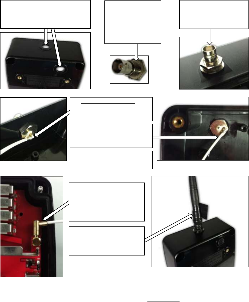
.......
Order Ritron PN 60201125 (Cable Assembly, RF SMB-BNC, Q-Series)
4a. BNC installed in the case top
Position the connector so that the cable
is routed as shown, downward toward
the inside of the case back.
4b. BNC installed in the case back
Position the connector so that the cable
is routed as shown, downward toward
the bottom of the case.
4c. Once positioned, tighten the ½” nut
while holding the BNC connector in
place with a ½” open end wrench.
1. The antenna connector can be installed
in one of the two locations shown, on the
case top or case back. Using the center
pilot hole at the desired location, drill a 1/2
inch hole for the BNC antenna connector.
3. From the inside of the case
insert the BNC connector
through the hole and secure
with the flat washer, lockwasher
and 1/2” nut.
2. Before installing the
BNC connector into the
case, place the sealing
washer on the connector
as shown. Be sure it is
completely seated in the
recessed area and is flat,
with no twist or binding.
5. Once the BNC antenna connect-
or is installed on the case, plug the
SMB RF connector into the mating
connector on the RQX PCB and
place the antenna jumper into the
ANT position as shown (See page 6
for additional details)
6. With the external antenna con-
nected to the BNC connector, tightly
wrap the entire connection with the
black silicon tape included in the
60201125 antenna connector kit.
RQX XD-Series Wireless Callbox Field Programming
Have questions? Call 800-USA-1-USA (800-872-1872) or visit our website at www.ritron.com 10
XD-S
ERIES
F
IELD
P
ROGRAMMING
O
VERVIEW
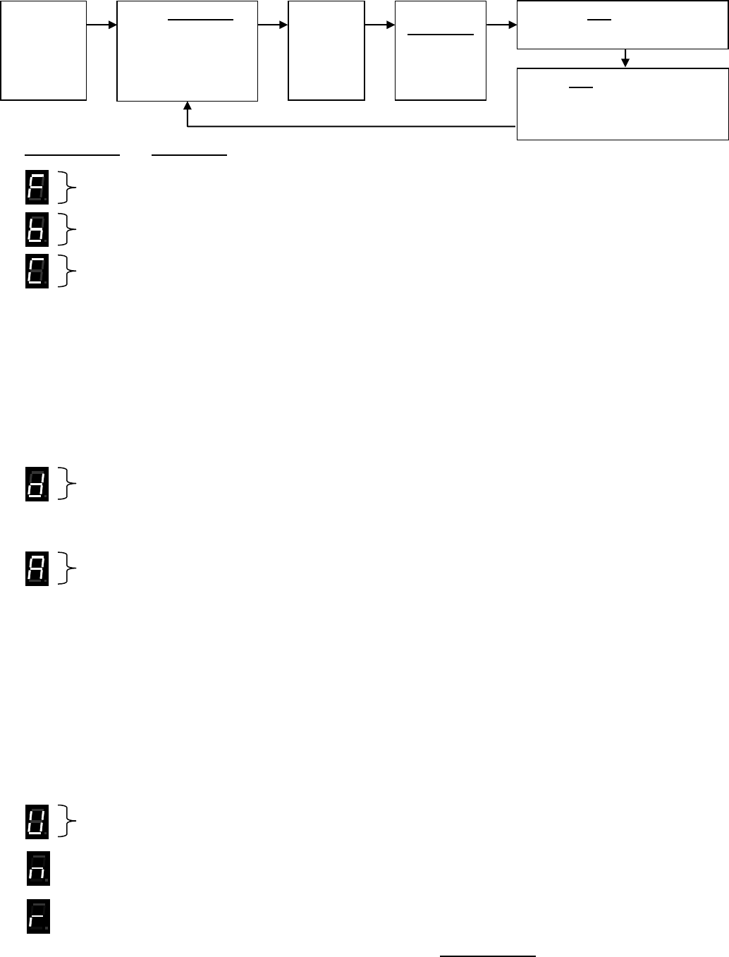
..........................................
Program Codes Table Codes
Enter a 2-digit or 3-digit Frequency code from Table 1.
Enter a 2-digit Quiet Call code from Table 2 or a 3-digit Digital Quiet Call code from Table 3.
For Paging, GateGuard® and Listen In Decode: (for NXDN see “r” program code)
Enter a 2-digit, 2-Tone Paging code from Table 4 or
Enter 1 plus any 3–7 digit DTMF Code or
Enter 2 plus any 3–7 digit Selcall Code
Enter 3 plus any 2-digit, 2-Tone Paging code from Table 4 for Secondary or
Enter 31 plus any 3–7 digit DTMF Code for Secondary or
Enter 32 plus any 3–7 digit Selcall Code for Secondary
Enter a 3-digit Operation Code
Enter 3-digit Features Codes
For Encode ANI: (for NXDN see “r” program code)
Enter a 1 plus any 3–7 digit DTMF Code or
Enter a 2 plus any 3–7 digit Selcall Code
Enter any 2-digit or 3-digit RQX Feature code from Table 5 to:
Enable or disable Companding.
Enable or disable Call Tone.
Enable or disable external power loss alert.
Enable or disable Automatic Turn-Off.
Enable or disable Busy Channel TX Inhibit.
Set microphone gain fixed or AGC.
Set RQX Reset Time.
Set switch output operation.
Reset RQX to Factory default programming.
Record and Playback Voice Messages.
Set to analog or NXDN digital modes
Enter the desired Speaker Volume Level as a 2–digit number from 20 – 99.
Enter 1 to 7 for the desired NXDN function then the 1 to 5 digit ID code (see table 8)
Enter 1 to 7 to read out the desired NXDN 1 to 5 digit code (see table 8)
Place the
XD-Series
Callbox
into
Program
mode.
Use PROGRAM
button to scroll to
one of the following
Program Code
characters:
F b C d A U n r
Pause, a
hyphen
will
appear
on the
display.
Using the
PROGRAM
button,
enter the
desired
Table Code.
Press PTT button to save
programming entry.
Press PTT button a second time
to Exit programming.
or
Proceed with next program entry.
RQX XD-Series Wireless Callbox Field Programming
Have questions? Call 800-USA-1-USA (800-872-1872) or visit our website at www.ritron.com 11
H
OW TO
F
IELD
P
ROGRAM
F
REQUENCY
&
T
ONE
C
ODES
............................
To match other radios, the owner can select Frequency, Tone and DQC Codes from Table 1, Table 2 and Table 3 on pages 11 and
13. In our example, we will program an RQX-417NX to operate on the "Brown Dot" frequency of 464.500 MHz with 100.0 Hz tone.
NOTES:
1. Refer to Table 1 on page 11 to determine the two-digit frequency code and write it down.
2. Refer to Table 2 on page 12 to determine the two-digit tone code for 100.0 Hz and write it down.
3. Loosen the (4) screws in the front corners of the case.
4. Separate the case front from the case back, leaving the batteries connected to the radio. Make sure the
unit has batteries installed.
NOTE: The voltage of the batteries must be greater than 3.3 VDC to program properly.
5. Press and release the ON/PTT button on the front of the unit to turn the radio on.
6. Press and HOLD the Program Button (See FIG-2 on page 7 for location). A "P" will appear on the program
display as you enter program mode and the radio will beep rapidly.
7. Release the program button after the beeping has stopped. The radio will emit a triple beep indicating that
the radio is in program mode and a hyphen will appear on the program display.
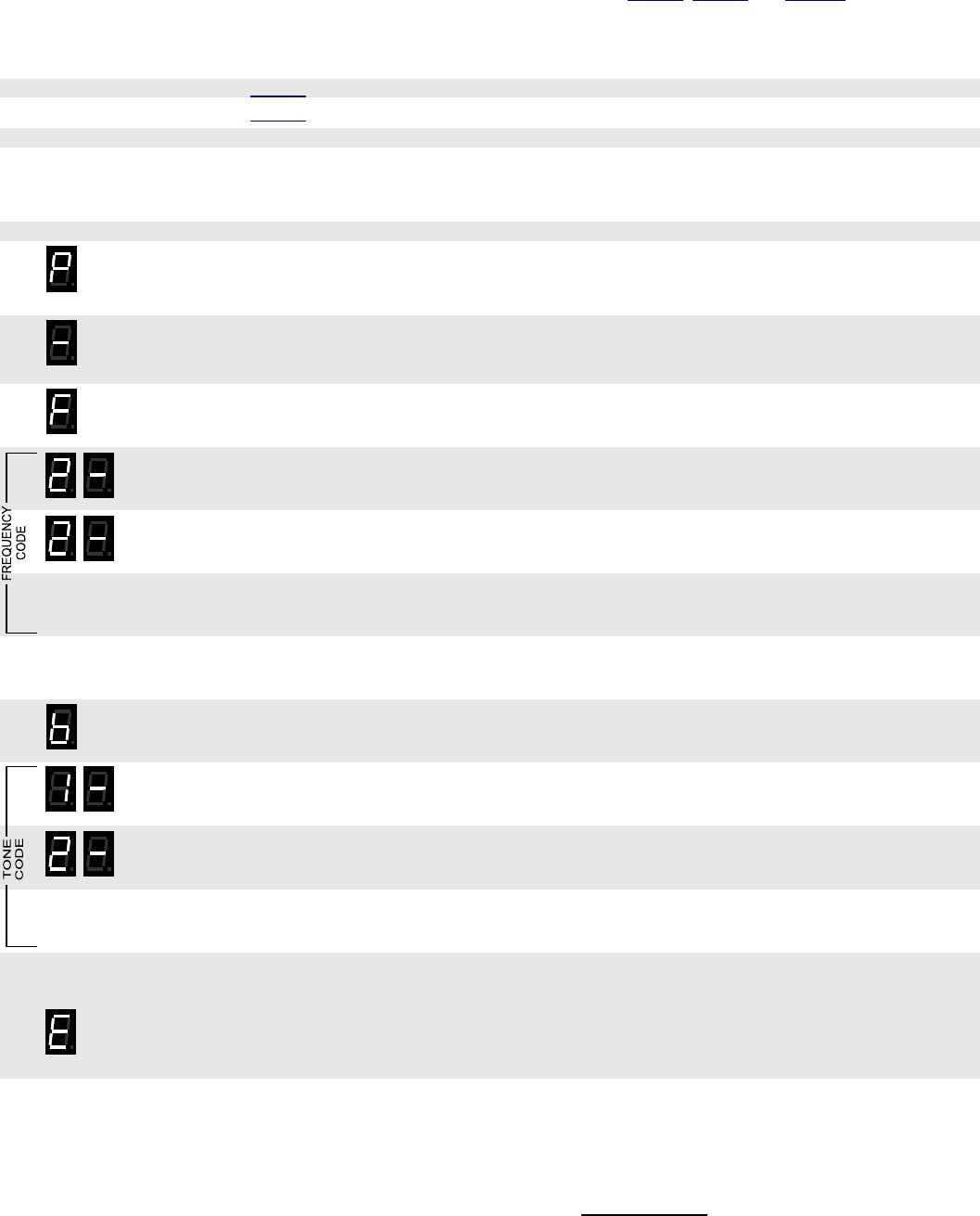
8. Click the Program button until the program display shows the Program Code “F”. Pause—the radio will
sound a low tone and show a hyphen across the center of the display to indicate that it is ready to accept
the 2 or 3-digit Frequency code from Table 1.
9. Enter the 1st digit of the frequency code by clicking the Program button until the program display shows the
desired number. Pause—the radio will sound a low tone and show a hyphen across the center of the
display to indicate that it is ready to accept the next digit.
10. Enter the 2nd digit of the frequency code by clicking the Program button until the program display shows the
desired number. Pause—the radio sounds a low tone and will show a hyphen across the center of the
display to indicate that it is ready to accept the next digit.
11. If necessary, enter the 3rd digit of the frequency code by clicking the Program button until the program
display shows the desired number. Pause—the radio sounds a low tone and will show a hyphen across the
center of the display to indicate that it is ready to accept the next digit
12. Press and release the ON/PTT button to save your programming. A triple beep will sound to indicate that
programming was successful and a hyphen will appear on the program display. The radio is now ready for
another program entry.
13. Click the Program button until the program display shows the Program Code “b”. Pause—the radio will
sound a low tone and show a hyphen across the center of the display to indicate that it is ready to accept
the 2-digit Quiet-Call code or 3-digit Digital Quiet-Call code from Table 2 or Table 3.
14. Enter the 1st digit of the tone code (or 1st digit of the DQC code) by clicking the Program button until the
program display shows the desired number. Pause—the radio sounds a low tone and will show a hyphen
across the center of the display to indicate that it is ready to accept the next digit.
15. Enter the 2nd digit of the tone code (or 2nd digit of the DQC code) by clicking the Program button until the
program display shows the desired number. Pause—the radio sounds a low tone and will show a hyphen
across the center of the display to indicate that it is ready to accept the next digit.
16. FOR DQC CODES ONLY – Enter the 3rd digit of the DQC code by clicking the Program button until the
program display shows the desired number. Pause—the radio sounds a low tone and will show a hyphen
across the center of the display to indicate that it is ready to accept the next digit.
17. Press and release the ON/PTT button to save your programming. A triple beep will sound to indicate that
programming was successful and a hyphen will appear on the program display. The radio is now ready for
another program entry.
NOTE: An error tone will sound if you attempt to save an incorrect code, an "E" will appear on the display.
Check the digits you are attempting to enter, then re-enter. This will also occur if the radio frequency has
been PC programmed to something other than one of the table codes from Table1.
18. Once you have made your final program entry, press the ON/PTT button a final time to turn the radio off.
Turn the radio back on for normal operation.
22
12
RQX XD-Series Wireless Callbox Field Programming
Have questions? Call 800-USA-1-USA (800-872-1872) or visit our website at www.ritron.com 12
T
ABLE
1:
P
ROGRAMMABLE
F
REQUENCY
C
ODES
........................................
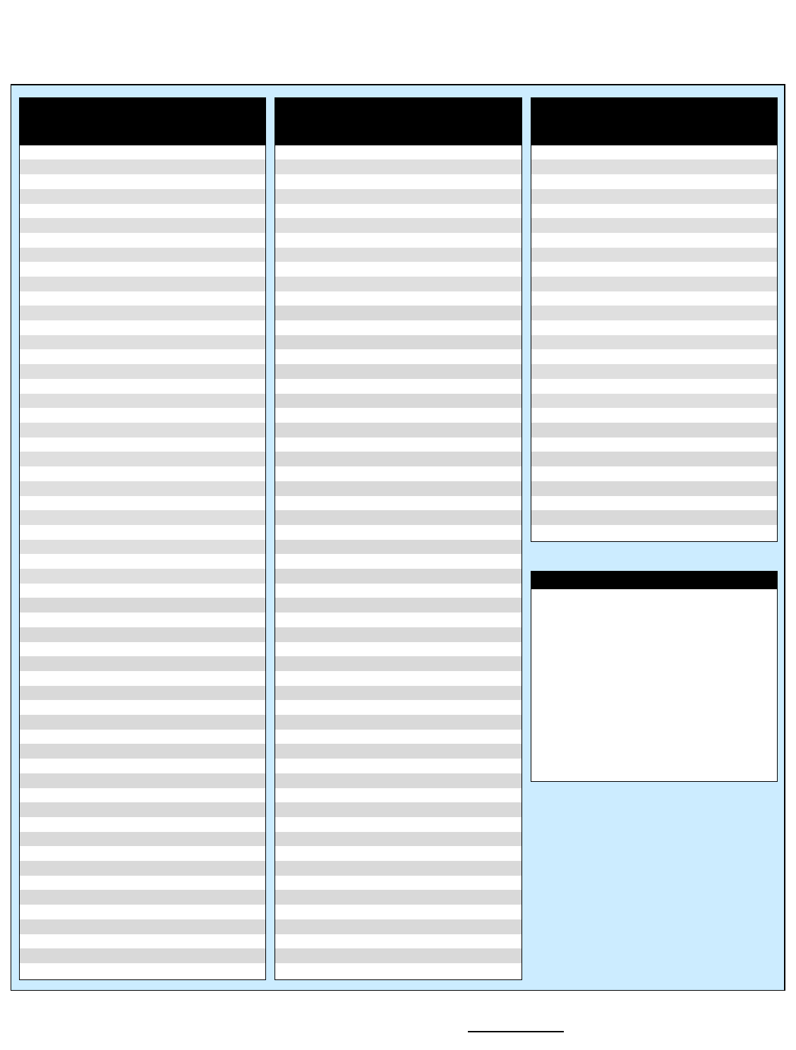
UHF Business Band Models
Code Frequency Color Dot BW
09 469.2625 12.5 †
10 462.5750 White Dot 12.5 †
11 462.6250 Black Dot 12.5 †
12 462.6750 Orange Dot 12.5 †
13 464.3250 12.5 †
14 464.8250 12.5 †
15 469.5000 12.5 †
16 469.5500 12.5 †
17 463.2625 12.5 †
18 464.9125 12.5 †
19 464.6000 12.5 †
20 464.7000 12.5 †
21 462.7250 12.5 †
22 464.5000 Brown Dot 12.5
23 464.5500 Yellow Dot 12.5
24 467.7625 J 12.5
25 467.8125 K 12.5
26 467.8500 Silver Star 12.5
27 467.8750 Gold Star 12.5
28 467.9000 Red Star 12.5
29 467.9250 Blue Star 12.5
30 461.0375 12.5
31 461.0625 12.5
32 461.0875 12.5
33 461.1125 12.5
34 461.1375 12.5
35 461.1625 12.5
36 461.1875 12.5
37 461.2125 12.5
38 461.2375 12.5
39 461.2625 12.5
40 461.2875 12.5
41 461.3125 12.5
42 461.3375 12.5
43 461.3625 12.5
44 462.7625 12.5
45 462.7875 12.5
46 462.8125 12.5
47 462.8375 12.5
48 462.8625 12.5
49 462.8875 12.5
50 462.9125 12.5
51 464.4875 12.5
52 464.5125 12.5
53 464.5375 12.5
54 464.5625 12.5
55 466.0375 12.5
56 466.0625 12.5
57 466.0875 12.5
58 466.1125 12.5
59 466.1375 12.5
60 466.1625 12.5
61 466.1875 12.5
62 466.2125 12.5
63 466.2375 12.5
64 466.2625 12.5
65 466.2875 12.5
UHF Business Band Models
Code Frequency Color Dot BW
66 466.3125 12.5
67 466.3375 12.5
68 466.3625 12.5
69 467.7875 12.5
70 467.8375 12.5
71 467.8625 12.5
72 467.8875 12.5
73 467.9125 12.5
74 469.4875 12.5
75 469.5125 12.5
76 469.5375 12.5
77 469.5625 12.5
78 462.1875 12.5
79 462.4625 12.5
80 462.4875 12.5
81 462.5125 12.5
82 467.1875 12.5
83 467.4625 12.5
84 467.4875 12.5
85 467.5125 12.5
86 451.1875 12.5
87 451.2375 12.5
88 451.2875 12.5
89 451.3375 12.5
90 451.4375 12.5
91 451.5375 12.5
92 451.6375 12.5
93 452.3125 12.5
94 452.5375 12.5
95 452.4125 12.5
96 452.5125 12.5
97 452.7625 12.5
98 452.8625 12.5
99 456.1875 12.5
100 456.2375 12.5
101 456.2875 12.5
102 468.2125 12.5
103 468.2625 12.5
104 468.3125 12.5
105 468.3625 12.5
106 468.4125 12.5
107 468.4625 12.5
108 468.5125 12.5
109 468.5625 12.5
110 468.6125 12.5
111 468.6625 12.5
112 456.3375 12.5
113 456.4375 12.5
114 456.5375 12.5
115 456.6375 12.5
116 457.3125 12.5
117 457.4125 12.5
118 457.5125 12.5
119 457.7625 12.5
120 457.8625 12.5
121 461.3175 12.5
122 464.8375 12.5
VHF Business Band Models
Code Frequency Color Dot BW
03 151.6250 Red Dot 12.5 †
04 151.9550 Purple Dot 12.5 †
05 151.9250 12.5 †
06 154.5400 12.5 †
07 154.5150 12.5 †
08 154.6550 12.5 †
09 151.6850 12.5 †
10 151.7150 12.5 †
11 151.7750 12.5 †
12 151.8050 12.5 †
13 151.8350 12.5 †
14 151.8950 12.5 †
15 154.4900 12.5 †
16 151.6550 12.5 †
17 151.7450 12.5 †
18 151.8650 12.5 †
24 151.7000 12.5
25 151.7600 12.5
26 152.7000 12.5 †
27 152.8850 12.5
28 152.9150 12.5
29 152.9450 12.5
30 151.5125 12.5
31 154.5275 12.5
32 153.0050 12.5
33 158.4000 12.5
34 158.4075 12.5
Notes
† Frequency code was 25 KHz
bandwidth prior to the 2013 FCC
Narrowband Mandate.
BW is the bandwidth in kHz.
12.5 kHz indicates a narrow band
channel, 25 kHz indicates a wide band
channel.
If the callbox has been PC pro-
grammed to a non-table frequencies it
cannot be changed via field program-
ming. Code 999 will appear when read
out.
RQX XD-Series Wireless Callbox Field Programming
Have questions? Call 800-USA-1-USA (800-872-1872) or visit our website at www.ritron.com 13
C
ANADIAN
F
REQUENCY
C
ODES
............................................................
Canada Models
UHF Business Band
Code Frequency Color Dot BW
01 458.6625 25
02 469.2625 25
Canada Models
VHF Business Band
Code Frequency Color Dot BW
01 151.055 25
02 151.115 25
T
ABLE
2:
P
ROGRAMMABLE
QC
T
ONE
C
ODES
..........................................
Code Frequency
01 67.0
02 71.9
03 74.4
04 77.0
05 79.7
06 82.5
07 85.4
08 88.5
09 91.5
10 94.8
11 97.4
12 100.0
13 103.5
Code Frequency
14 107.2
15 110.9
16 114.8
17 118.8
18 123.0
19 127.3
20 131.8
21 136.5
22 141.3
23 146.2
24 151.4
25 156.7
26 162.2
Code Frequency
27 167.9
28 173.8
29 179.9
30 186.2
31 192.8
32 203.5
33 210.7
34 218.1
35 225.7
36 233.6
37 241.8
38 250.3
39 69.4
Code Frequency
40 159.8
41 165.5
42 171.3
43 177.3
44 No Tone
45 183.5
46 189.9
47 196.6
48 199.5
49 206.5
50 229.1
51 254.1
00 No Tone
T
ABLE
3:
P
ROGRAMMABLE
D
IGITAL
DQC
T
ONE
C
ODES
............................
Code
023
025
026
031
032
036
043
047
051
053
054
065
071
Code
072
073
074
114
115
116
122
125
131
132
134
143
145
Code
152
155
156
162
165
172
174
205
212
223
225
226
243
Code
244
245
246
251
252
255
261
263
265
266
271
274
306
Code
311
315
325
331
332
343
346
351
356
364
365
371
411
Code
412
413
423
431
432
445
446
452
454
455
462
464
465
Code
466
503
506
516
523
532
546
565
606
662
612
624
627
Code
631
632
645
654
664
703
712
723
731
732
734
743
754
RQX XD-Series Wireless Callbox Field Programming
Have questions? Call 800-USA-1-USA (800-872-1872) or visit our website at www.ritron.com 14
H
OW TO
F
IELD
P
ROGRAM
2-T
ONE
,
DTMF
OR
S
ELCALL
D
ECODE
(R
ECEIVE
)
O
PERATION
........................................................................................
For special applications, it is desirable to program the XD-Series Callbox for 2-Tone, DTMF or Selcall decode (receive) operation.
The user is able to field program the radio for one of the 9 pre-determined tone pairs specified in Table 4 on page 15, or for any 3-7
digit DTMF or Selcall sequence. The 2-Tone codes correspond to field programmable 2-Tone encode (transmit) codes available in
other RITRON portable and base radios.
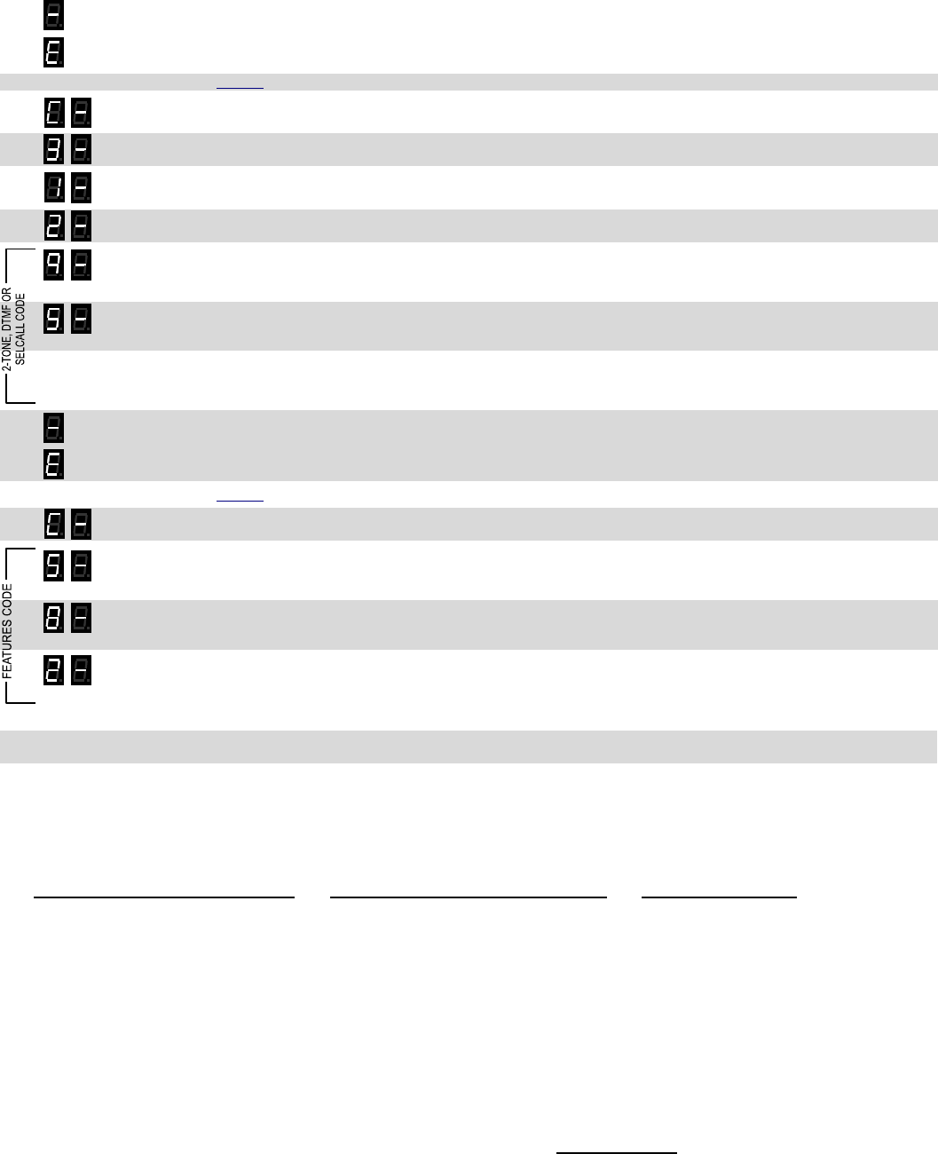
Programming the radio for 2-Tone, DTMF or Selcall decode operation MUST BE DONE IN THE FOLLOWING ORDER!
1. Program the desired Operation code (Refer to Table 4). This will delete any previous Primary or Secondary Decode code
programming.
2. Program the desired 2-Tone, DTMF or Selcall Primary Decode code (Refer to Table 4). An “E” error indication will appear
on the display if the programmed Operation code does not require a Primary Decode code.
3. If required, program the desired 2-Tone, DTMF or Selcall Secondary Decode code (Refer to Table 4). An “E” error
indication will appear on the display if the programmed Operation code does not require a Secondary Decode code.
The Secondary Decode code must be the same type as the Primary Decode code. For example, if the Primary
Decode code was set for DTMF, the Secondary Decode code must also be DTMF.
The Secondary Decode code cannot be the same as the Primary Decode code.
If using DTMF or Selcall, the Primary and Secondary Decode codes must have the same number of digits.
4. Program the desired Features code (Refer to Table 4).
In the following example we will program an RQX-417NX for paging operation with 2-Tone Decode Code 94 frequencies of 389.0
and 669.9 Hz, and for Listen In operation with 2-Tone Decode Code 95 frequencies of 410.8 and 707.3 Hz. The Listen In time will
be set for 10 seconds.
1. Loosen the (4) captive screws in the front corners of the case and separate the case front from the case back, leaving the
batteries connected to the radio. Make sure the unit has batteries installed. The voltage of the batteries must be greater
than 3.3 VDC to program properly.
2. Press and release the ON/PTT button on the front of the unit to turn the radio on.
3. Press and HOLD the Program Button (See FIG-2 on page 7 for location). A "P" will appear on the program display as you
enter program mode and the radio will beep rapidly. Release the program button after the beeping has stopped. The radio
will emit a triple beep indicating that the radio is in program mode and a hyphen will appear on the program display.
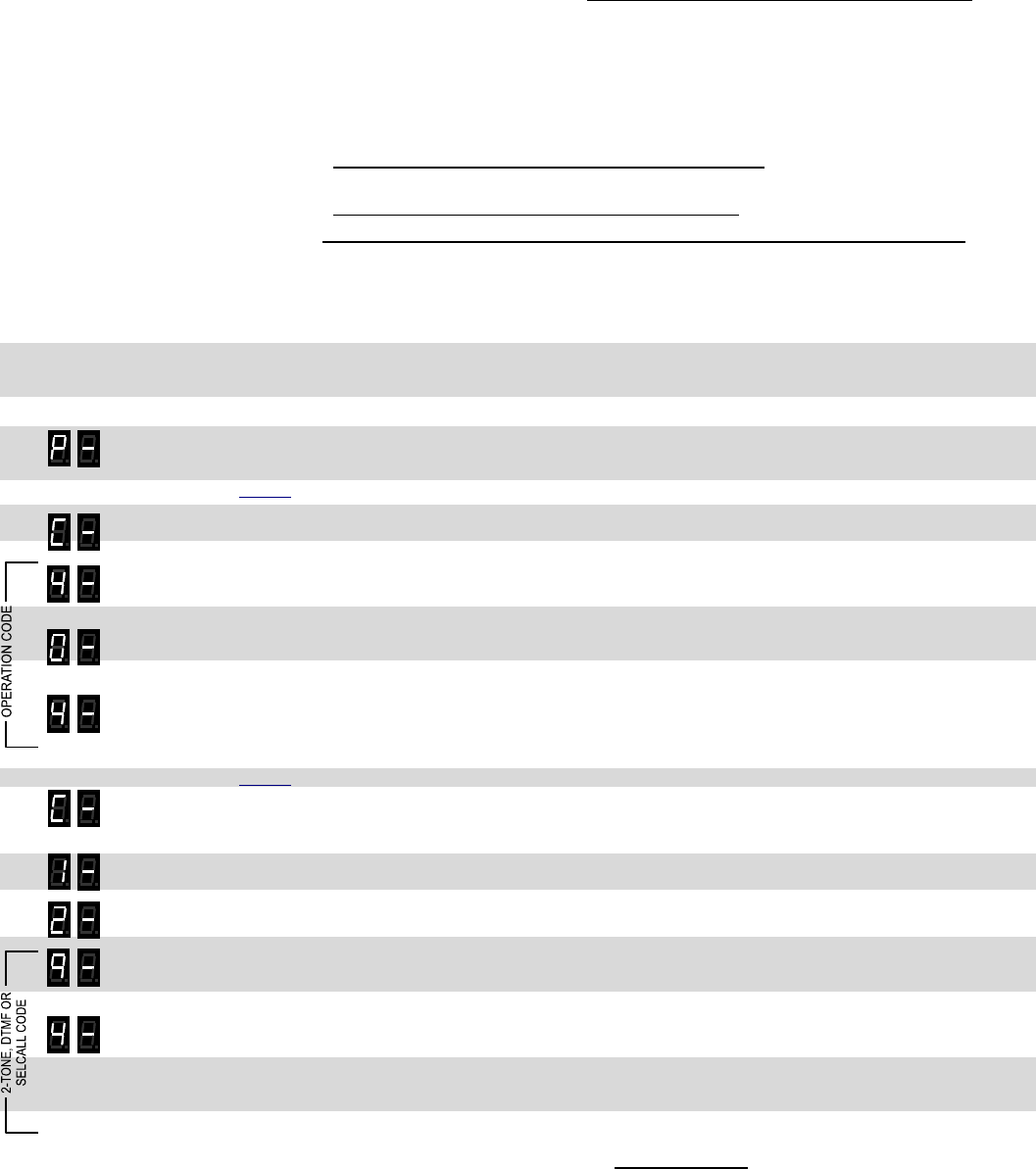
404 4. Refer to Table 4 on page 15 to determine the three-digit Operation code for Paging and Listen In operation.
5. Click the Program button until the program display shows the Program Code “C”. Pause—the radio will sound a low tone
and show a hyphen across the center of the display to indicate that it is ready to accept the next programming code.
6. Enter the 1st digit of the Operation Code by clicking the Program button until the program display shows the desired
number. Pause—the radio will sound a low tone and show a hyphen across the center of the display to indicate that it is
ready to accept the next digit.
7. Enter the 2nd digit of the Operation Code by clicking the Program button until the program display shows the desired
number. Pause—the radio sounds a low tone and will show a hyphen across the center of the display to indicate that it is
ready to accept the next digit.
8. Enter the 3rd digit of the Operation Code by clicking the Program button until the program display shows the desired
number. Pause—the radio sounds a low tone and will show a hyphen across the center of the display to indicate that it is
ready to accept the next digit.
9. Press and release the ON/PTT button to save your programming. A triple beep will sound to indicate that programming
was successful and a hyphen will appear on the program display. The radio is now ready for another program entry.
94 10. Refer to Table 4 on page 15 to determine the two-digit code for 2-tone decode on 389.0 and 669.9 Hz.
11. Click the Program button until the program display shows the Program Code “C”. Pause—the radio will sound a low tone
and show a hyphen across the center of the display to indicate that it is ready to accept a 2-digit 2-Tone code from Table 4,
or a 3 to 7-digit DTMF or Selcall decode sequence.
12. FOR DTMF CODES ONLY – Enter a “1” using the Program button. Pause—the radio will sound a low tone and show a
hyphen across the center of the display to indicate that it is ready to accept the next digit.
13. FOR SELCALL CODES ONLY – Enter a “2” using the Program button. Pause—the radio will sound a low tone and show a
hyphen across the center of the display to indicate that it is ready to accept the next digit.
14. Enter the 1st digit of the 2-Tone code (or 1st digit of the DTMF or Selcall code) by clicking the Program button until the
program display shows the desired number. Pause—the radio will sound a low tone and show a hyphen across the center
of the display to indicate that it is ready to accept the next digit.
15. Enter the 2nd digit of the 2-Tone code (or 2nd digit of the DTMF or Selcall code) by clicking the Program button until the
program display shows the desired number. Pause—the radio sounds a low tone and will show a hyphen across the
center of the display to indicate that it is ready to accept the next digit.
15. FOR DTMF OR SELCALL CODES ONLY – Enter the 3rd digit of the DTMF or Selcall decode sequence. Pause—the radio
sounds a low tone and will show a hyphen across the center of the display to indicate that it is ready to accept the next
digit. Continue entering up to seven digits.
RQX XD-Series Wireless Callbox Field Programming
Have questions? Call 800-USA-1-USA (800-872-1872) or visit our website at www.ritron.com 15
H
OW TO
F
IELD
P
ROGRAM
2-T
ONE
,
DTMF
OR
S
ELCALL
D
ECODE
(R
ECEIVE
)
O
PERATION (C
ONTINUED
)
.......................................................................
16. Press and release the ON/PTT button to save your programming. A triple beep will sound to indicate that programming
was successful and a hyphen will appear on the program display. The radio is now ready for another program entry.
NOTE: An error tone will sound if you attempt to save an incorrect code, an "E" will appear on the display. Check the
digits you are attempting to enter, then re-enter.
95 17. Refer to Table 4 on page 15 to determine the two-digit code for 2-tone decode on 410.8 and 707.3 Hz.
18. Click the Program button until the program display shows the Program Code “C”. Pause—the radio will sound a low tone
and show a hyphen across the center of the display to indicate that it is ready to accept the next programming code.
19. Enter a “3” using the Program button to indicate Secondary code programming. Pause—the radio will sound a low tone
and show a hyphen across the center of the display to indicate that it is ready to accept the next digit.
20. FOR DTMF CODES ONLY – Enter a “1” using the Program button. Pause—the radio will sound a low tone and show a
hyphen across the center of the display to indicate that it is ready to accept the next digit.
21. FOR SELCALL CODES ONLY – Enter a “2” using the Program button. Pause—the radio will sound a low tone and show a
hyphen across the center of the display to indicate that it is ready to accept the next digit.
22. Enter the 1st digit of the 2-Tone code (or 1st digit of the DTMF or Selcall code) by clicking the Program button until the
program display shows the desired number. Pause—the radio will sound a low tone and show a hyphen across the center
of the display to indicate that it is ready to accept the next digit.
23. Enter the 2nd digit of the 2-Tone code (or 2nd digit of the DTMF or Selcall code) by clicking the Program button until the
program display shows the desired number. Pause—the radio sounds a low tone and will show a hyphen across the
center of the display to indicate that it is ready to accept the next digit.
24. FOR DTMF OR SELCALL CODES ONLY – Enter the 3rd digit of the DTMF or Selcall decode sequence. Pause—the radio
sounds a low tone and will show a hyphen across the center of the display to indicate that it is ready to accept the next
digit. Continue entering up to seven digits.
25. Press and release the ON/PTT button to save your programming. A triple beep will sound to indicate that programming
was successful and a hyphen will appear on the program display. The radio is now ready for another program entry.
NOTE: An error tone will sound if you attempt to save an incorrect code, an "E" will appear on the display. Check the
digits you are attempting to enter, then re-enter.
582 26. Refer to Table 4 on page 16 to determine the three-digit Features code for 10 second Listen In operation.
27. Click the Program button until the program display shows the Program Code “C”. Pause—the radio will sound a low tone
and show a hyphen across the center of the display to indicate that it is ready to accept the next programming code.
28. Enter the 1st digit of the Features Code by clicking the Program button until the program display shows the desired number.
Pause—the radio will sound a low tone and show a hyphen across the center of the display to indicate that it is ready to
accept the next digit.
29. Enter the 2nd digit of the Features Code by clicking the Program button until the program display shows the desired
number. Pause—the radio sounds a low tone and will show a hyphen across the center of the display to indicate that it is
ready to accept the next digit.
. 30. Enter the 3rd digit of the Features Code by clicking the Program button until the program display shows the desired number.
Pause—the radio sounds a low tone and will show a hyphen across the center of the display to indicate that it is ready to
accept the next digit.
31. Perform step 25 as above
32. Once you have made your final program entry, press the ON/PTT button a final time to turn the radio off. Turn the radio
back on for normal operation.
IMPORTANT NOTES:
1. Typically, 2-Tone, DTMF or Selcall Primary decode is used to selectively call an RQX Callbox. When using 2-Tone, DTMF or Selcall decode
for special applications (GateGuard® or Listen-In) the associated Operation Code must also be entered. Programming for operation listed below
will cause the RQX to use the 2-tone, DTMF or Selcall codes for their special application and not be used to screen calls.
Primary Decode used for selective calling Primary Decode used for special application Secondary Decode used
No Switch GateGuard® momentary Switch ON when active with Turn Off code
Switch ON when called GateGuard® toggle Listen In
Switch ON when active GateGuard® On/Off GateGuard® On/Off
2. Your Ritron dealer can PC program the callbox to additional features associated with the 2-tone, DTMF or Selcall decode function. Contact
your Ritron dealer for details.
3. When the callbox is programmed for 2-Tone Decode operation, it is recommended that you do NOT use QC Tone Codes greater than “23”
(146.2 Hz).

RQX XD-Series Wireless Callbox Field Programming
Have questions? Call 800-USA-1-USA (800-872-1872) or visit our website at www.ritron.com 16
T
ABLE
4:
P
AGING
,
G
ATE
G
UARD
®
AND
L
ISTEN
I
N
D
ECODE
C
ODES
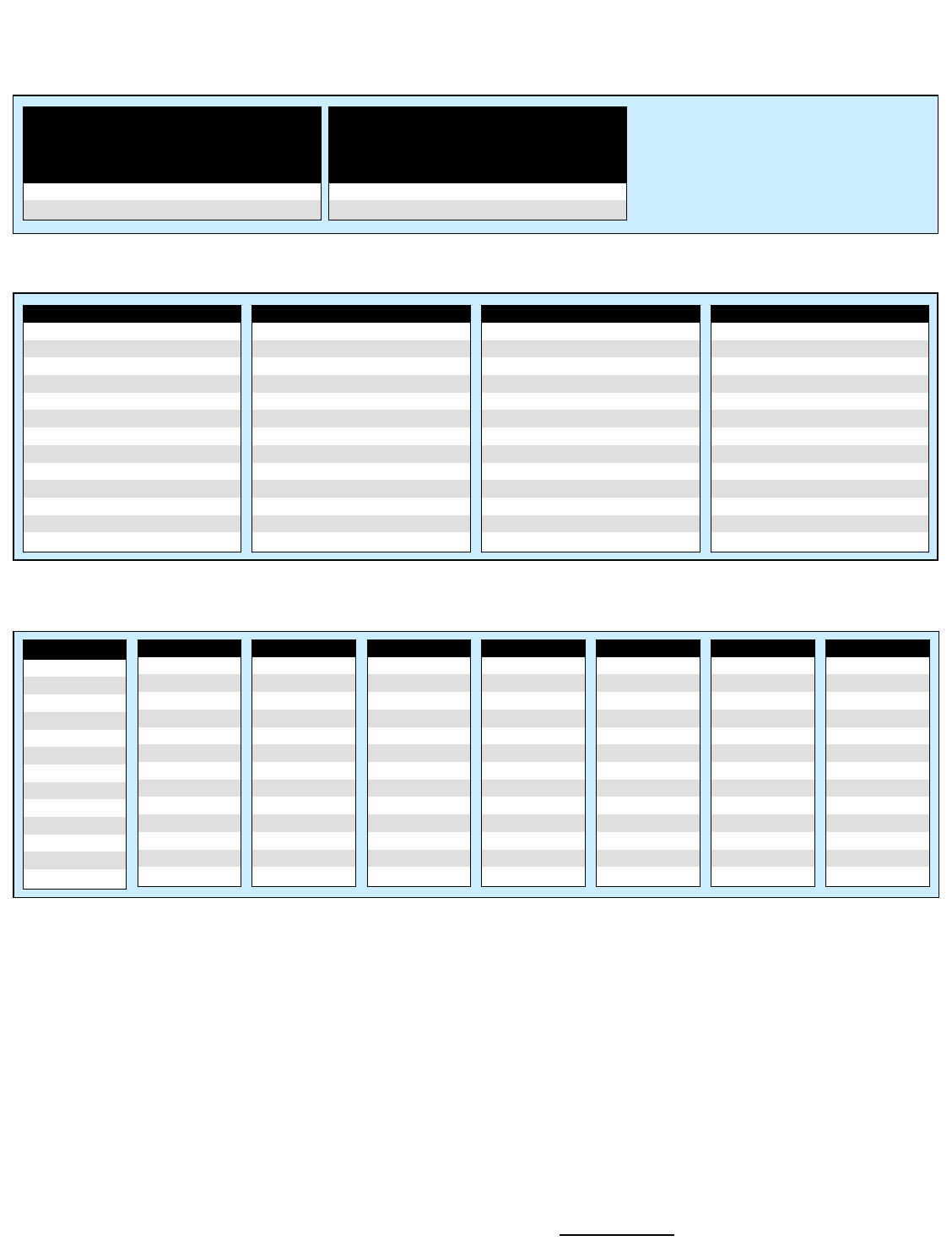
Code Feature Key Description
2-Tone Codes
90 See Note See Note 2-Tone codes can be used for Paging or GateGuard® switch
91 330.5 569.1 operation.
92 349.0 600.9 If the Callbox displays 2-Tone Code “90” on readout it has been
93 368.5 634.5 programmed for custom frequencies.
94 389.0 669.9 When the callbox is programmed for 2-Tone Decode operation, it is
95 410.8 707.3 recommended that you do NOT use QC Tone Codes greater than “23”
96 433.7 746.8 (146.2 Hz).
97 457.9 788.5
98 483.5 832.5
99 330.5 600.9
DTMF and Selcall Codes
1 + xxx DTMF Enter “1” and 3-7 DTMF digits for Primary Decode (0123456789)
2 + xxx Selcall Enter “2” and 3-7 Selcall digits for Primary Decode. (0123456789)
Secondary 2-Tone, DTMF and Selcall Codes
3 + xx 2-Tone Enter “3” and the 2-digit 2-tone code for Secondary Decode
31 + xxx DTMF Enter “31” and 3-7 DTMF digits for Secondary Decode (0123456789)
32 + xxx Selcall Enter “32” and 3-7 Selcall digits for Secondary Decode. (0123456789)
Operation Codes
401 No Switch Disables all switch, paging and Listen In operation. No decoding required.
402 No Switch, Paging Paging enabled uses Primary Decode code only.
403 No Switch, Listen In Listen In operation uses Secondary code only.
404 No Switch, Paging, Listen In Paging operation using Primary Decode code, Listen In operation using
Secondary Decode code.
405 Switch On when called Switch closes (e.g. strobe light turns on) when Callbox 1st receives a call.
Switch opens (e.g. stobe light turns off) as soon as the PTT is pressed, or if the
Callbox has not been used (transmit or receive) for a period of time longer than
RQX Reset Time. No decoding required.
406 Switch On when called, Paging Paging enabled uses Primary Decode code only.
407 Switch On when called, Listen In Listen In operation uses Secondary code only.
408 Switch On when called, Paging, Listen In Paging operation using Primary Decode code, Listen In operation using
Secondary Decode code.
409 Switch On when active Switch is closed (e.g. strobe light turns on) as long as Callbox is in use. Switch
opens (e.g. stobe light turns off) when Callbox has not been used (transmit or
receive) for a period of time longer than RQX Reset Time. No decoding
required.
410 Switch On when active, Paging Paging enabled uses Primary Decode code only.
411 Switch On when active, Listen In Listen In operation uses Secondary code only.
412 Switch On when active, Paging, Listen In Paging operation using Primary Decode code, Listen In operation using
Secondary Decode code.
413 Switch On when active with Turn Off code Switch is closed (e.g. strobe light turns on) when the Callbox receives or
transmits a message, and will remain on until the correct 2-Tone, DTMF or
Selcall or NXDN Secondary Decode Code is received. No Primary code
required.
414 Switch On when active with Turn Off code Paging enabled uses Primary Decode code. Secondary code is used for
Paging Switch Turn Off.
415 GateGuard® Switch momentary Switch is closed for 1 second when the correct 2-Tone, DTMF or Selcall or
NXDN Primary Decode Code is received. No Secondary Decode code
required.
416 GateGuard® Switch momentary, Listen In Momentary switch operation uses Primary Decode Code, Listen In uses
Secondary Decode code.
417 GateGuard® Switch toggle Switch alternately closes and opens when the correct 2-Tone, DTMF or Selcall
or NXDN Primary Decode Code is received. No Secondary Decode code
required.
418 GateGuard® Switch toggle, Listen In Toggle switch operation uses Primary Decode Code, Listen In uses Secondary
Decode code.
419 GateGuard® Switch On/Off code Switch is closed when the correct 2-Tone, DTMF or Selcall or NXDN Primary
Decode Code is received, and opened when the correct 2-Tone, DTMF or
Selcall or NXDN Secondary Decode Code is received.

RQX XD-Series Wireless Callbox Field Programming
Have questions? Call 800-USA-1-USA (800-872-1872) or visit our website at www.ritron.com 17
TABLE 4: PAGING,
GATEGUARD
®
AND LISTEN IN
DECODE CODES
Code Feature Key Description
Primary Decode Features
510 Primary Ring Tone OFF No Ring signal on Primary decode.
511 Primary Ring Tone ON Callbox will sound a Ring signal in the speaker upon Primary decode.
520 Primary Transpond OFF No Transpond transmission on Primary decode.
521 Primary Transpond ON Callbox will transmit a Transpond tone to acknowledge Primary decode.
530 Primary Decode without subtone Primary Decode code is decoded with or without subtone present.
531 Primary Decode with subtone Primary Decode code is only decoded with the correct subtone present.
Secondary Decode Features
550 Secondary Ring Tone OFF No Ring signal on Secondary decode.
551 Secondary Ring Tone ON Callbox will sound a Ring signal in the speaker upon Secondary decode.
560 Secondary Transpond OFF No Transpond transmission on Secondary decode.
561 Secondary Transpond ON Callbox will transmit a Transpond tone to acknowledge Secondary decode
570 Secondary Decode without subtone Secondary Decode code is decoded with or without subtone present.
571 Secondary Decode with subtone Secondary Decode code is only decoded with the correct subtone present.
Listen In Time Features
581 Listen In 5 seconds The Callbox will automatically transmit for a period of time equal to the Listen
582 Listen In 10 seconds In Time when the correct 2-Tone, DTMF or Selcall or NXDN Secondary
Decode Code is
583 Listen In 20 seconds received.
584 Listen In 30 seconds
KEY: The Callbox is set from the factory with these options enabled.
RQX XD-Series Wireless Callbox Field Programming
Have questions? Call 800-USA-1-USA (800-872-1872) or visit our website at www.ritron.com 18
H
OW TO
F
IELD
P
ROGRAM
DTMF
OR
S
ELCALL
E
NCODE
ANI
(T
RANSMIT
)
C
ODES
(
ANALOG ONLY
) ......................................................................
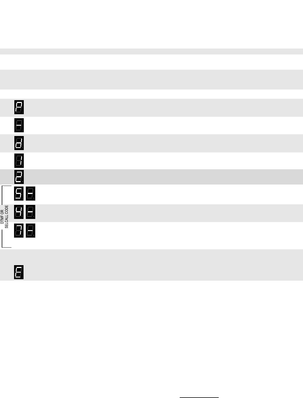
Each Callbox can be uniquely identified by programming for DTMF or Selcall encode ANI (transmit) operation. The user is able to
field program the radio for any 3-7 digit DTMF or Selcall sequence. The radio will transmit the ID code at the beginning of each
transmission. In our example we will program an RQX-41NX to operate with a DTMF ANI Code of “547”.
1. Write down the desired DTMF or Selcall ANI code.
2. Loosen the (4) captive screws in the front corners of the case. These screws are captive to the housing; to
prevent damaging them, DO NOT remove the screws from the housing.
3. Separate the case front from the case back, leaving the batteries connected to the radio. Make sure the
unit has batteries installed.
NOTE: The voltage of the batteries must be greater than 3.3 VDC to program properly.
4. Press and release the ON/PTT button on the front of the unit to turn the radio on.
5. Press and HOLD the Program Button (See FIG-2 on page 7 for location). A "P" will appear on the program
display as you enter program mode and the radio will beep rapidly.
6. Release the program button after the beeping has stopped. The radio will emit a triple beep indicating that
the radio is in program mode and a hyphen will appear on the program display.
7. Click the Program button until the program display shows the Program Code “d”. Pause—the radio will
sound a low tone and show a hyphen across the center of the display to indicate that it is ready to accept a
3 to 7-digit DTMF or Selcall encode ANI sequence.
8. FOR DTMF CODES ONLY – Enter a “1”
9. FOR SELCALL CODES ONLY – Enter a “2”
10. Enter the 1st digit of the DTMF or Selcall code by clicking the Program button until the program display
shows the desired number. Pause—the radio will sound a low tone and show a hyphen across the center
of the display to indicate that it is ready to accept the next digit.
11. Enter the 2nd digit of the DTMF or Selcall code by clicking the Program button until the program display
shows the desired number. Pause—the radio sounds a low tone and will show a hyphen across the center
of the display to indicate that it is ready to accept the next digit.
12. Enter the 3rd digit of the DTMF or Selcall decode sequence by clicking the Program button until the
program display shows the desired number. Pause—the radio sounds a low tone and will show a hyphen
across the center of the display to indicate that it is ready to accept the next digit. Continue entering up to
seven digits.
13. Press and release the ON/PTT button to save your programming. A triple beep will sound to indicate that
programming was successful and a hyphen will appear on the program display. The radio is now ready for
another program entry.
NOTE: An error tone will sound if you attempt to save an incorrect code, an "E" will appear on the display.
Check the digits you are attempting to enter, then re-enter.
14. Once you have made your final program entry, press the ON/PTT button a final time to turn the radio off.
Turn the radio back on for normal operation.
547
RQX XD-Series Wireless Callbox Field Programming
Have questions? Call 800-USA-1-USA (800-872-1872) or visit our website at www.ritron.com 19
H
OW TO
F
IELD
P
ROGRAM
F
EATURE
C
ODES
..............................................
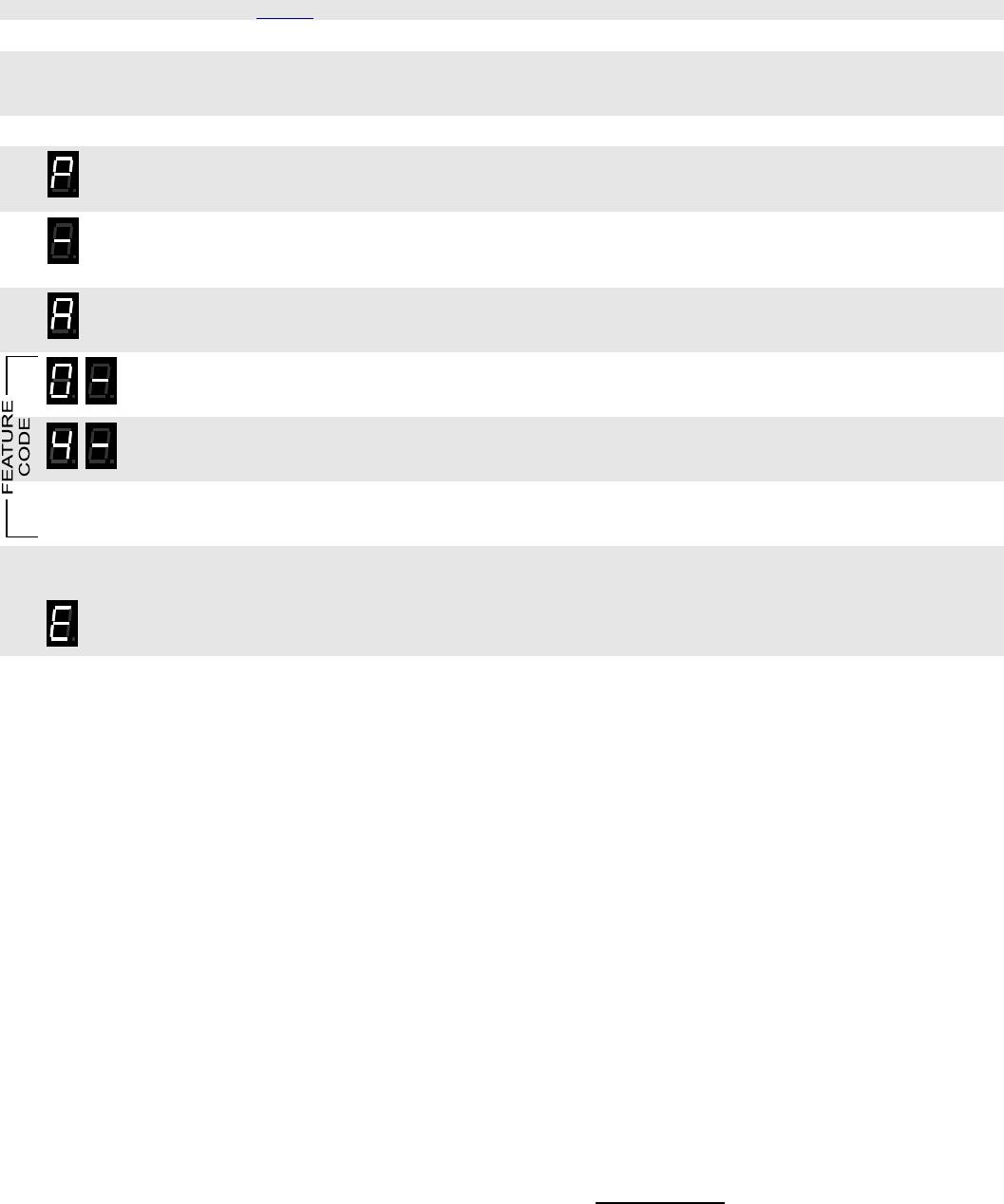
The XD-Series Callbox can be field programmed for a number of advanced features. Refer to Table 5 for the two or three digit
codes available for field programming. In our example we will program an RQX-417 for an RQX Reset Time of 30 seconds.
1. Refer to Table 5 to determine the two or three-digit feature code and write it down.
2. Loosen the (4) screws in the front corners of the case.
3. Separate the case front from the case back, leaving the batteries connected to the radio. Make sure the
unit has batteries installed.
NOTE: The voltage of the batteries must be greater than 3.3 VDC to program properly.
4. Press and release the ON/PTT button on the front of the unit to turn the radio on.
5. Press and HOLD the Program Button (See FIG-2 on page 7 for location). A "P" will appear on the program
display as you enter program mode and the radio will beep rapidly.
6. Release the program button after the beeping has stopped. The radio will emit a triple beep indicating that
the radio is in program mode and a hyphen will appear on the program display.
7. Click the Program button until the program display shows the Program Code “A”. Pause—the radio will
sound a low tone and show a hyphen across the center of the display to indicate that it is ready to accept a
2-digit or a 3-digit Feature code.
8. Enter the 1st digit of the feature code by clicking the Program button until the program display shows the
desired number. Pause—the radio will sound a low tone and show a hyphen across the center of the
display to indicate that it is ready to accept the next digit.
9. Enter the 2nd digit of the feature code (if necessary) by clicking the Program button until the program
display shows the desired number. Pause—the radio sounds a low tone and will show a hyphen across the
center of the display to indicate that it is ready to accept the next digit.
10. Enter the 3rd digit of the feature code (if necessary) by clicking the Program button until the program display
shows the desired number. Pause—the radio sounds a low tone and will show a hyphen across the center
of the display to indicate that it is ready to accept the next digit.
11. Press and release the ON/PTT button to save your programming. A triple beep will sound to indicate that
programming was successful and a hyphen will appear on the program display. The radio is now ready for
another program entry.
NOTE: An error tone will sound if you attempt to save an incorrect code, an "E" will appear on the display.
Check the digits you are attempting to enter, then re-enter.
12. Once you have made your final program entry, press the ON/PTT button a final time to turn the radio off.
Turn the radio back on for normal operation.
04

RQX XD-Series Wireless Callbox Field Programming
Have questions? Call 800-USA-1-USA (800-872-1872) or visit our website at www.ritron.com 20
T
ABLE
5:
A
DVANCED
F
EATURE
C
ODES
................................................
Code Feature Key Description
RQX Reset Time
01 5 seconds RQX Reset Time is the length of time the RQX Callbox can remain inactive (not
02 10 seconds receiving or transmitting) before it automatically shuts off.
03 20 seconds
04 30 seconds
05 45 seconds
06 1 minute
07 2 minutes
08 3 minutes
09 4 minutes
Special Features
21 Reset to Factory Defaults Resets all Callbox features that can be field programmed to Factory default
programming.
22 Display Radio Revision Callbox will display a sequence of 6 digits to identify operating code revision. This is
helpful when troubleshooting the radio.
230 Disable external power loss alert Disables the External +12 VDC “Loss of power” notification and reverts back to “Low
Battery” notification.
231 Enable external power loss alert Enables the External +12 VDC “Loss of power” notification feature.
240 Disable Auto Turn-Off Callbox will remain on at all times. This mode of operation is not recommended for
battery-powered applications.
241 Enable Auto Turn-Off Callbox will automatically turn off when it has not been used (transmit or receive) for a
period of time longer than the RQX Reset Time.
250 Disable Busy Channel TX Inhibit Callbox will transmit whenever the PTT is pressed, regardless of any received signal.
251 Enable Busy Channel TX Inhibit Callbox cannot transmit when there is a received signal. A “busy signal” will be heard
on the Callbox speaker when the PTT is pressed and a received signal is present.
260 Fixed Mic Gain Places the microphone into a fixed gain mode which can be experientally determined
by selection various settings for the input gain from 0 to 255. Lower fixed gains may
be desired for high background ambient noise situations. This number can only be
programmed via PC.
261 Mic Gain is AGCed Microphone gain adjusts to the loudness of the speaker’s voice. Higher background
noise will be present compared to fixed gain.
270 Companding OFF Turns Companding off.
271 Companding ON Companding will compress transmit audio before sending it, and expand receive audio
before it is heard on the speaker to reduce the background noise common in radio
communications. Companding is not recommended unless all radios in the system are
companded.
280 Call Tone OFF Disables Call Tone.
281 Call Tone ON - Low When PTT button is initially pressed a Call Tone will be transmitted at a low level.
282 Call Tone ON – High When PTT button is initially pressed a Call Tone will be transmitted at a high level.
Record Voice Messages
31 Voice Alert (4 sec. max) Once recorded, the message is transmitted when the PTT is 1st pressed.
32 Greeting Message (12 sec. max) Once recorded, the message plays on speaker when the PTT is 1st pressed.
33 Sensor Detect On (4 sec. max) Once recorded, the messae is transmitted when the Sensor Input is pulled low.
34 Sensor Detect Off (4 sec. max) Once recorded, the message is transmitted when the Sensor Input is pulled high.
35 Low Battery (4 sec. max) Once recorded, the message is transmitted when low battery voltage is detected.
36 Power Fail (4 sec. max) Once recorded, the message is transmitted when a +12VDC power fail is detected.
Play Voice Messages
41 Voice Alert Plays the recorded message on the speaker for review.
42 Greeting Message
43 Sensor Detect On
44 Sensor Detect Off
45 Low Battery
46 Power Fail
KEY: The Callbox is set from the factory with these options enabled.

RQX XD-Series Wireless Callbox Field Programming
Have questions? Call 800-USA-1-USA (800-872-1872) or visit our website at www.ritron.com 21
T
ABLE
5:
A
DVANCED
F
EATURE
C
ODES
(C
ONTINUED
)
................................
Code Feature Key Description
Erase Voice Messages
51 Voice Alert Erases the recorded message.
52 Greeting Message
53 Sensor Detect On
54 Sensor Detect Off
55 Low Battery
56 Power Fail
Resend Voice Alert Message
60 0 Re-Sends Number of times the Voice Alert message will be resent. The period of time between
61 1 Re-Sends resends is the RQX Reset Time. Resend is terminated when the Callbox receives a
62 2 Re-Sends response transmission.
63 3 Re-Sends
64 4 Re-Sends
65 5 Re-Sends
Programming Readout Codes
81 Frequency Code Display will sequentially show the programmed 2 or 3-digit Frequency Code. (1)
82 QC or DQC Tone Code Display will sequentially show the programmed 2-digit QC Tone Code or 3-digit DQC
Tone Code. (2)
83 2-Tone, DTMF or Selcall Display will sequentially show the programmed 2-digit 2-Tone Code, or the 3 to 7-digit
Decode Code DTMF or Selcall Code. (3)
84 RQX Reset Time Display will sequentially show the programmed 2-digit RQX Reset Time Code.(5)
85 Switch Operation Display will sequentially show the programmed 2-digit Switch Operatiion Code.
86 Listen In Time Display will sequentially show the programmed 2-digit Listen In Time Code. (4)
87 Receive Volume Level Display will sequentially show the programmed 2-digit Receive Volume Level Code.(4)
88 DTMF or Selcall Encode Code Display will sequentially show the programmed 3 to 7-digit DTMF or Selcall Code.
NXDN Enable Codes
91 analog narrowband mode enabled
92 set to wideband analog (not allowed by FCC in the USA)
93 set to NXDN narrowband digital
94 set to NXDN super-narrowband digital
NXDN Mode Readout
99 analog or NXDN readout Display will show 1 for narrowband analog, 2 for wideband analog, 3 for narrowband
digital and 4 for super-narowband digital.
KEY: The Callbox is set from the factory with these options enabled.
NOTES: (1) 999 indicates a non-table frequency or that TX and RX are not the same
(2) If the RX and TX tone code is not the same, or if DCS is inverted you will get
an ERROR indication
(3) Primary Decode code will be displayed.
(4) ERROR indication will be displayed if not a Field Programming value (has
been PC programmed)

RQX XD-Series Wireless Callbox Programmable Features
Have questions? Call 800-USA-1-USA (800-872-1872) or visit our website at www.ritron.com 22
PC
P
ROGRAMMABLE
XD-S
ERIES
C
ALLBOX
F
EATURES
...............................
The XD-Series Callbox has a variety of programmable features that determine how your callbox operates. Some of these features
can be Field Programmed (FP) by you without using special tools, while other features can only be Programmed (PC) with a PC
and RQX Series PC Programmer RQX-PCPS-1.0 or higher. Contact your Ritron dealer or the factory for details.
Glossary of Terms
Intercom Mode The Automatic Turn-Off feature has been disabled and the Callbox is able to receive calls at any time.
Sleep (analog) If Automatic Turn-Off is DISABLED and Battery Saver is ENABLED the Callbox will go into a low current Sleep
Time when it is not being used, waking up periodically to check for a received message. Pressing the ON/PTT
button will wake-up the radio immediately.
Wake-Up (analog) When Battery Saver is ENABLED and the Callbox has entered the low current Sleep state, the radio will wake-
up periodically to check for a received message. The Sleep Time is set by the Battery Saver Sleep Time.
No Activity Time A continuous period of time where the Callbox is not sending or receiving a call.
T
ABLE
6:
PC
P
ROGRAMMABLE
F
EATURES
.............................................
Feature Key Description
Field Programming Enable This option is ENABLED as the Factory Default setting. This permits all Field
Programmable features (FP) to be field programmed by you. If DISABLED, the features
can only be programmed using special Ritron PC Programming software.
Send Call Tone The Factory Default setting has the Call Tone feature ON (refer to “HOW TO FIELD PROGRAM
FEATURE CODES” on page 19). The callbox can be programmed to transmit a Call Tone if
the Reset Time has expired and the ON/PTT button is pressed. This will alert system users
that the call is originating from the callbox.
Speaker Volume The Factory Default setting is medium volume. Field Programming or PC Programming
allows any volume level between 20 – 100%. A lower speaker volume reduces audio
distortion and provides a more natural sound. For best performance, do not set the volume
any higher than is necessary for your application.
Automatic Turn-Off This feature is ENABLED as the Factory Default setting. The callbox will turn OFF when the
RQX Reset Time has expired. The Reset Time is a pre-programmed amount of time of “no
activity” (no calls transmitted, no calls received) before the callbox turns OFF in order to
conserve battery life. The callbox can be turned back ON when the ON/PTT button is
pressed. This is the recommended mode of operation for all battery only powered
applications.
If Automatic Turn-OFF is NOT selected the callbox does NOT completely turn OFF, but
remains in the Intercom mode, allowing the callbox to receive calls at any time.
Operating the callbox with Automatic Turn-Off DISABLED significantly increases battery
drain, and is therefore NOT recommended for battery only powered applications. Battery life
can be increased using the Battery Saver Enable feature detailed in this section.
RQX Reset Time Set from the factory for 10 seconds, the RQX Reset Time can be Field Programmed to 9
different times ranging from 5 seconds to 4 minutes, and PC programmed for 5-255
seconds. A shorter RQX Reset Time will result in increased battery life. In standard
Automatic Turn-Off operation a longer RQX Reset Time will allow more time for a response
before the Callbox turns off.
RQX Reset Time defines the Inactivity Time allowed before the Callbox:
• Turns Off if Automatic Turn-Off is ENABLED.
• Enters Battery Saver mode if Battery Saver is ENABLED.
• Resets 2-Tone, DTMF or Selcall Paging Decode.
• Automatically opens the Switch output.
KEY: Feature is Field Programmable.

RQX XD-Series Wireless Callbox Programmable Features
Have questions? Call 800-USA-1-USA (800-872-1872) or visit our website at www.ritron.com 23
T
ABLE
6:
PC
P
ROGRAMMABLE
F
EATURES (
CONTINUED
)
............................
Feature Key Description
Battery Saver Enable When the XD-Series Callbox is programmed to operate with Automatic Turn-Off disabled,
Battery Saver can increase battery life in both internal and external battery powered
applications.
With Battery Saver Enable, the callbox will periodically Wake-Up and listen for a received
signal before returning to a low current Sleep state. The time between Wake-Up states can
be PC programmed between 0.5 - 8 seconds with the Battery Saver Sleep Time setting. A
longer time between Wake-Up states will result in increased battery life.
The callbox immediately leaves Battery Saver mode any time the ON/PTT Button is
pressed or a signal is received, and will not return to Battery Saver until the period of no
activity exceeds the RQX Reset Time.
Power Fail Alert Tone By selecting the +12 VDC Power Fail Alert Tone feature the callbox will look for a loss of the
+12 VDC power source. The callbox will immediately transmit an Alert Tone to notify
personnel that the +12 VDC source has been lost and is now operating on battery back-up.
The callbox will transmit an Alert Tone once every hour until the +12 VDC power source is
restored or until the back-up batteries are exhausted. Even if this feature is NOT selected, it
will always revert to Back-up Battery power, see page 5 for details.
Microphone Gain The Microphone can be placed in FIXED or AGC gain mode. The AGC mode generaly
works well for applications where the speakers voice level can varry greatly. However is
quite periods of speech background noise will rise due to increasing gain. In high
background noise applications, using the fixed gain mode with a lower number programmed
in the text box will decrease background noise transmitted by the Callbox. The caller will
need to get closer to the callbox when speaking but overall background noise will be less.
The fixed gain is programmable from 0 to 255.
Listen In Listen In allows remote activation of the Callbox transmitter for a programmed period of
time when the correct 2-Tone, DTMF or Selcall or NXDN code is decoded.
This feature, turned OFF by default, can be Field Programmed to 4 different transmit times
ranging from 5-30 seconds and PC programmed for 1-255 seconds.
The 2-Tone, DTMF or Selcall or NXDN Decode Code required to activate the feature can
be Field Programmed from the 9 different 2-Tone Decode Codes in Table 4, 3-7 digit
DTMF, Selcall codes or 5 digit NXDN ID, or PC programmed for any 2-Tone frequency pair
between 300-1500 Hz.
Busy Channel TX Inhibit With this feature enabled the Callbox cannot transmit when there is a received signal. A
“busy signal” will be heard on the Callbox speaker when the PTT is pressed and a received
signal is present. Busy Channel TX Inhibit is disabled from the factory.
Sensor/Contact Closure Input (not programmed) The Callbox will send a warning tone when a change in the Sensor Input is detected. The
Sensor Input will respond to an OPEN or CLOSED switch.
Transmit Beep Enable This feature is turned on from the factory to provide a short beep in the Callbox speaker any
time the ON/PTT button is pressed. This assures the Callbox user that the radio has turned
on and is ready to transmit their message. With this feature disabled the Callbox will only
beep when the radio is first turned on.
RX Courtesy Beep Enable In high noise environments it is sometimes difficult to determine when a received message
has ended. With the RX Courtesy Beep enabled the Callbox will sound a short beep on the
speaker at the end of each received transmission.
TX Time Out Time Set from the factory for 60 seconds, the TX Time Out Time can be PC programmed for 1-
255 seconds. This sets the length of time the Callbox can transmit continuously. If the
ON/PTT button is held down longer then the TX Time Out Time will allow, the radio will stop
transmitting and a “Busy Signal” will be heard in the speaker until the button is released.
DTMF or Selcall ANI The RQX can be programmed to send a 3-7 digit DTMF or Selcall ANI code at the
beginning of each transmission for radio identification. (analog only)
Companding The Factory Default setting for Companding is OFF (NOT selected). The radio can be
programmed to ENABLE or DISABLE audio companding. Companding will compress
transmit audio before sending it, and expand receive audio before it is heard on the speaker
to reduce the background noise common in radio communications. (analog only)
KEY: Feature is Field Programmable.

RQX XD-Series Wireless Callbox Programmable Features
Have questions? Call 800-USA-1-USA (800-872-1872) or visit our website at www.ritron.com 24
I
NTERCOM
(A
LWAYS
O
N
)
P
ROGRAMMING
.............................................
The XD-Series Callbox can be Field or PC programmed by the factory or by your Ritron dealer to operate as a two-way intercom.
When operating as an intercom the Automatic Turn-Off must be DISABLED so that the radio will remain ON in a “intercom” mode.
The callbox can receive a call from another radio at any time. The higher current requirements of Intercom operation make it
undesirable in battery powered only installations. It is recommended that you power the callbox using +12 VDC capability. See page
5.
Required Radio Programming:
Automatic Turn-Off....................................................................................................................... (Field or PC Programmable)
This feature must be DISABLED via Field or PC programming for the callbox to remain ON at all times.
Other Programmable Features to Consider:
Battery Saver ...................................................................................................... (PC Programmable)
Battery Saver can be used to increase battery life in battery powered applications. With Battery Saver enabled, the callbox will
periodically “wake-up” and listen for a received signal before returning to a low current “sleep” mode. The Sleep Time can be
PC programmed between 0.5 - 8 seconds. A longer sleep time will result in increased battery life, but may result in missed
calls.
Busy Channel TX Inhibit .............................................................................................................. (Field or PC Programmable)
If ENABLED this feature prevents you from talking over someone else on the same channel even if they are using a different
tone code. The radio will beep a series of long, low tones that sounds like a “busy signal” when you press the ON/PTT button.
F
EATURES TO USE WITH
I
NTERCOM
(A
LWAYS
O
N
)
P
ROGRAMMING
Programming for Selective Calling:
2-Tone, DTMF or Selcall or NXDN Paging Decode ..................................................................... (Field or PC Programmable)
This allows selective calling to a XD-Series Callbox in a radio system where there is more than one Callbox. When the Callbox
is programmed for 2-tone, DTMF or Selcall or NXDN decode in Intercom (Always-On) mode it will sound an alert tone on the
Callbox speaker, similar to a telephone ring tone, whenever the 2-tone, DTMF or Selcall or NXDN page has been successfully
decoded. This will alert any users in the immediate area that there is an incoming call on the Callbox.
Ring Tone ....................................................................................................................................... (Field or PC Programmable)
Ring Tone must be set to sound the alert tone on the Callbox speaker when a 2-Tone, DTMF or Selcall or NXDN Page is
successfully decoded. Ring Tone is enabled from the factory.
2-Tone Monitor Trip .................................................................................................................................... (PC Programmable)
This can be set when used with 2-Tone. DTMF or Selcall decode to allow the Callbox to hear all radio traffic on the channel
after it has successfully decoded the correct code, regardless of QC or DQC programming.
Normal conversation will follow after the 2-tone, DTMF or Selcall code is decoded.
If the ON/PTT button is pressed the Callbox returns to QC or DQC decode operation.
The radio will automatically reset back to 2-tone, DTMF or Selcall decode after the RQX Reset Time has expired.
Switch Output Programming:
Switch on When Called ................................................................................................................. (Field or PC Programmable)
This will close the internal Switch Output whenever the radio receives a call after an Inactivity Time that exceeds the RQX
Reset Time. The switch will remain closed until the ON/PTT button is pressed or the RQX Reset Time expires. The Switch
Output could be used to turn on a light or activate an alarm to notify users in the area that an incoming call was present.

RQX XD-Series Wireless Callbox Programmable Features
Have questions? Call 800-USA-1-USA (800-872-1872) or visit our website at www.ritron.com 25
S
WITCH
O
UTPUT
O
PTIONS (A
LLOWS
C
ONTROL OF AN
E
XTERNAL
D
EVICE
) .................
(e.g., a gate controller, a strobe light, or any relay controlled device.)
The XD-Series switch output is a simple 3-Amp relay contact closure that can be used to OPEN and CLOSE a gate, switch on a
light, sound an alarm or any other application where remote control of an ON/OFF switch is required. The XD-Series Callbox can be
programmed to OPEN and CLOSE the Switch Output when one of the following programmed conditions is met.
The XD-Series Callbox can be programmed to alternately OPEN and CLOSE the switch using a single 2-tone, DTMF or Selcall or
NXDN code, or can be PC programmed for separate OPEN and CLOSE codes. Field programming offers 3-7 digit DTMF or Selcall
or NXDN codes, or nine 2-tone codes that correspond to field programmable 2-tone codes available in select RITRON portable and
base radios. NXDN IDs can range from 1 to 65519.
No Switch........................................................................................................................................... (Field or PC Programmable)
Select this option for no switch operation.
Switch On When Called ............................................................................................................... (Field or PC Programmable)
With this option selected the switch will CLOSE when the Callbox first receives a call. The switch will remain CLOSED until the
ON/PTT button is pressed or the RQX Reset Time expires. This option is not applicable if the Callbox is programmed for Automatic
Turn-Off.
Switch On When Callbox in Use .............................................................................................. (Field or PC Programmable)
This option will CLOSE the switch when the Callbox first sends or receives a call. The switch will remain closed until the RQX Reset
Time expires, which also turns the radio off if it is programmed for Automatic Turn-Off.
Switch On When Active with Turn-Off Code ...................................................................................... (Field or PC Programmable)
This option operates the same as Switch On When Callbox in Use with the added ability to OPEN the switch when a unique 2-Tone,
DTMF or Selcall or NXDN Turn-Off Code is received. Unlike the Switch On When Callbox in Use feature, the switch will not OPEN
when the RQX Reset Time expires unless the Callbox is programmed for Automatic Turn-Off. See “2-TONE, DTMF OR SELCALL
DECODE (RECEIVE) SETTINGS” on page 26 for details on programming a Turn-Off code.
GateGuard® – Momentary for 1 sec. ..................................................................................... (Field or PC Programmable)
With this option selected the switch will momentarily CLOSE when a unique 2-Tone, DTMF or Selcall code is received. The switch
will remain CLOSED for the programmed period of time, programmable for 1-255 seconds. See “2-TONE, DTMF OR SELCALL DECODE
(RECEIVE) SETTINGS” on page 26 for details on programming a 2-Tone, DTMF or Selcall Decode Code.
GateGuard® – Toggle .................................................................................................................... (Field or PC Programmable)
With this option selected the switch will alternately OPEN and CLOSE when it receives a unique 2-Tone, DTMF or Selcall code.
After the code is received the Callbox will transmit a SINGLE BEEP if the switch has been OPENED and a DOUBLE BEEP if the
switch has been CLOSED. The switch will open when the Callbox turns off if it is programmed for Automatic Turn-Off. See “2-TONE,
DTMF OR SELCALL DECODE (RECEIVE) SETTINGS” on page 26 for details on programming a 2-Tone, DTMF or Selcall Decode Code.
GateGuard® – On Code / Off Code .......................................................................................... (Field or PC Programmable)
When this option is selected the switch will CLOSE when a unique 2-Tone, DTMF or Selcall or NXDN code is received, and OPEN
when a 2-Tone, DTMF, Selcall or NXDN Turn-Off code is received. The switch will OPEN when the Callbox turns off if it is
programmed for Automatic Turn-Off. See “2-TONE, DTMF OR SELCALL DECODE (RECEIVE) SETTINGS” on page 26 for details on
programming a Decode Code and a Turn-Off Code.

RQX XD-Series Wireless Callbox Programmable Features
Have questions? Call 800-USA-1-USA (800-872-1872) or visit our website at www.ritron.com 26
2-T
ONE
,
DTMF
OR
S
ELCALL
D
ECODE
(R
ECEIVE
)
S
ETTINGS
(
ANALOG ONLY
)
With the XD-Series Callbox 2-Tone, DTMF, Selcall or NXDN decode can be used to selectively call the Callbox in a system where
multiple radios operate on a single frequency. Alternatively, 2-Tone, DTMF, Selcall or NXDN decode can also be used to operate
the Switch Output built into every XD-Series Callbox.
When the radio is programmed for 2-Tone, DTMF or Selcall Paging Decode code, no call will be heard unless the code has been
successfully decoded or the ON/PTT button has been pressed. After decoding, normal 2-way conversation is possible without the
need for the 2-tone, DTMF or Selcall code. Paging Decode is automatically reset when the RQX Reset Time expires.
When the XD-Series Callbox is programmed for Switch Output or Listen In operation with 2-Tone, DTMF, Selcall or NXDN decode,
regular voice communication is unaffected by the 2-tone, DTMF, Selcall or NXDN code. If a Switch Output Option is selected that
uses 2-tone, DTMF or Selcall decode it cannot be used for Paging Decode.
NOTICE
When the callbox is programmed for 2-Tone Decode operation, it is recommended that you do NOT use QC Tone
Codes greater than “23” (146.2 Hz).
2-Tone Table # ............................................................................................ (Field or PC Programmable)
The XD-Series Callbox comes equipped with 9 pre-determined 2-Tone codes that correspond to table codes that certain RITRON
portable and base radios can send. Use of the 2-Tone Table codes allows programming without the need for the PC programmer.
1st Tone decoded for 1 sec. ................................................................................. (PC Programmable)
You can custom program the 1st tone of the 2-tone code to any frequency between 300-1500 Hz. The 1st tone must be decoded for
the programmed period of time before the radio looks for the 2nd tone. The factory setting for decode time is 1 second.
2nd Tone decoded for 1 sec. ................................................................................ (PC Programmable)
You can custom program the 2nd tone of the 2-tone code to any frequency between 300-1500 Hz.The 2nd tone must be decoded
for the programmed period of time after the 1st tone has been decoded. The factory setting for decode time is 1 second.
All Call decoded for 4 sec. ................................................................................... (PC Programmable)
With 2-Tone All Call enabled you can custom program an All Call tone to any frequency between 300-1500 Hz. The All Call tone
must be decoded for the programmed period of time. All Call can also be achieved with a unique DTMF or Selcall code. All Call is
not enabled as received from the factory.
Ring Tone Enable ......................................................................................... (Field or PC Programmable)
With this feature enabled the Callbox will sound a ring signal in the speaker, similar to a telephone ring, any time the 2-Tone, DTMF,
Selcall or NXDN code, Group Call or All Call code is decoded. Ring Tone is enabled from the factory.
Transpond Enable ........................................................................................ (Field or PC Programmable)
Transpond transmits a tone after a 2-Tone, DTMF, Selcall or NXDN code, Group Call or All Call code has been received to alert the
calling radio that the code was successfully decoded. Transpond is enabled from the factory.
Group Call Decode ................................................................................................. (PC Programmable)
When this option is set, 2-tone decode is achieved if the radio receives the 1st tone for the programmed All Call time. If this option is
selected the All Call time must be longer than the 1st Tone time or the Callbox will always decode on the 1st tone, ignoring the 2nd
tone altogether. Group Call can also be achieved with a unique DTMF or Selcall code. Group Call is not enabled as received from
the factory.
Monitor Trip ........................................................................................................... (PC Programmable)
With this option selected the Callbox will be in carrier squelch mode any time a 2-Tone, DTMF, Selcall or NXDN code is decoded,
regardless of any QC or DQC code programmed in the radio. The radio reverts back to QC or DQC tone decode if the ON/PTT
button is pressed and reverts back to 2-tone, DTMF, Selcall or NXDN decode after the RQX Reset Time has expired. Monitor Trip
is not enabled from the factory.
2-Tone, DTMF or Selcall Decode with Subtone .............................................. (Field or PC Programmable)
With 2-Tone, DTMF or Selcall Decode with Subtone enabled, the Callbox will not decode codes unless the correct subtone is also
present. 2-Tone, DTMF or Selcall Decode with Subtone is not enabled from the factory.
Turn-Off Code .............................................................................................. (Field or PC Programmable)
In certain Switch Output applications a separate 2-Tone, DTMF or Selcall Turn-Off Code is required. This code cannot be the same
as the 2-Tone, DTMF or Selcall Decode Code.

RQX XD-Series Wireless Callbox Voice Messages
Have questions? Call 800-USA-1-USA (800-872-1872) or visit our website at www.ritron.com 27
A
UTOMATIC
V
OICE
M
ESSAGES
............................................................................................................................
The XD-Series Callbox is equipped to use pre-recorded voice messages that notify radio system users when specific events occur. These
unique voice messages are recorded and stored on the Callbox, and automatically played back when the associated event occurs. The
XD-Series Callbox supports 6 different message events and comes from the factory with no messages recorded.
To activate any of the 6 event messages simply record the voice message per the instructions in this manual. The recorded message can
be played back for your review and re-recorded if necessary. You can erase any event message individually if you decide not to utilize that
message.
Greeting Message
The Greeting Message is played on the RQX Callbox speaker when the push-to-talk button is first pressed. This message is used to give
the Callbox user instruction on how to proceed. A typical message might be ‘Welcome to our facility. An attendant will be with you shortly.”
The Greeting Message:
Is played on the RQX Callbox speaker only when the push-to-talk button is first pressed.
Will be re-played every time the push-to-talk button is pressed until the Callbox is answered.
Is not transmitted.
Can be up to 12 seconds long.
Voice Alert Message
The Voice Alert Message is transmitted automatically by the Callbox when the push-to-talk button is first pressed. Often used with the Call
Tone feature, this message alerts radio system users that the Callbox has been activated. Typical messages might be “South delivery
entrance”, “Curbside Lane 4” or “Main gate”.
The Voice Alert Message:
Is transmitted automatically by the Callbox when the push-to-talk button is first pressed.
Will be re-transmitted every time the push-to-talk button is pressed until the Callbox is answered.
Is transmitted after the Greeting Message has played on the speaker. If the Greeting Message is not used, the Voice Alert Message will
be heard on the speaker.
Will not be sent if the radio channel is busy when Busy Channel TX Inhibit feature has been enabled. Instead, it will wait for the channel
to clear before transmitting.
Will be automatically re-transmitted periodically until the Callbox is answered if the Callbox has been programmed with the Automatic ID
Re-Send feature.
Will be sent after the Call Tone if the Call Tone feature is enabled.
Is automatically sent ahead of Sensor Detect or Low Battery/Power Fail messages.
Can be up to 4 seconds long.
Power Fail Message
With the “External +12V Power Fail Alert” enabled the Power Fail Message is automatically transmitted when loss of external power
is detected on the Callbox. It will not be sent if the radio channel is busy, but instead will wait for the channel to clear before
transmitting. Also, the message alert is appended to the existing transmission, and the Call Tone and Voice Alert Message will only
be sent if it was a part of the existing transmission. A typical message might be “Power failure”. The Voice Alert Message is sent
immediately before the Power Fail/ Low Battery Message, so a typical transmission might be “South delivery entrance” followed by “Power
Failure”. Make sure the message is recorded and enabled under the “Message” menu.
.
Low Battery Message
The Low Battery Message is appended to a transmission when low voltage is detected on the 3 D cell battery pack on the Callbox provided
the message is recorded and enabled. A typical message might be “Low battery”
Sensor Detect On Message
The Sensor Detect On Message is automatically transmitted when the Sensor Input is pulled low. Depending on the sensor used, a typical
message might be “Door open”, “Motion detected” or “Vehicle present”. The Voice Alert Message is sent immediately before the Sensor
Detect On Message, so a typical transmission might be “South delivery entrance” followed by “Door open”.

RQX XD-Series Wireless Callbox Voice Messages
Have questions? Call 800-USA-1-USA (800-872-1872) or visit our website at www.ritron.com 28
The Sensor Detect On Message:
Is automatically transmitted when the Sensor Input is pulled low.
Will not be sent if the radio channel is busy, but instead will wait for the channel to clear before transmitting.
Is sent after the Call Tone and the Voice Alert Message if the radio is programmed for those features.
Can be up to 4 seconds long.
Sensor Detect Off Message
The Sensor Detect Off Message is automatically transmitted when the Sensor Input is pulled high. Depending on the sensor used, a typical
message might be “Door closed”, “Motion detected” or “Vehicle present”. The Voice Alert Message is sent immediately before the Sensor
Detect Off Message, so a typical transmission might be “South delivery entrance” followed by “Door closed”.
The Sensor Detect Off Message:
Is automatically transmitted when the Sensor Input is pulled high.
Will not be sent if the radio channel is busy, but instead will wait for the channel to clear before transmitting.
Is sent after the Call Tone and the Voice Alert Message if the radio is programmed for those features.
Can be up to 4 seconds long.
A
UTOMATIC
ID
R
E
-S
END
.....................................................................
The RQX XD-Series Callbox can automatically re-send the Call Tone, Voice Alert Message, and DTMF or Selcall ANI a programmed
number of times when a call is not immediately answered. This allows the Callbox to periodically repeat the Voice Alert Message without
further input from the Callbox user. The periodic rate is determined by the RQX Reset Time.
Following is an example of Automatic ID Re-Send programming and its effect:
The Callbox is field programmed for:
Greeting Message “Welcome to Ritron, someone will be with you shortly”
Voice Alert Message “Main Entrance”
Call Tone ON
Automatic Turn-Off enabled
RQX Reset Time of 20 seconds
Automatic ID Re-Send set to 1
Here is how it will operate:
A guest presses the Callbox On/PTT button and the Greeting Message “Welcome to Ritron, someone will be with you shortly” is heard
on the Callbox speaker.
If the radio channel is not being used the Callbox will transmit the Call Tone, followed by the Voice Alert Message “Main Entrance.” This
will be heard by all system radio users, but not heard on the Callbox speaker.
If the Callbox is not answered within 20 seconds (RQX Reset Time) the Call Tone and Voice Alert Message will be re-transmitted
(Automatic ID Re-Send).
If the Callbox is again not answered within 20 seconds (RQX Reset Time) it will turn off (if Automatic Turn-Off is enabled).
If the Callbox On/PTT button is pressed again at any time before it is answered the entire process described above is re-started.
If the Callbox is answered before it automatically turns off the Callbox operates as normal 2-way radio communication with no messages
or Call Tone.
Using Automatic ID Re-Send to Extend RQX Reset Time
A Voice Alert Message does not have to be used to enjoy the benefits of Automatic ID Re-Send. This feature can also be used to extend
the RQX Reset Time whenever the Callbox On/PTT button is 1st pressed, providing radio users additional time to respond to the Callbox.
For example, if the Callbox is programmed for an RQX Reset Time of 10 seconds and Automatic ID Re-Send of 5, the Callbox will remain
ON for 60 seconds (RQX Reset Time plus RQX Reset Time multiplied by number of Automatic ID Re-Send) after the On/PTT button is 1st
pressed instead of 10 seconds (RQX Reset Time). Once the Callbox has been answered it will turn off after 10 seconds (RQX Reset Time)
of inactivity.
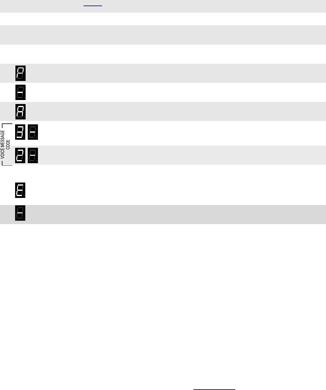
RQX XD-Series Wireless Callbox Voice Messages
Have questions? Call 800-USA-1-USA (800-872-1872) or visit our website at www.ritron.com 29
H
OW TO
R
ECORD A
V
OICE
M
ESSAGE
.......................................................................................................
Recite your voice message a number of times before recording to be sure it can be completed in the time allowed. For best results
speak directly into the Callbox microphone in a slow, clear voice.
1. Refer to Table 5 to determine the two-digit Record Code and write it down.
2. Loosen the (4) screws in the front corners of the case.
3. Separate the case front from the case back, leaving the batteries connected to the radio. Make sure the
unit has batteries installed.
NOTE: The voltage of the batteries must be greater than 3.3 VDC to record properly.
4. Press and release the ON/PTT button on the front of the unit to turn the radio on.
5. Press and HOLD the Program Button (See FIG-2 on page 7 for location). A "P" will appear on the program
display as you enter program mode and the radio will beep rapidly.
6. Release the program button after the beeping has stopped. The radio will emit a triple beep indicating that
the radio is in program mode and a hyphen will appear on the program display.
7. Click the Program button until the program display shows the Program Code “A”. Pause—the radio will
sound a low tone and show a hyphen across the center of the display to indicate that it is ready to accept a
2-digit Record Voice Message Code.
8. Enter the 1st digit of the Record Code by clicking the Program button until the program display shows the
desired number. Pause—the radio will sound a low tone and show a hyphen across the center of the
display to indicate that it is ready to accept the next digit.
9. Enter the 2nd digit of the Record Code by clicking the Program button until the program display shows the
desired number. Pause—the radio sounds a low tone and will show a hyphen across the center of the
display to indicate that it is ready to accept the next digit.
10. Press and release the ON/PTT button.
11. Press and hold the Program button to begin recording the message. Speak directly into the microphone.
NOTE: An error tone will sound if you attempt to enter an incorrect code, an "E" will appear on the display.
Check the digits you are attempting to enter, then re-enter.
12. Release the Program button when you have completed the message. The message will be played back
and a hyphen will appear on the program display. The radio is now ready to record another message, or
for another program entry.
13. Once you have recorded your final message, press the ON/PTT button a final time to turn the radio off.
Turn the radio back on for normal operation.
32
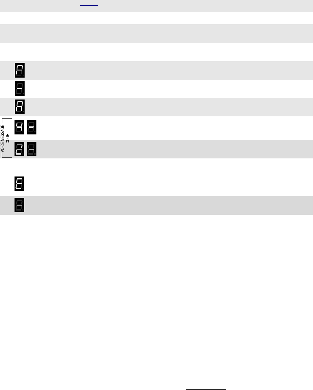
RQX XD-Series Wireless Callbox Voice Messages
Have questions? Call 800-USA-1-USA (800-872-1872) or visit our website at www.ritron.com 30
H
OW TO
P
LAY A
V
OICE
M
ESSAGE
Recorded voice messages can be played back on the Callbox speaker for review.
1. Refer to Table 5 to determine the two-digit Play Code and write it down.
2. Loosen the (4) screws in the front corners of the case.
3. Separate the case front from the case back, leaving the batteries connected to the radio. Make sure the
unit has batteries installed.
NOTE: The voltage of the batteries must be greater than 6 VDC to record properly.
4. Press and release the ON/PTT button on the front of the unit to turn the radio on.
5. Press and HOLD the Program Button (See FIG-2 on page 7 for location). A "P" will appear on the program
display as you enter program mode and the radio will beep rapidly.
6. Release the program button after the beeping has stopped. The radio will emit a triple beep indicating that
the radio is in program mode and a hyphen will appear on the program display.
7. Click the Program button until the program display shows the Program Code “A”. Pause—the radio will
sound a low tone and show a hyphen across the center of the display to indicate that it is ready to accept a
2-digit Play Recorded Message Code.
8. Enter the 1st digit of the Play Code by clicking the Program button until the program display shows the
desired number. Pause—the radio will sound a low tone and show a hyphen across the center of the
display to indicate that it is ready to accept the next digit.
9. Enter the 2nd digit of the Play Code by clicking the Program button until the program display shows the
desired number. Pause—the radio sounds a low tone and will show a hyphen across the center of the
display to indicate that it is ready to accept the next digit.
10. Press and release the ON/PTT button to begin playback of the message. If the message has not been
recorded an error tone will sound and an "E" will appear on the display.
NOTE: An error tone will sound if you attempt to enter an incorrect code, an "E" will appear on the display.
Check the digits you are attempting to enter, then re-enter.
11. Once the message playback is complete a triple beep will sound and a hyphen will appear on the program
display. The radio is now ready to playback another message, or for another program entry.
12. Once you have played your final message, press the ON/PTT button a final time to turn the radio off. Turn
the radio back on for normal operation.
H
OW TO
E
RASE A
V
OICE
M
ESSAGE
If you decide not to use a voice message that is already recorded, it can be easily erased via field programming. Follow the “How to
Play a Voice Message” instructions above using the Erase Code specified in Table 5.
42

RQX XD-Series Wireless Callbox GateGuard® Application
Have questions? Call 800-USA-1-USA (800-872-1872) or visit our website at www.ritron.com 31
C
ONFIGURING THE
C
ALLBOX FOR A
G
ATE
G
UARD
®
A
PPLICATION
........................................................................................................
The XD-Series Callbox can be mounted to virtually any surface with four (4) ¼” panhead screws. Choose a type of screw thread
and screw length which will hold firmly in the surface to which the unit will be mounted.
MOUNTING the XD-Series CALLBOX: ( Refer to FIG-3)
1.
2. Loosen the (4) screws on the front corners of the case and separate the case front from the case back.
3. Program the radio, if required. Refer to the programming section of this manual for details. To program the radio you must
apply 8 to 12 VDC external power, or alkaline batteries.
4. Disconnect the battery holder from the radio and set the case front aside.
5. Carefully drill a hole in the XD-Series Callbox case back as required for your external hook-up cable installation using one of
the pilot locations on the case bottom or back. Extreme care must be taken not to damage the battery holder or batteries while
drilling.
6. Install the 4 mounting brackets to the back of the Callbox case shown on page 8. The mounting brackets can be installed
vertically, as shown, or horizontally.
7. CONNECTING THE SWITCH OUTPUTS TO AN EXTERNAL DEVICE
a. Thread your external hookup cable from the external device you wish to control through the hole with approximately 4
inches of cable inside the XD-Series case.
b. Your external cable will be connected to the Callbox 6-conductor interface cable with wire nuts, dress your external wires
accordingly (Refer to Table 7).
c. With your selected hardware, secure and seal the conduit to ensure moisture and vandal resistant functions to the XD-
Series Callbox case.
Consult the manufacturer of the external device you are attempting to control for the recommended wire gauge.
Confirm that your application will NOT exceed the maximum rating of the on-board relay of 120 VAC @ 3 amp.
Make sure all power to the equipment is turned OFF or disconnected.
CAUTION: The interface cable and wire nuts are to be positioned in the lower part of the case, away from the internal
antenna.
8. Position the XD-Series Callbox case in the chosen installation location and secure it in place with four screws through the
mounting brackets.
9. Reconnect the battery mating connectors between the case front and case back.
10. Fasten the case front to the case back with the four (4) corner screws.
T
ABLE
7:
C
ALLBOX
6-C
ONDUCTOR
I
NTERFACE
C
ABLE
..............................
Pin # Wire Color Description
6 Red External 12 VDC + input
5 Black External 12 VDC - input
4 Blue Switch Output + connection
3 Green Switch Output - connection
2 White Sensor Input + connection
1 Brown Sensor Input - ground
!
!
Due to the wide variety of installation possibilities, RITRON does not provide the cables or hardware required to bring
external connections into the Callbox.
When selecting your cable hardware be sure it will adequately seal the cable to the case.
Carefully study the internal construction of the Callbox and determine the location on the outside case where the
external supply and GateGuard® hook-up will be brought in.
Consider clearance with your desired hardware.
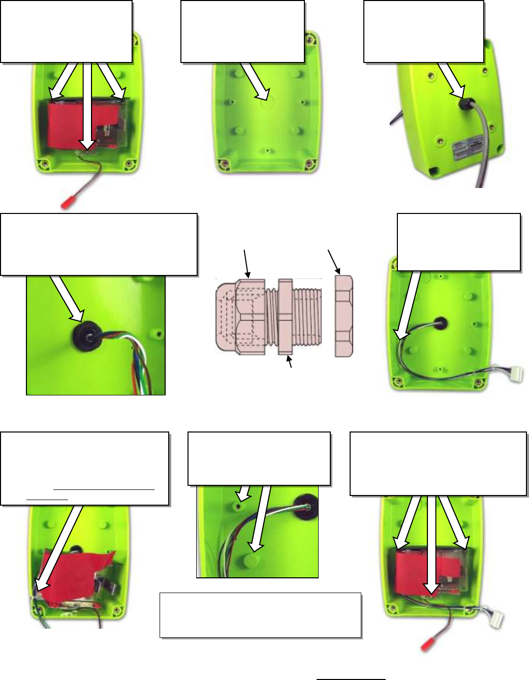
RQX XD-Series Wireless Callbox GateGuard® Application
Have questions? Call 800-USA-1-USA (800-872-1872) or visit our website at www.ritron.com 32
I
NSTALLING THE
C
ALLBOX
6-C
ONDUCTOR
I
NTERFACE
C
ABLE (60201124)
......
Remove the battery holder
and plate from the case
back by removing the
three T10 Torx mounting
screws and washers.
Using the center pilot
hole, drill a 31/64 inch
hole for the cable and
Heyco strain relief/water
seal.
Install the Heyco strain
relief as shown. Thread
the 6-conductor cable
through from the inside.
Carefully route the 6-
conductor cable toward
the inside left edge of
the case as shown.
Pull the 6-conductor through as shown until
there is less than ¼ inch of the gray sleeve
showing through the strain relief. Use the
Inside Retaining Nut to tighten to case, then
tighten the Cable Sealing Nut.
Inside
Retaining
Nut
Outside Retaining
Nut
Sealing
Nut
Use the Cable Tie to secure the 6-
conductor cables to the battery hold-
er as shown. The 6-conductor ca-
bles will run beneath the battery
holder. Do not tighten the Cable Tie
at this time.
Secure the battery holder to the case
back with the three T10 Torx mounting
screws and washers. The 6-conductor
cables are routed beneath the battery
holder as shown.
WARNING! Be sure the wires are
not trapped between the battery
holder and the molded plastic
mounting stud! Wires are routed
below the stud as shown.
Tighten the Tie Wrap after the battery holder
is installed. Connect the 6-Conductor cable to
the RQX Q-Series radio.

RQX XD-Series Wireless Callbox GateGuard® Application
Have questions? Call 800-USA-1-USA (800-872-1872) or visit our website at www.ritron.com 33
H
OW TO
F
IELD
P
ROGRAM THE
XD-S
ERIES
C
ALLBOX FOR
G
ATE
G
UARD
®
O
PERATION
...................................................................
The XD-Series Callbox can be field programmed for basic GateGuard® operation, or PC programmed to suit your unique
requirements. The instructions in this section apply only to Field Programmable features. If PC programming software has
been used to set 2-Tone, DTMF, Selcall or NXDN decode (receive) or other optional GateGuard® features, operation may not be as
described here.
Follow these steps to program the XD-Series Callbox for GateGuard® operation (analog only):
1. Program the frequency and tone codes per the “HOW TO FIELD PROGRAM FREQUENCY & TONE CODES” instructions on page 11.
2. Program the 2-Tone, DTMF or Selcall Decode (Receive) code per the “HOW TO FIELD PROGRAM 2-TONE, DTMF OR SELCALL
DECODE (RECEIVE) OPERATION” instructions on page 13.
3. Program the callbox for GateGuard® Momentary Operation per the “HOW TO FIELD PROGRAM 2-TONE, DTMF OR SELCALL
DECODE (RECEIVE) OPERATION” instructions on page 13.
The XD-Series Callbox will now operate in GateGuard® mode as follows:
The Callbox will be in “Automatic Turn-Off” mode. The ON/PTT button must first be pressed as described in “OPERATING THE
XD-SERIES CALLBOX WITH FACTORY DEFAULT SETTINGS” section on page 3 before normal two-way communications can be
established.
If the Callbox does not send or receive a signal for more than 10 seconds the Callbox will automatically turn off. The ON/PTT
button must be pressed to turn the Callbox back on and receive a call.
When the Callbox receives and decodes the correct 2-Tone, DTMF or Selcall Decode code the Callbox Switch Output will
momentarily CLOSE the switch for 1 second. The Callbox will also automatically transmit a confirmation tone back to the senders
radio notifying them that the correct 2-tone, DTMF or Selcall code has been decoded at the XD-Series Callbox.
O
PTIONAL
G
ATE
G
UARD
®
S
ETTING
/F
EATURES
..........................................
The XD-Series Callbox can be Field Programmed, or PC programmed using special software, for customized GateGuard®
applications.
Automatic Turn-Off........................................................................................................................ (Field or PC Programmable)
This is ENABLED as the Factory Default setting. The callbox will turn OFF when the RQX Reset Time has expired. The Reset Time
is a pre-programmed amount of time of “no activity” (no calls transmitted, no calls received) before the callbox turns OFF in order to
conserve battery life. The callbox can be turned back ON when the ON/PTT button is pressed. This is the recommended mode of
operation for all battery only powered applications.
If Automatic Turn-Off is NOT selected the callbox does NOT completely turn OFF, but remains in the Intercom mode, allowing the
callbox to receive calls at any time.
Operating the callbox with Automatic Turn-Off DISABLED significantly increases battery drain, and is therefore NOT recommended
for battery only powered applications. Battery life can be increased using the Battery Saver Enable feature detailed in this section.
RQX Reset Time .................................................................................................................................... (Field or PC Programmable)
This is set from the factory for 10 seconds, but can be Field Programmed to 9 different times ranging from 5 seconds to 4 minutes,
and PC programmed for 5-255 seconds. A shorter RQX Reset Time will result in increased battery life. In standard Automatic Turn-
Off operation a longer inactivity timer will allow more time for a response before the callbox turns OFF.
Battery Saver Enable ......................................................................................................................................... (PC Programmable)
When the XD-Series Callbox is programmed to operate with Automatic Turn-Off DISABLED, Battery Saver can increase battery life
in both internal or external battery powered applications.
With Battery Saver Enable, the callbox will periodically Wake-Up and listen for a received signal before returning to a low current
Sleep mode. The sleep time can be PC programmed between 0.5 - 8 seconds with the Battery Saver Sleep Time setting. A longer
sleep time will result in increased battery life, but may result in missed calls.

RQX XD-Series Wireless Callbox GateGuard® Application
Have questions? Call 800-USA-1-USA (800-872-1872) or visit our website at www.ritron.com 34
The callbox immediately leaves Battery Saver mode any time the ON/PTT Button is pressed or a signal is received, and will not
return to Battery Saver until the period of no activity exceeds the RQX Reset Time.
O
PTIONAL
G
ATE
G
UARD
®
S
ETTING
/F
EATURES (
CONTINUED
)
.........................
External +12 VDC Power Fail Alert Tone ............................................................................................ (PC or Field Programmable)
By selecting the +12 VDC Power Fail Alert Tone feature the callbox will look for a loss of the +12 VDC power source. The callbox
will immediately transmit an Alert Tone to notify personnel that the +12 VDC source has been lost and is now operating on battery
back-up. The callbox will transmit an Alert Tone once every hour until the +12 VDC power source is restored or until the back-up
batteries are exhausted. Even if this feature is NOT selected, it will always revert to Back-up Battery power, see page 5 for details.
NOTE: In applications where external power is available, we recommend using the RPS-EXPO Cube Power Supply. See page 5
for details.
Send Call Tone ....................................................................................................................................... (Field or PC Programmable)
The Factory Default setting has the Call Tone feature ON (refer to “HOW TO FIELD PROGRAM FEATURE CODES” on page 18). The
callbox can be programmed to transmit a Call Tone if the Reset Time has expired and the ON/PTT button is pressed. This will alert
system users that the call is originating from the callbox.
Ring Tone .............................................................................................................................................. (Field or PC Programmable)
This will sound an alert tone on the callbox speaker, similar to a telephone ring tone, whenever the correct 2-Tone, DTMF, Selcall
or NXDN code has been successfully decoded. This feature is used to alert the Callbox user that the gate is being opened or
closed. Ring Tone is enabled from the factory.
GateGuard® – Toggle ........................................................................................................................... (Field or PC Programmable)
Will alternately open and close the Switch Output when it receives a unique 2-Tone, DTMF, Selcall or NXDN code. After the 2-tone
decode (receive) code is received the callbox will transmit a single beep if the switch has been opened and a double beep if the
switch has been closed. The switch will open when the callbox turns off if it is programmed for Automatic Turn-Off.
GateGuard® On Code / Off Code ......................................................................................................... (Field or PC Programmable)
This operation allows programming of separate ON and OFF 2-Tone, DTMF, Selcall or NXDN Decode (receive) codes. The XD-
Series Callbox will CLOSE the Switch Output upon receiving the ON code, and OPEN the Switch Output upon receiving the OFF
code.
When reading out the radio programming as described in the “HOW TO READOUT CURRENT RADIO FREQUENCY & TONE CODES” section,
the ON code will be displayed.
Relay Polarity
The relay switch output can be set for a normally-open or normally-closed condition depending on the position of the Relay Polarity
Jumper. (See FIG-1)
Sensor/Contact Closure Input
The Sensor Input will detect a logic level and transmit an Alert tone when a change in logic level is detected. Separate alert tones
are used for OPEN (logic level high) tone and CLOSED (logic level low) tone. Additionally, the Sensor Input can be used to turn on
the RQX Callbox with the Sensor Input Jumper in place.
Busy Channel TX Inhibit ...................................................................................................................... (Field or PC Programmable)
This will not allow you to transmit when another user is already transmitting on your radio frequency, even if they are using a
different tone code. The radio will beep a series of long, low tones (like a busy signal) while the ON/PTT button is held down.
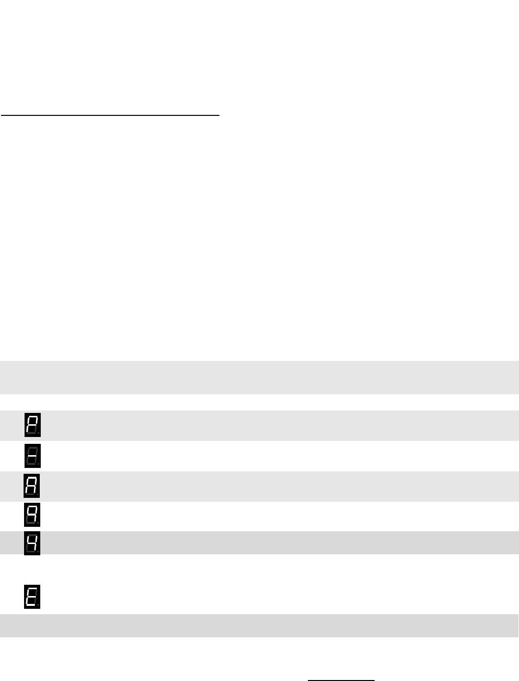
RQX XD-Series Wireless Callbox GateGuard® Application
Have questions? Call 800-USA-1-USA (800-872-1872) or visit our website at www.ritron.com 35
H
OW TO
F
IELD
P
ROGRAM
NXDN
F
EATURES
XD callboxes which are fitted with an NXDN board can be programmed to send NXDN codes such as RAN codes and ID codes.
Each callbox must have its unique subscriber unit ID (SUID) and operate its squelch based on either receiving the proper RAN code
or individual or group ID code. It can also be required to have both the correct RAN code and individual or group ID code. The “all
call” code (65535) can be considered a group call code. Also, the radio’s relay can be closed or opened when an open ID or closed
ID is received. A summary of the program codes and features is shown below in table 8.
T
ABLE
8:
C
ALLBOX
NXND
PROGRAMMING CODES
..................................
display code digits Function
n1 2 RX RAN codes (0-63 for repeater access code)
n2 2 TX RAN codes (0-63 for repeater access code)
n3 1-5 SUID (unique ID transmitted by callbox)
n4 1-5 Group ID (defines “group” the callbox is in and will hear messages)
n5 1-5 primary control ID code
n6 1-5 secondary control ID code
n71 1-5 Individual Destination ID (individual ID the radio will call)
n72 1-5 Group Destination ID (group ID the radio will call)
IDs must be in the 1 to 65519 range. An “n” will set the code and an “r” read out the code.
To read out the code key in “r” followed by a 1 through 7, hit PTT and the code will be displayed digit by digit. For example, if a
group destination ID of 1000 is set, to read out the destination ID key in “r” then “7” and hit PTT. The display will show “2” then
“01000”. Here “2” indicates a group and “1” would mean individual ID.
The NXDN radio will use whatever channel is set up in the regular channel programming section. Digital narrowband (9600 bps) or
super-narrowband (4800 bps) mode can be selected and programmed. Set up for Digital super-narrow band follows:
1. Loosen the (4) captive screws in the front corners of the case. These screws are captive to the housing; to
prevent damaging them, DO NOT remove the screws from the housing.
3. Separate the case front from the case back, leaving the batteries connected to the radio. Make sure the
unit has batteries installed.
NOTE: The voltage of the batteries must be greater than 3.3 VDC to program properly.
4. Press and release the ON/PTT button on the front of the unit to turn the radio on.
5. Press and HOLD the Program Button (See FIG-2 on page 7 for location). A "P" will appear on the program
display as you enter program mode and the radio will beep rapidly.
6. Release the program button after the beeping has stopped. The radio will emit a triple beep indicating that
the radio is in program mode and a hyphen will appear on the program display.
7. Click the Program button until the program display shows the Program Code “A”. Pause—the radio will
sound a low tone and show a hyphen across the center of the display to indicate that it is ready to accept a
2-digit RF channel mode.
8. FOR Digital super-narrowband – Click the Program button until the program display shows a “9”.
9. FOR Digital super-narrowband – Click the Program button until the program display shows a “4”.
10. Press and release the ON/PTT button to save your programming. A triple beep will sound to indicate that
programming was successful and a hyphen will appear on the program display. The radio is now ready for
another program entry.
NOTE: An error tone will sound if you attempt to save an incorrect code, an "E" will appear on the display.
Check the digits you are attempting to enter, then re-enter.
11. Once you have made your final program entry, press the ON/PTT button a final time to turn the radio off.
Turn the radio back on for normal operation.
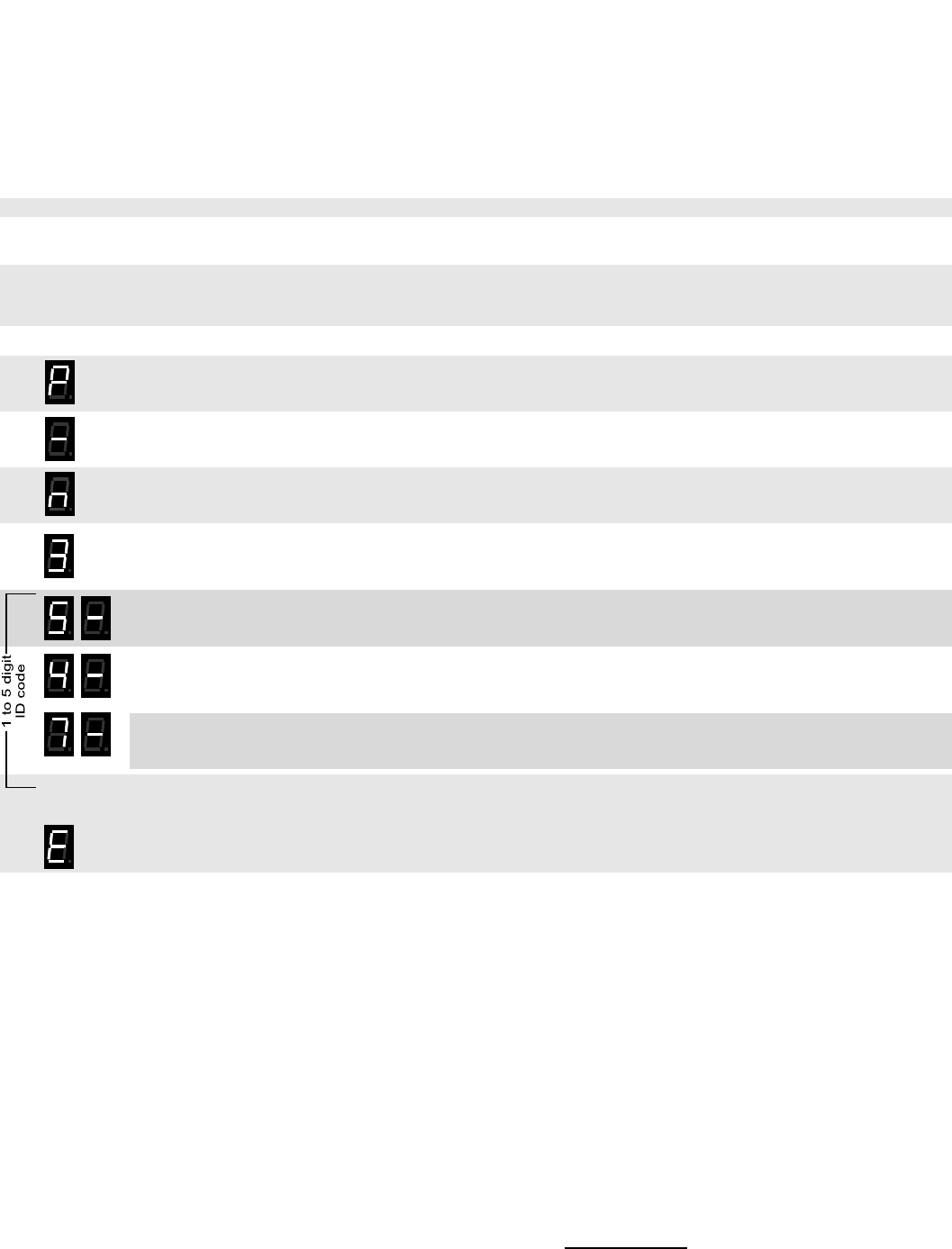
RQX XD-Series Wireless Callbox GateGuard® Application
Have questions? Call 800-USA-1-USA (800-872-1872) or visit our website at www.ritron.com 36
H
OW TO
F
IELD
P
ROGRAM AN
NXDN
UNIT
’
S
SUID
CODE
..........................
Each Callbox can be uniquely identified by programming an NXDN SUID. The user is able to field program the radio for any 1-5 digit
ID (1 to 65519). The radio will transmit the ID code in each transmission. In our example we will program an RQXD to operate with
an SUID Code of “547”.
1. Write down the desired SUID.
2. Loosen the (4) captive screws in the front corners of the case. These screws are captive to the housing; to
prevent damaging them, DO NOT remove the screws from the housing.
3. Separate the case front from the case back, leaving the batteries connected to the radio. Make sure the
unit has batteries installed.
NOTE: The voltage of the batteries must be greater than 3.3 VDC to program properly.
4. Press and release the ON/PTT button on the front of the unit to turn the radio on.
5. Press and HOLD the Program Button (See FIG-2 on page 7 for location). A "P" will appear on the program
display as you enter program mode and the radio will beep rapidly.
6. Release the program button after the beeping has stopped. The radio will emit a triple beep indicating that
the radio is in program mode and a hyphen will appear on the program display.
7. Click the Program button until the program display shows the Program Code “n”. Pause—the radio will
sound a low tone and show a hyphen across the center of the display to indicate that it is ready to accept a
1 to 5-digit SUID.
8. Click the Program button until the program display shows the Program Code “3”. Pause—the radio will
sound a low tone and show a hyphen across the center of the display to indicate that it is ready to accept a
1 to 5-digit SUID.
9. Enter the 1st digit of the SUID code by clicking the Program button until the program display shows the
desired number. Pause—the radio will sound a low tone and show a hyphen across the center of the
display to indicate that it is ready to accept the next digit.
10. Enter the 2nd digit of the SUID code by clicking the Program button until the program display shows the
desired number. Pause—the radio sounds a low tone and will show a hyphen across the center of the
display to indicate that it is ready to accept the next digit.
11. Enter the 3rd digit of the SUID sequence by clicking the Program button until the program display shows the
desired number. Pause—the radio sounds a low tone and will show a hyphen across the center of the
display to indicate that it is ready to accept the next digit. Continue entering up to seven digits.
12. Press and release the ON/PTT button to save your programming. A triple beep will sound to indicate that
programming was successful and a hyphen will appear on the program display. The radio is now ready for
another program entry.
NOTE: An error tone will sound if you attempt to save an incorrect code, an "E" will appear on the display.
Check the digits you are attempting to enter, then re-enter.
13. Once you have made your final program entry, press the ON/PTT button a final time to turn the radio off.
Turn the radio back on for normal operation.
Other RAN and ID codes from table 8 can be programmed as seen in the above example (see table 8).
547

RQX XD-Series Wireless Callbox Licensing
Have questions? Call 800-USA-1-USA (800-872-1872) or visit our website at www.ritron.com 37
FCC Licensing
Except for the five (5) MURS frequencies listed on page 12, the FCC requires the owners of radios operating on these frequencies to obtain a
station license before using them.
The station licensee is responsible for ensuring that transmitter power, frequency and deviation are within the limits specified by the station license.
The station licensee is also responsible for proper operation and maintenance of the radio equipment. This includes checking the transmitter
frequency and deviation periodically, using appropriate methods.
To get an FCC license for VHF or UHF frequencies, submit FCC application Form 601. Your Ritron dealer can help you with this process.
How to Obtain an FCC Radio License
Because your Ritron radio operates on Private Land Mobile frequencies, it is subject to the Rules and Regulations of the FCC, which requires all
operators of these frequencies to obtain a station license before operating their equipment. Make application for your FCC license on FCC Forms
601, Schedules D and H, and Fee Remittance Form 159.
To have forms and instructions faxed to you by the FCC, call the FCC Fax-On-Demand system at 202-418-0177 from your fax machine; request
Document numbers 3000159, 3060001, 3060003, and 3060006.
To have Document numbers 3000159, 3060001, 3060003, and 3060006 mailed to you, call the FCC Forms Hotline at 800-418-FORM (800-418-
3676).
For help with questions concerning the license application, contact the FCC at 888-CALL-FCC (888-225-5322) or log on at www.fcc.gov
You must decide which radio frequency(ies) you can operate on before filling out your application.
For help determining your frequencies, call Ritron at 800-USA-1-USA (800-872-1872).
INDUSTRY CANADA Regulations
Industry Canada requires the owners of the radios to obtain a radio license before using them.
Application forms can be obtained from the nearest Industry Canada District office.
1. Fill in the items per the instructions. If you need additional space for any item, use the reverse side of the application.
2. Use a typewriter or print legibly.
3. Make a copy for your files.
4. Prepare a check or money order to “Receiver General for Canada”, for the amount listed at http://www.ic.gc.ca/eic/site/smt-
gst.nsf/eng/sf01027.html. (Licenses are renewed annually on April 1st. Refer to the calculation for application fees for each month.)
5. Mail the completed application, along with your check or money order, to the closest Industry Canada District Office.
Notes: Fees are subject to change without notice.
Safety Standards
The FCC (with its action in General Docket 79-144, March 13, 1985) has adopted a safety standard for human exposure to radio frequency
electromagnetic energy emitted by FCC regulated equipment. Ritron observes these guidelines and recommends that you do also:
• DO NOT hold the radio so that the antenna is very close to or touching exposed parts of the body, especially the face or eyes, while
transmitting. Keep the radio vertical, eight inches away while talking into the front panel.
• DO NOT press the Push-To-Talk except when you intend to transmit.
• DO NOT operate radio equipment near electrical blasting caps or in an explosive atmosphere.
• DO NOT allow children to play with any radio equipment that contains a transmitting device.
• Repair of Ritron products should be performed only by Ritron authorized personnel.
Service
Federal law prohibits you from making any internal adjustments to the transmitter, and / or from changing transmit frequencies unless you are
specifically designated by the licensee.
If your radio equipment fails to operate properly, or you wish to have the radio programmed, contact your local authorized dealer or Ritron.
U.S. Manufacturer:
RITRON, INC. - Repair Department
505 West Carmel Drive,
Carmel, Indiana 46032 USA
Phone: 317-846-1201
FAX: 317-846-4978
Email: customer_service@ritron.com

RQX XD-Series Wireless Callbox Warranty
Have questions? Call 800-USA-1-USA (800-872-1872) or visit our website at www.ritron.com 38
RITRON,
INC.
L
IMITED
W
ARRANTY
.......................................................
WHAT THIS WARRANTY COVERS:
RITRON, INC. ("RITRON") provides the following warranty against defects in materials and/or workmanship in RITRON Radios and Accessories
under normal use and service during the applicable warranty period (as stated below). "Accessories" means antennas, holsters, chargers, ear-
phones, speaker/microphones and items contained in the programming and programming/service kits.
WHAT IS COVERED FOR HOW LONG WHAT RITRON WILL DO
XD-Series Callbox 1 year* During the first year after date of purchase, RITRON will repair or
replace the defective product, at RITRON's option, parts and labor
included at no charge.
Accessories 90 days* *After date of purchase
WHAT THIS WARRANTY DOES NOT COVER:
• Any technical information provided with the covered product or any other RITRON products;
• Installation, maintenance or service of the product, unless this is covered by a separate written agreement with RITRON;
• Any products not furnished by RITRON which are attached or used with the covered product, or defects or damage from the use of the covered
product with equipment that is not covered (such as defects or damage from the charging or use of batteries other than with covered product);
• Defects or damage, including broken antennas, resulting from:
- misuse, abuse, improper maintenance, alteration, modification, neglect, accident or act of God,
- the use of covered products other than in normal and customary manner or,
- improper testing or installation;
• Defects or damages from unauthorized disassembly, repair or modification, or where unauthorized disassembly, repair or modification prevents
inspection and testing necessary to validate warranty claims;
• Defects or damages in which the serial number has been removed, altered or defaced.
• Batteries if any of the seals are not intact.
IMPORTANT: This warranty sets forth the full extent of RITRON’s express responsibilities regarding the covered products, and is given in lieu of all
other express warranties. What RITRON has agreed to do above is your sole and exclusive remedy. No person is authorized to make any other
warranty to you on behalf of RITRON. Warranties implied by state law, such as implied warranties of merchantability and fitness for a particular pur-
pose, are limited to the duration of this limited warranty as it applies to the covered product. Incidental and consequential damages are not recover-
able under this warranty (this includes loss of use or time, inconvenience, business interruption, commercial loss, lost profits or savings). Some
states do not allow the exclusion or limitation of incidental or consequential damages, or limitation on how long an implied warranty lasts, so the
above limitations or exclusions may not apply to you. Because each covered product system is unique, RITRON disclaims liability for range, cover-
age, or operation of the system as a whole under this warranty.
WHO IS COVERED BY THIS WARRANTY: This warranty is given only to the purchaser or lessee of covered products when acquired for use,
not resale. This warranty is not assignable or transferable.
HOW TO GET WARRANTY SERVICE: To receive warranty service, you must deliver or send the defective product, delivery costs and insur-
ance prepaid, within the applicable warranty period, to RITRON, INC., 505 West Carmel Drive, Carmel, Indiana 46032, Attention: Warranty De-
partment. Please point out the nature of the defect in as much detail as you can. You must retain your sales or lease receipt (or other written evi-
dence of the date of purchase) and deliver it along with the product. If RITRON chooses to repair or replace a defective product, RITRON may re-
place the product or any part or component with reconditioned product, parts or components. Replacements are covered for the balance of the orig-
inal applicable warranty period. All replaced covered products, parts or components become RITRON’s property.
RIGHTS TO SOFTWARE RETAINED : Title and all rights or licenses to patents, copyrights, trademarks and trade secrets in any RITRON
software contained in covered products are and shall remain in RITRON. RITRON nevertheless grants you a limited non-exclusive, transferable right
to use the RITRON software only in conjunction with covered products. No other license or right to the RITRON software is granted or permitted.
YOUR RIGHTS UNDER STATE LAW: This warranty gives you specific legal rights, and you may also have other rights which vary from state
to state.
WHERE THIS WARRANTY IS VALID: This warranty is valid only within the United States, the District of Columbia and Puerto Rico.