Riverbed Technology DTAGA Wireless Access Point User Manual rev
Riverbed Technology Inc. Wireless Access Point Users Manual rev
Users Manual_rev.pdf
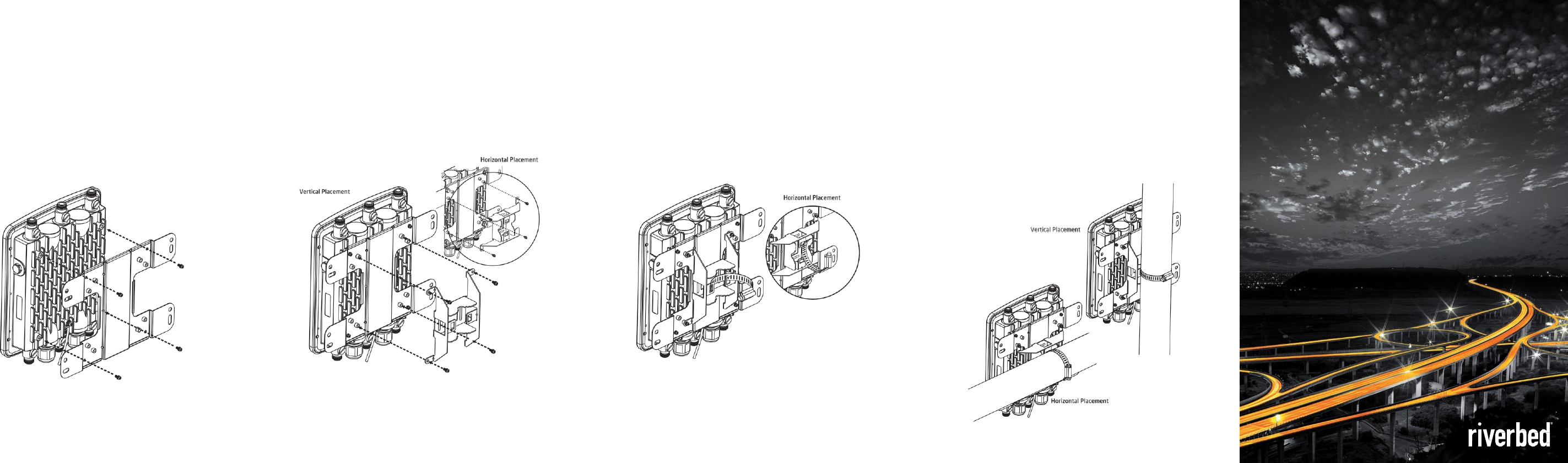
POLE MOUNTING THE AP5R
1.
Place the lock and flat washers on the four cap screws, and use the
screws to attach the bracket to the back of the Access Point.
2.
Determine placement (horizontal or vertical).
Use the four round head screws to attach the pole mount bracket .
3.
Thread the open end of the pole strap through the two tabs on the
pole mount bracket.
4. Lock and tighten the pole strap to secure the pole mount bracket
to the pole.
STEELCONNECT
TM
ACCESS POINT
LET’S GET STARTED…
30
mm
1.
POSITION THE DEVICE
You can mount the Access Point (AP) to a wall or a pole using the attached
mounting kit. Make sure to mount all antennas as indicated on the device
(2.4 GHz and 5 GHz). Refer to the instructions on the following pages.
2.
CONNECT THE POWER
The AP can only be powered by PoE+ (IEEE 802.3at) through the LAN1 port.
Supply power by connecting the LAN1 port either to a PoE+ injector or a PoE+
capable switch port.
3.
CONNECT TO THE NETWORK
Connect the AP to your local network. To find a SteelConnect Manager
instance, the AP needs Internet access; make sure the network provides a
DHCP service so the AP can establish a connection automatically.
4.
Pre-Install Preparation
You should complete the following steps before going on-site to perform an
installation.
4.1 Configure Your Network in SteelConnect Manager
Riverbed recommends that you add your AP to a network in Dashboard
before mounting it in the field. The following is a brief overview only of the
steps required to add an AP to your network. For detailed instructions about
creating, configuring and managing Riverbed wireless networks.
1. Login to
http://dodo.oceddo.cc
. If this is your first time, create a new account.
2. Find the network to which you plan to add your nodes or create a new network.
3. Add your nodes to your network. You will need the serial number of each node, which
looks like xxx-xxxx-xxxx, and is found on the bottom of the unit.
4.2 Assigning IP Addresses to AP
All gateway AP (AP with Ethernet connections to the LAN) must be assigned
routable IP addresses.
These IP addresses can be dynamically assigned via DHCP or statically assigned.
4.2.1 Dynamic Assignment
When using DHCP, the DHCP server should be configured to assign a static IP
address for each MAC address
belonging to a Riverbed AP. Other features of the wireless network, such as 802.1X
authentication, may rely on the property that the APs have static IP addresses.
4.2.2 Static Assignment
Static IPs are assigned using the local web server on each AP. The following
procedure describes how to set the static IP:
1. Using a client machine (e.g., a laptop), connect to the AP either wirelessly (by
associating to any SSID broadcast by the AP) or over a wired connection.
If using a wired connection, connect the client machine to the AP either through a
PoE switch.
2. Using a web browser on the client machine, access the AP’s built-in web server
by browsing to
http://dodo.oceddo.cc
3. Click on the “Static IP Configuration” tab.Configure the static IP address, net
mask, gateway IP address and DNS servers that this AP will use on its wired
connection.
5. If necessary, reconnect the AP to the LAN.
Need help?
Riverbed Technology | 680 Folsom Street | San Francisco, CA
94107
support@riverbed.com | (415) 247-7381 |
www.riverbed.com
WEEE-Reg.-Nr. DE 36272080
For more information, go to the Riverbed Support
website:
https://support.riverbed.com
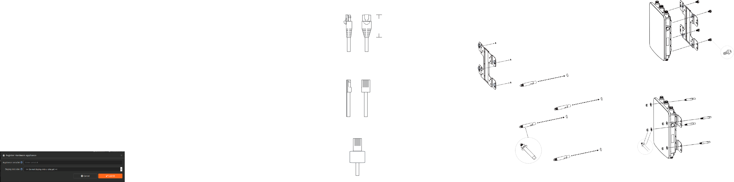
CONNECTOR REQUIREMENTS
Use CAT5e or higher connectors only.
Make sure the total plug length is 30mm or less.
Remove the bend protection and the catch protection with a cutter
if
needed. We also suggest removing the catch completely for easy
maintenance.
Place the sleeve around the cable and plug the connector into the
Access
Point. Make sure to pull the screw cap tight.
WALL MOUNTING THE AP5r
1.
Mark the four locations of the mounting holes on a flat mounting
surface.
2.
Drill holes in the four marked locations. Each hole should be 37 mm
(1.46 inch) deep and 8 mm (.31 inch) wide. Hammer the bolts into
the openings.
3. Place the lock and flat washers on the four cap screws, and use
the
screws to attach the bracket to the back of the Access Point.
4. Attach the device to the wall by tightening the bolt’s flat washers
and
nuts to secure the bracket to the mounting surface.

POE RATING
PoE+ Input: 48 VDC, 0.8 A
PSE Output: 54 VDC, 0.3 A
GROUNDING STRAP
Connect one end of the grounding strap to grounding post with included
screw and washer. Securely attach it to another nearby metal structure.
For equipment intended for installation in a Restricted Access Location,
this product can only be accessed by service person.
RESTRICTED ACCESS LOCATION
For equipment intended for installation in a Restricted Access Location,
the temperature limit in Table 4C of IEC 60950-1 applies, except for
external metal parts that are designed as heatsinks or that have a visible
warning, a temperature of 90°C/194°F is permitted.
WARNING
HOT
SURFACE DO
NOT TOUCH
TEMPERATURE RANGES
Operating temperature: -20°C - 70°C | 68°F - 158°F
Storage temperature: -30°C - 80°C | 22°F - 176°F
Federal Communication Commission Interference Statement
This equipment has been tested and found to comply with the limits for a
Class B digital device, pursuant to Part 15 of the FCC Rules. These limits
are designed to provide reasonable protection against harmful interference
in a residential installation. This equipment generates, uses and can
radiate radio frequency energy and, if not installed and used in accordance
with the instructions, may cause harmful interference to radio
communications. However, there is no guarantee that interference will not
occur in a particular installation. If this equipment does cause harmful
interference to radio or television reception, which can be determined by
turning the equipment off and on, the user is encouraged to try to correct
the interference by one of the following measures:
-Reorient or relocate the receiving antenna.
-Increase the separation between the equipment and receiver.
-Connect the equipment into an outlet on a circuit different from
that
to which the receiver is connected.
-Consult the dealer or an experienced radio/TV technician for
help.
FCC Caution: Any changes or modifications not expressly approved by the
party responsible for compliance could void the user's authority to operate
this equipment.
This device complies with Part 15 of the FCC Rules. Operation is subject
to the following two conditions: (1) This device may not cause harmful
interference, and (2) this device must accept any interference received,
including interference that may cause undesired operation.
This transmitter must not be co-located or operating in conjunction with
any other antenna or transmitter.
IMPORTANT NOTE:
FCC Radiation Exposure Statement:
This equipment complies with FCC radiation exposure limits set forth for
an uncontrolled environment. This equipment should be installed and
operated with minimum distance 32cm between the radiator & your body.
Industry Canada statement:
This device complies with ISED’s licence-exempt RSSs. Operation is
subject to the following two conditions: (1) This device may not cause
harmful interference, and (2) this device must accept any interference
received, including interference that may cause undesired operation.
Le présent appareil est conforme aux CNR d’ ISED applicables aux
appareils radio exempts de licence. L’exploitation est autorisée aux deux
conditions suivantes : (1) le dispositif ne doit pas produire de brouillage
préjudiciable, et (2) ce dispositif doit accepter tout brouillage reçu, y
compris un brouillage susceptible de provoquer un fonctionnement
indésirable.
Caution :
(i) the device for operation in the band 5150-5250 MHz is only for indoor
use to reduce the potential for harmful interference to co-channel mobile
satellite systems;
(ii) the maximum antenna gain permitted for devices in the band 5725-
5850 MHz shall be such that the equipment still complies with the e.i.r.p.
limits specified for point-to-point and non-point-to-point operation as
appropriate; and
(iii) Users should also be advised that high-power radars are allocated as
primary users (i.e. priority users) of the bands 5650-5850 MHz and that
these radars could cause interference and/or damage to LE-LAN devices.
Avertissement:
(i) les dispositifs fonctionnant dans la bande 5150-5250 MHz sont
réservés uniquement pour une utilisation à l’intérieur afin de réduire les
risques de brouillage préjudiciable aux systèmes de satellites mobiles
utilisant les mêmes canaux;
(ii) le gain maximal d'antenne permis (pour les dispositifs utilisant la
bande de 5725 à 5 850 MHz) doit être conforme à la limite de la p.i.r.e.
spécifiée pour l'exploitation point à point et l’exploitation non point à point,
selon le cas;
(iii) De plus, les utilisateurs devraient aussi être avisés que les utilisateurs
de radars de haute puissance sont désignés utilisateurs principaux (c.-à-
d., qu’ils ont la priorité) pour les bandes 5650-5850 MHz et que ces
radars pourraient causer du brouillage et/ou des dommages aux
dispositifs LAN-EL.
Radiation Exposure Statement:
This equipment complies with ISED radiation exposure limits set forth for
an uncontrolled environment. This equipment should be installed and
operated with minimum distance 37cm between the radiator & your body.
Déclaration d'exposition aux radiations:
Cet équipement est conforme aux limites d'exposition aux rayonnements
ISED établies pour un environnement non contrôlé. Cet équipement doit
être installé et utilisé avec un minimum de 37 cm de distance entre la
source de rayonnement et votre corps.
Professional installation instruction
1. Installation personal
This product is designed for specific application and needs to be
installed by a qualified personal who has RF and related rule
knowledge. The general user shall not attempt to install or
change the setting.
2. Installation location
The product shall be installed at a location where the radiating
antenna can be kept 32cm (for FCC) / 37cm (for IC) from nearby
person in normal operation condition to meet regulatory RF
exposure requirement.
3. External antenna
Use only the antennas which have been approved by the
applicant. The non-approved antenna(s) may produce
unwanted spurious or excessive RF transmitting power which
may lead to the violation of FCC/IC limit and is prohibited.
4. Installation procedure
Please refer to user’s manual for the detail.
5. Warning
Please carefully select the installation position and make sure
that the final output power does not exceed the limit set force in
relevant rules. The violation of the rule could lead to serious
federal penalty.
Instructions d'installation professionnelle
1. Installation
Ce produit est destine a un usage specifique et doit etre installe par un
personnel qualifie maitrisant les radiofrequences et les regles s'y
rapportant. L'installation et les reglages ne doivent pas etre modifies par
l'utilisateur final.
2. Emplacement d'installation
En usage normal, afin de respecter les exigences reglementaires
concernant l'exposition aux radiofrequences, ce produit doit etre installe
de facon a respecter une distance de 37cm entre l'antenne emettrice et
les personnes.
3. Antenn externe.
Utiliser uniiquement les antennes approuvees par le fabricant. L'utilisation
d'autres antennes peut conduire a un niveau de rayonnement essentiel
ou non essentiel depassant les niveaux limites definis par IC, ce qui est
interdit.
4. Procedure d'installation
Consulter le manuel d'utilisation.
5. Avertissement
Choisir avec soin la position d'installation et s'assurer que la puissance de
sortie ne depasse pas les limites en vigueur. La violation de cette regle
peut conduire a de serieuses penalites federales.