Roadmaster 9510 Supplemental Brake Monitoring System. RV Monitor. User Manual 16 3099 Manual
Roadmaster, Inc. Supplemental Brake Monitoring System. RV Monitor. 16 3099 Manual
Manual

2320 Presidential Drive, Suite 101, Durham, NC 27703 USA Voice: 919-381-4235
Certification Exhibit
FCC ID: RGY-9510
IC: 22290-9510
FCC Rule Part: 15.247
ISED Canada’s Radio Standards Specification: RSS-247
ACS Project Number: 16-3099
Manufacturer: Roadmaster Inc.
Model: EA066-M
Manual

FCC Compliance Statement
Warning:ChangesormodicationstothesedevicesnotexpresslyapprovedbyRoadmaster,Inc.couldvoidtheuser’sauthor-
itytooperatetheequipment.
NOTE:ThisequipmenthasbeentestedandfoundtocomplywiththelimitsforaClassBdigitaldevice,pursuanttoPart15
oftheFCCRules.Theselimitsaredesignedtoprovidereasonableprotectionagainstharmfulinterferenceinaresidentialinstal-
lation.Thisequipmentgenerates,uses,andcanradiateradiofrequencyenergyand,ifnotinstalledandusedinaccordancewith
theinstructions,maycauseharmfulinterferencetoradiocommunications.However,thereisnoguaranteethatinterferencewill
notoccurinaparticularinstallation.Ifthisequipmentdoescauseharmfulinterferencetoradioortelevisionreception,which
canbedeterminedbyturningtheequipmentoffandon,theuserisencouragedtotrytocorrecttheinterferencebyoneormore
ofthefollowingmeasures:
• Reorientorrelocatethereceivingantenna.
• Increasetheseparationbetweentheequipmentandreceiver.
• Connecttheequipmentintoanoutletonacircuitdifferentfromthattowhichthereceiverisconnected.
• Consultthedealeroranexperiencedradio/TVtechnicianforhelp.
FCCID:RGY-9510
IC:22290-9510
FCCID:RGY-9520
IC:22290-9520
THESEDEVICESCOMPLYWITHPART15OFTHEFCCRULES.OPERATIONISSUBJECTTOTHEFOLLOWING
TWOCONDITIONS.
(1)THESEDEVICESMAYNOTCAUSEHARMFULINTERFERENCE,AND(2)THESEDEVICESMUSTACCEPT
ANYINTERFERENCERECEIVED,INCLUDINGINTERFERENCETHATMAYCAUSEUNDESIREDOPERATION.
FCCRadioFrequencyExposure
Thisequipmentcomplieswithradiationexposurelimitssetforthforanuncontrolledenvironment.Thisequipmentshouldbe
installedandoperatedwithminimumdistance20cmbetweentheradiatorandyourbody.Thistransmittermustnotbeco-locatedor
operatinginconjunctionwithanyotherantennaortransmitter.
Cetéquipementestconformeauxlimitesd’expositionauxradiationsdansunenvironnementnoncontrôlé.Cetéquipementdoitêtre
installéetutiliséàdistanceminimumde20cmentreleradiateuretvotrecorps.Cetémetteurnedoitpasêtreco-localiséesouopérant
enconjonctionavectoutautreantenneoutransmetteur.
IndustryCanadaLicenseExempt
ThisdevicecomplieswithIndustryCanadalicense-exemptRSSstandard(s).Operationissubjecttothefollowingtwoconditions:
(1)thisdevicemaynotcauseinterference,and(2)thisdevicemustacceptanyinterference,includinginterferencethatmaycause
undesiredoperationofthedevice.
LeprésentappareilestconformeauxCNRd’IndustrieCanadaapplicablesauxappareilsradioexemptsdelicence.L’exploitation
estautoriséeauxdeuxconditionssuivantes:(1)l’appareilnedoitpasproduiredebrouillage,et(2)l’utilisateurdel’appareildoitac-
ceptertoutbrouillageradioélectriquesubi,mêmesilebrouillageestsusceptibled’encompromettrelefonctionnement.
All illustrations and specifications contained in this document are based on the latest information available at the time of
publication. ROADMASTER, Inc. reserves the right to make changes at any time, without notice, in material, specifications
and models, or to discontinue models.
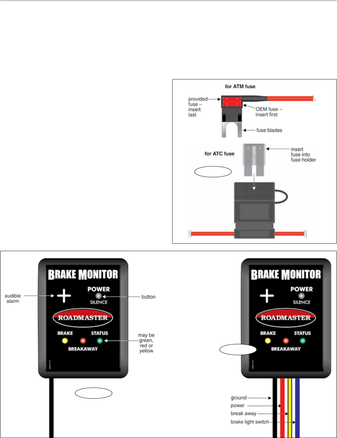
Figure C
Installation and operation
Figure A
Installation
Note: the most noticeable difference between the mo-
torhome monitor (Figure A) and the towed vehicle trans-
mitter (Figure B) are the wires extending from them. The
transmitter has four colored wires; the monitor has one
black wire.
1. Choose a suitable installation point for the towed ve-
hicle transmitter under the dashboard. Since the transmit-
ter doesn’t have to be accessed once it’s installed, any
mounting point that doesn’t present an obstacle to the
driver, or interfere with the operation of the vehicle, is
suitable.
2. Attach the wires. (If necessary, use one of the included
butt connectors and 18-gauge wire to extend the wiring.)
• Attach the black wire to any good chassis ground.
• Attach the red wire to any 12V+ source. Depending on
the size of the fuse, use the ATM or the ATC fuse holder
(Figure C).
• Attach the yellow wire to the wire on the break away
switch which will be energized during a break away.
• Attach the blue wire to the cold (‘switched’) side of
the brake light switch.
3. Use the included Velcro strips to attach the transmitter.
4. Plug the motorhome monitor into any 12V+ source in
the motorhome, and attach it with the Velcro strips at any
location where it can be seen by the driver.
Operating the monitor
1. Check the “Status” light:
• If the light is solid green you’re ready to tow.
• If the light is alternately flashing red and green, it’s not
receiving a signal. Pump the towed vehicle’s brake pedal —
the light should now be solid green.
2. To turn the monitor off, press the “Power” button. (The
monitor will always turn off after a few minutes when the
motorhome’s engine is turned off.)
How to pair the monitor and transmitter
The motorhome monitor and the towed vehicle transmit-
ter have been paired at the factory. If they’ve lost connectiv-
continued on next page
Figure B

Comprehensive list of monitor messages
• The “Status” light is solid green.
The system is ready for towing.
• The “Status light is flashing red and green.
The monitor isn’t receiving a signal from the towed vehi-
cle. Pump the towed vehicle’s brake pedal — the light should
now be solid green.
• The “Status” light is off.
The monitor “Power” switch has been turned off, or the
monitor has powered down.
• The “Status” light is yellow.
The towed vehicle’s battery is low.
• The “Status” light is flashing bright red; the “Brake”
light is flashing yellow; accompanied with an audible
alarm.
The towed vehicle’s brakes have been on continuously
for 30 seconds. Pump the motorhome brakes to reset the 30
second timer.
Alternatively, press the “Silence” button once — the timer
will now alarm only after 60 seconds of continuous braking.
If the “Silence” button is pressed again after the alarm at 60
seconds, it will reset the timer to only alarm after 90 sec-
onds. This can be extended once more to 120 seconds.
Caution
If the monitor alerts you to extended braking when you
are not braking the motorhome, the brakes in the towed
Motorhome monitor color code chart
Status Brake Breakaway
Light Light Light Color Description
• Solid green .......................... The system is ready for towing.
•• flashing red and green ........ The monitor isn’t receiving a signal from the transmitter.
• “Status” light is off ............... The “Power” switch has been turned off.
• yellow .................................. The towed vehicle’s battery is low.
• • flashing red and yellow ....... Extended braking alert
♪(includes an audio alert)
• • solid red and flashing red ... A break away is in progress.
♪(includes an audio alert)
• solid yellow .......................... The towed vehicle’s brakes are being applied.
continued from preceding page
ity pair them as follows:
1. Power on the motorhome monitor.
2. Depress and hold the “Power” button on the motorhome
monitor for about five seconds. The “Status” light will flicker
yellow.
3. Release the “Power” button. The “Status” light on both
the towed vehicle transmitter and the motorhome monitor
will start flashing yellow. The units are now in pairing mode.
4. Depress and release the brake pedal in the towed vehi-
cle. The lights will stop flashing. The transmitter and monitor
are paired.
Monitor alerts
vehicle are being applied inappropriately. Immediately
pull over and investigate to prevent brake damage.
• The “Status” light is flashing bright red; the “Break
away” light is solid red; accompanied with an audible
alarm.
The monitor is reporting a break away signal from the
towed vehicle. Pull over as soon as it is safe to do so and
investigate.
• The “Brake” light is yellow.
The “Brake” light will illuminate yellow whenever the
towed car’s brakes are on.