Robert Bosch Tool F034K69P01 Wireless Hand Controller User Manual RL200 GR and RL300
Robert Bosch Tool Corporation Wireless Hand Controller RL200 GR and RL300
User Manual
LMPL20
LMPL20
LMPL20
m
SEL
00.000
6
+
LMPL20 Pipe Laser
Model
59-LMPL20
INSTRUCTION MANUAL
Electronic Self-Leveling

2 • LMPL20
LMPL20 • 3
Fig. 1
Fig. 2
Fig. 3
LMPL20LMPL20LMPL20
m
SEL
Lock
Line control
/
A
B
00.000
6
+F
D2
C
D1 E2
E1
2
3
4
58
LMPL20
LMPL20LMPL20
m
SEL
10
2
1
3
4
5 6 7
9
8
10
00.000
6
+
4 • LMPL20
XY
* * *
ABC...
XY
* * *
00.000
6
+
PHONE
ABCDEFG IHJKL
NAME
A
CI Y STATE
DDRESS
a
b
c
d
e
f
g
T
XXXXXXXXXXXX
Fig. 4
Fig. 5
Fig. 6
Fig. 8
Fig. 7
Fig. 9
Fig. 10
X=353
510
10 234567 98
****
000
9
Fig. 11
CHANGE
RESET
SECURITY
CHANGE
RESET
SECURITY Fig. 12
XY
* * *
ABC...
XY
* * *
GRADE UNITS
Fig. 13
XY
* * *
ABC...
XY
* * *
SECURITY
Fig. 14
LMPL20 • 5
A
E
D
B
F
D
E
C
RC20
Fig. 15
Remote
a
b
c
d
Fig. 18
Fig. 19
00.000
+
00.000
+a
b
Fig. 16
Fig. 17
Fig. 20
Fig. 21
Fig. 22
000
9
Thank you for purchasing the CST/Berger LMPL20 Electronic Self-Leveling Pipe Laser level.
The LMPL20 pipe laser tool has many unique features such as a High Powered Red laser
beam, which makes accurately locating the center of the beam easy. The Unique High
Powered Red Laser beam also increases the visibility of the laser over long distances-
inside or outside the pipe.
Note: Please read this manual thoroughly before operation
MODEL
59-LMPL20 Pipe Laser, 12 VDC Ext. Power Cable, NiMH Battery Charger, NiMH Battery Pack, Alkaline
Battery Pack, Small Target, Large Target, Target Holder, Carrying Case, Leg Set,
Remote Control RC20, Instruction Manual, Warranty Card.
Copyright © 2009 Robert Bosch Tool Corporation, All rights reserved.
The information contained herein is proprietary information of Robert Bosch Tool Corporation and is subject to
change without notice.
This document shall not be copied or otherwise reproduced without Robert Bosch Tool Corporation’s
written consent.
SAFE OPERATING PROCEDURES
CAUTION: Use of controls or adjustments or performance of procedures other than those specified herein
may result in hazardous radiation exposure
WARNING: Be sure to read and understand all instructions in this manual before using this product.
Failure to follow all instructions may result in hazardous radiation exposure, electric shock, fire, and/or
bodily injury.
CAUTION: Use of controls or adjustments or performance of procedures other than those specified in this
manual, may result in hazardous radiation exposure.
CAUTION: The use of optical instruments with this product will increase eye hazard.
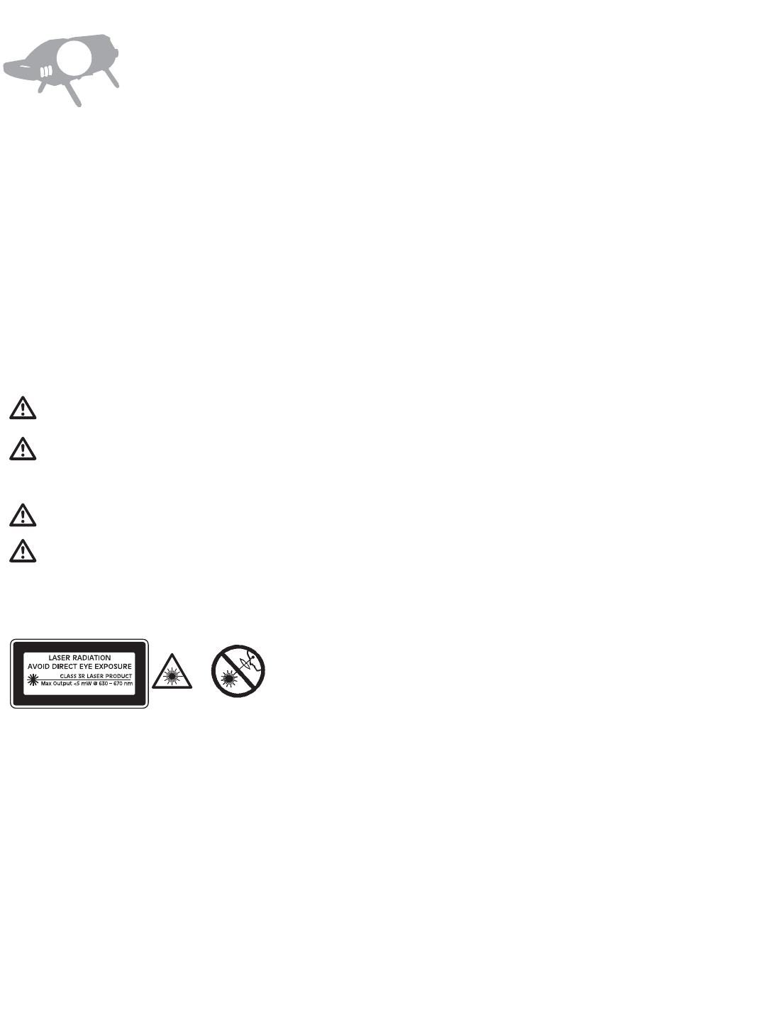
IMPORTANT: The following labels are on your LMPL20 for your convenience and safety. They indicate where
the laser light is emitted by the level. ALWAYS BE AWARE of their location when using the level.
ALWAYS make sure that any bystanders in the vicinity of use are made aware of the dangers of looking directly
into the pipe laser tool .
DO NOT remove or deface any warning or caution labels. Removing labels increases the risk of exposure to
laser radiation.
DO NOT stare directly at the laser beam or project the laser beam directly into the eyes of others. Serious eye
injury could result.
DO NOT place the pipe laser tool in a position that may cause anyone to stare into the laser beam intentionally
or unintentionally. Serious eye injury could result.
DO NOT use any optical instruments such as, but not limited to, telescopes or transits to view the laser beam.
Serious eye injury could result.
ALWAYS remove the batteries when cleaning the laser light aperture or laser lens.
DO NOT operate the pipe laser tool around children or allow children to operate the pipe laser tool . Serious
eye injury could result.
ALWAYS turn the pipe laser tool "OFF" when not in use. Leaving the pipe laser tool "ON" increases the risk of
someone inadvertently staring into the laser beam.
EN
6 • LMPL20
ACCORDING TO IEC/EN 60825-1: 2007
DO NOT operate the pipe laser tool in combustible areas such as in the presence of flammable liquids, gases or dust.
ALWAYS position the pipe laser tool securely. Damage to the pipe laser tool and/or serious injury to the user
could result if the pipe laser tool falls.
ALWAYS use only the accessories that are recommended by the manufacturer of your pipe laser tool . Use of
accessories that have been designed for use with other pipe laser tool s could result in serious injury.
DO NOT use this pipe laser tool for any purpose other than those outlined in this manual. This could result in
serious injury.
DO NOT leave pipe laser tool "ON" unattended in any operating mode.
ALWAYS repair and servicing must be performed by a qualified repair facility. Repairs performed by unqualified
personnel could result in serious injury.
DO NOT disassemble the pipe laser tool . There are no user serviceable parts inside. Disassembling the laser
will void all warranties on the product. Do not modify the product in any way. Modifying the pipe laser tool
may result in hazardous laser radiation exposure.
ELECTRICAL SAFETY PROCEDURES
WARNING: Batteries can explode or leak, and can cause injury or fire. To reduce this risk:
ALWAYS follow all instructions and warnings on the battery label and package.
DO NOT short any battery terminals.
DO NOT charge alkaline batteries.
DO NOT mix old and new batteries. Replace all of them at the same time with new batteries of the same brand
and type.
DO NOT mix battery chemistries.
DISPOSE of batteries per local code.
DO NOT dispose of batteries in fire.
KEEP batteries out of reach of children.
REMOVE batteries if the device will not be used for several months.
CERTIFICATIONS
This laser complies with all applicable portions of title 21 of the Code of Federal Regulations set by the Food and
Drug Administrations, Center for Devices, and Radiological Health. Complies with 21CFR 1040.10 and 10040.11
except for deviations pursuant to Laser notice No. 50, dated June 24, 2007.
This LMPL20 has also been tested and complies with the CE certification requirements set forth in the EC
regulations 89/336/EEC and EN 61000-6-1 (EN50082-1), EN 61000-6-3 (EN50081-1) and EN 60825-1.
LMPL20
RC20
ENVIRONMENT PROTECTION
Recycle raw materials & batteries instead of disposing of waste. The unit, accessories, packaging &
used batteries should be sorted for environmentally friendly recycling in accordance with the your
countries latest regulations.
LMPL20 • 7
Contains FCC ID: MCQ-XBEEPRO2
The enclosed device complies with Part 15 of the FCC Rules. Operation is subject to the following two conditions: (i.) this device may not cause
harmful interference and (ii.) this device must accept any interference received, including interference that may cause undesired operation.
Contains Model XBee-PRO Radio, IC: 1846A-XBEEPRO2
ID: 005NYCA0378
Contains FCC ID: TXT - F034K69P01
The enclosed device complies with Part 15 of the FCC Rules. Operation is subject to the following two conditions: (i.) this device may not cause
harmful interference and (ii.) this device must accept any interference received, including interference that may cause undesired operation.
Contains Model XBee-PRO Radio, IC: 909G-F034K69P01
ID: 005NYCA0378
8 • LMPL20
FEATURES
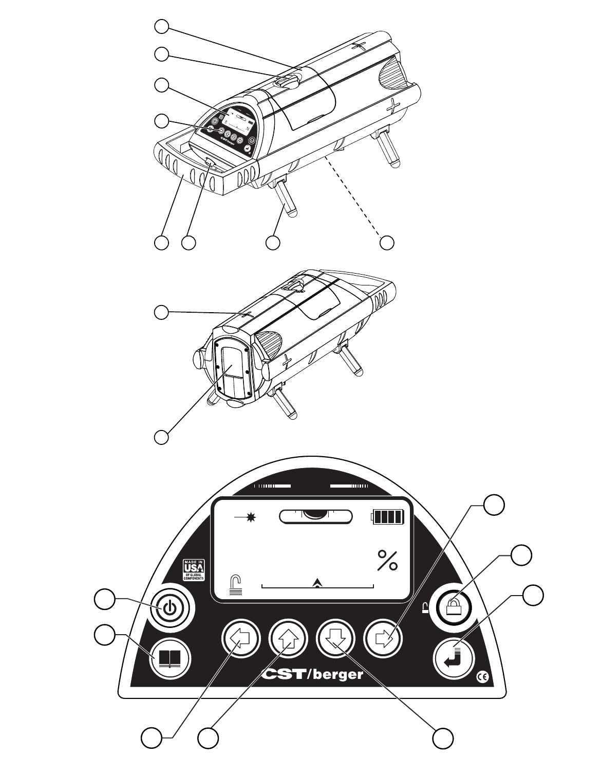
Fig. 1 & 2
1. Battery pack
2. Battery pack knob
3. LCD Display
4. Operating keys
5. Handle
6. External 12V Port
7. Interchangeable
legs
8. 5/8 -11 Tripod
mount
9. Laser centerline/
Plumb LED
10. Laser beam
window
OPERATION
Leveling
Place the LMPL20 so it is appears level on a flat surface, inside a pipe, on top of a pipe, secured to a 5/8”-11
mounting bracket, or to a 5/8”-11 surveyors tripod. Press and release the “A” button to turn the LMPL20 on. A
Startup Screen will initially appear on the LCD with manufacturer name and user information, if entered, for
approximately 3 second. If you press and hold the “A” button, the Startup Screen will remain on the LCD until
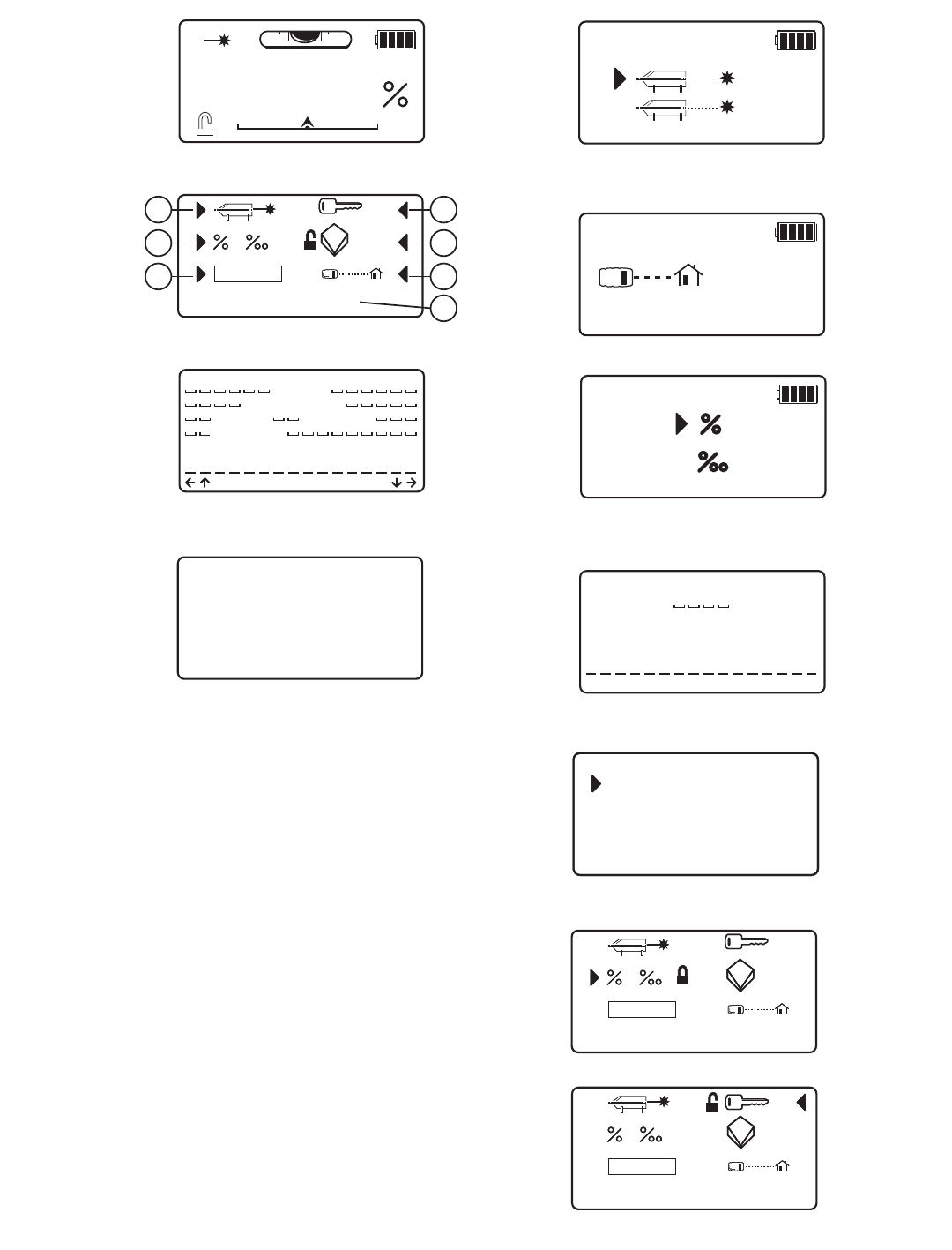
the button is released. The Main Screen will appear after the Startup Screen (Fig. 4 on Remote it is Fig. 16).
The Plumb LED turns on when the LMPL20 is turned on.
Allow the 60 seconds for the LMPL20 to self-level after entering the Main Screen. While the LMPL20 is leveling,
the laser will blink ON and OFF at a one second rate. Once the LMPL20 is level, the laser will turn on according
to the selected laser power mode. The LMPL20 will automatically re-level if it is moved from its level position.
The Level Bubble Icon on the main screen indicates when the cross-axis is level.
Note:The LMPL20 is remote capable with the RC20 remote.
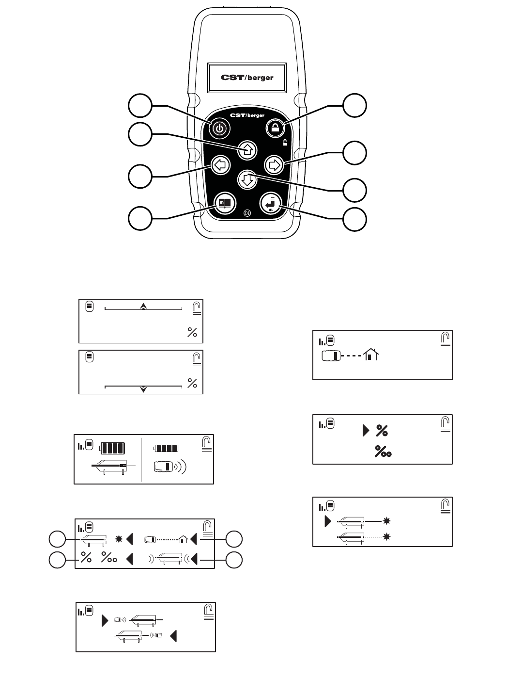
Note: Signal Strength is only displayed after receiving signals from the LMPL20.
REMOTE: The Main Screen of the Remote Control works in the same manner as the Main Screen of the
LMPL20, and has the same features displayed with the exception of.
Signal Strength - Display’s the Signal Strength level of the Remote Control
Sleep Mode- Conserves battery power by turning the LCD and laser beam off. When sleep mode is
turned off the LCD will re-aluminate and Laser beam will become visible again with out losing
previous settings.
Note: Sleep Mode function is only available using the remote.
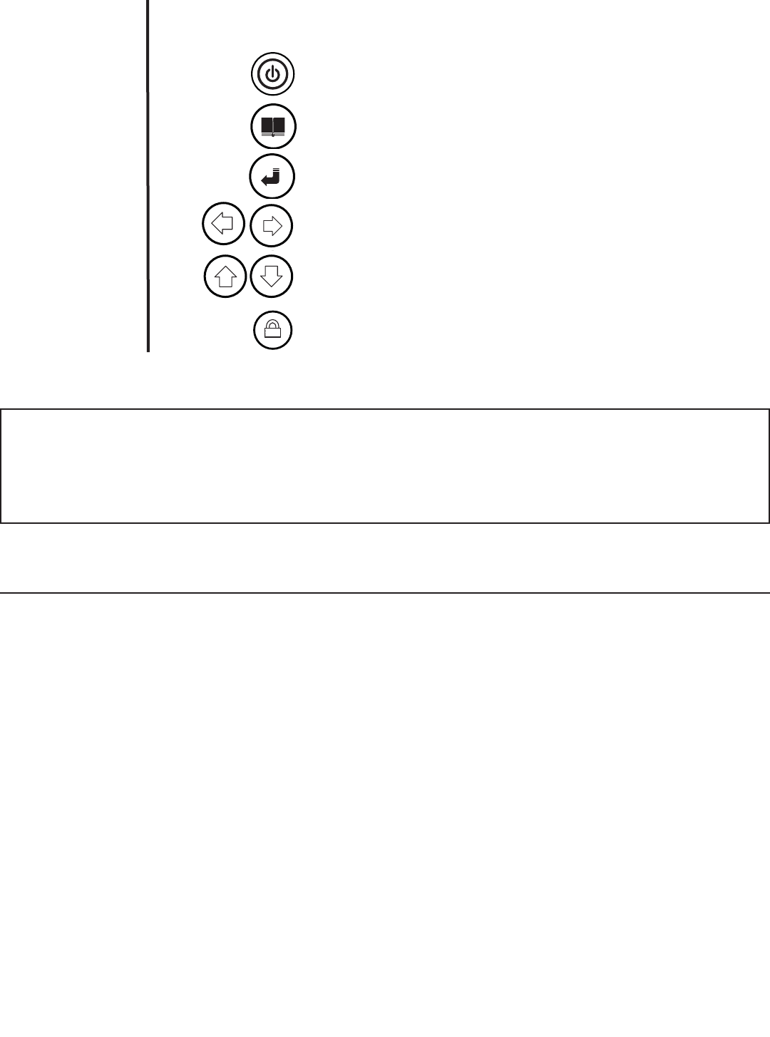
ICONS
Power key- Turn the instrument ON or OFF
(Remote: power button only powers on Remote and used to turn on
and off sleep mode)
Menu key- Press to show menu options.
Enter key- Press to set grade entries and to make selections from
menu screen.
Line control left and right- Press to position laser beam to left, right, or auto center.
Menu scroll key-
Used to scroll through menu options.
Grade up or down-
Press to position grade up or down, or auto zero grade
Menu scroll key-
Used to scroll through menu options.
Lock key- Press to prevent changes after setup.
A
B
C
D
E
F
Reference
in text
IMPORTANT
The owner/operator of the LMPL20 Pipe Laser is expected to follow all operation instructions, periodically
check the accuracy of the instrument, and make checks on line and grade as the work progresses. The
manufacturer, its distributors, or its agents assume no responsibility for improperly laid pipe.
m
SEL

Sleep Mode
Once the remote is on hold the power button for two seconds to select sleep mode. Then press the enter
button to activate sleep mode. Deactivate sleep mode using the same procedure, hold power button and then
press enter button.
Re-Leveling
If the LMPL20 is moved from its level position, the LMPL20 will re-level. The leveling feature of the laser is
independent of the Grade and Line Position Settings.
Plumb
1. On a flat horizontal surface place the LMPL20 in its normal operation position.
2. The LMPL20 has a Plumb LED located at the top of the LMPL20 (See Figure 2 #9). This led is
always on when the LMPL20 is powered on.
Grade
The Main Screen displays the selected grade. The LMPL20 has a grade range capability of +40% to –15%. A
grade setting of zero places the laser output at a level position. Grade can be entered in the following ways
from the Main Screen: (see Fig. 3)
1. Rolling Grade – either pressing the “E1” button or the “E2“ button directly enters grade. Pressing and
releasing either button will increment or decrement the grade setting by one. Press and holding either
button will gradually increase the speed at which the grade is incremented or decremented.
2. Direct Entry Grade – Pressing the “C” button will select Direct Entry Grade. Once the button is pressed,
the most significant grade number will be highlighted, indicating that the “E1” or “E2” button will either
increment or decrement the selected digit. Pressing the “D1” or “D2” button will allow selecting the
other grade digits. The selected grade will not take effect until either the “C” button is press again, or 5
seconds have passed without a button being pressed.
3. Auto Grade Zero – Pressing the “E1” and “E2” buttons at the same time implements this function. When
both buttons are pressed at the same time, the LMPL20 will go to a zero grade setting.
REMOTE: Grade can be entered in the same manner by using the RC20 Remote Control. (See Fig. 15)
Note: If the Lock has been turned on, Grade adjustments cannot be made.
Line Position
(See Fig. 3)
The LMPL20 ‘s laser line position can be adjusted ±15% from center. The Line Position can be adjusted from the
Main Screen by pressing the “D1” or the “D2” buttons. Pressing and releasing either button will make a small
adjustment. Pressing and holding either button will gradually increase the speed at which the line position is
adjusted. Pressing the “D1” or the “D2” buttons at the same time implements the Auto Line Position Function,
which positions the line position back to center. The Line Position Icon on the Main Screen indicates the
current position of the laser line. Press and hold both D1 and D2 buttons for three seconds to center the
line control.
REMOTE: Line Position can be entered in the same manner by using the RC20 Remote Control.
Note: When adjusting line position, the remote will communicate to the Pipe Laser with both RF and Infrared for buried
pipe applications.
Note: If the Lock has been turned on, Line Position adjustments cannot be made.
Lock
The Lock feature allows disabling grade and line position adjustments. Pressing the “F” button toggles the lock
between ON and OFF. The Lock Icon on the Main Screen indicates whether the Lock is ON or OFF.
LMPL20 • 9

10 • LMPL20
REMOTE: Lock can be turned ON or OFF in the same manner by using the RC20 Remote Control
Menu
The LMPL20 uses a menu based system for unit options and settings.
1. Select Menu Display Screen (Fig. 5) by pressing the “B” button.
2. Press “D” or “E” buttons to choose options.
3. Press “C” button to select a menu item.
The Menu Display Screen will appear on the LCD Display (See Figure 5). The Menu Display Screen lists the
following configuration setting options:
a. Laser Power Option– Used to adjust laser power and enable/disable fast blink mode.
b. Unit Option Screen – Used to select grade display in Percent or Percent Permilli.
c. Text Entry Screen – Used to set user information that is displayed on the Start Up Screen.
d. Security Option – Used to set a User Password and lock LMPL20 options.
e. XY Calibration Screen– Used to Electronically calibrate level for either the X or Y axis of the LMPL20.
f. Remote Communication Address Select Screen – Used to set LMPL20 address for use with remote.
g. Selected icon description (Language specific to the language set by your local dealer)
Note: An Arrow will indicate the current selected Menu Option. A Lock Icon will also display with the current
selected Menu Option which indicates whether the Menu Option is enabled or disabled. See the Security
Screen section.
REMOTE: The Menu screen of the Remote Control ( See Fig. 18 ) works in the same manner as the Main Screen
of the LMPL20, and has all the same features displayed including:
Remote Location Option (Front or rear operation)- Used to adjust Main Grade Display Screen with regard to working
point of view.
The Remote Control has an adjustable location display feature. This feature is used to set the Line Position
display on the Remote Control to match the working location of the user. The Line Position will display an arrow
indicator icon (see Figure 20) to display the current line position. Setting the Remote Location will match the
Line Position arrow so that it points in the same direction as the laser, regardless of the users working point
of view.
The Remote Location Option has two settings.
a. Behind Pipe Laser – The Remote Control display’s Line Position at the top of the Main Grade Display
Screen, with the arrow pointing in the direction of the laser (Pointed away from user).
b. In Front of Pipe Laser – The Remote Control display’s Line Position at the bottom of the Main Grade
Display Screen, with the arrow pointing in the direction of the laser (Pointed towards user). The Line
Position display will move in the opposite direction as the Behind Pipe Laser setting.
1. In the Menu Display Screen select Remote Location Option (Fig. 18 d) and press the “C” button.
2. The Remote Location Screen will appear in the LCD display.
3. Press the “E” buttons to select options.
4. Press the “B” to exit and save option
Line Alert
The LMPL20 Line Alert feature alerts the user that the laser line may have changed position (in line setting and
or elevation) if the pipe laser tool was disturbed.
When the pipe laser tool is turned on, it will default to the last setting selected for Line Alert. The default
setting for Line Alert is user selectable. The default setting may be set to Line Alert ON or Line Alert OFF. To
select the default setting for Line Alert, press the “B” button to select the Menu Display Screen. Pressing the
“B” button again within 3 seconds will display the Line Alert Screen. Pressing the “C” button will toggle

LMPL20 • 11
between Line Alert ON and Line Alert OFF. To return to the Main Display Screen, press the “B” button.
When Line Alert ON is selected, the Line Alert feature will become active after the pipe laser tool is level for 30
seconds. If the pipe laser tool is disturbed after 30 seconds, Line Alert will trigger. The pipe laser tool will stop
leveling and the laser beam will repetitively blink two times in one second with a one second pause before
blinking again. It is necessary to check any benchmarks that have been made to ensure the setup has not
changed. Pressing the “C” button will acknowledge the alert and return to the Main Display Screen and
normal operation.
Laser Power Screen
The Laser Power Screen allows the user to adjust the power out put to maximize laser visibility. The setting
range is from one through nine, and an optional pulse mode.
The Laser Power Screen (See Figure 8) has two options, below.
a. Laser Power – Increase/Decrease Laser Power
b. Fast Blink – Puts the laser in Full Power, but blinks the laser at a variable rate.
Note: Fast Blink does not blink at the same rate as the laser blinks during self-leveling.
1. Select Laser Power Option by pressing the “D” buttons.
2. Increase or decrease the value of the laser power by pressing the “E” buttons.
3. Once the Laser Power is selected, press the “B” to return to the Menu Display Screen
Unit Option Screen
The Unit Option Screen allows user to change from permil to percent units on the display screen. (Which moves
the decimal point on the grade display one position from Right to left.)
The Unit Option Screen (See Figure 10) has two options, below.
a. Percent – Displays Grade Value in Percent (Example: +10.000%)
b. Permil - Displays Grade Value in Permil (Example: +100.00‰)
1. Select Percent or Permil by pressing the “D” or “E” buttons.
2.. Press the “C” button to choose selected unit.
3. Once the unit is selected, press the “B” to return to the Menu Display Screen
Text Entry Screen
The LMPL20 offers the user the option to input up to four lines of text for displaying user information. This can
include, but is not limited to, the following:
a. Name
b. Address
c. Phone Number
Note: If the User has set up a password, then the LMPL20 will request the user enter a password before
entering the Text Entry Screen. If there is no set password, then the LMPL20 will enter the Text Entry
Screen directly.
On the Text Entry Screen (See Figure 6), the available text are located on the bottom of the screen. The top of
the screen displays the current User Information. The User Information is split across 4 rows, by 16 character
locations. If there is no User Information in a given character location, then it will display with an underscore
icon. Underscore icons are automatically replaced with blank spaces on the Start Up Screen.
1. Press the “D” buttons to select the desired character on the bottom of the Text Entry Screen
2. Only 12 characters can be displayed on the screen at one time. Press the “E” buttons to display the next
twelve characters.

3. Press the “C” button to enter the selected character into the current selected location on the top of the
screen. Selected location will automatically increment to the next location.
4. To select location of characters on the top side of the screen press the “D” button to choose the up,
down, left, and right arrows at the bottom of the screen.
5. Press the “C” button with left, right, up, or down arrows selected to move character location in
that direction.
6. The Underscore symbol will enter blank spaces.
7. Once all characters are set as desired press the “B” button to return to the Menu Display screen.
The LMPL20 will automatically save the text Entry in memory. The Text Entry will now display on the Start Up
Screen after first turning on the LMPL20.
Security Screen
(See Fig. 5)
The LMPL20 offers the user to enable or disable different functions in the Menu Display Screen.
1. In the Menu Display Screen select the Security Option (Fig. 14) and press the “C” button.
2. The Security Screen will appear in the LCD display (Fig. 12)
Note: If the User has previously set up a password, then the LMPL20 will request the user to enter a password
before entering the Security Screen. If the Password is input incorrectly, it will clear and request the password
again. By hitting the “B” Button, the LMPL20 will return to the Menu Display Screen.
The Security Screen has three options:
a. Change – Used to change the current Security Password
b. Reset – Used to clear the current Security Password to its default value
c. Security – Used to enable/disable menu options.
1. Use the “E” Buttons to select which option to choose.
2. Select Change by pressing the “C” Button to input a new or different password. See the Password Entry
Screen section for details.
3. Select Reset by pressing the “C” Button to delete the current user password
4. Select Security by pressing the “C” Button to open the Security Menu Screen.
Note: The Security Menu Screen looks identical the the Menu Display Screen, except that it cannot be used to
enter Menu Functions.
In the Security Menu Screen, the User can enable or disable options in in the Menu Display Screen. This is
used to prevent access to any disabled options if the User does not have the Password.
1. Select the Menu Option to edit by pressing the “D” and “E” buttons.
2. Press the “F” Button to Enable/Disable the selected option.
3. A Lock Icon will appear next to the selected option. The Lock will be displayed locked if the option is
disabled and will appear unlocked if the option is enabled.
Note: The User does not have the ability to lock out the Security Option. This is to prevent the User from
accidentally locking themselves out and being unable to change any of the settings.
12 • LMPL20

Remote Communication Address Select Screen
The LMPL20 offers the user the ability to set the LMPL20 and the RC20 control to a specific address.
This is used in applications that involve multiple LMPL20’s and is used so the one remote will only work with the
LMPL20 that is set to the same address. Using different addresses will prevent cross talk between Instruments.
1. It will take several seconds before the set address is displayed.
Note: The wait screen will display while remote reads the current address.
2. The Remote Address Option Screen will appear in the LCD display (Fig. 9).
3. Press the “E” buttons to adjust the address from 0 to 254.
4. Press the “ C” button to set the address to the desired value. The selected address will blank out while
the address ions being changed. Once the changed the set address will be displayed.
5. Press the “B” button to exit back to Menu Display screen
Note: If address 255 is displayed, an Error occurred when setting the address. Reset the remote
communication address.
POWER SUPPLY OPTIONS
The LMPL20 uses two different types of battery back:
1. 4 D-Cell Alkaline Battery Pack
2. Rechargeable NiMH Battery Pack
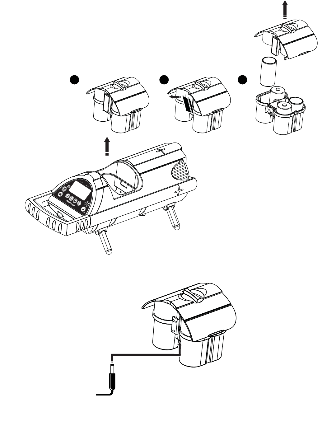
Alkaline Battery Pack
1. To Remove Battery Pack
Remove the Battery Pack from the LMPL20 by turning the Lock Knob on the top of the battery pack and
removing it from the housing. (See Figure 23-1).
2. To replace the Alkaline Batteries
Remove the top portion of the battery pack by lifting the two locking tabs on either side of the battery pack
casing (See Figure 23-2).
Once the battery pack is open, remove depleted batteries and insert fully charged 4 D-Cell Alkaline batteries as
shown in (Figure 23-3).
DO NOT mix batteries, use only like batteries.
DO NOT use new batteries with old batteries.
Place the top of the battery pack back onto the bottom of the battery pack, and lock the two locking tabs on
both sides.
Rechargeable NiMH Battery Pack
1. To Remove NiMH Battery Pack
Remove the Battery Pack from the LMPL20 by turning the Lock Knob on the top of the battery pack and
removing it from the housing .
2. To Charge NiMH Battery Pack External to LMPL20
Plug battery charger into suitable wall outlet.
Insert charge plug of battery charger into NiMH Battery charge port (
See Figure 24
).
The NiMH Battery will take (8-10) hours to fully charge.
It is recommended that the NiMH be fully charged prior to use.
3. To Charge NiMH Battery Pack Internal to LMPL20
With a NiMHbattery pack installed plug a 12 V power supply into the external 12V power port located in the
front of the LMPL20. The 12V supply will then charge the NiMH battery pack during LMPL20 operation and when
the instrument is turned off.
LMPL20 • 13

External 12V Power Port
The external power port is located on the front of the instrument, below the button pad and LCD
Display (See Figure 1 #6).
The external power port may be used to supply the LMPL20 with an external 12V power supply. The external
12V power supply can be used to power the LMPL20 without a battery pack installed, or can be used to charge
a NiMH rechargeable battery pack if inserted in the LMPL20. If a battery pack containing Alkaline non-
rechargeable batteries is inserted in the LMPL20, the 12V supply may still be used without damaging the
batteries or the LMPL20.
Using an external 12 volt DC battery source (Vehicle battery)
1. Turn the vehicle engine off.
2. Make sure to connect the red clip to positive terminal and Black clip to negative terminal.
3. Connect to External Port
Note: Always turn the LMPL20 off before removing external power cable.
MAINTENANCE AND CARE
DO NOT store LMPL20 in cold environment. Moisture can form on interior parts when warming up. This may
cause laser windows to fog and corrosion to internal circuit boards.
DO NOT use aggressive cleaning agents or solvents to clean LMPL20.
REMOVE moisture or dirt from laser windows with a soft, dry cloth.
SPECIFICATIONS
Description 59-LMPL20
Beam Type Red 635nm
Auto Line Centering Yes
Auto Grade Zeroing Yes
Plumb Reference LED
Remote Control Yes
Remote Control Range F/B 800ft/200ft 245m/60m
Grade Range –15% to +40%
Line Range Left / Right 15ft @ 100ft
Self Leveling Range Grade Axis: –15% to +40%, Cross Axis: ± 5°
Horizontal Accuracy ±10" (Arc Seconds)
Power Source NiMH Rechargeable battery pack
Optional Power Source 4 D-Size Alkaline
External Power Source 12vDC
Estimated Battery Life - NiMH: 40 hours
Estimated Battery Life - Alkaline: 60 hours
Housing Construction Cast Aluminum
Operating Temperature –4°F to +122°F
Water waterproof
Nitrogen Purged Yes
Dimensions (LxDia.) 15.5" x 5.0"
Warranty 2 Years
14 • LMPL20

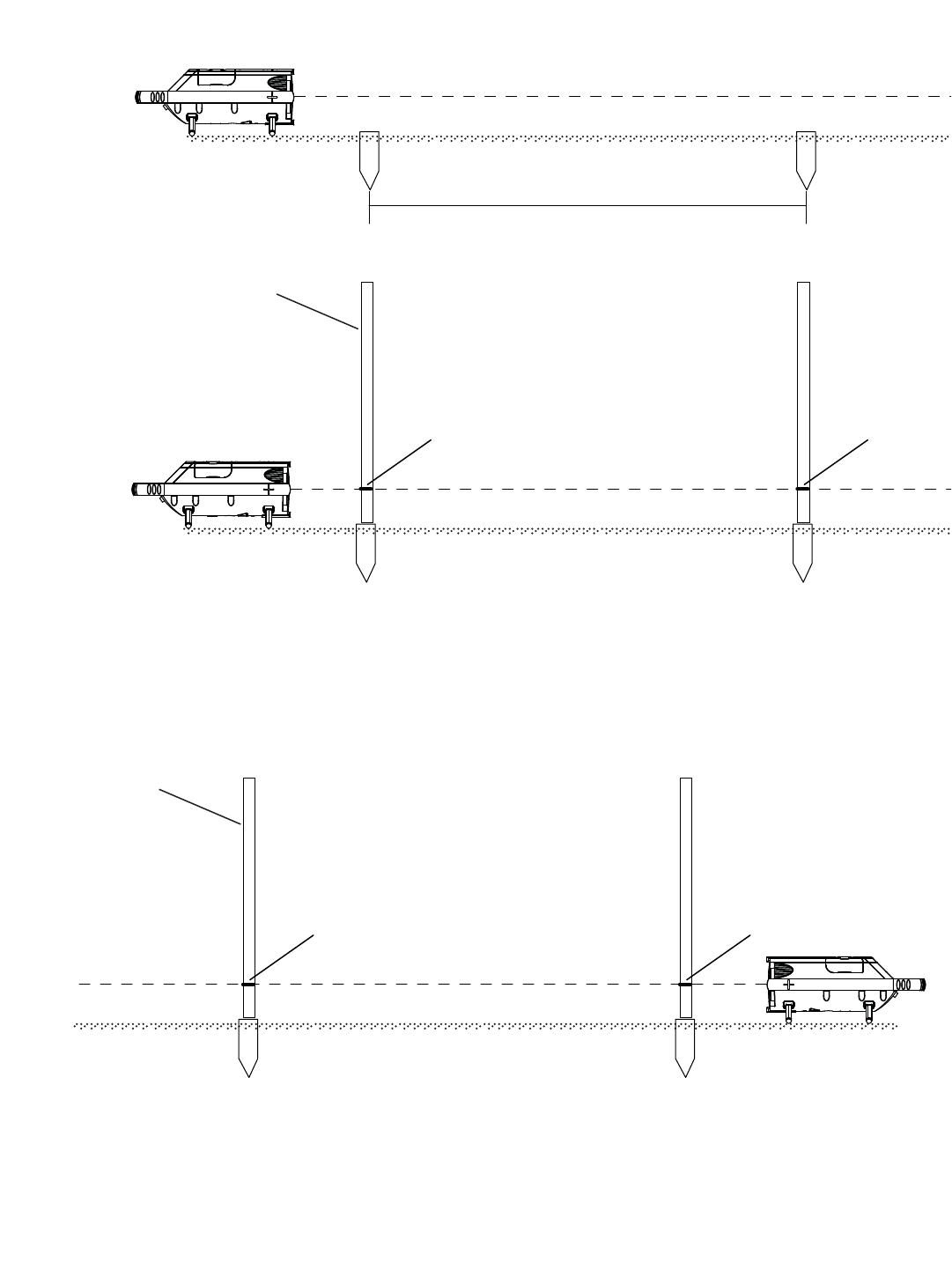
LEVEL ACCURACY CHECK
Seting two benchmarks
Locate a previously level area to set the LMPL20. Level the LMPL20 and set the grade to precisely 0.000% Set
two markers (A and B) in line with the laser. Marker “A” should be set 1’ (.3M) from front of the LMPL20, and
Marker “B” should be set 100’ (30M) away. (Fig. 32)
Level Check
A. Set a measuring rod directly on top of marker ”A”. Mark where the beam strikes the
measuring rod “A1”
B. Set the same measuring rod directly on marker “B” and mark this point “B1” (Fig. 33)
C. Move the LMPL20 to the opposite side of the markers so that it is located 1’ from marker “B” and 100’
away from marker “A”. (Fig. 34)
D. Make sure that the laser beam strikes mark “B1” when the measuring rod is place on marker “B”. If
needed adjust the height of the LMPL 20 so that the laser strikes “B1” (Fig. 34)
E. Now set the measuring rod on marker “A” an if the laser beam strikes mark “A1” . the LMPL20 is
calibrated. If the laser beam did not strike mark “A1” then the unit needs to be calibrated.
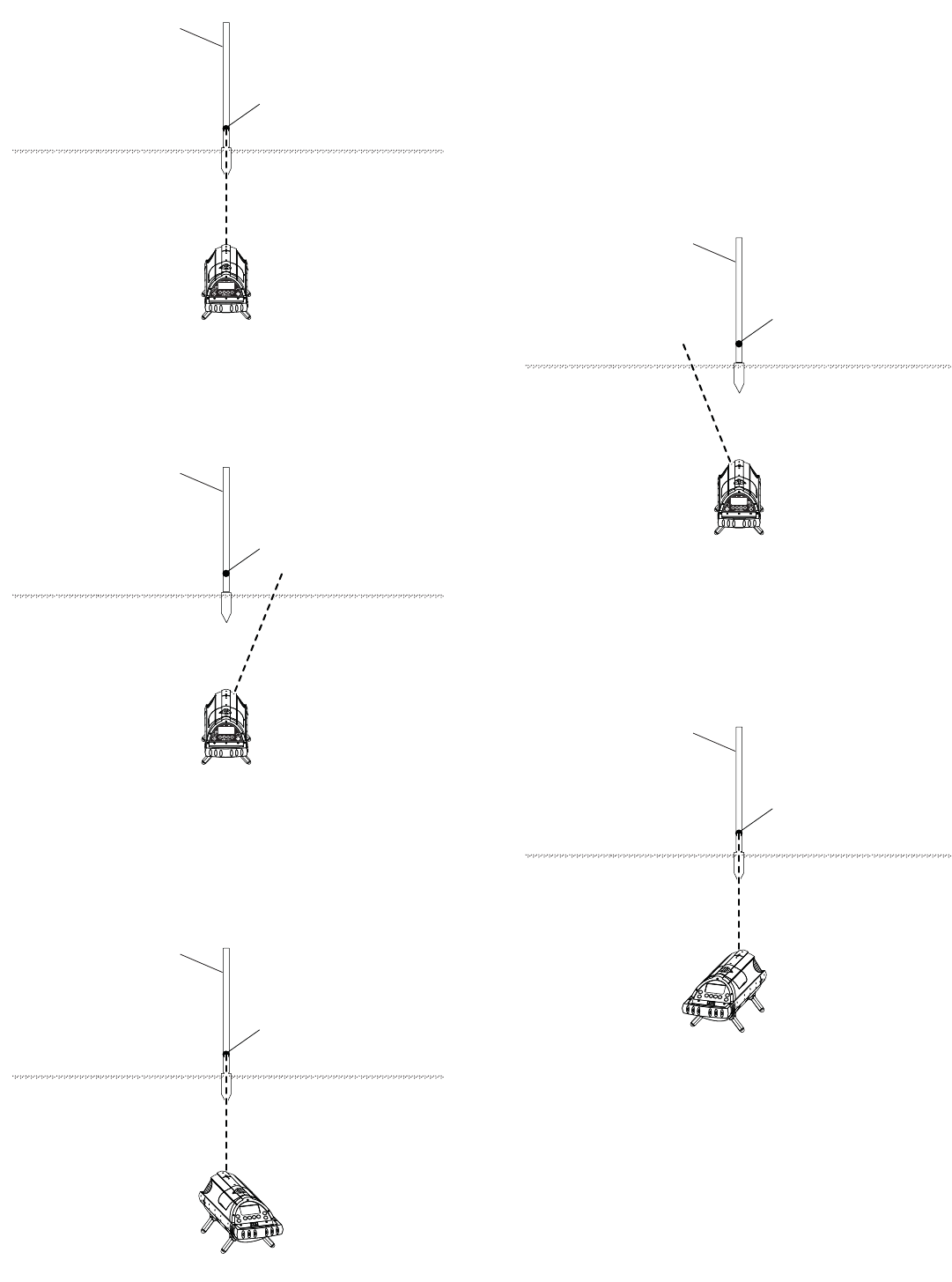
X AXIS CROSS LEVEL CHECK
The LMPL20 offers the option to check and adjust the Calibration of the Horizontal Line Position.
Select XY Calibration from the Menu Display Screen and press the “C” Button.
1. Place the Pipe laser (50) feet from the pole. (See Fig. 35).
2. Turn on the LMPL20 and allow it to self level.
3. Verify that the Line Position is set to the default center position. Point the laser at the Pole and
mark the center of the laser on the Pole.
4. Adjust the Line Position to its maximum right Line Position setting by pressing the “D2” Button.
(See Fig. 36).
5. Turn the LMPL20 so that the laser is pointing at the Pole (See Fig. 37). Allow the LMPL20 to
self level.
6. Compare the laser height of the current maximum right setting to the center mark that was
previously recorded. If they are level with each other, no adjustments need to be made. If they
are not level, follow X axis calibration procedure (see page 16 ).
7. Once the right side has been completed, adjust the line position to its maximum left Line Position
setting by pressing the “D1” button. (See Fig. 38).
8. Turn the LMPL20 so that the laser is pointing at the Pole (See Fig. 39). Allow the LMPL20 to
self level.
9. Compare the laser height of the current maximum left setting to the center mark that was
previously recorded. If they are level with each other, no adjustments need to be made. If they
are not level, follow X axis calibration procedure (see page 16 ).
10. Power off the LMPL20 by pressing the “A” button. Center the LMPL20 and turn it on. Allow it to
self level.
11. Repeat the calibration procedure to verify the previous adjustments are correct. Repeat
as needed.
LMPL20 • 15

PL20 Pipe Laser Calibration Proceedure
XY Calibration Screen
The LMPL20 offers the user the ability to recalibrate.
1. In the Menu Display Screen select XY Calibration Option (Fig. 5 e) and press the “C” button.
2. The XY Calibration Option Screen will appear in the LCD display (Fig. 7).
Y Axis (Grade Axis)
Check calibration as outlined in the calibration or peg test ( see Figures 32 –34 ).
If unit is out of calibration then do the following:
1. Center the line adjustment by pressing left and right adjustment arrows.
2. Zero the grade counter.
3. In the Menu Display Screen select XY Calibration Option (Fig. 5 e) and press the “C” button.
4. Press the Lock key (Fig. F) to enter the Y axis adjustment screen.
5. Using the up(E1) and down (E2) buttons change the laser grade setting (this adjusts the beam without
changing the counter) to the correct elevation.
Note: With the laser beam set all the way to the left (E1) makes the beam go up and (E2) makes the beam go
down. With the laser beam set all the way to the right it is opposite. (E1) makes the beam go down and (E2)
makes the beam go up.
6. Press menu button to accept changes.
7. Recheck Y axis calibration.
X Axis (Cross Axis)
Check the cross axis calibration as outlined in the calibration procedure (see figures 35-39).
1. Center the line adjustment by pressing left and right adjustment arrows.
2. Zero the grade counter.
3. Move the laser spot line adjustment to right or left extreme and check elevation. If incorrect then follow
steps below.
4. In the Menu Display Screen select XY Calibration Option (Fig. 5 e) and press the “C” button.
5. Using the up and down arrows change the laser grade setting (this adjusts the beam without changing
the counter) to the correct elevation.
6. Press menu button to accept changes.
7. Move the laser spot line adjustment to opposite side and repeat the adjustment process.
8. Recheck X axis calibration.
APPLICATIONS
Setting LM-PL20 (All models)
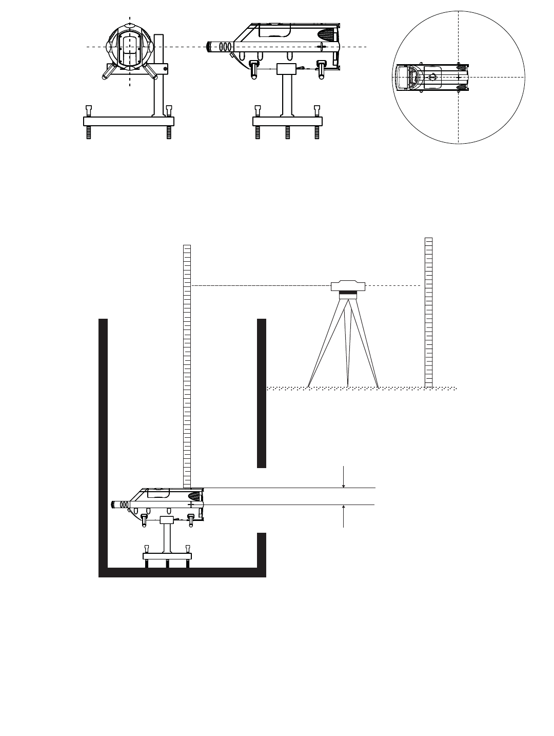
Set Up of the Laser at the Correct Elevation (HI)
All height references are given in relationship to the Invert Elevation (inside lowest point of pipe).
1. Attach the LM-PL20 to the trivet plate or position in the manhole on the correct feet.
Care should be taken that the LMPL20 is positioned on the correct centerline.
2. Use the three leveling screws to adjust the trivet plate to approximate level condition (not required
when mounting on self centering feet with pre-poured inverts - as the invert should be at the
correct elevation).
16 • LMPL20

LMPL20 • 17
3. Where pre-poured inverts are used be sure to attach the correct feet size and set the laser in the center
of the invert (Fig. 26).
4. Use an optical level or rotating laser level to obtain the elevation from the elevation rod or (See Fig. 26)
5. Add the cut amount obtained from the stake to the elevation obtained by the optical level or laser.
6. This dimension is the distance from the optical level or laser to the invert of the pipeline - so subtract
the distance from the invert to the center of the laser spot.
7. Place the grade rod in the manhole at the correct elevation and position the laser at the correct height
in relation to the grade rod.
8. Note that the grade rod can be positioned on the top of the LMPL20 and a correction of - 2.78
inch (70.5mm) is required.
How To Set The Grade
To set grade follow procedures as described in section “Grade” page 8.
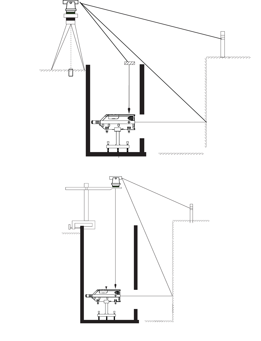
How To Establish and Set Line or Direction
Procedure 1 (Fig. 27)
1. Set the LTU or Transit over the centerline of the pipe using a plumb bob and offset measurement.
2. Position the sighting scope of the transit so that the vertical crosshair is aligned to the next
manhole position of line stake.
3. Plunge the sighting scope into the area where the laser is set up and position the laser pivot or
alignment crosshair point.
4. Bring up the scope so that the vertical crosshair is in the position of the open trench in front of the laser
where the laser spot will project.
5. Using the remote control RC20 drive the line adjustment left or right until the laser spot Is in line with the
vertical crosshair In the scope.
6. The laser housing and the laser spot in front of the laser are now aligned with the axis of the pipeline
stakes and pipe laying can begin.
Procedure 2 (Fig. 28)
1. Mount the Manhole Mount Transit Tower (optional) to the manhole and position the optical
instrument or transit directly over the centerline of the pipeline.
2. Drop a plumb bob down from the optical instrument and position the pipe laser at the pivot point
directly under the plumb bob.
3. Align the optical instrument by the vertical crosshair to the next manhole position stake.
4. After locking the horizontal rotation, plunge the scope into the trench at a convenient spot to view the
laser spot.
5. Using the remote control RC20 drive the left or right direction control until the laser spot is aligned with
the crosshair in the optical instrument.
6. The LMPL20 is aligned with the pipeline axis and pipe laying can begin.
Procedure 3 ( LMPL20 )
1. Position the LMPL20 exactly in the center of a poured invent or centerline marked on the bottom
of the manhole so that the pivot point is on the centerline.
2. Attach the loose end of a plumb bob cord to the notch on the LMPL20 at the pivot point.
3. Extend this cord to the top of the manhole and so that the cord is supported over the thumb of the
operator. The free end with the plumb bob then hangs from the thumb of the operator.
4. Using the cord from the thumb to the plumb bob as a guide move the thumb left or right until both sides
of the cord are vertical and aligned with the next manhole stake.
5. Using the remote control RC20 drive the left or right direction control until the laser spot is aligned with
the both of the vertical cords.
6. The LMPL20 is aligned with the pipeline axis and pipe laying can begin.

18 • LMPL20
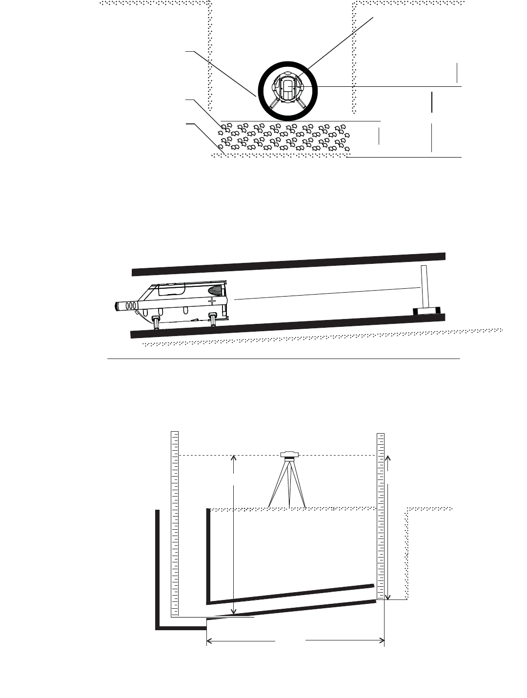
Setting Excavation, Base Material and Pipe Elevation (Fig. 29)
1. To accurately set the base elevation for pipe laser use, you must be able to calculate the base elevation
from the center of the pipe laser beam.
Using the sample information below, you will be able to calculate your base elevation as described above.
• Consider a pipe diameter of 12" (300mm)
• Use a pipe thickness of 1" (25mm)
• Consider a base material thickness of 6" (150mm)
Example:
To calculate the base elevation, take the pipe radius 12" divided by 2 = 6" (300mm/2 = 150mm)
Next using the pipe thickness and the base material (1" or 25mm) and (6" or 150mm) respectively
Calculate the distance from beam to base elevation as follows
Pipe Radius + Pipe Thickness + Base Material Thickness = Base Elevation
6" + 1" + 6" = 13" or 150mm + 25mm + 150mm = 325mm
2. You may now utilize any leveling rod, direct elevation rod or grade stick and the pipe laser beam to
control the excavation depth by marking a reference point on your rod at the height detailed above, (13"
or 325mm). Utilize the beam control of the LM-PL20 to match up to the marks on the grade stick or
level rod.
3. In some cases, it may be necessary to set a sub base elevation to begin work. To set a sub-base
elevation, calculate the distance from the center of the beam as follows:
Example:
To calculate the sub-base, utilize the information below.
Pipe Diameter: 12" (300mm) as detailed in the example above
Pipe thickness: 1" (25mm) as detailed in the example above
Distance from beam to sub base elevation
To calculate the first step, take the pipe radius 12" divided by 2 = 6" (300mm/2 = 150mm)
Next using the pipe thickness and the base material (1" or 25mm) and (6" or 150mm) respectively
Calculate the sub-base elevation as follows
Pipe Radius + Pipe Thickness = Sub-Base Elevation
6" + 1" = 7" or 150mm + 25mm = 175mm
4. You may now utilize any leveling rod, direct elevation rod or grade stick and the pipe laser beam to
control the elevation of the sub-base material by marking a reference point on your rod at the
height detailed above, (7" or 175mm).
5. Finally to set the LMPL20 to the correct elevation for use, place the pipe target in the pipe using the
target associated with the size of pipe you are setting. Then adjust the pipe until the laser beam is
precisely in the center of the alignment center of the target. Ensure that the center of the beam is
exactly in the center of the bulls-eye on the target. Once there, set the pipe and fill accordingly to
maintain grade.
In-the-Pipe Set up. (Fig. 30)
Assuming that some pipe has already been installed or laid, the LM-PL20 Pipe Laser can easily be positioned
inside the pipe for additional use.

LMPL20 • 19
1. Install the correct leg set for the pipe wishing to be installed
2. Place the pipe laser into the last section of pipe and ensure that the LMPL20 is positioned at the right
rotation and direction. Review the steps to ensure level and direction.
3. Place the pipe target in the last section of pipe to install ensuring the target is also positioned so that it
is level using the level vial on the target mount.
4. Using the included Remote Control or the LMPL20 keypad, guide the pipe laser beam so that it is in the
center of the target. You may use the remote control from the position of the end target to guide
the beam.
This will ensure accuracy in set up and allow one person to set the LMPL20 up for use. By using the LMPL20
keypad, it may be necessary to have a person at both the LMPL20 and target in order to guide the laser beam to
the center of the target.
Refer to section of Preparing LMPL20 for use for additional set up information.
Grade Checking (Fig. 31)
In order to ensure that you are laying pipe at the correct grade, it may be necessary to check pipe grade to
ensure that the laser has been set for the appropriate grade and line. This should be completed after
approximately 25 to 50ft (8 to 15m) pipe has been installed.
1. Utilizing an Automatic Level or Level Transit, measure a reference elevation at starting point
A. (See Figure 31)
2. Measure the elevation at ending point B with the level or level transit
3. Determine the elevation of pipe end point B in the same manner.
4. Using the standard Rise over Run X 100 calculation you can easily determine the grade.
Take (A-B) = Rise
Take Horizontal Distance = Run
((A-B)/Hz Distance) X 100 and you will have the grade of the installed sections.
If your measured grade does not match the intended grade, please review your initial laser or target set up to
ensure accurate LMPL20 set up.

WARRANTY
Two Year Warranty. Robert Bosch Tool Corporation ("Seller") warrants to the original
purchaser only, that this CST/berger laser tool product will be free from defects in material or workmanship for
a period of two (2) years from date of purchase.
SELLER'S SOLE OBLIGATION AND YOUR EXCLUSIVE REMEDY under this Limited Warranty and, to the extent
permitted by law, any warranty or condition implied by law, shall be the repair or replacement of laser and
measuring tool products, which are defective in material or workmanship and which have not been misused,
carelessly handled, or misrepaired by persons other than Seller or Seller Authorized Service providers.
To make a claim under this Limited Warranty, you must return the complete product, transportation prepaid. For
details, please contact the factory direct service line at 1-815-432-9200.
ANY IMPLIED WARRANTIES SHALL BE LIMITED IN DURATION TO ONE YEAR FROM DATE OF
PURCHASE. SOME STATES IN THE U.S., AND SOME CANADIAN PROVINCES DO NOT ALLOW LIMITATIONS ON
HOW LONG AN IMPLIED WARRANTY LASTS, SO THE ABOVE LIMITATION MAY NOT APPLY TO YOU.
IN NO EVENT SHALL SELLER BE LIABLE FOR ANY INCIDENTAL OR CONSEQUENTIAL DAMAGES (INCLUDING
BUT NOT LIMITED TO LIABILITY FOR LOSS OF PROFITS) ARISING FROM THE SALE OR USE OF THIS PRODUCT.
SOME STATES IN THE U.S., AND SOME CANADIAN PROVINCES DO NOT ALLOW THE EXCLUSION OR
LIMITATION OF INCIDENTAL OR CONSEQUENTIAL DAMAGES, SO THE ABOVE LIMITATION MAY NOT APPLY
TO YOU.
THIS LIMITED WARRANTY GIVES YOU SPECIFIC LEGAL RIGHTS, AND YOU MAY ALSO HAVE OTHER RIGHTS
WHICH VARY FROM STATE TO STATE IN THE U.S., OR PROVINCE TO PROVINCE IN CANADA AND FROM
COUNTRY TO COUNTRY.
THIS LIMITED WARRANTY APPLIES ONLY TO PRODUCTS SOLD WITHIN THE UNITED STATES OF AMERICA,
CANADA AND THE COMMONWEALTH OF PUERTO RICO. FOR WARRANTY COVERAGE WITHIN OTHER
COUNTRIES, CONTACT YOUR LOCAL BOSCH OR CST/BERGER DEALER OR IMPORTER.
CST/berger is a trademark of Robert Bosch Tool Corporation
20 • LMPL20
LMPL20 • 21
LMPL20
LMPL20
LMPL20
m
SEL
B
1 2 3
Fig. 23
Fig. 24
22 • LMPL20
Fig. 25
Fig. 26
ab
LMPL20LMPL20LMPL20
m
SEL
+00.123%
LOCK
D
70.5mm
(2.78 in.)
Laser beam
Grade rod
Level
Grade rod
LMPL20 • 23
Fig. 27
Fig. 28
Laser beam
Plumb bob
Transit
Forward manhole
marker
Manhole
Transit
Forward manhole
marker
Manhole
transit tower
(option)
Plumb bob
Manhole
Laser beam
24 • LMPL20
Fig.29
Fig. 30
Target
Pipe
Sub-base material
Base
Sub-base
elevation
Base elevation
Pipe
Laser beam
LMPL20
Pipe laser target
Fig. 31
Grade rodGrade rod
Level
Pipe
Manhole 8 - 15m
AB
LMPL20 • 25
Fig. 32
Marker
“A”
Marker
“B”
100 ‘
LMPL20
Marker
“A”
Marker
“B”
Measuring Rod
Mark “A1” Mark “B1”
Fig. 33
Marker
“A”
Marker
“B”
Measuring Rod
Mark “A1” Mark “B1”
Fig. 34
26 • LMPL20
Measuring Rod
Reference Mark
LMPL20LMPL20LMPL20
m
SEL
D
Measuring Rod
Reference Mark
LMPL20LMPL20LMPL20
m
SEL
D
Measuring Rod
Reference Mark
Measuring Rod
Reference Mark
LMPL20LMPL20LMPL20
m
SEL
D
Measuring Rod
Reference Mark
Fig. 35
Fig. 36
Fig. 37
Fig. 38
Fig. 39

LMPL20 • 27

© Robert Bosch Tool Corporation, 1800 W. Central Road Mt. Prospect, IL 60056-2230
Exportado por: Robert Bosch Tool Corporation Mt. Prospect, IL 60056-2230, E.U.A.
Importado en México por: Robert Bosch, S.A. de C.V., Calle Robert Bosch No. 405, Zona Industrial,
Toluca, Edo. de México, C.P. 50070, Tel. (722) 2792300
Robert Bosch GmbH
Power Tools Division, 70745 Leinfelden-Echterdingen, Germany
www.bosch-pt.com <http://www.bosch-pt.com>
www.cstberger.com
11/09 P/N Z94-LMPL20 REV4