Robert Bosch Tool GLM400C Laser Rangefinder User Manual TXTGLM400C UserMan
Robert Bosch Tool Corporation Laser Rangefinder TXTGLM400C UserMan
UserManual.wiki
>
Robert Bosch Tool
>
GLM400C User Manual
>
TXTGLM400C UserMan
Contents
1.
TXTGLM400C UserMan
2.
GLM400C Final UserMan
3.
GLM400CL Final UserMan
TXTGLM400C UserMan
Navigation menu
Upload a User Manual
Namespaces
Wiki Guide
HTML
PDF
Info
Views
User Manual
Discussion / Help
Navigation

![21Do not leave the switched on measuring tool unattended and switch the tool off after use. Other persons could be blinded by the laser beam.Switching On and OffDuring work, ensure that the reception lens 20, laser beam output 18, and digital viewfinder 19 are not closed off or covered, otherwise correct measurement will not be possible.– To switch on the measuring tool and the laser, briefly press the On/Off button 9 [ ], front or side measuring button 2 [ ].Do not point the laser beam at persons or animals and do not look into the laser beam yourself, not even from a large distance.– To switch off the laser, press the On/Off button 9 [ ].– To switch off the digital viewfinder, press the digital viewfinder button 10.– To switch off the measuring tool, press and hold the On/Off button 9 [ ].The measured values and device settings in the memory are retained when you switch the tool off.Measuring ProcedureOnce switched on, the measuring tool is in the continuous laser measurement function. For a different measuring function, press the button 13 [Func]. Select the desired measuring function with the buttons 4 [+] or the button 11 [–] (see “Measuring Functions”, page 27). Activate the measuring function with button 13 [Func] or with the measuring button 2 [ ].After switching on, the rear edge of the measuring tool is preset as the reference level for the measurement. To change the reference level, see “Selecting the Reference Level”, page 22.Place the measuring tool against the desired starting point of the measurement (e.g. a wall).Note: If the measuring tool has been switched on using the On/Off button 9 [ ], briefly press the measuring button 2 [ ] to switch the laser on.2610049010 10-17 GLM400C.indd 21 11/3/17 1:09 PM](https://usermanual.wiki/Robert-Bosch-Tool/GLM400C.TXTGLM400C-UserMan/User-Guide-3754331-Page-21.png)
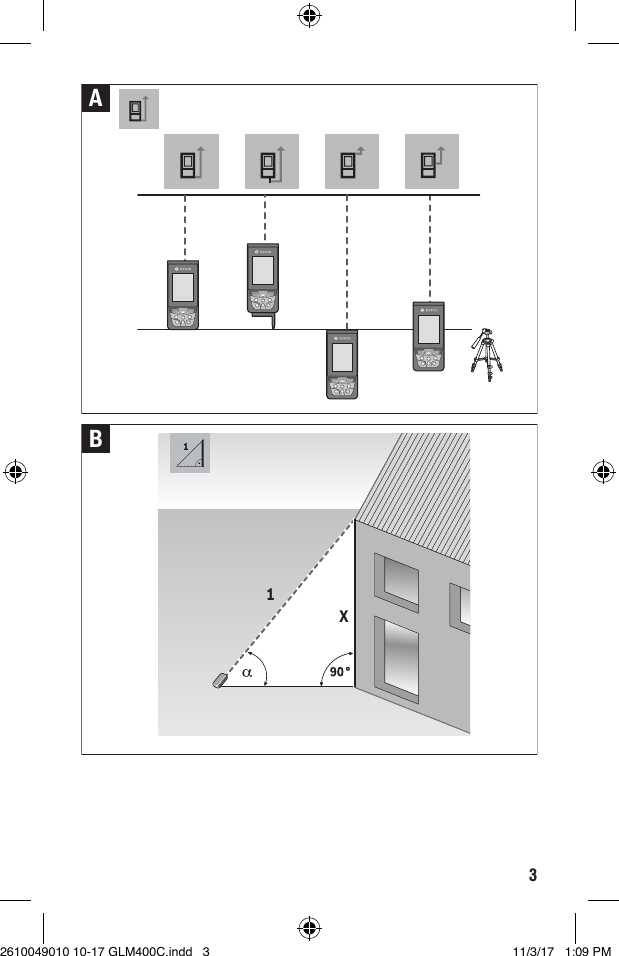
![22To initiate the measurement, briefly press the measuring button 2 [ ]. Then the laser beam is switched off. For a further measurement, repeat this process.With the laser beam continuously switched on and in the the continuous measurement function, measurement will begin after the measuring button 2 [ ] is pressed for the first time. Do not point the laser beam at persons or animals and do not look into the laser beam yourself, not even from a large distance.Note: The measured value typically appears within 0.5 s and no later than approx. 4 s. The duration of the measurement depends on the distance, the lighting conditions and the reflective properties of the target surface. Upon completion of the measurement, the laser beam is automatically switched off. The continuously switched-on laser beam is not switched off after the measurement (see “Continuous Laser Beam”, page 23).Selecting the Reference Level (see figure A)You can choose between four different reference levels for the measurement:– the rear measuring-tool edge (e.g. when measuring onward from a wall),– the tip of the 180° folded-out measuring pin 8 (e.g. when measuring from a corner),– the front measuring-tool edge (e.g. when measuring onward from a table edge),– the center of thread 17 (e.g. for tripod measurements). Folding out and in of the measuring pin 8 by 180° is detected automatically and the appropriate reference level is suggested. Confirm the setting by pressing the measuring button 2 [ ].Use the soft key 3 [ ] to select the basic settings for the measuring tool. Use buttons 4 [+] or 11 [–] to select the reference level and confirm this by pressing button 13 [Func].The rear edge of the measuring tool is automatically preset as the reference level every time the measuring tool is switched on.2610049010 10-17 GLM400C.indd 22 11/3/17 1:09 PM](https://usermanual.wiki/Robert-Bosch-Tool/GLM400C.TXTGLM400C-UserMan/User-Guide-3754331-Page-22.png)
![23Permanent Laser BeamIf necessary, you can switch the measuring tool to permanent laser beam operation. To do so, use soft key 3 [ ] to select the basic settings for the measuring tool. Use buttons 4 [+] or 11 [–] to select the permanent laser beam and confirm this by pressing button 13 [Func].Do not point the laser beam at persons or animals and do not look into the laser beam yourself, not even from a large distance.In this setting, the laser beam remains switched on even between measurements; measurement simply requires one brief press of the measuring button 2 [ ].The permanent laser beam can be switched off again in the basic settings or automatically when the measuring tool is switched off.“Settings” MenuTo enter the “settings” menu (i) briefly press soft key 3 [ ] or press and hold button 13 [Func].Use button 4 [+] or 11 [–] to select the relevant basic setting and press button 13 [Func] to select the required setting.To exit the “settings” menu, press the On/Off button 9 [ ] or soft key 12 [ ]. Settings CALBluetooth®CALReference LevelCALMeas TimerCALPermanent LaserCALTilt CalibrationViewfinder CalibrationCALMemoryCALTool Settings2610049010 10-17 GLM400C.indd 23 11/3/17 1:09 PM](https://usermanual.wiki/Robert-Bosch-Tool/GLM400C.TXTGLM400C-UserMan/User-Guide-3754331-Page-23.png)
![24Timer FunctionThe timer function is useful when measuring in hard-to-reach areas, for example, or when the measuring tool should be kept stationary during measurement.Select the timer function in the settings. Select the required time period between triggering the timer and starting measurement and confirm by pressing the measuring button 2 [ ] or button 13 [Func].Next, press the measuring button 2 [ ] to switch on the laser beam and focus on the target. Press the measuring button 2 [ ] once more to start the measurement. The measurement will begin after the set time period has expired. The measured value is displayed in the result line a.The time period between triggering the timer and starting measurement is displayed in the status bar at the top.Continuous measurement and minimum/maximum measurement are not possible with the timer function enabled.The timer remains enabled until the measuring tool is switched off or until the timer is switched off in the menu “settings”.Digital ViewfinderTo switch on the digital viewfinder 19, press the digital viewfinder button 10.The digital viewfinder 19 is optimized for the detection of the laser point from a distance and therefore has a small visual field.Optimizing visibility of the laser beamEspecially when using the measuring tool outdoors, in sunlight and also over long distances indoors, it may be that the laser point is not visible. The visibility of the laser point/measuring target can be improved additionally to switching on the camera by:– Setting the display brightness (tool settings)– Using the zoom by pressing button 52610049010 10-17 GLM400C.indd 24 11/3/17 1:09 PM](https://usermanual.wiki/Robert-Bosch-Tool/GLM400C.TXTGLM400C-UserMan/User-Guide-3754331-Page-24.png)
![25“Tool Settings” MenuSelect the menu “Tool Settings” in the menu “Settings”.Use button 4 [+] or 11 [–] to select the desired tool setting and confirm with button 13 [Func]. Select the desired tool setting.To exit the “Tool” menu (o), press the On/Off/Clear button 9 [ ] or soft key 12 [ ]. Tool Settings LanguageTime & Dateft/m Measurement UnitAngle UnitTrackMyToolsTool InformationAudio SignalsShutdown TimeDimmingBrightnessAuto RotateSetting the languageSelect the language in the basic settings (general settings).Set the required language and confirm by pressing button 13 [Func] or button 2 (measuring).Setting the date and timeSelect the date and time in the basic settings (general settings).Set the date and time and confirm by pressing soft key 12 [ ].2610049010 10-17 GLM400C.indd 25 11/3/17 1:09 PM](https://usermanual.wiki/Robert-Bosch-Tool/GLM400C.TXTGLM400C-UserMan/User-Guide-3754331-Page-25.png)
![26Changing the Unit of MeasureSelect the “Measurement unit” in the tool settings.Unit of measure “in” (inches) is set by default.Set the required unit of measure and confirm by pressing button 13 [Func].To exit the menu item, press the On/Off/Clear button 9 [ ] or soft key 3 [ ]. The selected setting remains saved after you switch off the measuring tool.Changing the Angle UnitSelect the “Angle unit” in the tool settings.Angle unit “°” (grade) is set by default.Set the required angle unit and confirm by pressing button 13 [Func].To exit the menu item, press the On/Off/Clear button 9 [ ] or soft key 3 [ ]. The selected setting remains saved after you switch off the measuring tool.TrackMyToolsSelect “TrackMyTools” in the tool settings.Confirm the setting by pressing button 13 [Func].An initial activation is required. Data transmission is only possible with the corresponding app or the corresponding PC program. After exchanging the batteries, the tool has to be switched on shortly to re-activate TrackMyTools.TrackMyTools can be disabled at any time.Display IlluminationSelect the display illumination in the basic settings (general settings).The display illumination is continuously switched on. When no button is pressed, the display illumination is dimmed after approx. 30 seconds to preserve the batteries.The time until start of dimming is adjustable (tool settings).The brightness of the display can be adjusted to the surrounding conditions in multiple increments (general settings).2610049010 10-17 GLM400C.indd 26 11/3/17 1:09 PM](https://usermanual.wiki/Robert-Bosch-Tool/GLM400C.TXTGLM400C-UserMan/User-Guide-3754331-Page-26.png)
![27Measuring FunctionsNote: Integrated Help FunctionHelp in the form of an animation is stored in the measuring tool for each measuring function. To do so, select button 13 [Func], buttons 4 [+] or 11 [–] and then soft key 3 [ ].The animation shows you the detailed procedure for the selected measuring function. The animation can be stopped and started again at any time. You can scroll forward and back with buttons 4 [+] or 11 [–].Length MeasurementSelect the length measurement .To switch on the laser beam, briefly press the measuring button 2 [ ].09.06.201713:20:230.0º76´01˝⁄45´08˝60´10˝⅝30´05˝To measure, briefly press the measuring button 2 [ ]. The measured value will be shown at the bottom of the display.Repeat the above-mentioned steps for each subsequent measurement. The last measured value is at the bottom of the display, the penultimate measured value is above it, and so on.Continuous Measurement (Tracking)For continuous measurements, the measuring tool can be moved relative to the target, whereby the measuring value is updated approx. every 0.5 seconds. In this manner, as an example, you can move a certain distance away from a wall, while the actual distance can always be read.Select the continuous measurement .To switch on the laser beam, briefly press the measuring button 2 [ ].Move the measuring tool until the required distance value is indicated in the bottom of the display.09.06.201713:20:230.0ºmaxmin30´05˝76´01˝⁄76´01˝⁄Briefly pressing the measuring button 2 [ ] interrupts the continuous measurement. The current measured value will be shown at the bottom of the display. The maximum and minimum measured value appear above it. Pressing the measuring button 2 [ ] once more restarts the continuous measurement.Continuous measurement automatically switches off after 5 mins.2610049010 10-17 GLM400C.indd 27 11/3/17 1:09 PM](https://usermanual.wiki/Robert-Bosch-Tool/GLM400C.TXTGLM400C-UserMan/User-Guide-3754331-Page-27.png)
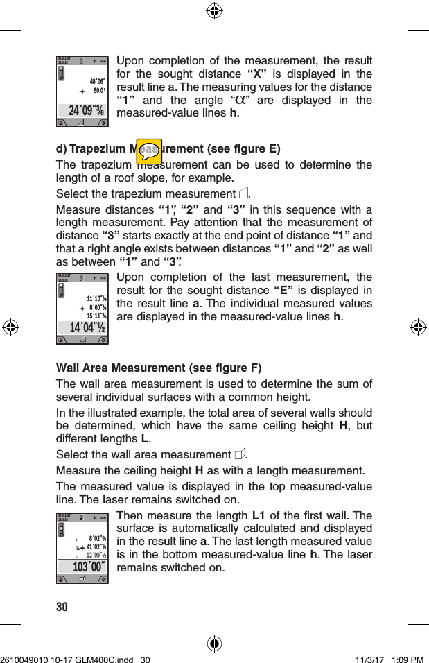
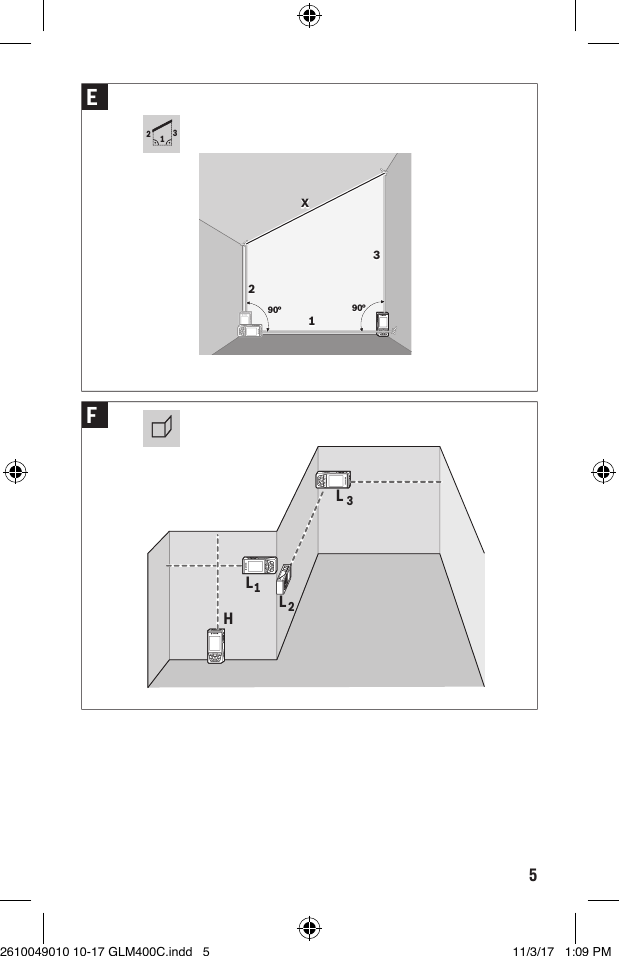
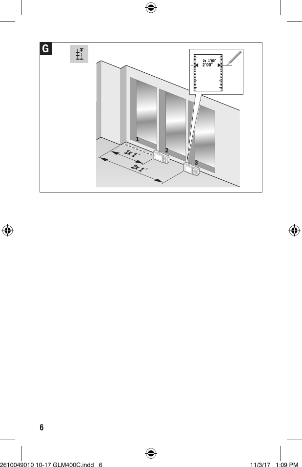
![31Now measure the length L2 of the second wall. The individual measured value displayed in the measured-value line h is added to the length L1. The sum of the two lengths (displayed in the bottom measured-value line h) is multiplied by the saved height H. The total surface value is displayed in the result line a.You can measure any number of lengths LX, which will be automatically added and multiplied by the height H.The requirement for a correct area calculation is that the first measured length (for example the ceiling height H) is identical for all sub-areas.Stake out function (see figure G)The stake out function repeatedly measures a defined length (distance). These lengths can be transferred to a surface, for example to enable material to be cut into pieces of equal lengths or to install stud walls in a drywall construction. The minimum adjustable length is 3.2 ft (0,1m), the maximum adjustable length is 164 ft (50m).Select the stake out function .Set the desired length. Using button 13 [Func] select the corresponding digit/position and change the value with button 4 [+] or button 11 [–].Begin the stake out function by pressing the measuring button 2 [ ] and slowly move away from the starting point.0´08˝1´04˝10.5xThe measuring tool continuously measures the distance to the starting point. The defined length and the current measured value are thereby displayed. The lower or upper arrow displays the shortest distance to the next or last marking.Note: The continuous measuring enables you to set a measured value as a defined length by pressing the button 3.1´04˝1´04˝1xThe left factor specifies how many times the defined length has already been reached. The green arrows on either side of the display indicate the reaching of a length for marking purposes.Red arrows or a red label indicate the actual value if the reference value is outside the display.2610049010 10-17 GLM400C.indd 31 11/3/17 1:09 PM](https://usermanual.wiki/Robert-Bosch-Tool/GLM400C.TXTGLM400C-UserMan/User-Guide-3754331-Page-31.png)
![32Gradient Measurement/Digital Spirit LevelSelect the inclination measurement/digital spirit level .The measuring tool automatically switches between two states.1° 2° 3°The digital spirit level is used to check the horizontal or vertical alignment of an object (e.g. washing machine, refrigerator, etc.). When the inclination 3° exceeds, the ball in the display lights red.88.0°Gradient measurement is used to measure a slope or incline (e.g. of stairs, railings, when fitting furniture, laying pipes, etc.). The left-hand side of the measuring tool serves as the reference level for grade measurement. If the display flashes during measurement, the measuring tool has been tipped too heavily to the side.Memory FunctionsThe value or end result of each completed measurement is automatically saved.Tip: You can save your measurement as a photo for reference.The following information is printed on the photo:– Measuring result– Measuring function used– Reference– Date and time– Tilt angle (only with spirit level switched on).Memory value displayA maximum of 50 values can be retrieved (measured values or photos with measured values.Select the memory function using soft key 12 [ ].09.06.201713:20:2330º76´01˝⁄4430´05˝45´08˝60´10˝⅝The number of the memory value is shown at the top of the display, the corresponding memory value is shown at the bottom and the corresponding measuring function is shown on the left.Press button 4 [+] to browse forwards through the saved values.2610049010 10-17 GLM400C.indd 32 11/3/17 1:09 PM](https://usermanual.wiki/Robert-Bosch-Tool/GLM400C.TXTGLM400C-UserMan/User-Guide-3754331-Page-32.png)
![33Press button 11 [–] to browse backwards through the saved values.If there is no value available in the memory, “0.000” is shown at the bottom of the display and “0” at the top.The oldest value is located in position 1 in the memory, while the newest value is in position 50 (when 50 memory values are available). When a further value is saved, the oldest value in the memory is always deleted.Deleting the MemoryTo delete the content of the memory, press soft key 12 [ ] and then, as many times as required, press soft key 3 [ ].To delete all values stored in the memory, the function can be used. Confirm by pressing soft key 12 [ ].Adding/Subtracting ValuesMeasured values or end results can be added or subtracted.Adding ValuesThe following example describes the addition of areas:Measure an area as described in section “Area Measurement”, see page 28.209.06.201713:20:230.0º185 ft22168 ft17 ft+Press the button 4 [+]. The calculated area and the symbol “+” will be displayed.Press the measuring button 2 [ ] to start another area measurement. Measure the area as described in section “Area Measurement”, see page 28. Once the second measurement is completed, the result of the second area measurement is displayed below. To show the end result, press the measurement button 2 [ ] once more.Note: With a length measurement, the end result is displayed immediately.Subtracting ValuesTo subtract values, press button 11 [–]. The subsequent steps are the same as for “Adding Values”.Deleting Measured ValuesBriefly pressing the On/Off/Clear button 9 [ ] will delete the last measured value in all measuring functions. 2610049010 10-17 GLM400C.indd 33 11/3/17 1:09 PM](https://usermanual.wiki/Robert-Bosch-Tool/GLM400C.TXTGLM400C-UserMan/User-Guide-3754331-Page-33.png)
![34Bluetooth® InterfaceData Transmission to other DevicesThe measuring tool is equipped with a Bluetooth® module, which enables data transmission via radio technology to certain mobile terminals/devices with a Bluetooth® interface (e.g., smartphones, tablets).For information on the necessary system requirements for a Bluetooth® connection, please refer to the Bosch website at www.bosch-pt.comFurther information can be found on the Bosch product page.For data transmission via Bluetooth®, time delays between mobile terminal/device and measuring tool may occur. This can be possible due to the distance between both devices or the object being measured.Activating the Bluetooth® Interface for Data Transmission to a Mobile Terminal/DeviceThe Bluetooth® interface is activated in the basic settings. To activate the Bluetooth® signal, press button 4 [+]. Ensure that the Bluetooth® interface is activated on your mobile end device.The special Bosch “Measuring Master” app is available to extend the range of functions of the mobile end device and to make data easier to process. You can download this from the store for your end device type.The connection between mobile terminal/device and measuring tool is established after the Bosch application has started. If multiple active measuring tools are found, select the appropriate measuring tool using the serial number.The connection status, as well as the active connection (f), are shown in the display 1 of the measuring tool.Deactivating the Bluetooth® InterfaceThe Bluetooth® connection is deactivated in the basic settings. To deactivate the Bluetooth® signal, press button 11 [–] or switch off the measuring tool.2610049010 10-17 GLM400C.indd 34 11/3/17 1:09 PM](https://usermanual.wiki/Robert-Bosch-Tool/GLM400C.TXTGLM400C-UserMan/User-Guide-3754331-Page-34.png)