Robert Bosch Tool GLM400C Laser Rangefinder User Manual TXTGLM400C UserMan
Robert Bosch Tool Corporation Laser Rangefinder TXTGLM400C UserMan
Contents
- 1. TXTGLM400C UserMan
- 2. GLM400C Final UserMan
- 3. GLM400CL Final UserMan
TXTGLM400C UserMan
IMPORTANT:
Read Before Using IMPORTANT :
Lire avant usage IMPORTANTE:
Leer antes de usar
For English Version
See page 4 Version française
Voir page 44 Versión en español
Ver la página 83
Operating/Safety Instructions
Consignes d’utilisation/de sécurité
Instrucciones de funcionamiento
y seguridad
1-877-BOSCH99 (1-877-267-2499) www.boschtools.com
GLM400C
Call Toll Free for Consumer Information and Service Locations
Pour obtenir des informations et les adresses de nos centers de service
après-vente, appelez ce numéro gratuit
Llame gratis para obtener información para el consumidor y
ubicaciones de servicio
2610049010 10-17 GLM400C.indd 1 11/3/17 1:09 PM
2
24
14
20 17
18
19
23
8
10
9
11 12
2
13
21
43
6
7516
22
21
GLM400C
LASER RADIATION. DO NOT STARE INTO BEAM. CLASS 2
LASER PRODUCT. COMPLIES WITH 21 CFR 1040.10 AND
1040.11 EXCEPT FOR DEVIATIONS PURSUANT TO LASER
NOTICE 50, 6/24/2007
RADIACIÓN LÁSER. NO MIRE AL RAYO. PRODUCTO LÁSER
DE CLASE 2. CUMPLE CON LAS NORMAS 21 CFR 1040.10
Y 1040.11, EXCEPTO POR LAS DESVIACIONES CONFORME
AL AVISO PARA LÁSERES 50 DEL 24 DE JUNIO DE 2007
GLM 400 C
3601K72F10
3x1.5V (AA)
Robert Bosch
Tool Corp.,
Mount Prospect, IL
Made in Malaysia
FCC ID: TXTGLM400C
IC:909H-GLM400C
RAYONNEMENT LASER. NE REGARDEZ PAS DIRECTE-
MENT DANS LE FAISCEAU. PRODUIT LASER DE
CLASS E 2. CONFORME À 21 CFR 1040.10 ET
1040.11, SAUF POUR LES ÉCARTS SUIVANT L'AVIS
LASER 50, 24/6/2007
IEC 60825-1:2014
<1mW, 650 nm
2
15
Language
Tool
Bluetooth
Settings
CAL
CAL
76´01˝⁄
05.05.2017
7:26:12
30º
30´05˝
60´10˝⅝
45´08˝
Length
Tool
i
i
jk
hfed g
a
b
c
m l
j
n
o
2610049010 10-17 GLM400C.indd 2 11/3/17 1:09 PM
3
X
1
1
A
B
2610049010 10-17 GLM400C.indd 3 11/3/17 1:09 PM
4
D
X
1
1
C
1
2
X
1
2
2610049010 10-17 GLM400C.indd 4 11/3/17 1:09 PM
5
F
Professional
GLM 120 C
L1
L3
L2
H
Professional
GLM 120 C
Professional
GLM 120 C
E
1
X
3
13
2
Professional
GLM 120 C
2
90°
Professional
GLM 120 C
Professional
GLM 120 C
90°
2610049010 10-17 GLM400C.indd 5 11/3/17 1:09 PM
6
1´00˝2x
2´00˝
G
1
2
3
1x 1´
2x 1´
2610049010 10-17 GLM400C.indd 6 11/3/17 1:09 PM
7
90° 180°
180°
90°
180°
180º
90º
90º
180º
180º
H
2610049010 10-17 GLM400C.indd 7 11/3/17 1:09 PM
8
1 608 M00 05B
25
2 607 001 391
26
BT 150
0 601 096 B00
27
2610049010 10-17 GLM400C.indd 8 11/3/17 1:09 PM
9
General Safety Rules
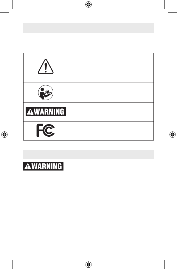
Safety Symbols
The definitions below describe the level of severity for each
signal word. Please read the manual and pay attention to these
symbols.
Work area safety
Keep work area clean and well lit. Cluttered or dark areas
invite accidents.
DO NOT operate the laser tool around children or allow chil-
dren to operate the laser tool. Serious eye injury could result.
Read all instructions. Failure to follow all
instructions listed below may result in
hazardous radiation exposure, electric shock, fire and/or
serious injury. The term “tool” in the warnings listed below
refers to your mains-operated (corded) tool or battery-operated
(cordless) tool.
SAVE ALL WARNINGS AND INSTRUCTIONS
FOR FUTURE REFERENCE
This is the safety alert symbol. It is
used to alert you to potential personal
injury hazards. Obey all safety
messages that follow this symbol to
avoid possible injury or death.
Read manual symbol - Alerts user to
read manual.
WARNING indicates a hazardous
situation which, if not avoided, could
result in death or serious injury.
This symbol designates that this la-
ser measure complies with Part 15
of the FCC Rules.
2610049010 10-17 GLM400C.indd 9 11/3/17 1:09 PM
10
DO NOT use measuring tools, attachments and accessories
outdoors when lightening conditions are present.
Electrical safety
Batteries can explode or leak, cause
injury or fire. To reduce this risk, always
follow all instructions and warnings on the battery label
and package.
Do not short any battery terminals.
Do not charge alkaline batteries.
Do not mix old and new batteries. Replace all of them at
the same time with new batteries of the same brand and
type.
Do not mix battery chemistries.
Dispose of or recycle batteries per local code.
Do not dispose of batteries in fire.
Keep batteries out of reach of children.
Remove batteries if the device will not be used for several
months.
Personal safety
Stay alert, watch what you are doing and use common
sense when operating a measuring, detection and layout
tool. Do not use a measuring, detection and layout tool
while you are tired or under the influence of drugs, alcohol
or medication. A moment of inattention while operating
measuring, detection and layout tools may result in serious
personal injury or incorrect measurement results.
Use safety equipment. Always wear eye protection. Safety
equipment such as dust mask, non-skid safety shoes, hard
hat, or hearing protection used for appropriate conditions will
reduce personal injuries.
DO NOT use any optical tools such as, but not limited to,
telescopes or transits to view the laser beam. Serious eye
injury could result.
DO NOT stare directly at the laser beam or project the laser
beam directly into the eyes of others. Serious eye injury
could result.
Use caution when using measuring tools in the vicinity of
electrical hazards.
2610049010 10-17 GLM400C.indd 10 11/3/17 1:09 PM

11
Measuring, detection and
layout tool use and care
Use the correct measuring, detection and layout tool for
your application. The correct measuring, detection and layout
tool will do the job better and safer at the rate for which it was
designed.
Do not use the measuring, detection and layout tool if the
switch does not turn it on and off. Any measuring, detection
and layout tool that cannot be controlled with the switch is dan-
gerous and must be repaired.
Store idle measuring, detection and layout tools out of the
reach of children and do not allow persons unfamiliar with
the measuring, detection and layout tool or these instruc-
tions to operate the measuring, detection and layout tool.
Measuring, detection and layout tools may be dangerous in the
hands of untrained users.
Maintain measuring, detection and layout tools. Check for
misalignment or binding of moving parts, breakage of parts
and any other condition that may affect the measuring, de-
tection and layout tools operation. If damaged, have the
measuring, detection and layout tool repaired before use.
Many accidents are caused by poorly maintained measuring,
detection and layout tools.
Use the measuring, detection and layout tool, accessories,
etc., in accordance with these instructions and in the man-
ner intended for the particular type of measuring, detection
and layout tool, taking into account the working conditions
and the work to be performed. Use of the measuring, detec-
tion and layout tool for operations different from those intended
could result in a hazardous situation.
Service
Have your measuring, detection and layout tool serviced by
a qualified repair person using only approved replacement
parts. This will ensure that the safety of the measuring, detec-
tion and layout tool is maintained.
Develop a periodic maintenance schedule for your measur-
ing, detection and layout tool. Follow checking and recali-
bration procedures outlined in the instruction manual.
2610049010 10-17 GLM400C.indd 11 11/3/17 1:09 PM
12
When cleaning a tool be careful not to disassemble any
portion of the tool since internal wires may be misplaced
or pinched or may be improperly mounted. Certain cleaning
agents such as gasoline, carbon tetrachloride, ammonia, etc.
may damage plastic parts.
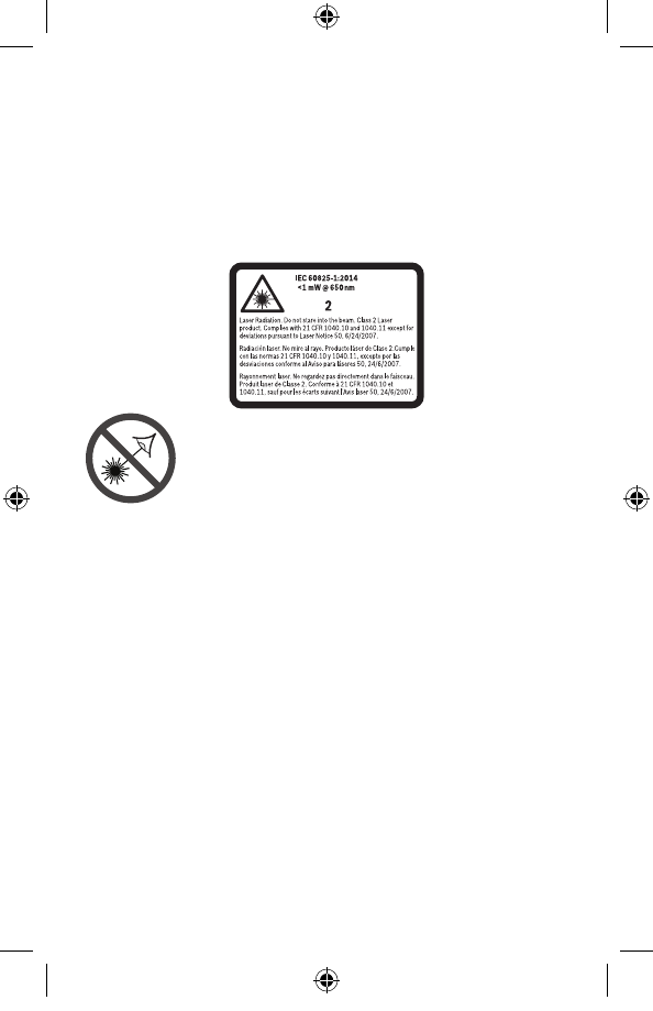
Safety Rules for Laser Tools
The following label is on your laser tool for your safety. AL-
WAYS BE AWARE of its location when using the tool.
DO NOT direct the laser beam at persons or
animals and do not stare into the laser beam
yourself. This tool produces class 2 laser radia-
tion and complies with 21 CFR 1040.10 and
1040.11 except for deviations pursuant to Laser
Notice No. 50, dated June 24, 2007. This can lead to persons
being blinded.
DO NOT place the measuring tool in a position that may
cause anyone to stare into the laser beam intentionally or
unintentionally. Serious eye injury could result.
Never aim the beam at a workpiece with a reflective surface.
Bright shiny reflective sheet steel or similar reflective
surfaces are not recommended for laser use. Reflective
surfaces could direct the beam back towards the operator.
DO NOT operate the measuring tool around children or
allow children to operate the measuring tool. Serious eye
injury could result.
ALWAYS: Make sure that any bystanders in the vicinity of
use are made aware of the dangers of looking directly into
the measuring tool.
Do not use the measuring tool to photograph any
people or animals, as this involves the laser beam being
continuously switched on. You could blind somebody or
2610049010 10-17 GLM400C.indd 12 11/3/17 1:09 PM

13
cause accidents or eye damage with the laser beam switched
on.
DO NOT remove or deface any warning or caution labels.
Removing labels increases the risk of exposure to laser
radiation.
Do not use the measuring tool if the display glass is visibly
damaged (e.g. cracks in the surface, etc.). This poses a risk
of injury.
DO NOT operate the measuring tool in combustible areas
such as in the presence of flammable liquids, gases or dust.
Use of controls or adjustments or performance of
procedures other than those specified herein may result in
hazardous radiation exposure.
Do not use the laser viewing glasses as sun glasses or in
traffic. The laser viewing glasses do not afford complete UV
protection and reduce color perception.
DO NOT leave measuring tool “ON” unattended in any
operation mode.
ALWAYS turn the measuring tool “OFF” when not in use.
Leaving the measuring tool “ON” increases the risk of someone
inadvertently staring into the laser beam.
ALWAYS position the measuring tool securely. Damage to
the measuring tool and/or serious injury to the user could result
if the measuring tool falls.
Take care to recognize the accuracy and range of the
device. Measurement may not be accurate if used beyond the
rated range of the device.
ALWAYS use only the accessories that are recommended
by the manufacturer of your measuring tool. Use of
accessories that have been designed for use with other
measuring tools could result in serious injury.
DO NOT use this measuring tool for any purpose other
than those outlined in this manual. This could result in
serious injury.
ALWAYS remove the batteries when cleaning the laser light
aperture and laser lens.
DO NOT disassemble the measuring tool. There are no
user serviceable parts inside. Disassembling the laser
2610049010 10-17 GLM400C.indd 13 11/3/17 1:09 PM
14
will void all warranties on the product. Do not modify the
product in any way. Modifying the measuring tool may result
in hazardous laser radiation exposure.
Repair and servicing must always be performed by a
qualified repair facility. Repairs performed by unqualified
personnel could result in serious injury.
Bluetooth®
Do not use the laser measure with Bluetooth® in the
vicinity of gas stations, chemical plants, areas where
there is danger of explosion and areas subject to blast-
ing. Do not use the laser measure with Bluetooth® in air-
planes. Do not use the laser measure with Bluetooth® in
the vicinity of medical devices. Avoid operation in the
direct vicinity of the human body over longer periods
of time. When using the laser measure with Bluetooth®,
interference with other devices and systems, airplanes
and medical devices (e.g., cardiac pacemakers, hearing
aids) may occur.
The Bluetooth® word mark and logos are registered trade-
marks owned by Bluetooth SIG, Inc. and any use of such
marks by Robert Bosch Tool Corporation is under license.
FCC Caution
The manufacturer is not responsible for radio interfer-
ence caused by unauthorized modifications to this equip-
ment. Such modifications could void the user’s authority
to operate the equipment.
This device complies with Part 15 of the FCC Rules. Op-
eration is subject to the following two conditions:
1) This device may not cause harmful interference, and
2) This device must accept any interference received, in-
cluding interference that may cause undesired opera-
tion.
NOTE! This equipment has been tested and found to com-
ply with the limits for a Class B digital devices, pursuant to
Part 15 of the FCC rules. These limits are designed to pro-
2610049010 10-17 GLM400C.indd 14 11/3/17 1:09 PM

15
vide reasonable protection against harmful interference
in a residential installation. This equipment generates
uses and can radiate radio frequency energy and, if not
installed and used in accordance with the instructions,
may cause harmful interference to radio communications.
However, there is no guarantee that interference will not
occur in a particular installation. If this equipment does
cause harmful interference to radio or television recep-
tion, which can be determined by turning the equipment
off and on, the user is encouraged to try to correct the
interference by one or more of the following measures:
• Reorientorrelocatethereceivingantenna.
• Increasetheseparation betweentheequipment and
receiver.
• Connecttheequipmentintoanoutletonacircuitdif-
ferent from that to which the receiver is connected.
• Consultthedealeroranexperiencedradio/TVtechni-
cian for help.
“ExposuretoRadioFrequency(RF)Signals:Thewireless
device is a radio transmitter and receiver. It is designed
andmanufacturednottoexceedtheemissionlimitforex-
posure to radio frequency (RF) energy set by the Ministry
of Health (Canada), Safety Code 6. These limits are part
of comprehensive guidelines and established permitted
levels of RF energy for the general population.
These guidelines are based on the safety standards previ-
ously set by international standard bodies. These stan-
dards include a substantial safety margin designed to
assure the safety of all persons, regardless of age and
health.
This device and its antenna must not be co-located or op-
erating in conjunction with any other antenna or transmit-
ter.
This device has been shown to be capable of compli-
ance for localized specific absorption rate (SAR) for un-
controlled environment / general public exposure limits
specicinANSI/IEEEC95.1-1992andhadbeentestedin
accordance with the measurement procedures specified
in IEEE 1528-2003.”
2610049010 10-17 GLM400C.indd 15 11/3/17 1:09 PM
16
The measuring tool is intended for measuring distances,
lengths, heights, clearances and inclines, and for calculating
areas and volumes.
The measuring results can be transmitted to other devices via
Bluetooth®.
Intended Use
2610049010 10-17 GLM400C.indd 16 11/3/17 1:09 PM
17
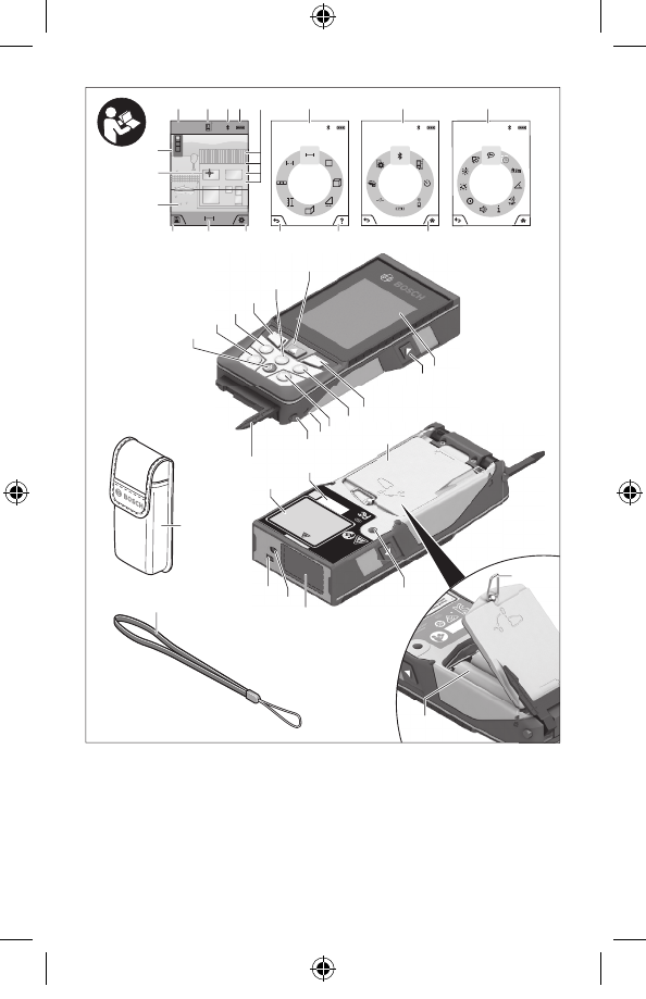
Features
The numbering of the product features shown refers to the
illustration of the measuring tool on the graphic page.
1 Display
2 Measuring button
3 Soft key
4 Plus button
(Select to the right)
5 Zoom button
6 Carrying strap lug
7 Measuring pin release
button
8 Measuring pin
9 On/Off/Clear button
10 Digital Viewfinder Button
11 Minus button
(Select to the left)
12 Soft key
13 Function button
14 Laser warning label
15 Serial number
16 Battery lid
17 1/4” Tripod socket
18 Laser beam outlet
19 Digital viewfinder
20 Reception lens
21 Twist lock
22 Batteries
23 Protective pouch
24 Carrying strap
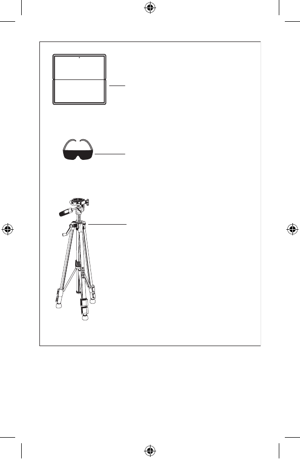
25 Laser target plate*
26 Laser viewing glasses*
27 Tripod*
Display Elements
a Result line
b Target indicator (crosshair)
c Display tilt angle
d Date/time
e Measurement reference
level
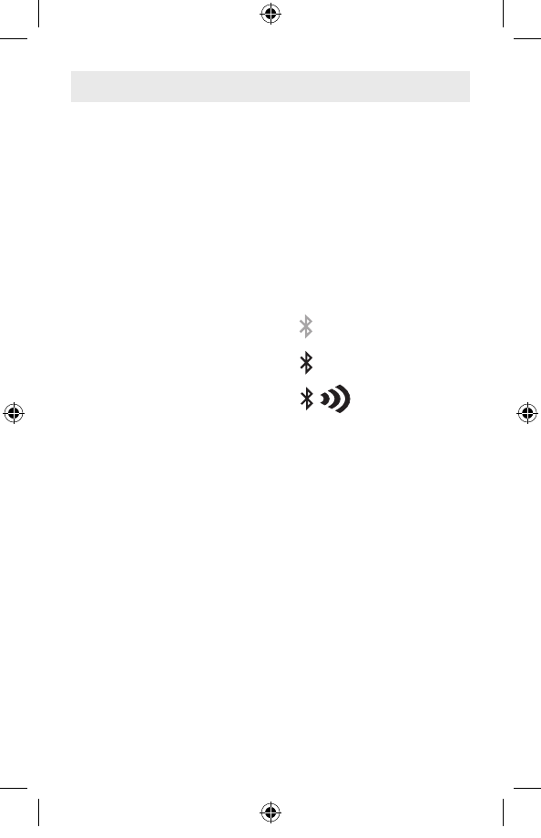
f Connection status
Bluetooth®
not activated
Bluetooth®
activated
Bluetooth®
Connected
g Battery indicator
h Measured-value lines
i Settings (soft key)
j Selected measuring
function
k Internal memory (soft key)
l Help screen
m Back (soft key)
n Home screen (soft key)
o Tool settings
2610049010 10-17 GLM400C.indd 17 11/3/17 1:09 PM

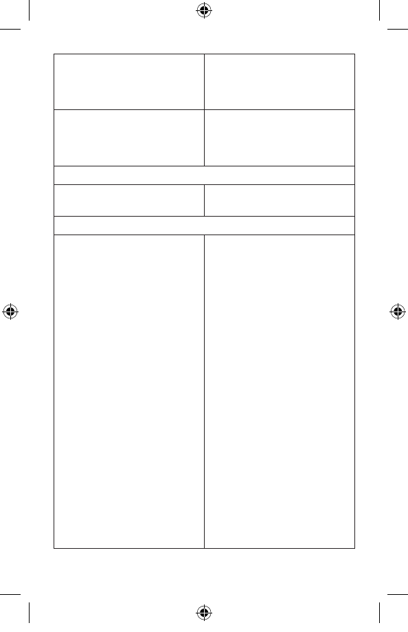
18
Digital Laser Measure GLM400C
Measuring range (typical) 2 in - 400 ft (0.05 –122 mA))
Measuring range (typical,
unfavorable conditions) 196 ft (60 mB))
Measuring accuracy (typical) ±1/16 in (±1.5 mmA))
Measuring accuracy (typical,
unfavorable conditions) ±1/10 in (±3 mmB))
Lowest indication unit 1/32 in (0.5 mm)
Indirect Distance Measurement and Vial
- Measuring range 0°–360° (4x90°)
Gradient measurement
- Measuring range 0°–360° (4x90°)
- Measuring accuracy (typical) ±0.2°C)/D)/H)
- Lowest indication unit 0.1°
Operating temperature +14° F to 113° F (-10° C to +45° C)E)
Storage temperature -4° F to 158° F (-20° C to +70° C)
Relative air humidity, max. 90 %
Laser class 2
Laser type 650 nm, <1mW
Laser beam diameter at 77° F (25 °C)
- at 32 ft (10 m) distance, approx. .35 in (9 mm)
- at 328 ft (100 m) distance, approx. 3.5 in (90 mm)
Automatic switch-off after approx.
- Laser 20 s
- Measuring Tool AdjustableG)
Weight .46 lb (0.21 kg)
Dimensions 5.5 (6.9) x 2.5 x 1.1 in (142 (176) x 64 x 28 mm)
Batteries 3 x 1.5V (AA)
Degree of Protection IP54 (dust and splash water protected)C)
Technical Data
2610049010 10-17 GLM400C.indd 18 11/3/17 1:09 PM
19
Bluetooth® Bluetooth® (4.1 low-energy)F)
Operating frequency band 2402 – 2480 MHz
A) For measurements from the front edge of the measuring tool, applies to high
reflectivity of the target (e.g. a white-painted wall), weak backlighting and 25°C
operating temperature. In addition, a deviation of ±0,05mm/m must be taken
into account.
B) For measurements from the rear edge of the measuring tool, applies to low
reflectivity of the target (e.g. a dark-painted wall), strong backlighting and – 10°C
to +45°C operating temperature. In addition, a deviation of ±0.15 mm/m must be
taken into account.
C) After calibration at 0° and 90° with an additional pitch error of max. ±0.01°/
degrees up to 45°. The measurement accuracy is related to the 3 orientations
based on the calibration of the inclination (tilt measurement), see picture H.
D) At 25°C operating temperature.
E) In the continuous measurement function, the maximum operating temperature
is +40°C.
F) When using Bluetooth® Low Energy tools, it may not be possible to establish a
connection depending on the model and operating system. Bluetooth® devices
must support the GATT profile.
G) Automatic switch-off of the measuring tool is adjustable after 2, 5, 10 minutes
or never.
H) The left-hand side of the measuring tool serves as the reference level for grade
measurement.
A long battery runtime is achieved by means of energy-saving measures, such
as deactivating the Bluetooth® function when not required, or reducing the display
brightness, etc.
The measuring tool can be clearly identified with the serial number 15 on the type
plate.
2610049010 10-17 GLM400C.indd 19 11/3/17 1:09 PM
20
Assembly
Inserting/Replacing the Batteries
AA alkaline batteries are recommended for the measuring tool.
To open the battery lid, press the latch in the direction of the
arrow and remove the battery lid. Insert the batteries. When
inserting, pay attention to the correct polarity according to the
representation on the inside of the battery compartment.
When the battery symbol appears for the first time on the
display, measurements are still possible for approx. 15 minutes.
When the battery symbol flashes, the batteries must be
replaced; measurements are no longer possible.
Always replace all batteries at the same
time. Only use batteries from one
brand and with the identical capacity.
Remove the batteries from the tool when not using it for
extended periods. When storing for extended periods, the
batteries can corrode and discharge themselves.
Operation
Protect the tool against moisture and
direct sun irradiation.
Do not subject the tool to extreme temperatures or
variations in temperature. As an example, do not leave
it in vehicles for longer periods. In case of large variations
in temperature, allow the tool to adjust to the ambient
temperature before putting it into operation. In case of extreme
temperatures or variations in temperature, the accuracy of the
tool can be impaired.
Avoid heavy impact or falling of the tool.
After heavy exterior
impact on the tool, an accuracy check should always be
carried out before continuing to work (see “Accuracy Check of
the Distance Measurement”, page 36).
DO NOT stare directly at the laser beam
or project the laser beam directly into
the eyes of others. Serious eye injury could result.
2610049010 10-17 GLM400C.indd 20 11/3/17 1:09 PM
21
Do not leave the switched on measuring tool unattended
and switch the tool off after use. Other persons could be
blinded by the laser beam.
Switching On and Off
During work, ensure that the reception lens 20, laser beam
output 18, and digital viewfinder 19 are not closed off or
covered, otherwise correct measurement will not be possible.
– To switch on the measuring tool and the laser, briefly press
the On/Off button 9 [ ], front or side measuring button 2 [ ].
Do not point the laser beam at persons or animals and
do not look into the laser beam yourself, not even from a
large distance.
– To switch off the laser, press the On/Off button 9 [ ].
– To switch off the digital viewfinder, press the digital
viewfinder button 10.
– To switch off the measuring tool, press and hold the On/Off
button 9 [ ].
The measured values and device settings in the memory are
retained when you switch the tool off.
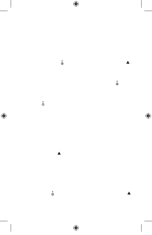
Measuring Procedure
Once switched on, the measuring tool is in the continuous
laser measurement function. For a different measuring
function, press the button 13 [Func]. Select the desired
measuring function with the buttons 4 [+] or the button 11 [–]
(see “Measuring Functions”, page 27). Activate the
measuring function with button 13 [Func] or with the
measuring button 2 [ ].
After switching on, the rear edge of the measuring tool
is preset as the reference level for the measurement. To
change the reference level, see “Selecting the Reference
Level”, page 22.
Place the measuring tool against the desired starting point of
the measurement (e.g. a wall).
Note: If the measuring tool has been switched on using the
On/Off button 9 [ ], briefly press the measuring button 2 [ ]
to switch the laser on.
2610049010 10-17 GLM400C.indd 21 11/3/17 1:09 PM
22
To initiate the measurement, briefly press the measuring
button 2 [ ]. Then the laser beam is switched off. For a
further measurement, repeat this process.
With the laser beam continuously switched on and in the the
continuous measurement function, measurement will begin
after the measuring button 2 [ ] is pressed for the first time.
Do not point the laser beam at persons or animals and
do not look into the laser beam yourself, not even from a
large distance.
Note: The measured value typically appears within 0.5 s and
no later than approx. 4 s. The duration of the measurement
depends on the distance, the lighting conditions and the
reflective properties of the target surface. Upon completion of
the measurement, the laser beam is automatically switched
off. The continuously switched-on laser beam is not switched
off after the measurement (see “Continuous Laser Beam”,
page 23).
Selecting the Reference Level (see figure A)
You can choose between four different reference levels for
the measurement:
– the rear measuring-tool edge (e.g. when measuring onward
from a wall),
– the tip of the 180° folded-out measuring pin 8 (e.g. when
measuring from a corner),
– the front measuring-tool edge (e.g. when measuring
onward from a table edge),
– the center of thread 17 (e.g. for tripod measurements).
Folding out and in of the measuring pin 8 by 180° is detected
automatically and the appropriate reference level is
suggested. Confirm the setting by pressing the measuring
button 2 [ ].
Use the soft key 3 [ ] to select the basic settings for the
measuring tool. Use buttons 4 [+] or 11 [–] to select the
reference level and confirm this by pressing button 13 [Func].
The rear edge of the measuring tool is automatically preset
as the reference level every time the measuring tool is
switched on.
2610049010 10-17 GLM400C.indd 22 11/3/17 1:09 PM
23
Permanent Laser Beam
If necessary, you can switch the measuring tool to permanent
laser beam operation. To do so, use soft key 3 [ ] to select
the basic settings for the measuring tool. Use buttons 4 [+] or
11 [–] to select the permanent laser beam and confirm this by
pressing button 13 [Func].
Do not point the laser beam at persons or animals and
do not look into the laser beam yourself, not even from a
large distance.
In this setting, the laser beam remains switched on even
between measurements; measurement simply requires one
brief press of the measuring button 2 [ ].
The permanent laser beam can be switched off again in the
basic settings or automatically when the measuring tool is
switched off.
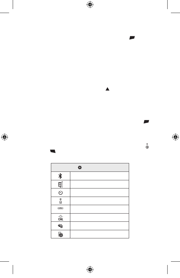
“Settings” Menu
To enter the “settings” menu (i) briefly press soft key 3 [ ] or
press and hold button 13 [Func].
Use button 4 [+] or 11 [–] to select the relevant basic setting
and press button 13 [Func] to select the required setting.
To exit the “settings” menu, press the On/Off button 9 [ ] or
soft key 12 [ ].
Settings
CAL
Bluetooth®
CAL
Reference Level
CAL
Meas Timer
CAL
Permanent Laser
CAL
Tilt Calibration
Viewfinder Calibration
CAL
Memory
CAL
Tool Settings
2610049010 10-17 GLM400C.indd 23 11/3/17 1:09 PM
24
Timer Function
The timer function is useful when measuring in hard-to-reach
areas, for example, or when the measuring tool should be
kept stationary during measurement.
Select the timer function in the settings. Select the required
time period between triggering the timer and starting
measurement and confirm by pressing the measuring button
2 [ ] or button 13 [Func].
Next, press the measuring button 2 [ ] to switch on the laser
beam and focus on the target. Press the measuring button
2 [ ] once more to start the measurement. The measurement
will begin after the set time period has expired. The measured
value is displayed in the result line a.
The time period between triggering the timer and starting
measurement is displayed in the status bar at the top.
Continuous measurement and minimum/maximum
measurement are not possible with the timer function
enabled.
The timer remains enabled until the measuring tool is
switched off or until the timer is switched off in the menu
“settings”.
Digital Viewfinder
To switch on the digital viewfinder 19, press the digital
viewfinder button 10.
The digital viewfinder 19 is optimized for the detection of the
laser point from a distance and therefore has a small visual
field.
Optimizing visibility of the laser beam
Especially when using the measuring tool outdoors, in
sunlight and also over long distances indoors, it may be that
the laser point is not visible. The visibility of the laser point/
measuring target can be improved additionally to switching on
the camera by:
– Setting the display brightness (tool settings)
– Using the zoom by pressing button 5
2610049010 10-17 GLM400C.indd 24 11/3/17 1:09 PM
25
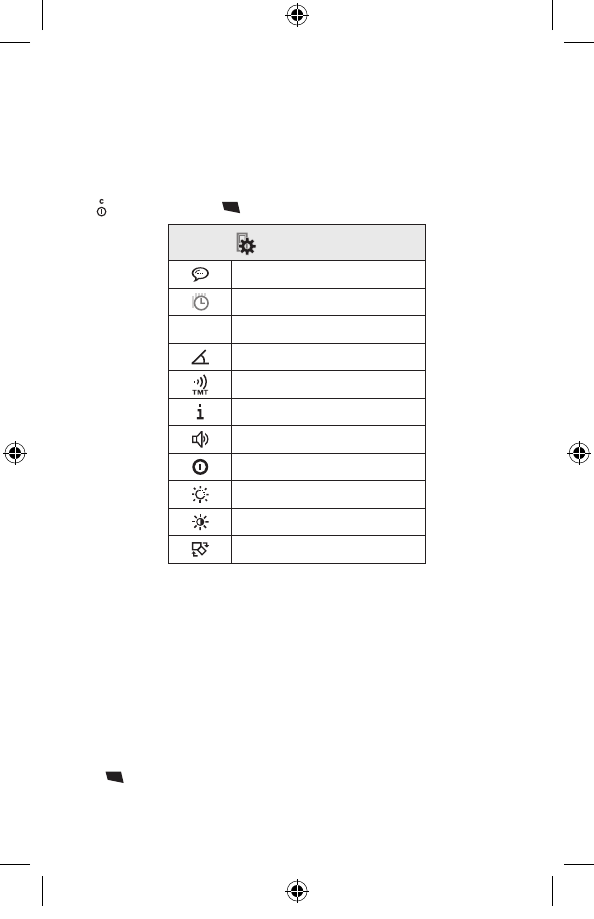
“Tool Settings” Menu
Select the menu “Tool Settings” in the menu “Settings”.
Use button 4 [+] or 11 [–] to select the desired tool setting
and confirm with button 13 [Func]. Select the desired tool
setting.
To exit the “Tool” menu (o), press the On/Off/Clear button
9 [ ] or soft key 12 [ ].
Tool Settings
Language
Time & Date
ft/m Measurement Unit
Angle Unit
TrackMyTools
Tool Information
Audio Signals
Shutdown Time
Dimming
Brightness
Auto Rotate
Setting the language
Select the language in the basic settings (general settings).
Set the required language and confirm by pressing button
13 [Func] or button 2 (measuring).
Setting the date and time
Select the date and time in the basic settings (general
settings).
Set the date and time and confirm by pressing soft key
12 [ ].
2610049010 10-17 GLM400C.indd 25 11/3/17 1:09 PM
26
Changing the Unit of Measure
Select the “Measurement unit” in the tool settings.
Unit of measure “in” (inches) is set by default.
Set the required unit of measure and confirm by pressing
button 13 [Func].
To exit the menu item, press the On/Off/Clear button 9 [ ] or
soft key 3 [ ]. The selected setting remains saved after you
switch off the measuring tool.
Changing the Angle Unit
Select the “Angle unit” in the tool settings.
Angle unit “°” (grade) is set by default.
Set the required angle unit and confirm by pressing button
13 [Func].
To exit the menu item, press the On/Off/Clear button 9 [ ] or
soft key 3 [ ]. The selected setting remains saved after you
switch off the measuring tool.
TrackMyTools
Select “TrackMyTools” in the tool settings.
Confirm the setting by pressing button 13 [Func].
An initial activation is required. Data transmission is only
possible with the corresponding app or the corresponding PC
program.
After exchanging the batteries, the tool has to be switched on
shortly to re-activate TrackMyTools.
TrackMyTools can be disabled at any time.
Display Illumination
Select the display illumination in the basic settings (general
settings).
The display illumination is continuously switched on. When
no button is pressed, the display illumination is dimmed after
approx. 30 seconds to preserve the batteries.
The time until start of dimming is adjustable (tool settings).
The brightness of the display can be adjusted to the
surrounding conditions in multiple increments (general
settings).
2610049010 10-17 GLM400C.indd 26 11/3/17 1:09 PM
27
Measuring Functions
Note: Integrated Help Function
Help in the form of an animation is stored in the measuring tool
for each measuring function. To do so, select button 13 [Func],
buttons 4 [+] or 11 [–] and then soft key 3
[ ]
.
The animation shows you the detailed procedure for the selected
measuring function. The animation can be stopped and started
again at any time. You can scroll forward and back with buttons
4 [+] or 11 [–].
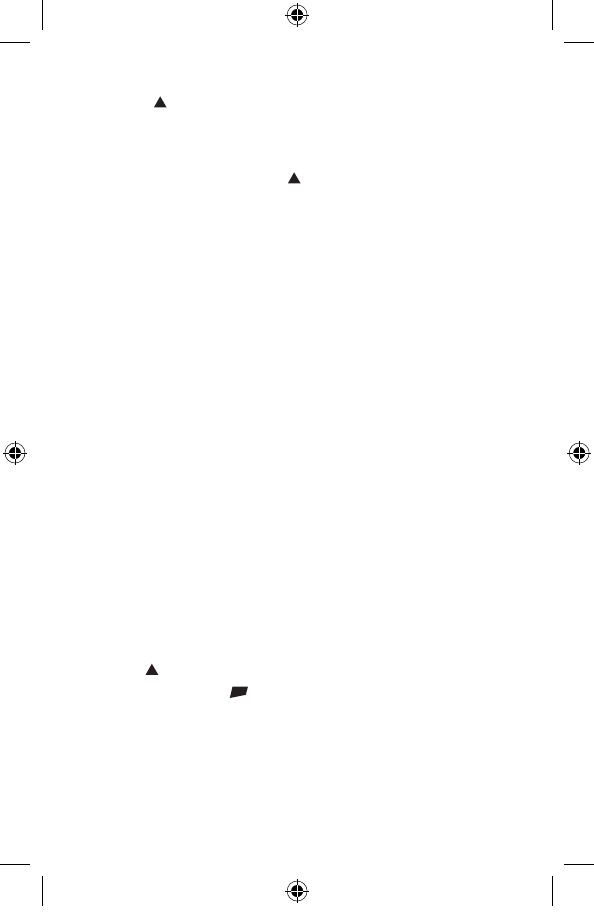
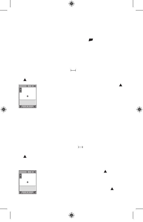
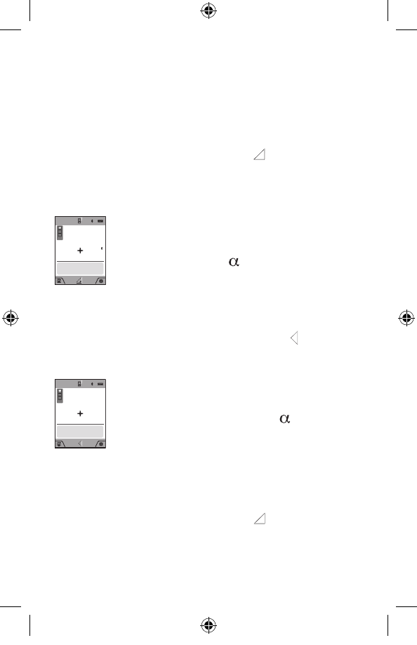
Length Measurement
Select the length measurement .
To switch on the laser beam, briefly press the measuring button
2
[ ]
.
09.06.2017
13:20:23
0.0º
76´01˝⁄
45´08˝
60´10˝⅝
30´05˝
To measure, briefly press the measuring button 2
[ ]
.
The measured value will be shown at the bottom of
the display.
Repeat the above-mentioned steps for each
subsequent measurement. The last measured value
is at the bottom of the display, the penultimate
measured value is above it, and so on.
Continuous Measurement (Tracking)
For continuous measurements, the measuring tool can be moved
relative to the target, whereby the measuring value is updated
approx. every 0.5 seconds. In this manner, as an example, you
can move a certain distance away from a wall, while the actual
distance can always be read.
Select the continuous measurement .
To switch on the laser beam, briefly press the measuring button
2
[ ]
.
Move the measuring tool until the required distance value is
indicated in the bottom of the display.
09.06.2017
13:20:23
0.0º
max
min
30´05˝
76´01˝⁄
76´01˝⁄
Briefly pressing the measuring button 2
[ ]
interrupts
the continuous measurement. The current measured
value will be shown at the bottom of the display. The
maximum and minimum measured value appear
above it. Pressing the measuring button 2
[ ]
once
more restarts the continuous measurement.
Continuous measurement automatically switches off after 5 mins.
2610049010 10-17 GLM400C.indd 27 11/3/17 1:09 PM
28
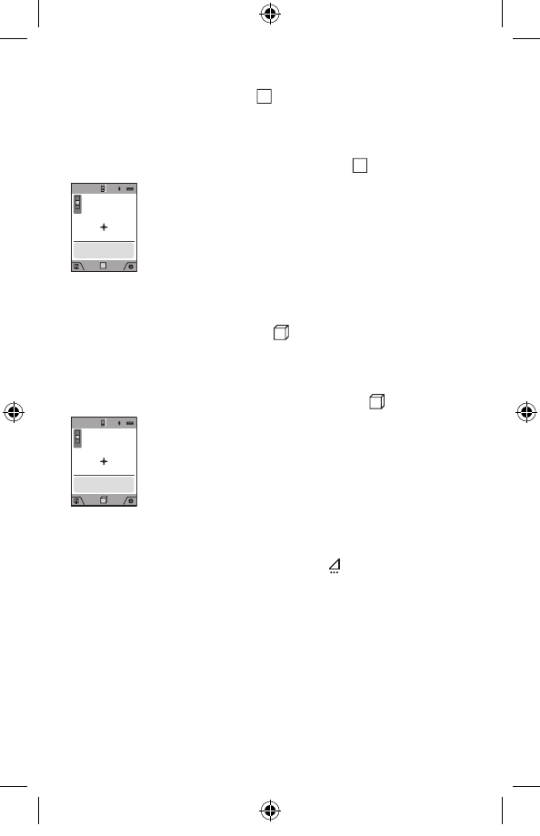
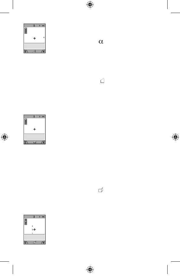
Area Measurement
Select the area measurement .
Then measure the width and length one after the other as with
a length measurement. The laser beam remains switched on
between the two measurements. The distance to be measured
flashes in the indicator for area measurement .
09.06.2017
13:20:23
0.0º
728.167 ft
2
25´00˝
29´02˝
The first measured value is shown at the top of the
display.
After the second measurement has been completed,
the area will be automatically calculated and
displayed. The end result is shown at the bottom of
the display, while the individual measured values are
shown above it.
Volume Measurement
Select the volume measurement .
Then measure the width, length and depth one after the other as
with a length measurement. The laser beam remains switched on
between the three measurements. The distance to be measured
flashes in the indicator for volume measurement .
09.06.2017
13:20:23
0.0º 25´00˝
29´02˝
15´03˝
11124.1 ft
3
The first measured value is shown at the top of the
display.
After the third measurement has been completed,
the volume will be automatically calculated and
displayed. The end result is shown at the bottom of
the display, while the individual measured values are
shown above it.
Indirect Distance Measurement
Select the indirect distance measurement .
There are four measuring functions available for the indirect
distance measurement, each of which is capable of determining
different distances.
The indirect distance measurement is used to measure distances
that cannot be measured directly because an obstacle would
obstruct the laser beam or no target surface is available as a
reflector. This measuring procedure can only be used in vertical
direction. Any deviation in horizontal direction leads to measuring
errors.
Note: Indirect distance measurement is always less accurate
2610049010 10-17 GLM400C.indd 28 11/3/17 1:09 PM
29
than direct distance measurement. Depending on application,
greater measuring errors are possible than with direct distance
measurement. To improve the measuring accuracy, we recommend
using a tripod (accessory).
The laser beam remains switched on between the individual
measurements.
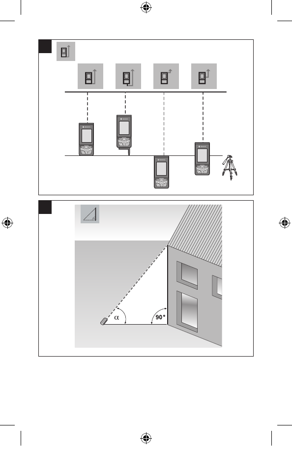
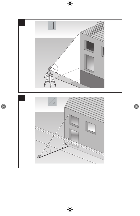
a) Indirect height measurement (see figure B)
Select the indirect height measurement .
Ensure that the measuring tool is at the same height as the
lower measuring point. Then tilt the measuring tool around the
reference level and measure the distance “1” as for a length
measurement (displayed as a red line).
09.06.2017
13:20:23
45º 121´09˝¼
45.0
86´01˝¼
Upon completion of the measurement, the result
for the sought distance “X” is displayed in the
result line a. The measuring values for the distance
“1” and the angle “ ” are displayed in the
measured-value lines h.
b) Double indirect height measurement (see figure C)
The measuring tool can indirectly measure all distances, which
lie in the vertical level of the measuring tool.
Select the double indirect height measurement .
Measure distances “1” and “2” in this sequence as for a
length measurement.
09.06.2017
13:20:23
º
30º
107´09˝⅜
160´04˝
184´09˝
35.5
Upon completion of the measurement, the result
for the sought distance “X” is displayed in the
result line a. The measuring values for the
distances “1”, “2” and the angle “ ” are displayed
in the measured-value lines h.
Pay attention that the reference plane of the
measurement (e.g. the rear edge of the measuring tool)
remains exactly at the same location for all individual
measurements within a measuring sequence.
c) Indirect length measurement (see figure D)
Select the indirect length measurement .
Pay attention that the measuring tool is positioned at the same
height as the sought measuring point. Now, tilt the measuring
tool around the reference plane and measure distance “1” as
for a length measurement.
2610049010 10-17 GLM400C.indd 29 11/3/17 1:09 PM
30
09.06.2017
13:20:23
60º
48´06˝
60.0
24´09˝⅜
Upon completion of the measurement, the result
for the sought distance “X” is displayed in the
result line a. The measuring values for the distance
“1” and the angle “ ” are displayed in the
measured-value lines h.
d) Trapezium Measurement (see figure E)
The trapezium measurement can be used to determine the
length of a roof slope, for example.
Select the trapezium measurement .
Measure distances “1”, “2” and “3” in this sequence with a
length measurement. Pay attention that the measurement of
distance “3” starts exactly at the end point of distance “1” and
that a right angle exists between distances “1” and “2” as well
as between “1” and “3”.
09.06.2017
13:20:23
60º
11´10˝⅝
8´00˝¾
15´11˝¾
14´04˝½
Upon completion of the last measurement, the
result for the sought distance “E” is displayed in
the result line a. The individual measured values
are displayed in the measured-value lines h.
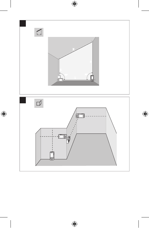
Wall Area Measurement (see figure F)
The wall area measurement is used to determine the sum of
several individual surfaces with a common height.
In the illustrated example, the total area of several walls should
be determined, which have the same ceiling height H, but
different lengths L.
Select the wall area measurement .
Measure the ceiling height H as with a length measurement.
The measured value is displayed in the top measured-value
line. The laser remains switched on.
09.06.2017
13:20:23
0.0º
8´02˝⅜
41´02˝⅜
12´09˝½
103´00˝
Then measure the length L1 of the first wall. The
surface is automatically calculated and displayed
in the result line a. The last length measured value
is in the bottom measured-value line h. The laser
remains switched on.
2610049010 10-17 GLM400C.indd 30 11/3/17 1:09 PM
31
Now measure the length L2 of the second wall. The individual
measured value displayed in the measured-value line h is
added to the length L1. The sum of the two lengths (displayed
in the bottom measured-value line h) is multiplied by the saved
height H. The total surface value is displayed in the result
line a.
You can measure any number of lengths LX, which will be
automatically added and multiplied by the height H.
The requirement for a correct area calculation is that the first
measured length (for example the ceiling height H) is identical
for all sub-areas.
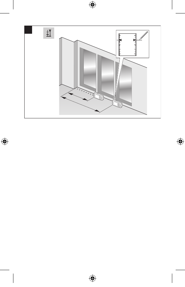
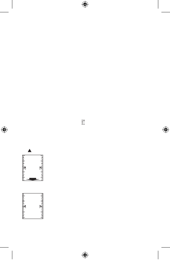
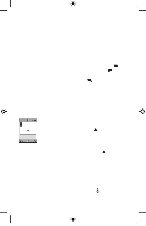
Stake out function (see figure G)
The stake out function repeatedly measures a defined length
(distance). These lengths can be transferred to a surface,
for example to enable material to be cut into pieces of equal
lengths or to install stud walls in a drywall construction. The
minimum adjustable length is 3.2 ft (0,1m), the maximum
adjustable length is 164 ft (50m).
Select the stake out function .
Set the desired length. Using button 13 [Func] select the
corresponding digit/position and change the value with button
4 [+] or button 11 [–].
Begin the stake out function by pressing the measuring button
2 [ ] and slowly move away from the starting point.
0´08˝
1´04˝
1
0.5x
The measuring tool continuously measures the
distance to the starting point. The defined length
and the current measured value are thereby
displayed. The lower or upper arrow displays the
shortest distance to the next or last marking.
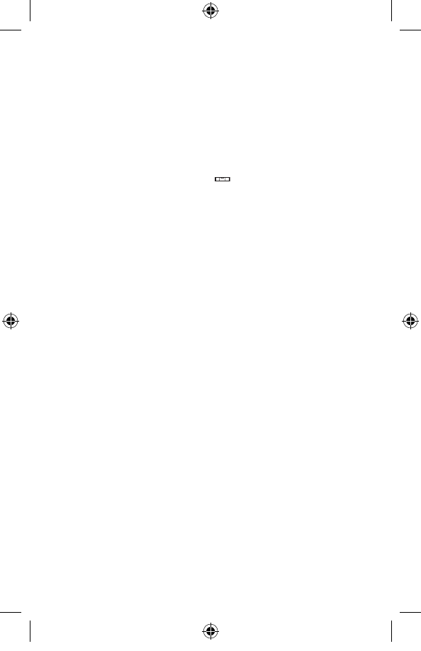
Note: The continuous measuring enables you to set a
measured value as a defined length by pressing the button 3.
1´04˝
1´04˝1x
The left factor specifies how many times the
defined length has already been reached. The
green arrows on either side of the display indicate
the reaching of a length for marking purposes.
Red arrows or a red label indicate the actual value
if the reference value is outside the display.
2610049010 10-17 GLM400C.indd 31 11/3/17 1:09 PM
32
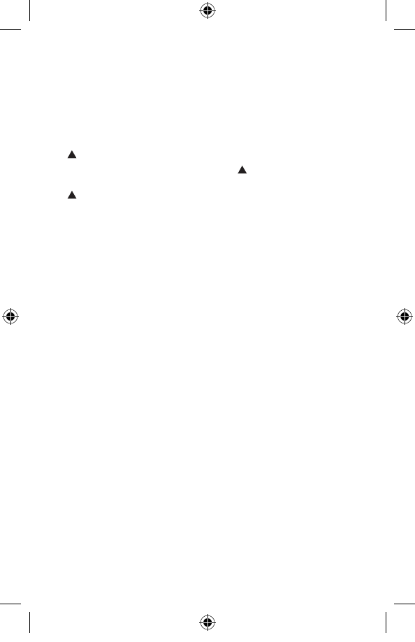
Gradient Measurement/Digital Spirit Level
Select the inclination measurement/digital spirit level .
The measuring tool automatically switches between two
states.
1° 2° 3°
The digital spirit level is used to check the
horizontal or vertical alignment of an object (e.g.
washing machine, refrigerator, etc.). When the
inclination 3° exceeds, the ball in the display lights
red.
88.0°
Gradient measurement is used to measure a slope
or incline (e.g. of stairs, railings, when fitting
furniture, laying pipes, etc.). The left-hand side of
the measuring tool serves as the reference level
for grade measurement. If the display flashes
during measurement, the measuring tool has been
tipped too heavily to the side.
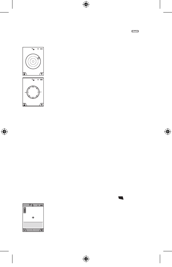
Memory Functions
The value or end result of each completed measurement is
automatically saved.
Tip: You can save your measurement as a photo for reference.
The following information is printed on the photo:
– Measuring result
– Measuring function used
– Reference
– Date and time
– Tilt angle (only with spirit level switched on).
Memory value display
A maximum of 50 values can be retrieved (measured values or
photos with measured values.
Select the memory function using soft key 12 [ ].
09.06.2017
13:20:23
30º
76´01˝⁄
44
30´05˝
45´08˝
60´10˝⅝
The number of the memory value is shown at the
top of the display, the corresponding memory
value is shown at the bottom and the corresponding
measuring function is shown on the left.
Press button 4 [+] to browse forwards through the
saved values.
2610049010 10-17 GLM400C.indd 32 11/3/17 1:09 PM
33
Press button 11 [–] to browse backwards through the saved
values.
If there is no value available in the memory, “0.000” is shown
at the bottom of the display and “0” at the top.
The oldest value is located in position 1 in the memory, while
the newest value is in position 50 (when 50 memory values are
available). When a further value is saved, the oldest value in
the memory is always deleted.
Deleting the Memory
To delete the content of the memory, press soft key 12 [ ] and
then, as many times as required, press soft key 3 [ ].
To delete all values stored in the memory, the function can be
used. Confirm by pressing soft key 12 [ ].
Adding/Subtracting Values
Measured values or end results can be added or subtracted.
Adding Values
The following example describes the addition of areas:
Measure an area as described in section “Area Measurement”,
see page 28.
2
09.06.2017
13:20:23
0.0º
185 ft
2
2
168 ft
17 ft
+
Press the button 4 [+]. The calculated area and the
symbol “+” will be displayed.
Press the measuring button 2 [ ] to start another
area measurement. Measure the area as described
in section “Area Measurement”, see page 28. Once
the second measurement is completed, the result
of the second area measurement is displayed below. To show
the end result, press the measurement button 2 [ ] once more.
Note: With a length measurement, the end result is displayed
immediately.
Subtracting Values
To subtract values, press button 11 [–]. The subsequent steps
are the same as for “Adding Values”.
Deleting Measured Values
Briefly pressing the On/Off/Clear button 9 [ ] will delete the
last measured value in all measuring functions.
2610049010 10-17 GLM400C.indd 33 11/3/17 1:09 PM

34
Bluetooth® Interface
Data Transmission to other Devices
The measuring tool is equipped with a Bluetooth® module,
which enables data transmission via radio technology to
certain mobile terminals/devices with a Bluetooth® interface
(e.g., smartphones, tablets).
For information on the necessary system requirements for a
Bluetooth® connection, please refer to the Bosch website at
www.bosch-pt.com
Further information can be found on the Bosch product
page.
For data transmission via Bluetooth®, time delays between
mobile terminal/device and measuring tool may occur. This
can be possible due to the distance between both devices or
the object being measured.
Activating the Bluetooth® Interface for Data Transmission
to a Mobile Terminal/Device
The Bluetooth® interface is activated in the basic settings. To
activate the Bluetooth® signal, press button 4 [+]. Ensure that
the Bluetooth® interface is activated on your mobile end device.
The special Bosch “Measuring Master” app is available to
extend the range of functions of the mobile end device and to
make data easier to process. You can download this from the
store for your end device type.
The connection between mobile terminal/device and
measuring tool is established after the Bosch application has
started. If multiple active measuring tools are found, select the
appropriate measuring tool using the serial number.
The connection status, as well as the active connection (f), are
shown in the display 1 of the measuring tool.
Deactivating the Bluetooth® Interface
The Bluetooth® connection is deactivated in the basic settings.
To deactivate the Bluetooth® signal, press button 11 [–] or
switch off the measuring tool.
2610049010 10-17 GLM400C.indd 34 11/3/17 1:09 PM

35
Working Advice
Further information can be found on the Bosch product
page.
The measuring tool is equipped with a radio interface.
Local operating restrictions, e.g. in airplanes or hospitals,
are to be observed.
General Information
The reception lens 20, the laser beam output 18 and the digital
viewfinder 19 must not be covered during measurement.
The measuring tool must not be moved while taking a
measurement. Therefore, place the measuring tool, as far as
this is possible, against or on a firm stop or supporting surface.
Influence Effects on the Measuring Range
The measuring range depends on the lighting conditions
and the reflective properties of the target surface. For better
visibility of the laser beam in strong extraneous light, use the
integrated digital viewfinder 19, the laser viewing glasses 26
(accessory) and the laser target plate 25 (accessory) or shade
the target area.
Influence Effects on the Measuring Result
Due to physical effects, faulty measurements cannot be
excluded when measuring on different surfaces. Included here
are:
– Transparent surfaces (e.g., glass, water),
– Reflecting surfaces (e.g., polished metal, glass),
– Porous surfaces (e.g. insulation materials),
– Structured surfaces (e.g., roughcast, natural stone).
If required, use the laser target plate 25 (accessory) on these
surfaces.
Furthermore, faulty measurements are also possible when
sighting inclined target surfaces.
Also, air layers with varying temperatures or indirectly received
reflections can affect the measured value.
2610049010 10-17 GLM400C.indd 35 11/3/17 1:09 PM
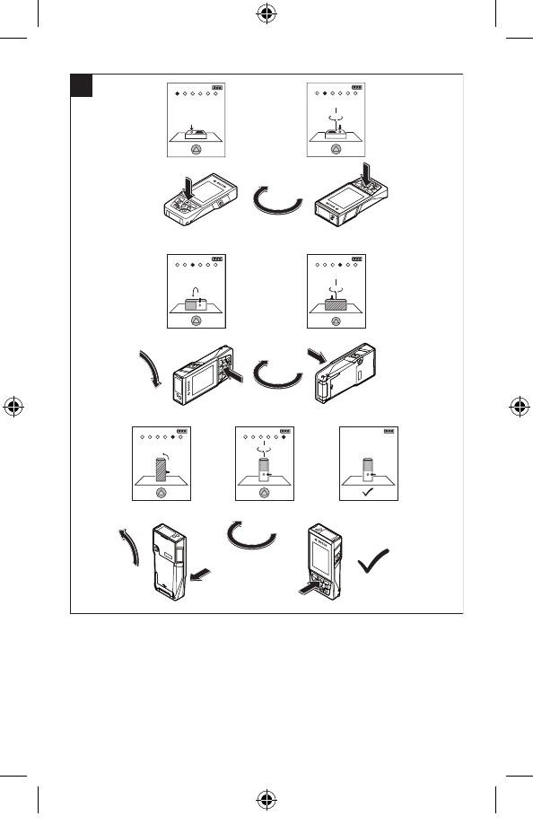
36
Accuracy Check and Calibration of the Grade Measurement
(see figure H)
Regularly check the accuracy of the grade measurement. This
is done by carrying out a reversal measurement. For this, place
the measuring tool on a table and measure the grade.
Turn the measuring tool by 180° and measure the grade again.
The difference of the indicated reading may not exceed by
more than 0.3° (max.).
In the event of larger deviations, you have to recalibrate the
measuring tool. For this, select
CAL
. Follow the instructions on
the display.
After severe temperature changes and impact, we recommend
an accuracy check and, if required, to recalibrate the measuring
tool. After a temperature change, the measuring tool must
acclimate for a while before calibrating.
Accuracy Check of the Distance Measurement
The accuracy of the measuring tool can be checked as follows:
– Select a permanently unchangeable measuring section
which is approx. 9.8 to 32 ft (3 to 10 m) long and which you
know the exact length of (e.g. room width, door opening).
The measurement should be performed under favorable
conditions, i.e. the measuring section should be indoors with
weak backlighting and the target area of the measurement
should be smooth and reflect well (e.g. a white-painted wall).
– Measure the distance 10 times in succession.
The deviation of the individual measurements from the
average value must not exceed ±.07 in (±2 mm) over the
entire measuring section in favorable conditions. Record the
measurements in order to be able to compare the accuracy
at a later date.
2610049010 10-17 GLM400C.indd 36 11/3/17 1:09 PM
37
Checking accuracy and calibrating the target indicator
(crosshair)
Check the accuracy of the alignment of the laser and target
indicator on a regular basis.
– Select a bright area at least 10 m away with as little
illumination as possible as the target.
– Check whether the laser point is inside the target indicator
in the display.
If the laser point is not inside the target indicator, you must
recalibrate the target indicator.
Working with the Tripod (Accessory)
The use of a tripod is particularly necessary for larger distances.
Position the measuring tool with the 1/4” thread 17 onto the
quick-change plate of the tripod 27 or a commercially available
camera tripod. Tighten the measuring tool with the locking
screw of the quick-change plate.
Set the reference level for measurements with a tripod in the
basic settings or by pressing button 3 (thread reference level).
2610049010 10-17 GLM400C.indd 37 11/3/17 1:09 PM
38
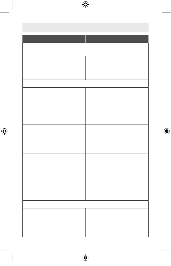
Troubleshooting
Cause Corrective Measure
Temperature warning flashes,
measurement not possible
Measuring tool not within the
temperature range between
+14°F and 113°F ( –10°C
and +45°C).
Wait until the measuring tool
has reached the operating
temperature.
“ERROR” indication in the display
Addition/Subtraction of
measured values with
different units of measure.
Only add/subtract measured
values with the same units of
measure.
The angle between the laser
beam and the target is too
acute.
Enlarge the angle between
the laser beam and the
target.
The target surface reflects
too intensely (e.g. a mirror)
or insufficiently (e.g. black
fabric), or the ambient light
is too bright.
Work with the laser target
plate 25 (accessory).
The laser beam outlet 18,
reception lens 20, and/
or digital viewfinder 19 are
misted up (e.g. due to a
rapid temperature change).
Wipe the laser beam outlet
18, the reception lens 20,
and/or digital viewfinder 19
dry using a soft cloth.
Calculated value is greater
than 1 999 999 or smaller
than –999 999in/in2/in3.
Divide calculation into
intermediate steps.
“CAL” and “ERROR” indication in the display
The calibration of the grade
measurement was not
carried out in the correct
sequence or in the correct
positions.
Repeat the calibration
according to the instructions
on the display and in the
operating instructions.
2610049010 10-17 GLM400C.indd 38 11/3/17 1:09 PM
39
The surfaces used for
the calibration were
not accurately aligned
(horizontal or vertical).
Repeat the calibration on a
horizontal or vertical surface;
if required, check the surface
first with a level.
The measuring tool was
moved or tilted while pressing
the button.
Repeat the calibration and
hold the measuring tool in
place while pressing the
button.
Bluetooth® cannot be activated
The battery is too low. Change the measuring tool’s
battery.
No Bluetooth® connection
Failure of the Bluetooth®
connection Switch off and restart
Bluetooth® on the measuring
tool and the mobile device.
Check the application on
your mobile terminal/device.
Check if Bluetooth® is
activated on your measuring
tool and mobile terminal/
device.
Check your mobile terminal/
device for overload.
Reduce the distance
between measuring tool and
your mobile terminal/device.
Avoid obstructions (e.g.,
reinforced concrete, metal
doors) between measuring
tool and your mobile
terminal/device. Observe
clearance to electromagnetic
disturbances (e.g., WLAN
transmitters).
2610049010 10-17 GLM400C.indd 39 11/3/17 1:09 PM
40
Measuring result not plausible
The target surface does not
reflect correctly (e.g. water,
glass).
Cover off the target surface.
Laser beam output 18,
reception lens 20 or digital
viewfinder 19 is covered.
Keep the laser beam output
18, reception lens 20 and
digital viewfinder 19 clear.
Wrong reference level set. Select reference level
that corresponds to
measurement.
Obstruction in path of laser
beam. Laser point must be
completely on target surface.
The measuring tool monitors the correct function
for each measurement. When a defect is
determined, only the symbol shown aside flashes
in the display. In this case, or when the above
mentioned corrective measures cannot correct an
error, have the measuring tool checked by an after-sales
service agent for Bosch power tools.
2610049010 10-17 GLM400C.indd 40 11/3/17 1:09 PM
41
Maintenance and Service
Keep the measuring tool clean at all
times.
Do not immerse the measuring tool into water or other fluids.
Wipe off debris using a moist and soft cloth. Do not use any
cleaning agents or solvents.
Take extra special care when cleaning the reception lens 20,
the laser beam exit opening 18 and the viewfinder 19:
Ensure that there is no lint on the reception lens, the laser
beam exit opening and the digital viewfinder. Clean the
reception lens, the laser beam exit opening and the viewfinder
only with cleaning agents which are also suitable for camera
lenses. Do not attempt to remove dirt from the reception lens,
the laser beam exit opening and the viewfinder using pointed
objects, and do not wipe over the reception lens, the laser
beam exit opening and the viewfinder (risk of scratching).
If the measuring tool should fail despite the care taken in
manufacturing and testing procedures, repair should be
carried out by an authorized after-sales service center for
Bosch power tools. Do not open the measuring tool yourself.
In all correspondence and spare parts orders, please always
include the 10-digit article number given on the type plate of
the measuring tool.
ENVIRONMENT PROTECTION
Recycle raw materials and batteries instead of
disposing of waste. The unit, accessories,
packaging and used batteries should be sorted for
environmentally friendly recycling in accordance with
the latest regulations.
2610049010 10-17 GLM400C.indd 41 11/3/17 1:09 PM
42
Robert Bosch Tool Corporation (“Seller”) warrants to the original
purchaser only, that all Bosch lasers and measuring tools will
be free from defects in material or workmanship for a period of
one (1) year from date of purchase. Bosch will extend warranty
coverage to two (2) years when you register your product within
eight (8) weeks after date of purchase. Product registration
card must be complete and mailed to Bosch (postmarked
within eight weeks after date of purchase), or you may register
on-line at www.boschtools.com/Service/ProductRegistration. If
you choose not to register your product, a one (1) year limited
warranty will apply to your product.
30 Day Money Back Refund or Replacement -
If you are not completely satisfied with the performance of your
laser and measuring tools, for any reason, you can return it to
your Bosch dealer within 30 days of the date of purchase for
a full refund or replacement. To obtain this 30-Day Refund or
Replacement, your return must be accompanied by the original
receipt for purchase of the laser or optical instrument product. A
maximum of 2 returns per customer will be permitted.
SELLER’S SOLE OBLIGATION AND YOUR EXCLUSIVE
REMEDY under this Limited Warranty and, to the extent
permitted by law, any warranty or condition implied by law, shall
be the repair or replacement of parts, without charge, which are
defective in material or workmanship and which have not been
misused, carelessly handled, or misrepaired by persons other
than Seller or Authorized Service Center. To make a claim under
this Limited Warranty, you must return the complete Bosch laser
or measuring tool, transportation prepaid, to any BOSCH Factory
Service Center or Authorized Service Center. Please include a
dated proof of purchase with your tool. For locations of nearby
service centers, please use our on-line service locator or call
1-877-267-2499.
LIMITED WARRANTY OF BOSCH LASER AND
MEASURING TOOL PRODUCTS
2610049010 10-17 GLM400C.indd 42 11/3/17 1:09 PM

43
THIS WARRANTY PROGRAM DOES NOT APPLY TO
TRIPODS AND RODS. Robert Bosch Tool Corporation
(“Seller”) warrants tripods and leveling rods for a period of one
(1) year from date of purchase.
THIS LIMITED WARRANTY DOES NOT APPLY TO OTHER
ACCESSORY ITEMS AND RELATED ITEMS. THESE ITEMS
RECEIVE A 90 DAY LIMITED WARRANTY.
To make a claim under this Limited Warranty, you must return
the complete product, transportation prepaid. For details to
make a claim under this Limited Warranty please visit www.
boschtools.com or call 1-877-267-2499.
ANY IMPLIED WARRANTIES SHALL BE LIMITED IN
DURATION TO ONE YEAR FROM DATE OF PURCHASE.
SOME STATES IN THE U.S., AND SOME CANADIAN
PROVINCES DO NOT ALLOW LIMITATIONS ON HOW
LONG AN IMPLIED WARRANTY LASTS, SO THE ABOVE
LIMITATION MAY NOT APPLY TO YOU.
IN NO EVENT SHALL SELLER BE LIABLE FOR
ANY INCIDENTAL OR CONSEQUENTIAL DAMAGES
(INCLUDING BUT NOT LIMITED TO LIABILITY FOR LOSS
OF PROFITS) ARISING FROM THE SALE OR USE OF
THIS PRODUCT. SOME STATES IN THE U.S., AND SOME
CANADIAN PROVINCES DO NOT ALLOW THE EXCLUSION
OR LIMITATION OF INCIDENTAL OR CONSEQUENTIAL
DAMAGES, SO THE ABOVE LIMITATION MAY NOT APPLY
TO YOU.
THIS LIMITED WARRANTY GIVES YOU SPECIFIC LEGAL
RIGHTS, AND YOU MAY ALSO HAVE OTHER RIGHTS WHICH
VARY FROM STATE TO STATE IN THE U.S., OR PROVINCE
TO PROVINCE IN CANADA AND FROM COUNTRY TO
COUNTRY.
THIS LIMITED WARRANTY APPLIES ONLY TO PRODUCTS
SOLD WITHIN THE UNITED STATES OF AMERICA, CANADA
AND THE COMMONWEALTH OF PUERTO RICO. FOR
WARRANTY COVERAGE WITHIN OTHER COUNTRIES,
CONTACT YOUR LOCAL BOSCH DEALER OR IMPORTER.
2610049010 10-17 GLM400C.indd 43 11/3/17 1:09 PM