Robertshaw Controls d b a Invensys Home Control Systems EMSG RF Intelliway Gateway User Manual TD2002 EVX
Robertshaw Controls Company d/b/a Invensys Home Control Systems RF Intelliway Gateway TD2002 EVX
User Manual
TD2002-EVX COPYRIGHT© 2002 INVENYS HOME CONTROL SYSTEMS 8/5/02
EMSG
Intelliway RF Gateway
General Instructions
Introduction
The Intelliway RF Gateway is a high performance
wireless broadband server that is a central part of
the Invensys GoodWatts system.
In addition to basic product description, this document
provides specifications and specific instructions for setup.
Note: This equipment has been tested and found to
comply with the limits for a Class B digital device,
pursuant to Part 15 of the FCC Rules. These limits are
designed to provide reasonable protection against
harmful interference in a residential installation. This
equipment generates, uses and can radiate radio
frequency energy and, if not installed and used in
accordance with the instructions, may cause harmful
interference to radio communications. However, there is
no guarantee that interference will not occur in a
particular installation. If this equipment does cause
harmful interference to radio or television reception,
which can be determined by turning the equipment off
and on, the user is encouraged to try to correct the
interference by one or more of the following measures:
– Reorient or relocate the receiving antenna.
– Increase the separation between the equipment and
receiver.
– Connect the equipment into an outlet on a circuit
different from that to which the receiver is
connected.
– Consult the dealer or an experienced radio/TV
technician for help.
Caution: This equipment is authorized for use under the
United States Federal Communication Commission Rules
and Regulations, Code of Federal Regulations Chapter 47
part 15 and must be installed in accordance with the
instructions provided in this document. Failure to install
or operate this equipment as instructed in this document
could void the user’s authority to operate the equipment.
This equipment contains no user serviceable parts. Any
modification or repairs to the internal components or to
the antenna configuration of the equipment without the
express written consent of Invensys Home Control
Systems could void the user's authority to operate the
equipment.
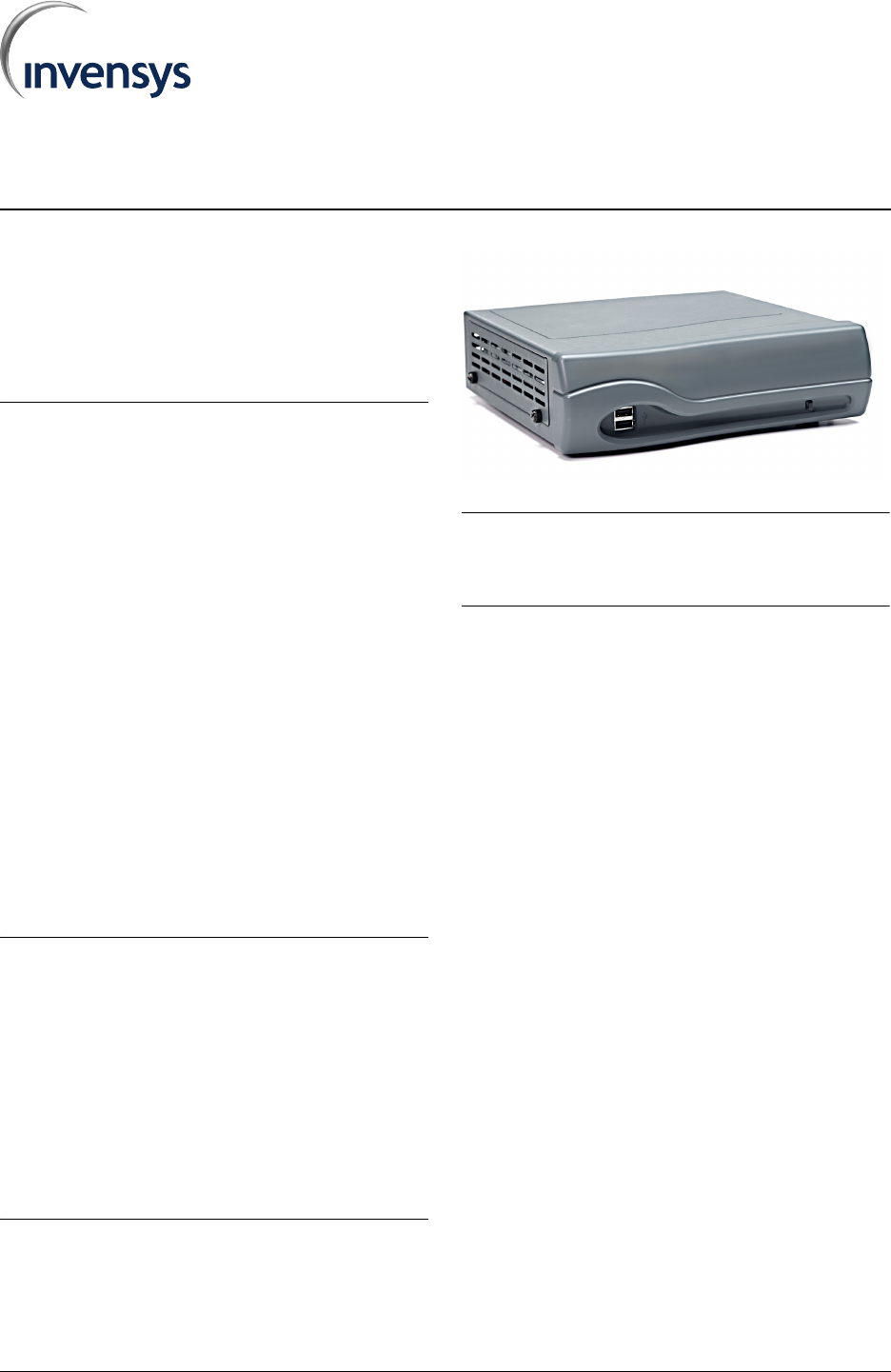
FIGURE 1. Intelliway RF Gateway
Note: To comply with FCC RF exposure requirements in
section 1.1307, a minimum separation distance of 20 cm
(8 inches) is required between the antenna and all
persons.
Inspection
Inspect the product carton for damage. If damaged,
notify carrier immediately. Inspect the Intelliway RF
Gateway for damage. Return damaged products.
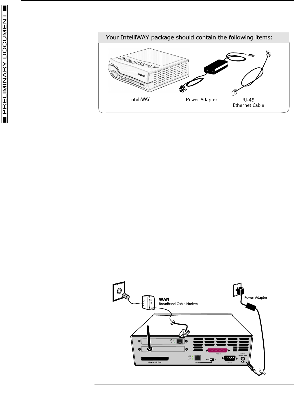
Check that the contents includes all components, as
listed below and shown in FIGURE 2. Intelliway RF
Gateway Components:
– Intelliway server
– Power adapter
– RJ-45 ethernet cable
INTELLIWAY RF GATEWAY GENERAL INSTRUCTIONS
2 PRELIMINARY DOCUMENT TD2002-EVX
FIGURE 2. Intelliway RF Gateway Components
Installation
Location
The Intelliway RF Gateway is an Energy Star compliant low power consumption,
“always-on” server appliance. Proper location and setup of the device is
essential for achieving top performance and longevity. The Intelliway RF
Gateway should be situated in a clean, flat, stable, open environment with
adequate ventilation and isolated from any forms of moisture, dust and
contaminates. Placement of the device on or near a desktop or industrial
shelving is recommended, however, placement within a wiring closet or wall
mounting (professional installation recommended) are also viable alternatives.
Connections
The following sections provide instructions for connecting to the Internet and the
procedural steps for applying power to the gateway.
Internet connection
FIGURE 3. Intelliway RF Gateway connections
Note: Be careful to avoid reversing the WAN and LAN connections. The Intelliway RF
Gateway connector is located on the upper part of the back panel.

GENERAL INSTRUCTIONS CONNECTING POWER
8/5/02 PRELIMINARY DOCUMENT 3
1. Refer to FIGURE 3. Intelliway RF Gateway connections, and connect your external
Cable to the Intelliway RF Gateway with an Ethernet cable (supplied by your modem
manufacturer).
2. Turn on your external Cable modem.
Connecting Power
Note: There is NO power switch located on the Intelliway RF Gateway unit. The unit is
“on” when you plug it in to a power outlet. Turning the gateway “off” is controlled via the
gateway software or by unplugging the power adapter.
1. Plug the supplied power adaptor into the DC connector on the back of the Intelliway
RF Gateway and insert the power plug into a wall socket with surge protection.
2. The Intelliway RF Gateway will automatically run a 2-3 minute sequential self-test.
The LED light located on the front of the gateway will indicate the status of the
process, starting from a green blinking light through a solid green light if every test
passes.
Note: You may see a very subtle orange blinking over the Solid Green light when the
data is processing
3. Follow the LED readouts and proceed accordingly. Refer to TABLE 1. LED indicator
descriptions for a listing of light indications.
TABLE 1. LED indicator descriptions
Operation
The Intelliway RF Gateway is pre-configured to automatically use the WAN interface for
connecting to the GoodWatts.com server. After a connection is made, the home-specific
information is downloaded into the gateway and the RF device network is started, as
shown in FIGURE 4. GoodWatts RF device network.
FIGURE 4. GoodWatts RF device network
LED Status Indication Action
Green Blinking (1 blink) Process basic hardware testing Wait for LED status change
Green Blinking (2 blinks) Process extensive hardware testing Wait for LED status change
Green Blinking (3 blinks) Process software testing Wait for LED status change
Green Blinking (4 blinks) Indicates Internet (WAN) connection
needs configuration via Intelliway RF
Gateway software
Contact Technical Support
Solid Green light Indicates Internet (WAN) connectivity
is complete
No action necessary
Red Blinking An internal failure has occurred Contact technical support
Gateway
Thermostat
M
e
t
e
r
L
o
a
d
Contr
o
l
M
e
t
er

TD2002-EVX INTELLIWAY RF GATEWAY PRINTED IN U.S.A.
© Invensys 2002
All specifications are nominal and may change as design improvements are introduced. Invensys shall not be liable for damages resulting from mis-
application or misuse of its products.
Marks bearing ® and/or ™ are registered trademarks and trademarks of Invensys.
Terms and product names in this document may be trademarks of others.