Robertshaw Controls 2400MHZ230FS CargoLink Fuel Sensor (wireless) User Manual Exhibit D Users Manual per 2 1033 b3
Robertshaw Controls Company CargoLink Fuel Sensor (wireless) Exhibit D Users Manual per 2 1033 b3
Exhibit D Users Manual per 2 1033 b3
Kit Bulletin
KT40-1253-4
Date: September 16, 2014
Subject: CargoLink™ Fuel Sensor (wireless)
Used on: Truck and Trailer Units
Bulletin Location: TSA Info Central\Kit Bulletins
ESA Info Central\Kit Bulletins
Installation Instructions: See Truck and Trailer Edition CargoLink™ TK 55151-11-IM
Description: This kit contains a new CargoLink™ wireless fuel level sensor, tank gauge float assembly, activation
magnet & associated hardware. It requires installation of the CargoLink™ Coordinator available
separately. The included tank gauge float assembly must be installed with any new wireless fuel
sensor application. It can be used on a wide variety of Thermo King and other brands of tanks. The
sensor is set from the factory for 22” diameter fuel tanks. The sensor is wirelessly configurable to
other tank sizes using the available CargoLink™ service tool application, available separately.
Applications: Transport Refrigeration unit controls & monitoring for fuel level.
lMicroprocessor control with digital fuel sensor requirements for a 1-4V signal (also configurable
to 0-5V).
lAnalog Fuel Level alarm switch requirement for 12V system voltage at alarm activation (Fuel
Level ≤ 15%).
lOther telematics & unit control systems.
Benefits:
Warning: Use caution when working in or around the area of the diesel fuel tank. Diesel fuel vapors are
potentially explosive. Do not smoke while working near the diesel fuel tank. Do not breath escaping
fuel system fumes or vapors.
Caution: Changes or Modifications not expressly approved by Thermo King could void the user's authority to
operate the equipment
Note: Always wear protective clothing, gloves and eye wear when working in or around diesel fuel. All
personal protective equipment must be used in the manner specified by the manufacturer. Protection
afforded by the equipment may be impaired if the equipment is used in a manner not specified by the
manufacturer.
IMPORTANT INSTALLATION NOTES:
• The fuel level sensor must be paired to a properly
installed CargoLink™ WPAN Coordinator prior to
installation. See “Installation - Pairing Sensors”.
• The Fuel Level Sensor – “FLS” (digital) or Fuel Level
Alarm – “FLA” (analog alarm) wired output of the
Coordinator should be wired into the corresponding
controller device prior to pairing. See the wiring
diagram figure 1 & 2.
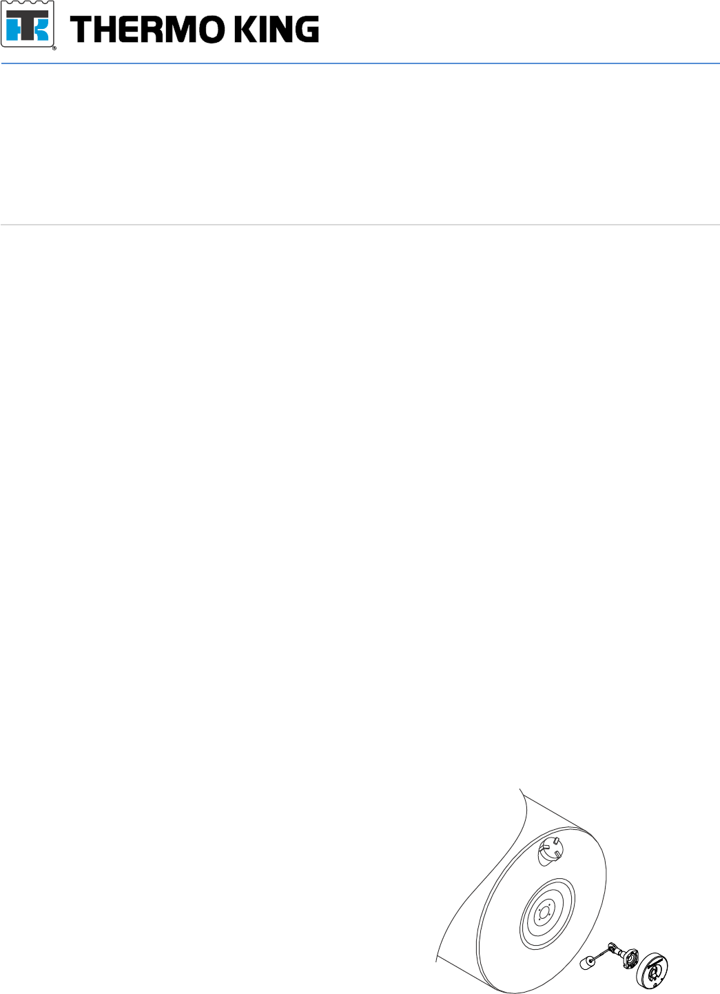
• The supplied fuel float assembly must be installed in
the tank prior to installation of the fuel level sensor.
• The existing tank fuel floats do not have a magnet
drive strong enough to move the gauge used in
the fuel level sensor and must be replaced.
• The fuel level sensor attaches to the float arm
assembly with an interference fit that will require light
use of a rubber mallet to seat the sensor square on
the float arm assembly. This is used to assure a
strong mechanical resistance to the effects of road
vibration. The gauge is secured to the float arm using
two 6/32 x ½” Tri-lobe thread forming
screws(included).
lCargoLink™ Wireless Technology : No exposed wires to break.
lFast retrofit or new install on most tanks, no extra ports required.
lAnti-slosh technology provides reliable level measurement at all tank volumes.
lDurable, long-lasting construction.
lWeather/waterproof to IP69K including diesel fuel and chemical wash down.
40-1253 Kit - Fuel Sensor (wireless)
Part no. Description Qty
42-1473 Fuel Level Sensor - (wireless) 1
42-1192 Magnet disc CargoLink 1
NSS Fuel tank gauge float 2
51-2837 Screw (6-32 x .5 in long) 2
NSS Screw (1/4-28 x .885 in long) 4
41-2457 Socket terminal 1
Webiste is www.thermoking.com
Fuel Level Alarm
4. Fuel Level Alarm wiring – applicable only to
controllers with fuel level alarm input.
a. For systems that have a system level voltage (12-
14V) fuel alarm input without a variable fuel level
input, connect the Coordinator output wire labeled
FLA to the alarm circuit.
Pairing
Pairing is the process of identifying the fuel
sensor to the CargoLink network.
Important: Keep all sensors away from the
magnets for at least 60 seconds before beginning
the pairing process.
1. Bring all sensors to be paired directly to the
coordinator module. The pairing activity should
occur within 10 feet of the coordinator module
especially when multiple systems are being
installed concurrently.
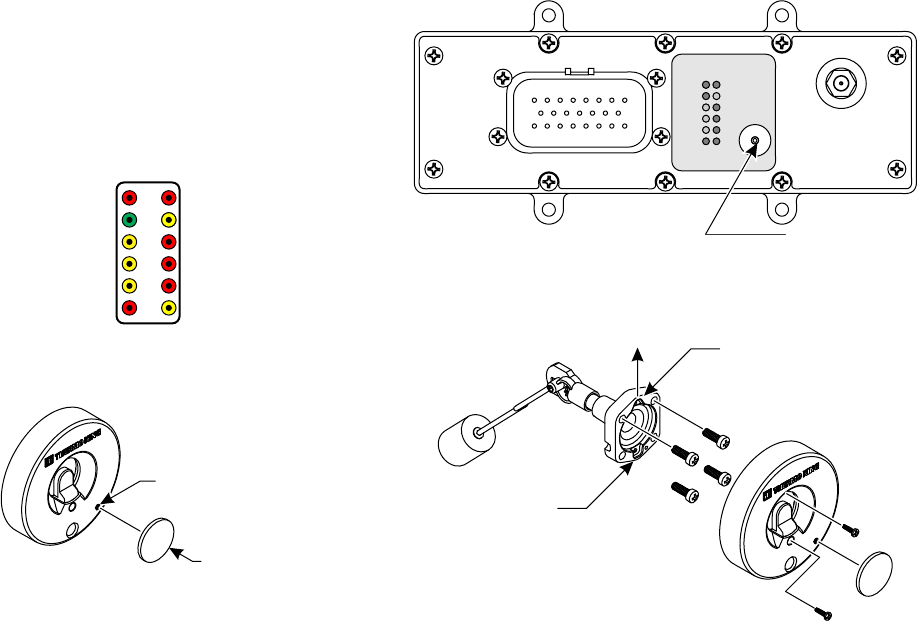
2. Verify the red PWR (Power) LED is illuminated on
the Coordinator. See figure 3.
3. Press and release the switch on the Coordinator
until the FUEL LED is illuminated.
Note: Repeated presses of the switch will cycle through
all selections before starting over at the top.
4. Once FUEL is selected, press and hold the
switch again until the green PAR (Pairing) LED
illuminates.
a. One green and two red LED’s will now be
illuminated on the module indicating it is in the
pairing mode.
NOTE: If no action is taken within 30 seconds, the green
PAR LED on the module will begin flashing
rapidly for 8 seconds and then go out. Repeat
step 4 to restart the pairing procedures.
5. With the three LED's (PWR, FUEL & PAR)
illuminated on the coordinator, bring the supplied
magnet and sensor together quickly two times
and then remove the magnet.
Note: The correct orientation of the fuel sensor to the
magnet must be followed or the pairing process
will not work. See figure 5 for proper pairing
target alignment.
INSTALLATION PROCEDURE:
SR-2 & SR-3
1. Wiring the Coordinator to SR-2 & SR-3 Fuel
sensor input – if wiring to an SR-4, go to step 2, if
wiring to a control that only accepts a fuel level
alarm input, go to step 7.
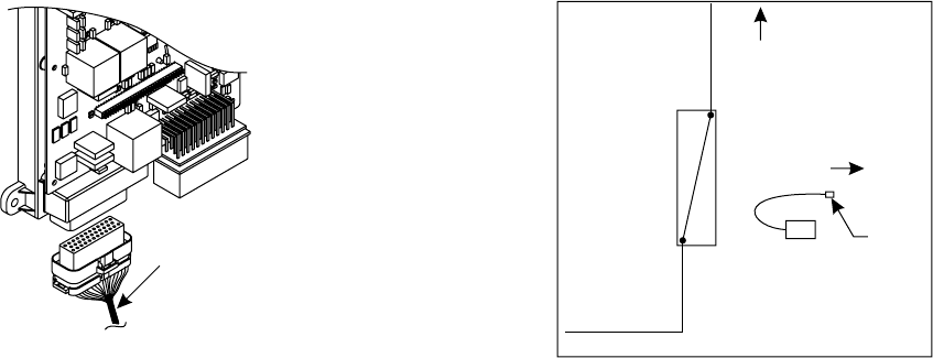
a. Locate the “FLL” wire at connector J3 pin 23 on
the SR-2 or SR-3 controller.
b. Cut FLL, leaving 102 mm (4”) of wire from the
connector. Use a single sided crimp connector
and cap the cut wire no longer connected to the
controller. Go to Step 3.
c. If no wire is connected to pin 23, use included
terminal (41-2457) and crimp on FLS wire. Insert
into J3 pin 23. Go to Step 3b.
SR-4
2. Wiring the Coordinator to SR-4 fuel sensor input
a. Locate the “FUEL-01” wire at the 3 wire option
harness located at the bottom of the control
cabinet or at connector J1 pin 2.
b. Cut FUEL 01, leaving 102 mm (4”) of wire from
the connector. Use a single sided crimp connector
and cap the cut wire no longer connected to the
controller. Go to Step 3.
c. If no wire is connected to pin 2, use included
terminal and crimp on FLS wire. Insert into
J1 pin 2. Go to Step 3b.
ALL SR Controls
3. Wiring the Coordinator to the controller & Menu
Setup.
a. The fuel level sensor output wire from the
Coordinator is labeled as FLS. Connect the FLS
wire to the FLL or FUEL-01 connections identified
above using a crimp connector supplied with the
Coordinator kit.
b. Enter the guarded access menu on the controller
and change the Fuel Level sensor input type to
“solid state”. Proceed to the pairing operation.
Note: The Fuel Level Sensor input type must be set
to “Solid State”. Setting it to “Float” will result
in inaccurate fuel level readings.
End SR Controller wiring
SR-2 & SR-3 Controller wiring
Locate the FLL
wire and cut 4”
from connector
Figure 1 Figure 2
FUEL-01
Coordinator
FLS
Unit
Harness
Controller
SR-4 Controller Wiring
Cap
cut
wire
a. The LED on the fuel sensor will quickly flash
yellow four times, then a short pause, followed by
a continuous flashing green. This indicates the
fuel sensor is now ready for the pairing process to
begin.
6. While the green LED on the fuel sensor is flashing
continuously, bring the magnet and fuel sensor
together and apart three times in a row within 10
seconds.
a. When the magnet is recognized by the sensor, the
green LED on the sensor will turn off.
b. After a few seconds, the PAR and FUEL switch
LED's will flash slowly indicating the sensor has
been correctly paired.
c. If unsuccessful, the PAR green LED will flash
rapidly and you will need to repeat the sequence
starting at step #3.
Important: Only one fuel sensor may be paired with
a Coordinator. Pairing a 2nd fuel sensor to a
Coordinator will result in the first fuel sensor being
removed from connection with the Coordinator.
Float Installation
1. Drain fuel tank to below 1/2 full reading on site
gauge. Remove existing float and gasket.
2. Install new gasket on float assembly.
3. Insert the “bent arm” float assembly with the
correct orientation see figure 6. Secure float
assembly with the 4 bolts (1/4-28) to the tank and
torque to 20-50 in lbs.
Note: Do not over torque bolts because this could
damage gasket and the gauge.
4. Installing fuel sensor on tank.
a. Empty tank to below ½ full and clean the surface
of the tank where the gauge will be installed.
b. Orientate fuel sensor with “1/2”gauge at the 12:00
position.
c. Place fuel sensor over float arm assembly.
d. Fully seat sensor onto the assembly by gently
tapping around the sensor face with a plastic or
rubber hammer.
Note: Sensor must be fully seated on the gauge prior to
securing the sensor with supplied screws. Do not
use screws to pull sensor onto the float arm
assembly.
e. Use the supplied screws to secure sensor onto
the float arm assembly. Torque screws to
between 12-15 in-lbs.
f. Fill tank with diesel fuel and confirm there are no
fuel leaks and repair if necessary.
Note: If fuel tank is less than 10% full at time of
installation, it may not respond to the float level.
Use magnet to move the gauge needle towards
the “1/4” full mark until it responds to the float
level position.
5. Confirm fuel level reading on controller HMI
display under gauge menu.
Note: This device complies with Industry Canada
licence-exempt RSS standard(s). Operation is
subject to the following two conditions: (1) This
device may not cause interference, and (2) This
device must accept any interference, including
interference that may cause undesired operation
of the device.
Note: Le présent appareil est conforme aux CNR
d'Industrie Canada applicables aux appareils
radio exempts de licence. L'exploitation est
autorisée aux deux conditions suivantes : (1)
l'appareil ne doit pas produire de brouillage, et (2)
l'utilisateur de l'appareil doit accepter tout
brouillage radioélectrique subi, même si le
brouillage est susceptible d'en compromettre le
fonctionnement"
Coordinator Selections
(Power / Diagnostic) PWR • • FUEL
(Pairing) PAR • • TEMP (Temperature)
(Zone1) Z1 • • GUI (Graphical User Interface)
(Zone2) Z2 • • 01 (Option 1)
(Zone3) Z3 • • UN (Unpair)
(Door) DR • • DI (Diagnostic)
Figure 3
Figure 6
Square
Round
Up
Figure 5
Magnet
Pairing Target
PWR
COM
Z1
Z2
Z3
DR
FUEL
TEMP
GUI
O1
UN
DI
Coordinator Module
Coordinator
Module Switch
Figure 4