Robotron G5P PCI VHF/UHF Receiver User Manual Appendix G
Robotron Pty Ltd PCI VHF/UHF Receiver Appendix G
Robotron >
Manual

FCC ID: HNL-G5P Report No. M060139_Cert_G3_Internal_Receiver
EMC Technologies Pty Ltd – 57 Assembly Drive, Tullamarine VIC 3043 Australia
www.emctech.com.au
EMC Technologies Report Number: M060139_Cert_G3_Internal_Receiver
APPENDIX G
User Manual
WiNRADiO®
G3xx VHF/UHF Receiver
User’s Guide

WiNRADiO G3XX VHF/UHF Receiver
2
Published by
WiNRADiO Communications
PO Box 6118, St Kilda Road, Melbourne 3004, Australia
© 2006 WiNRADiO Communications, Melbourne
All rights reserved. No part of this book may be reproduced or transmitted in any form or by any
means without the written permission of the publisher.
Trademarks
WiNRADiO, G3 and Radio Basic are trademarks of WiNRADiO Communications
All other brand and product names are trademarks of their respective owners.
Patents
WiNRADiO technology is protected by US Pat. No. 6,289,207 and other pending US and
international patent applications.
Printed in Australia

WiNRADiO G3XX User’s Manual
3
FCC Notice
This equiment has been tested and found to comply with the limits for a Class B digital device,
pursuant to Part 15 of the FCC Rules. These limits are designed to provide reasonable protection
against harmful interference in a residential installation. This equipment generates, uses and can
radiate radio frequency energy and, if not installed and used in accordance with the instructions,
may cause harmful interference to radio communications. However, there is no guarantee that
interference will not occur in a particular installation. If this equipment does cause harmful
interference to radio or television reception, which can be determined by turning the equipment off
and on, the user is encouraged to try to correct the interference by one or more of the following
measures:
• Reorient or relocate the receiving antenna
• Increase the separation between the equipment and the receiver
• Connect the computer into an outlet on a circuit different from that to which the receiver is
connected
• Consult an authorised dealer or an experienced radio/TV technician for help
Caution
To comply with the limits for the Class B digital device, pursuant to Part 15 of the FCC rules, the
WiNRADiO card must be installed in computer equipment certified to comply with the Class B
limits. Only peripherals certified to comply with the Class B limits may be attached to the
computer containing the WiNRADiO receiver. Only original cables and power adapters must be
used. Operation with non-certified cables, power adapters and peripherals may result in
interference to radio and TV reception.
Modifications
Any changes or modifications to the WiNRADiO receiver could void the user's authority to operate
this equipment, as well as void the manufacturer’s warranty.
Limitation of Liability and Remedies
The information published in this book has been compiled from several sources. While every
effort has been made to ensure its accuracy, neither the authors nor the publisher can guarantee
that all information is entirely correct or up-to-date. Furthermore, neither the authors nor the
publisher can take any responsibility for the use of this information or any consequences arising
therefrom. WiNRADiO Communications shall have no liability for any damages due to lost profits,
loss of use or anticipated benefits, or other incidental, special or punitive damages arising from the
use of, or the inability to use, the WiNRADiO receiver, whether arising out of contract, negligence,
tort or under any warranty, even if WiNRADiO Communications has been advised of the possibility
of such damages. In no event shall WiNRADiO Communications ' liability for damages exceed the
amount paid for this product. WiNRADiO Communications neither assumes nor authorises anyone
to assume for it any other liabilities.
Warning
In certain countries or states it may be illegal to monitor certain frequencies. We cannot accept
any responsibility for the consequences of your non-compliance with government regulations. If
you are in doubt about the regulations in your country or state, please contact your nearest radio
communications regulatory authority.

WiNRADiO G3XX VHF/UHF Receiver
4
Table of Contents
Table of Contents .................................................................................... 4
Introduction.............................................................................................. 6
G3XX Receiver Models............................................................................ 7
Installation................................................................................................ 9
System Requirements.......................................................................... 9
Hardware Installation ......................................................................... 10
Software Installation........................................................................... 11
Setting up the Sound Card................................................................. 12
Connecting the Antenna .................................................................... 13
Getting Started....................................................................................... 14
Tuning WiNRADiO G3XX....................................................................... 16
Manual Frequency Entry.................................................................... 16
Tuning Knob ...................................................................................... 18
Keyboard Tuning................................................................................ 18
Incremental Tuning Pad..................................................................... 19
Tune To Peak .................................................................................... 19
AFC (Automatic Frequency Control).................................................. 20
Frequency Stepping........................................................................... 20
The Demodulator................................................................................... 22
Selecting Demodulation Mode ........................................................... 22
Real-time Spectrum Scope ................................................................ 23
Setting and Adjusting IF Bandwidth ................................................... 25
IF Shift and Passband Tuning............................................................ 27
Volume Control .................................................................................. 28
Mute Control ...................................................................................... 28
Software AGC.................................................................................... 29
AF Squelch (Audio Filter Squelch)..................................................... 30
Notch Filter ........................................................................................ 31
Audio Filter......................................................................................... 33
Noise Blanker..................................................................................... 34
Receiver Incremental Tuning (RIT).................................................... 34
Recording and Playback .................................................................... 35
Test and Measurement ...................................................................... 38
Demodulator Structure ......................................................................... 40
Other Demodulator Settings .............................................................. 41
Receiver Gain Control........................................................................... 42
AGC................................................................................................... 42
IF Gain Control................................................................................... 43
RF Gain Control................................................................................. 43

WiNRADiO G3XX User’s Manual
5
Squelch Control .....................................................................................44
Memory...................................................................................................46
Storing a Frequency into Memory ......................................................46
Recalling a Frequency from Memory..................................................48
Editing Memory ..................................................................................49
Deleting a Frequency .........................................................................49
Saving a Memory File.........................................................................50
Opening a Memory File ......................................................................50
Memory Stepping ...............................................................................50
Scanning.................................................................................................51
Immediate Scanning (Searching) .......................................................51
Scanner Configuration........................................................................52
Groups ...............................................................................................53
Exclusions ..........................................................................................53
Frequency Range Scanning...............................................................54
Memory Scanning ..............................................................................56
S-meter ...................................................................................................57
Power Switch..........................................................................................59
Date and Time Displays.........................................................................59
Spectrum Analyzer ................................................................................60
Appendix A – Troubleshooting.............................................................66
Appendix B – Sound Card Controls.....................................................71
Appendix C – Dealing with Interference ..............................................73
Appendix D – Inside WR-G3XX Hardware............................................75
Appendix E – Inside WR-G3XX Demodulator ......................................77
Appendix F – Developer Support .........................................................80
Appendix G – Hardware Options..........................................................81
Appendix H – Frequency Calibration ...................................................82
Appendix I – S-meter Calibration..........................................................84
Appendix J – USB Interface Diagnostics.............................................85
Declaration of Conformity........................... Error! Bookmark not defined.

WiNRADiO G3XX VHF/UHF Receiver
6
Introduction
Welcome to the WiNRADiO G3XX receiver. This advanced receiver is the
result of a quest to combine many years of accumulated know-how in
computer-based radio receivers with the latest advances in components and
digital signal processing techniques.
In designing this receiver, we strived to provide the optimum balance of
sensitivity, selectivity and dynamic range, yet maintaining low cost and
implementing a number of significant features previously available only on
receivers significantly more expensive, bulky and far less friendly to the user.
While we attempted to implement many more features and functions than
normally would be found on a typical communications receiver, we also strived
to keep the control panel streamlined, logical and easy to use.
The WiNRADiO G3XX receivers transform any modern PC desktop into a
sophisticated VHF/UHF monitoring station offering surprising power and
flexibility, and enjoyment of use.
We hope you will like the spectrum analyzer with a 16 Hz resolution
bandwidth, continuous IF bandwidth adjustment in 1 Hz steps, graphical pass-
band tuning, graphical notch filter, ultra-sensitive, selective and accurate S-
meter, the convenient tuning and scanning facilities, the test and measurement
functions, and many other innovative features.
The WiNRADiO G3XX is not designed to be an ordinary radio receiver. It is
intended to be an exemplary radio communications instrument, crafted with
meticulous care and dedication to excellence.
We wish you much success and many hours of enjoyment in putting it to your
good use.
Please don’t forget to register as a WiNRADiO user to receive news about new
products, accessories and software upgrades for your G3XX receiver. Use our on-line
registration form at www.winradio.com/register to take advantage of this free service.
WiNRADiO G3XX User’s Manual
G3XX Receiver Models
There are two basic models of the WiNRADiO G3XX receiver:
• G3XXi (PCI card based “internal” model)
• G3XXe (USB based “external” model)
Both receivers have similar parameters and similar software user interface.
This manual covers the installation and operational aspects for both types.
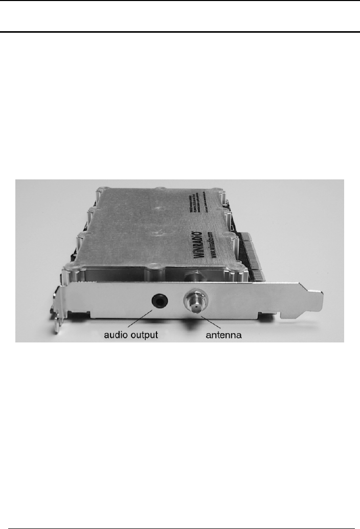
The G3XXi model has two connectors: the antenna connector (SMA type,
50 ohm) and an audio output:
The audio output is compatible with a PC sound card Line input, or can be
simply connected directly to an amplified multimedia speaker, or any other
suitable audio equipment. Standard 3.5mm stereo audio jack is used.
The advantage of this model is that it does not require any external power
supply, and does not occupy any additional desk space. The receiver is very
well shielded to prevent any interference generated by the PC from entering
the receiver. The receiver comes with a suitable “audio lead” to connect the
audio output to a sound card input.
7
WiNRADiO G3XX VHF/UHF Receiver
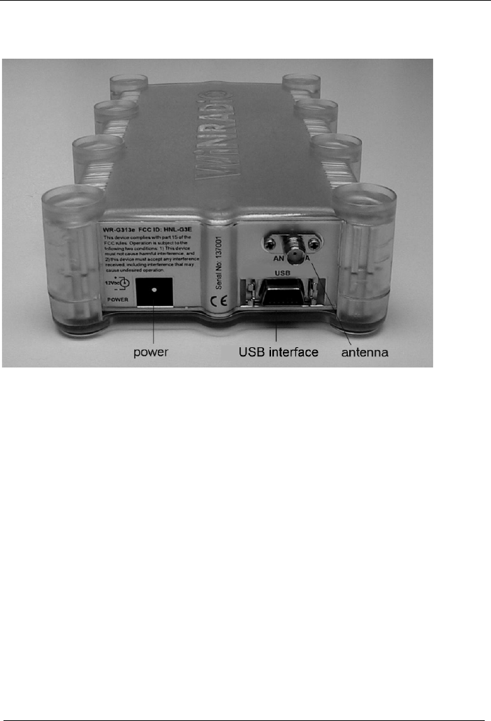
The external G3XXe model has three connectors:
The power jack accepts 12 V DC (the power adapter must be rated for
minimum 500 mA). To minimize interference, a linear-mode power adapter is
recommended (as supplied by WiNRADiO).
The antenna input is an SMA-type connector with 50 ohm impedance.
The USB interface is compatible with both USB 1.0 and 2.0 standards and
serves to connect the receiver to a desktop or a laptop computer.
8

WiNRADiO G3XX User’s Manual
9
Installation
The WiNRADiO G3XX package contains the following items:
• WiNRADiO G3XXi or G3XXe receiver
• USB interface cable (G3XXe receiver only)
• WiNRADiO software on a CD ROM
• Start-up indoor antenna
• Audio cable (G3XXi receiver only)
• This User’s Guide
• Warranty information
In order for the WiNRADiO receiver to function, your IBM PC compatible
computer must meet the minimum system requirements specified below.
System Requirements
Minimum Recommended
CPU 500 MHz,
Pentium III 1GHz or higher,
Pentium IV or Athlon
RAM 64 MB 256 MB or more
Display SVGA SVGA (16 mil. colors)
HD free space 20 MB 40 MB
Sound card* SoundBlaster
compatible 16 bit Creative Sound Blaster,
16 or 32 bit
OS Windows
98/ME/2000/XP Windows 2000/XP
* Sound card is only required with the G3XXe model (for playback only)
Do you have any suggestions about how we could further improve our product, or do
you wish to tell us of your experiences using this receiver in your application? Please
do not hesitate to leave your comments on www.winradio.com/feedback. We always
love hearing from you.

WiNRADiO G3XX VHF/UHF Receiver
10
Hardware Installation
G3XXi model (PCI card)
1. Turn the computer off and disconnect the power cord.
2. Remove the computer case. Choose an empty PCI slot, as far as possible
from the power supply and from other cards.
3. First touch the computer metalwork with your hand to drain any static
charge, then carefully insert the card into the vacant slot and push down
until it is firmly seated. Screw the metal bracket at the end of the card to
the computer case. (This must be done to provide proper grounding for the
card).
4. Replace the computer case and reconnect the power cord.
5. Connect the supplied audio lead between the receiver output (a standard
audio jack) and the sound card Line Input. (If there is no Line input on your
PC, as is the case with some laptops, you may use alternative inputs, such
as the Microphone input.) Or, if you prefer, you can connect the receiver
directly to an amplified speaker or other suitable audio equipment.
G3XXe model (external model)
1. Connect the receiver to the USB port.
2. Connect the supplied power adapter to the power outlet on one side and
the power lead to the receiver on the other side.
3. Turn the receiver on using the power switch at front of the receiver. The
blue LED will first flash slowly, indicating that the receiver is ready. (The
flashing pattern of the blue LED has diagnostic meaning. For more
details, see Appendix J, USB Interface Diagnostics.)

WiNRADiO G3XX User’s Manual
With the G3XXe model, the demodulated audio is travelling over the USB
interface, so no connection to a sound card is necessary, except, of course,
the speaker output.
Finally, connect the supplied start-up antenna to the SMA connector at the
rear of the receiver. Extend the antenna so that it is as far away from the
computer as possible.
Software Installation
1. If the PC is off, turn it on. Windows will find the receiver and automatically
start the usual New hardware found driver installation routine. Insert the
installation CD ROM into the drive, and follow on-screen instructions.
2. After installing the drivers, choose the Run command from the Start menu
in Windows and type D:INSTALL (if the CD ROM is the D: drive on your
PC).
3. This will run the application installer, which will guide you in the installation
process.
4. After all the files have been installed to your hard disk, run the WiNRADiO
G3XX application.
Note: If the receiver is not detected by Windows, you can simply skip the driver
installation procedure, insert the CD ROM, and run the installation program,
which will also install the drivers.
WiNRADiO also manufactures a wide range of
antennas and antenna accessories suitable for many
applications. The WiNRADiO AX-71C antenna
(pictured) is especially suitable for the G3XX
receivers. Visit our web site www.winradio.com for
more information about WiNRADiO range of antennas
and antenna accessories.
11
WiNRADiO G3XX VHF/UHF Receiver
Setting up the Sound Card
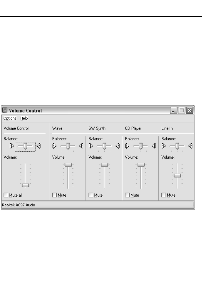
The G3XXe receiver’s audio travels via the USB interface in a digitized form,
to be played back by the sound card. The volume can be adjusted using the
Wave volume slider (which must be unmuted) or the master Volume Control.
The G3XXi receiver’s audio output is an analog Line Output. You can connect
this directly to standard amplified speakers, an external amplifier of your
choice, or your PC sound card. If you are using the sound card, the receiver
output should be physically connected to the Line Input of the sound card.
Double click on the speaker icon in the task bar, to bring up the sound card
Volume Control panel:
Make sure the Line Input is not muted, and the volume is set to approximately
half, to get started. (If the maximum volume as set on the receiver panel is not
sufficient, you may wish to increase the sound card volume later.)
If you are using the Microphone input instead of Line input, please check if
there is an Advanced button under the Microphone volume control in the
sound card control panel. If so, then click on it and uncheck the +20dB gain
check box if it exists. (The extra large gain might result in overloading the
sound card and cause distortion.)
12

WiNRADiO G3XX User’s Manual
Connecting the Antenna
Unless you already have a proper antenna in place, you might like to take
advantage of the supplied start-up antenna which comes with your G3XX
receiver.
This antenna consists of a 3-metre length of a coaxial lead-in cable, with an
additional 3 metres of insulated wire. The thinner, insulated wire at the end of
the coaxial cable is the actual antenna. It is necessary for the lead-in cable to
be as far away from the PC as possible, to reduce potential interference from
the PC.
Please note that this start-up antenna is supplied for initial tests and immediate
gratification only. It is not intended to replace a proper antenna.
The best placement of the start-up antenna depends on your actual situation,
and will often involve some experimentation. However, the basic rule is
simple: Place the antenna as close to the window as you can, and keep the
active part of the antenna as far away from the PC, and other electronic and
electrical devices, and metal objects, as possible.
An example of start-up antenna placement
No matter how good a radio receiver is, the performance of the entire receiving
system will depend on the quality of the antenna. The same applies to a
WiNRADiO receiver. To make the most of your G3XX receiver, you should
install a proper antenna. WiNRADiO may also be able to assist with our wide
range of suitable antennas – check our Web page www.winradio.com.
13
WiNRADiO G3XX VHF/UHF Receiver
Getting Started
There is often a degree of understandable impatience when exciting new
equipment such as a new WiNRADiO receiver is acquired. The following fast-
forward introduction makes it possible for you to start using your new
acquisition as quickly as possible. Detailed operation is described in the
subsequent chapters. We hope you will return to these chapters, as the
WiNRADiO G3XX receiver has many fine features which would be a shame to
miss.
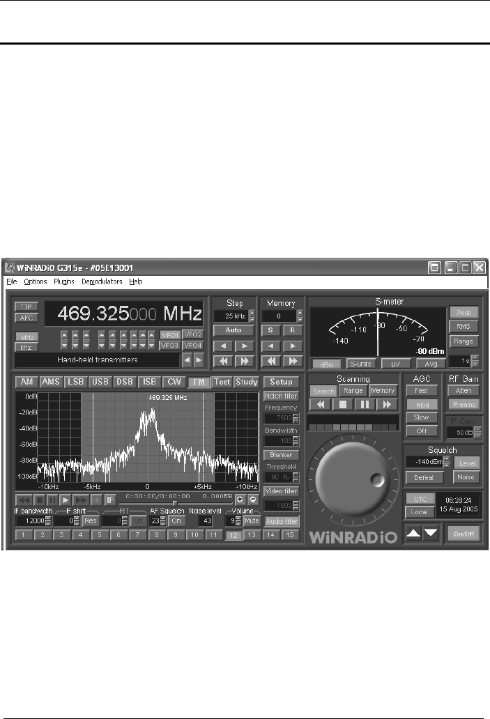
Start the WiNRADiO G3XX receiver application (by double clicking on the
WiNRADiO icon). The WiNRADiO G3XX receiver control panel will appear as
shown in the following picture:
WiNRADiO G3XX Receiver Control Panel
The WiNRADiO G3XX receiver control panel has some elements similar to
conventional receivers, and many additional features as well.
The quickest way to get started with this receiver is to check its operation on
your local AM stations.
14

WiNRADiO G3XX User’s Manual
15
Using the keyboard, type in the frequency of one your local AM stations: For
example, for 774 kHz, type in 7 7 4 , then k for kHz, then press Enter. The
typed-in frequency will appear on the digital frequency display. Then select
the AM mode by clicking on the AM button. At this point, you should be able to
see the station peak on the real-time spectrum scope, and hear the station.
Adjust the bandwidth for optimum reception using the row of numbered
buttons at the bottom of the spectrum scope panel: these represent preset IF
bandwidth. To adjust the IF bandwidth smoothly, use the IF bandwidth control
at bottom left.
You can adjust the volume using the two buttons next to the small Volume
display. (Note also the little slider between these two buttons: you can drag it
up and down to change the volume faster.) An alternative way to adjust the
volume is by using the left/right arrow keys of the PC keyboard.
Manual tuning can be done in several ways. Let’s start with the tuning knob:
Place the mouse cursor onto the upper half of the tuning knob, at which point
you will see the cursor change to a curved double ended arrow. Hold down
the right or left mouse buttons to increase or decrease the frequency, and the
knob will rotate clockwise or anti-clockwise, respectively.
If you place your cursor onto the bottom half of the tuning knob, the direction of
the rotation will reverse. (You don’t need to move the cursor up or down to
change the rotation of the knob, simply press either the left or right mouse
button.)
The rotation increment of the tuning knob is 0.5 kHz. This can be changed
easily using the Shift, Ctrl or Alt keys: If you press the Shift key while tuning,
the increment will increase ten times (to 5 kHz). Pressing Ctrl will increase the
increment a hundred times (50 kHz). On the other hand, if you use the Alt key,
the increment becomes ten times smaller: 50 Hz.
Another way of tuning is to use the up and down arrow keys on the PC
keyboard. If your mouse has a wheel, you can also use this: you might find it
somewhat similar to using the tuning knob of a conventional receiver.
If you are unable to tune to any stations at this point, please refer to Appendix
A - Troubleshooting. There are many other ways to tune the WiNRADiO
receiver other than typing the frequency or using the tuning knob. These will
be explained in detail in the following chapters.
WiNRADiO G3XX VHF/UHF Receiver
Tuning WiNRADiO G3XX
Manual Frequency Entry
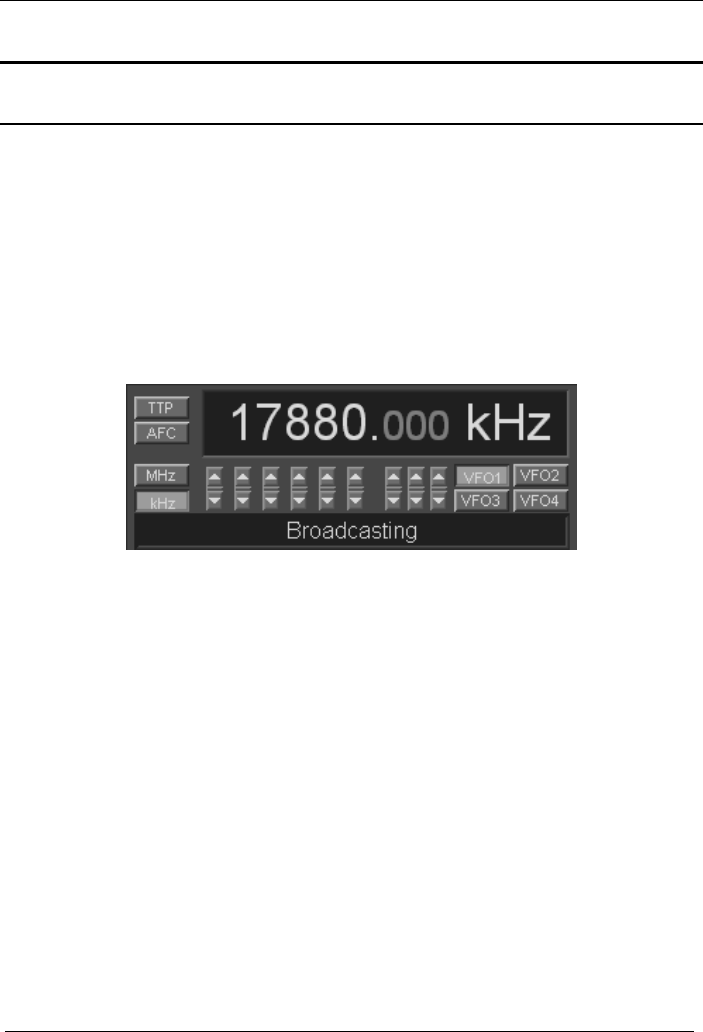
To change frequency, simply type the new frequency into the keyboard. As
soon as you press a number or decimal point, the frequency display will
activate, waiting for a frequency to be typed. You can also click on the display
to type in a new frequency in a highlighted field. After typing the new
frequency, press Enter and the receiver will instantly retune. To abort, press
Escape. To enter units, such as kHz or MHz, simply press k for kHz or m
for MHz after entering the digits. Any invalid keystrokes are ignored.
Frequencies outside the receiver limit (9 kHz to 30 MHz) will not be accepted
and the display will revert to the previous frequency.
Use the kHz or MHz buttons to select how you wish the frequency to be
displayed.
The up/down buttons under the individual digits make it possible to quickly
step up or down the frequency in the corresponding positions. (The little slider
buttons between the up/down buttons can be used for faster adjustment.)
The VFO buttons make it possible to select from four different VFOs. A VFO is
a kind of frequency memory making it possible to quickly switch between
several frequencies. For example, if you tune to Frequency 1 using VFO1, and
Frequency 2 using VFO2, then you can alter between Frequency 1 and
Frequency 2 by simply clicking on the corresponding VFOs.
16
WiNRADiO G3XX User’s Manual
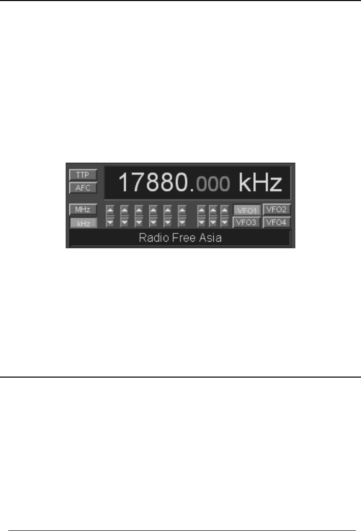
Under these buttons there is a Band description window. This window
shows the band allocation of the currently tuned frequency. While the
displayed band descriptions are specific to the North American standard, they
are based on international treaties and therefore are generally applicable
worldwide with minor differences, which can be easily edited by the user.
The band descriptions can be overridden with a call sign or a user-defined
description of a particular frequency stored in memory. This overrides the band
description for a particular frequency only.
It is also possible to change the naming and frequency allocations for entire
frequency bands. This can be done by editing the file called bands.csv in the
WiNRADiO installation folder. (This is a standard “comma-separated-value”
format file which can be edited using a spreadsheet application, such as
Microsoft Excel.)
Did you know?
VFO stands for Variable Frequency Oscillator. This is a historical term dating
back to the era of analog tuned radios. Before digitally tuned receivers were
invented, there was no easy way to store and recall frequencies. Professional
receivers had switchable oscillators where the oscillators (and their variable
capacitors) themselves served as analog frequency memories. The name and
the net effect remain, but the principle has changed: There is no need for
multiple oscillators in modern receivers to implement this function. The
frequency is simply stored in a digital memory.
17

WiNRADiO G3XX VHF/UHF Receiver
Tuning Knob
The Tuning Knob makes it possible to adjust the frequency in fixed 50 Hz,
500 Hz, 5 kHz or 50 kHz steps.
To use the tuning knob, position the mouse cursor over the knob (the cursor
will turn into a curved double ended arrow) and click on either the left or right
mouse button. If the cursor is on the top half of the knob, the left button will
decrease the frequency, and the right button will increase the frequency. If the
cursor is in the lower half, the opposite will occur (and the cursor will invert its
shape).
You don’t need to move up or down with the cursor to change the rotation of
the knob. Simply press either the right or left mouse button.
As the knob rotates, the frequency will change in 500 Hz steps. Holding the
mouse button down will accelerate the tuning.
The step size can be changed to 50 Hz, 5 kHz or 50 kHz, using the Alt, Shift
or Ctrl keys, respectively, while clicking the tuning knob with mouse button.
Note that the Fine Tune Knob can also be conveniently rotated using a wheel
of a wheel-equipped mouse, or any other standard Windows-supported
pointing device.
Keyboard Tuning
The receiver frequency can also be adjusted using the keyboard cursor control
keys (the “arrow” keys): Using the up/down arrow keys, the frequency
changes in 10 Hz steps. Pressing the Shift key simultaneously results in 100
Hz steps, while the Ctrl key changes the step size to 1 kHz.
18
WiNRADiO G3XX User’s Manual
Incremental Tuning Pad
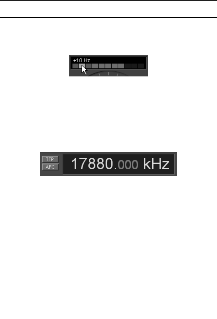
This unique tuning tool is located above the Tuning Knob. If the mouse is
positioned above one of the coloured squares, the square lights up and the
associated tuning increment value appears:
Clicking on the square with the left mouse button results in increasing the
frequency, clicking with the right mouse button will decrease the frequency.
There are several convenient tuning increments to choose from: 1 Hz, 10 Hz,
100 Hz, 1 kHz, 5 kHz, 6.25 kHz, 8.33 kHz, 9 kHz, 10 kHz, 12.5 kHz and 25
kHz.
Tune To Peak
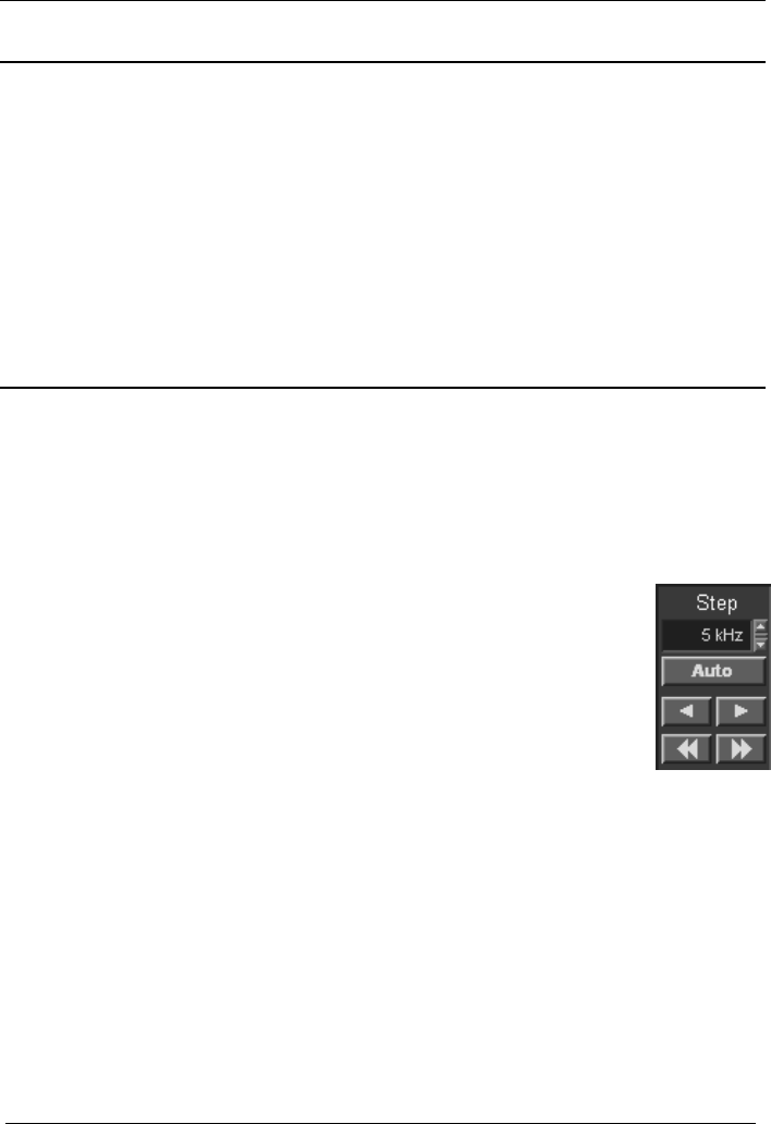
The Tune to Peak function can be invoked by pressing the TTP button. The
receiver will tune to the signal peak (provided the peak falls inside the selected
IF bandwidth – the highlighted area of the real-time frequency spectrum).
Depending on the location of the peak and type of signal, it may take several
seconds for the receiver to tune in accurately, by a successive approximation
process.
In the FM mode, the Tune to Peak function will work correctly, i.e. tune to the
centre of the signal, even though the sidebands may be higher than the carrier
frequency.
In LSB and USB modes, the success of this facility will depend on the type of
modulation signal. It may be useful for certain types of data modulation (fax),
but is not usually recommended for voice modulation.
19
WiNRADiO G3XX VHF/UHF Receiver
AFC (Automatic Frequency Control)
The Automatic Frequency Control function is activated by pressing the AFC
button. It will keep the receiver tuned to the selected station if the transmitter
frequency drifts.
While this function is active, the receiver will periodically check the received
signal and correct the frequency in approximately five-second intervals.
This facility is not recommended for LSB and USB modes with voice
modulation.
Frequency Stepping
The Frequency Stepping facility makes it possible to specify an arbitrary
frequency step size. To change the step size, click on the associated display
and enter the required value (from 1 Hz to 1 MHz). You can also use the up
and down buttons on the right of the display, to select from commonly used
step sizes. For convenience, you can also use the small slider between the
two buttons.
When the step size is selected, you can step up or down from the
currently displayed frequency using the left or right arrow buttons
under the step size display. The double-arrow buttons further
down will cause stepping by a step size ten times larger.
Stepping can also be done using the keyboard Pg Up or Pg
Down keys.
For example, if you wish to browse the AM broadcast band
(approx. 530 to 1620 kHz), set the step size to 10 kHz (for North and South
America) or 9 kHz (for the rest of the world), which is the channel separation
for AM broadcast stations.
Tune manually to any station first, then step up or down to browse the band.
To browse the shortwave broadcast stations (2.3 to 30 MHz), 5 kHz works
well.
20
WiNRADiO G3XX User’s Manual
This type of fixed-size stepping is convenient if you wish to explore a
frequency band where the channels are equally separated. However, you
should ensure that the stepping frequencies fall on the actual channel
frequencies in the band. If you know the channel separation but are unsure
about the exact frequency of the first channel, tune to an active channel using
manual tuning first, and only then step up or down in fixed steps.
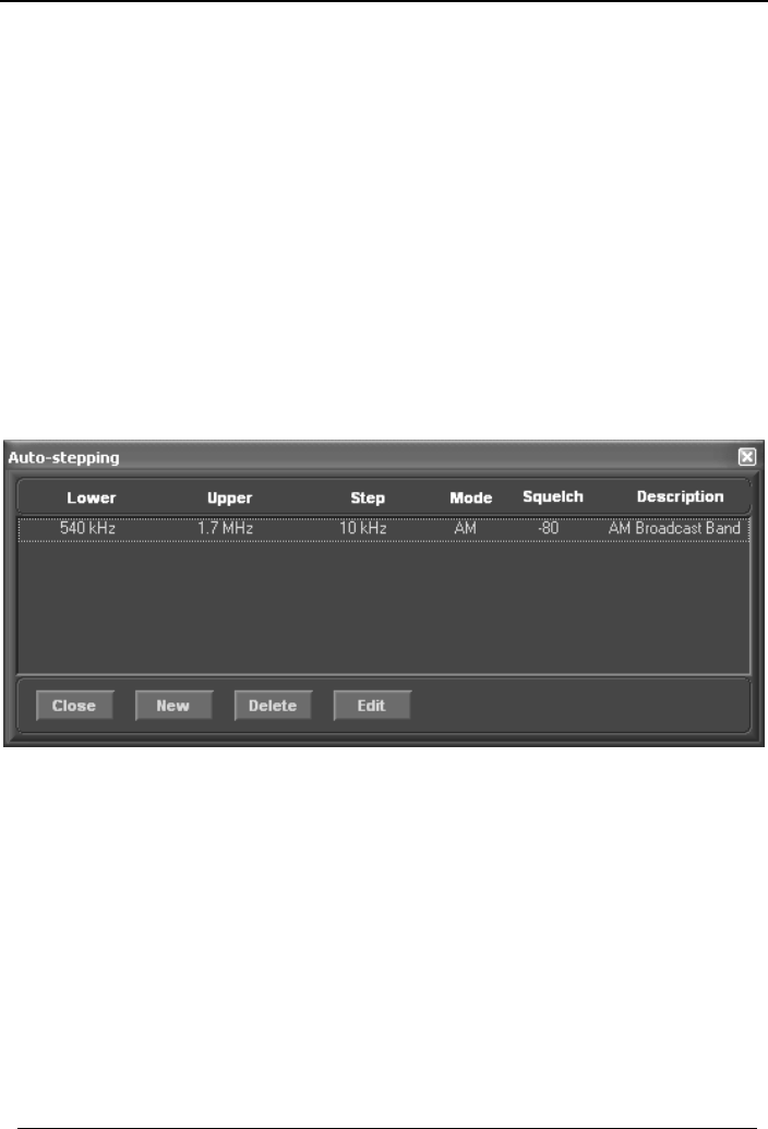
The Auto button engages Auto-stepping, which provides a significant
enhancement over fixed stepping. When properly configured, auto-stepping
will automatically set the step size according to the frequency you are tuned to.
Auto-stepping can be also used to associate particular mode and squelch
settings with specified frequency ranges.
To configure the auto-stepping ranges, go to Options | Autostepping in the
top bar menu. The following window opens:
You can use the New button to add a new range. For each range, you need to
specify the start and end of the range, step size, and optionally mode, squelch
and description. You can specify as many such bands as you like.
When done, close the window.
Next time when you tune to a frequency, and the Auto button is pressed, the
step size (and optionally mode and squelch) will be set to the predefined value
if the new frequency falls within a specified auto-step range.
21
WiNRADiO G3XX VHF/UHF Receiver
The Demodulator
The heart of the G3XX receiver is its demodulator. The demodulator is entirely
software-defined, implemented using optimized filtering and quadrature
demodulation techniques and executed inside the receiver’s on-board DSP. All
the functions related to the demodulator, i.e. demodulation mode settings,
volume control, IF filter bandwidth, IF shift, RIT, software AGC, AF squelch,
notch filter, noise blanker, recorder/playback and real-time spectrum display,
are grouped together in an area of the front panel of the receiver which is
referred to as the Demodulator Panel. This panel is in fact a separate plug-in
to the main receiver panel, and can be replaced by other demodulators, either
developed by WiNRADiO or third parties.
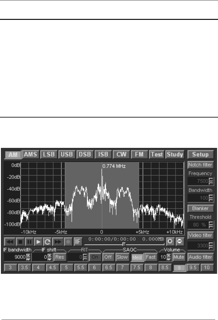
Selecting Demodulation Mode
To select the demodulation mode, click the appropriate mode button in the
demodulator panel:
WiNRADiO G3XX Demodulator Panel
22
WiNRADiO G3XX User’s Manual
In addition to the usual and self-explanatory AM, LSB, USB, CW and FM
modes, there is also AMS (synchronous AM), DSB (dual sideband,
suppressed carrier) and ISB (independent sideband).
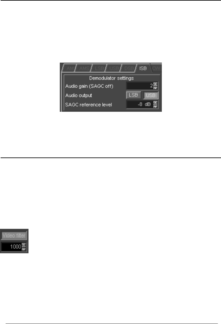
For ISB, the audio output can be selected between the lower and upper side
bands using two selector USB and LSB buttons accessible under the Setup
button:
Note: Both channels of the ISB transmission can be recorded simultaneously
using the recording facility of the G3XX receiver. (In such case, the LSB and
USB signals are recorded as left and right channels of a stereo recording.)
Real-time Spectrum Scope
The real-time spectrum display shows the actual situation within the bandwidth
of the receiver. The actual filter bandwidth is 15 kHz, but the spectrum scope
shows a somewhat wider area of 20 kHz, hence the sloping edges. When you
press the mode buttons, you will note that the central highlighted region of the
spectrum changes its width. This corresponds to the IF (intermediate
frequency) filter bandwidth associated by default with the different modulation
modes. All these default values can be overridden and finely adjusted.
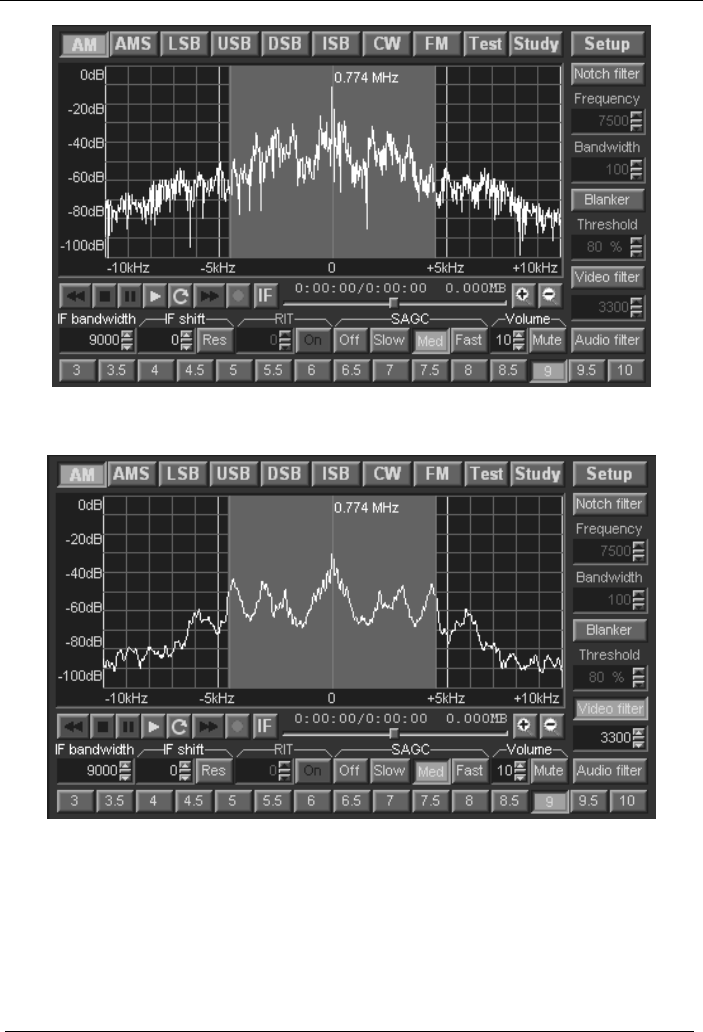
The Video filter is a low-pass filter used to smooth the displayed
spectrum.
When activated, the smoothness of the spectrum trace increases
when the cut-off frequency decreases. The frequency can be adjusted either
by direct typing in the edit box, or by clicking the up/down arrow keys, or, more
conveniently, by dragging the little slider between the up/down keys.
23
WiNRADiO G3XX VHF/UHF Receiver
Spectrum trace without video filter
The same signal with video filter set at 3300 Hz
24
WiNRADiO G3XX User’s Manual
25
The zoom in and out buttons change the displayed signal bandwidth
in 2 kHz steps, while trying to keep the central red marker as close as possible
to the center of the spectrum display. Using the zoom buttons, the displayed
bandwidth can be changed from the default 20 kHz down to 4 kHz, making it
possible to observe small details of the received spectra less than 20 Hz apart.
Setting and Adjusting IF Bandwidth
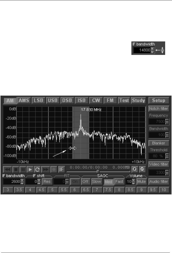
The receiver IF bandwidth can be set in several ways. The quickest way is to
use the IF bandwidth presets represented by the row of buttons at the bottom
of the demodulator window:
The numbers on the buttons represent bandwidth in kHz.
The preset frequencies change according to the mode
selections.
All these frequencies can be changed by the user, for
each mode, using a table of IF bandwidth presets
accessible via the demodulator Setup button.
There are 15 presets, associated with the 15 preset
buttons.
Clicking on the actual number in the Bandwidth column
makes it possible to edit the IF bandwidth value
associated with each button. The button label will then
also change accordingly. Each modulation mode has its
own set of IF bandwidth presets.
To change the IF bandwidth continuously, you can use
the IF bandwidth control in the demodulator panel:
WiNRADiO G3XX VHF/UHF Receiver
There are three ways you can use this control:
• Type the IF bandwidth directly into the edit box, in Hz (type in a number
from 1 to 15000, followed by pressing Enter).
• Use the small up/down cursor keys to adjust the
frequency by 1 Hz steps.
• Use the small slider located between the up/down
cursor keys and move it up or down. This is quite a
fast and convenient method.
Another very convenient method is to adjust the IF bandwidth graphically on
the real-time spectrum display, by dragging the red line bordering the shaded
area representing the IF filter bandwidth:
This method makes it possible to adjust the bandwidth accurately to fit the
actual bandwidth of the received signal, obtain the best signal-to-noise ratio
and minimize interference from adjacent channels.
26

WiNRADiO G3XX User’s Manual
27
IF Shift and Passband Tuning
Dragging the centre red line of the filter passband does not result in the
bandwidth change, but rather moves the entire passband. Such IF Shift
makes it possible to tune the receiver to where the actual signal is, by
positioning the IF filter passband precisely over the real-time signal spectrum.
To use this feature, drag the red vertical line in the middle of the highlighted
filter passband anywhere over a signal peak within the displayed real-time
spectrum. Alternatively, you can use the IF Shift control either by typing the
IF Shift value manually, or using the up/down arrow buttons, or the small slider
between the two buttons: Place the mouse cursor on it and see the cursor
shape change, to indicate a ‘slider’ type of control. To change the IF Shift
value, hold down the left mouse button to drag the slider up or down. To reset
the value back to zero, press the associated Res button.
Note that for the USB and LSB modes, only one of the two filter edges can be
dragged with the mouse. The other edge, which represents the imaginary
“carrier” frequency of the station remains stationary. IF shift is again
accomplished by dragging the centre line. The inactive filter edge is shown in a
darker color.
The IF Shift facility makes it possible to quickly and visually tune to another
station represented by a signal peak in the real-time spectrum. However, it is
not very suitable in the AMS, USB, LSB, DSB and ISB modes if you only wish
to adjust the filter passband position slightly for the station you are currently
receving (for example to avoid interference from an adjacent channel). If you
do this, and are, for example, tuned to an AM station using the AMS mode, or
an SSB station using the USB or LSB modes, then moving away from the
exact carrier frequency will result in a whistle being heard, its pitch being
directly proportional to the IF Shift displacement.
To make it possible to move the filter passband only, but still remain tuned to
the same frequency, there is also an associated Passband Tuning mode:
This is invoked by dragging the graphical centre of the filter passband with the
right mouse button instead of the left one. This makes it possible to finely
adjust the filter position in the AMS, LSB, USB, DSB, ISB or CW modes,
without the whistle effect. Note that in this mode (indicated by “PBT” displayed
in the filter passband) it is not possible to move the filter passband to another
station - simply revert to the normal IF shift mode using the left mouse button
or the IF Shift control, or press the Res button, if you need to move to another
station peak.

WiNRADiO G3XX VHF/UHF Receiver
To summarize, there are two ways to shift the real-time spectrum:
1. IF Shift (without BFO change) which makes it possible to tune the receiver
to another frequency by dragging the entire filter passband over a peak of a
visible signal. Use the left mouse button for this.
2. Passband Tuning (with tandem BFO change), making it possible to adjust
the filter position in SSB and CW modes without detuning the received station.
This is done using the right mouse button.
Volume Control
The Volume control is also located in the Demodulator
panel. The volume can range from 0 (no sound) to 31 (full
volume). To enter a value directly, click on the display and
type in the new volume level. The volume can be also
increased or decreased by clicking on the up/down buttons next to the volume
display.
Another convenient way of changing the volume is by using the small slider
button between the up/down buttons. Place the mouse cursor on it and see
the cursor shape change, to indicate a ‘slider’ type of control. To change the
volume, hold down the left mouse button to drag the slider up or down.
Finally, another convenient way of changing the volume is using the left and
right cursor keys on the keyboard.
Mute Control
Next to the Volume control is the Mute button, which makes it possible to
switch off the audio output quickly. It is faster to use than setting the volume to
zero, with the added benefit of not changing the set volume level. To use the
mute control, simply click on this button. Click again to release.
28
WiNRADiO G3XX User’s Manual
Software AGC
In addition to the usual hardware AGC (Automatic Gain Control), the G3XX
receiver also has Software AGC.
This facility is used to compensate for audio volume changes when the
antenna signals are so weak that the hardware AGC is not yet activated, or
when the hardware AGC is disabled and manual IF gain setting is used
instead.
Think of the Software AGC as an “Automatic Volume Control”, which acts on
the demodulated audio signal, while the hardware AGC acts on the
undemodulated intermediate frequency signal.
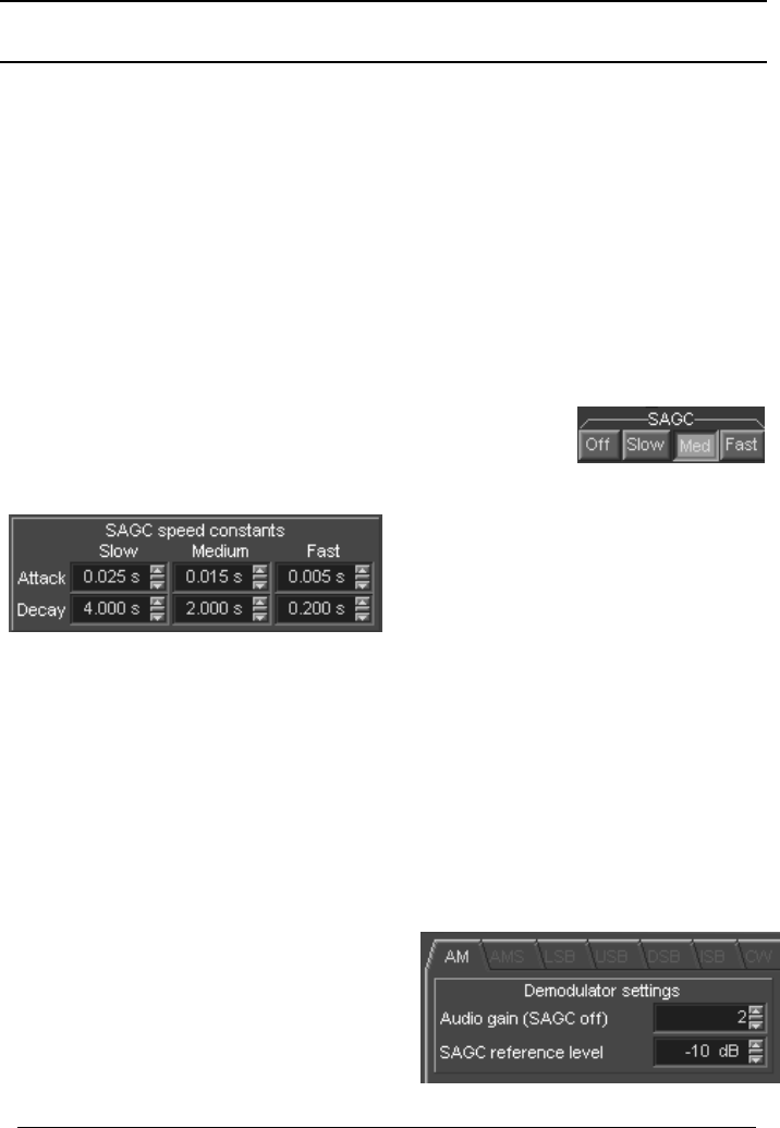
The software AGC has four settings: Off, Slow, Medium
and Fast. These make it possible to disable the AGC, or
to select the speed with which the AGC reacts. Typically,
the AGC would be in the Medium position.
The timing of slow, medium or fast
speed settings is user-definable
under the Setup button:
The attack time (the speed with which the SAGC reacts to a rising signal level)
as well as the decay time (the speed with which the SAGC reacts to a lowering
signal level) can be adjusted separately.
For most practical applications, the medium setting with its default speed
settings is recommended. Slow setting would be used especially with Morse
code (CW mode), while fast setting might be appropriate for very noisy signals
(where noise bursts might temporarily desensitize the receiver if slow decaying
SAGC was employed).
When enabled, SAGC tries to maintain
the audio output at a constant level, the
AGC reference level. This level is user
adjustable under the Setup button,
separately for each demodulation mode:
29

WiNRADiO G3XX VHF/UHF Receiver
The higher the AGC reference level, the louder the maximum audio volume
(which can be then reduced by the volume control). However, with a high level
and strong signal levels there will be a distortion. Decreasing the AGC
reference level will result in lower audio levels.
The Audio gain setting is applicable only when SAGC is turned off, making it
possible to set a fixed gain level (i.e. the maximum volume) for each
demodulation mode separately.
Note:
1. SAGC is available only in AM, CW and SSB modes. (The FM demodulator
audio output is not dependent on the input signal level.)
2. If the receiver volume appears too low (and yet the volume control is all the
way up), make sure that SAGC is enabled.
3. If the sound is distorted despite the volume being turned down, make sure
that SAGC reference level is not set too high.
4. If the sound is too weak when SAGC is disabled (and yet the volume control
is all the way up), use the Audio gain setting to increase the level.
AF Squelch (Audio Filter Squelch)
The AF Squelch is available only for the FM mode. In the absence of an input
signal any FM demodulator produces a strong noise, due to the random phase
variations of received atmospheric noise, and its own receiver noise.
The AF squelch implements a special filter to detect
such noise and compare its level to a preset
threshold. When the noise exceeds this threshold, the
receiver audio is muted.
The threshold level can be set in the AF Squelch edit box, either by direct
typing, using the up/down arrow buttons, or the little slider between the arrow
buttons.
The Noise level indicator displays the actual noise level in a percentage of
white noise contents: zero represents pure signal without any noise, 100
represents pure white noise.
30
WiNRADiO G3XX User’s Manual
This is useful to establish the background noise level when no signal is
received, so that the AF squelch value could be set suitably lower than the
background noise. When a frequency-modulated signal is received, the noise
should drop below the AF Squelch level, which will activate the audio. Note
that the noise level also depends on the IF bandwidth setting: The wider this
setting, the higher the noise level.
Notch Filter
The notch filter is a band-stop filter which can be used to minimize the effects
of interference falling inside or near a received station’s spectrum. The filter is
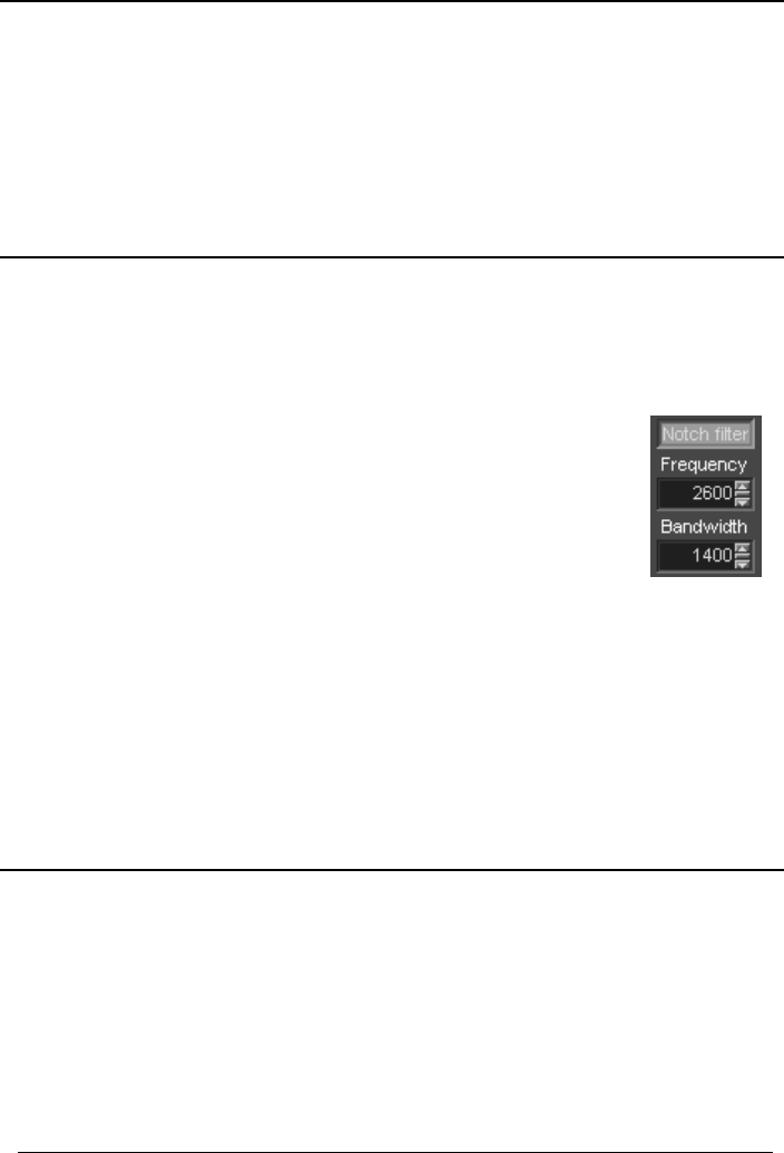
activated by pressing the Notch Filter button. The centre frequency and the
bandwidth can be adjusted using the correspondingly named controls:
For both controls, the same usage rules apply as with the IF
bandwidth setting, i.e. the values can be changed by direct
manual entry, or finely adjusted by using the up/down cursor
keys, or by dragging the slider between them.
Another way of changing the Notch Filter parameters is by
dragging the stopband of the filter (a blue shaded area) with the
mouse.
The stopband width can be adjusted by dragging the edges, while the centre
frequency can be changed by dragging the centre line, which makes it
possible to conveniently position the filter stopband over the interfering signal.
Did you know?
In addition to the above notch filter which operates on the undemodulated
intermediate frequency signal, you can also have audio notch filtering
(including auto-notch) in the optional Advanced Digital Suite plug-in, available
for the G3XX receiver. This also features numerous user-adjustable audio
filters and various other signal conditioning, noise-reduction, decoding and
analysis facilities. See www.winradio.com/ads for more details.
31
WiNRADiO G3XX VHF/UHF Receiver
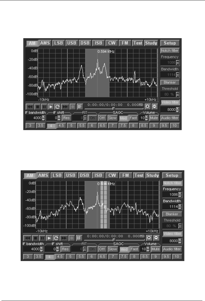
The following picture shows a signal with a strong interference in the passband
(the large peak right of center).
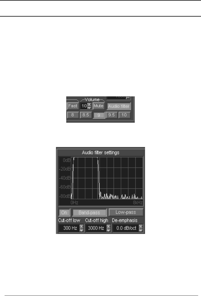
In the resulting audio, typically there would be a strong buzzing sound. After
engaging the notch filter and adjusting its center and bandwidth (by dragging
the blue area center and edges) to fall exactly over the interference, the
situation will look like this:
This results in significantly reduced interference and a much more pleasing
sound.
32
WiNRADiO G3XX User’s Manual
Audio Filter
The Audio filter makes it possible to apply filtering to the demodulated audio.
This is useful in particular for noisy signals, where intelligibility is improved by
emphasizing particular frequencies (usually speech frequencies 300-3000 Hz).
In the FM mode the audio filter is usually necessary to provide de-emphasis of
high frequencies.
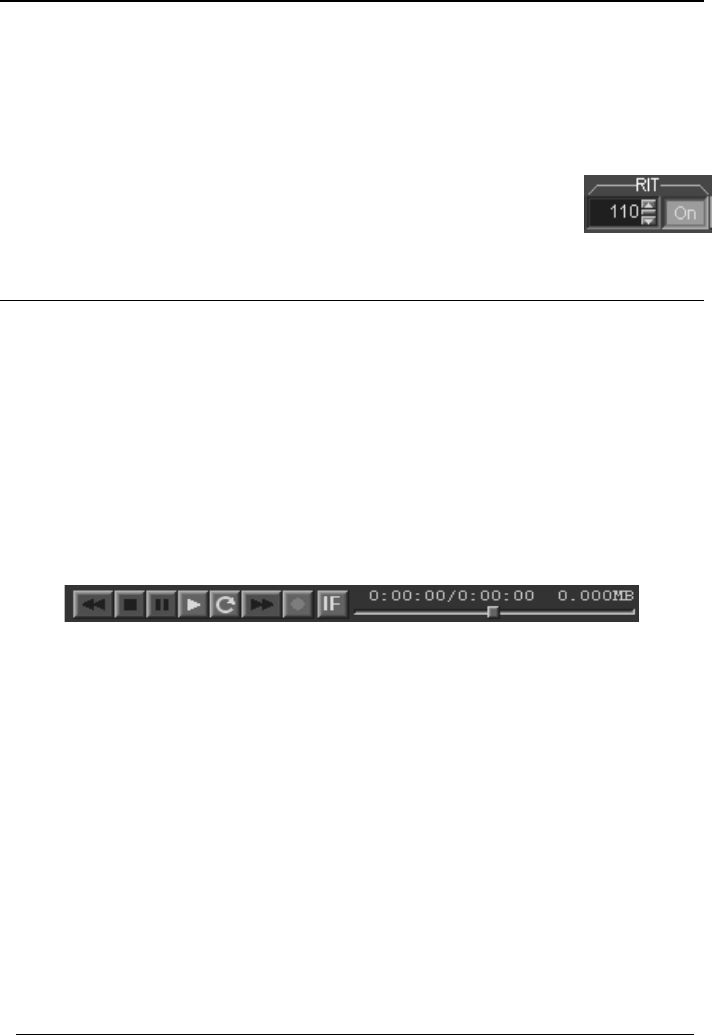
The Audio filter is activated using a button at bottom right of the demodulator
panel:
There two types of filters: band-pass and low-pass, and their parameters can
be adjusted under the Setup button:
The Audio filter settings make it possible to adjust audio filtering parameters
separately for each demodulation mode. The On button either enables or
disables filtering, and is tied to the Audio filter button in the demodulator front
panel.
33

WiNRADiO G3XX VHF/UHF Receiver
The Band-pass and Low-pass buttons make it possible to select the desired
type of filter. The filter cut-off frequencies can be either entered numerically, or
the filter edges can be dragged with the mouse. For the band-pass filter, the
entire passband may be shifted left or right by dragging the top horizontal red
line.
With a band-pass filter, suitable low and high cut off values for good
intelligibility of voice communications are 300 and 3000 Hz, respectively.
De-emphasis is usually necessary for FM demodulation only. The typical
value is -6dB/octave.
Noise Blanker
The Noise Blanker is effective for random high-level noise
spikes, such as atmospherics.
The Noise Blanker is activated by pressing the Blanker button.
If the instantaneous IF signal level exceeds the specified
Threshold level, those IF samples are replaced with older ones. The threshold
level is set as a relative value, a percentage of the maximum possible sample
level.
Receiver Incremental Tuning (RIT)
In some other receivers, this is also referred to as the Clarifier. This function is
used exclusively for SSB (USB or LSB) modes. It is not available, nor
necessary, for other modulation modes.
In effect this is a VFO for IF shift; a short-term memory for IF shift.
If two communicating SSB stations are not exactly on the same frequency,
listening to them may need an adjustment for one of the frequencies,
otherwise one of the stations might sound distorted. To spare you from having
to quickly tune to the new frequency while listening to the dialogue, the RIT
function makes it possible to conveniently adjust the frequency increment by
simply engaging or disengaging the RIT button.
34
WiNRADiO G3XX User’s Manual
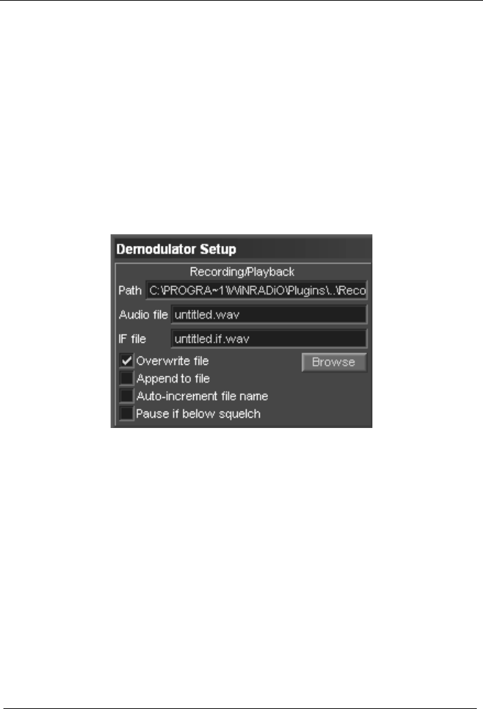
To set up RIT, firstly tune the receiver precisely to one of the stations, until you
have perfect sound. Then press the RIT button and adjust the RIT frequency
increment (it is shown in Hz) to hear the second station clearly. You can either
type the increment value in the edit box (which is a slow way), or use the
up/down arrow keys, or the small slider located between the arrow keys, which
is the fastest way.
Then simply turn RIT on and off, depending on which station is
currently on air.
Recording and Playback
The G3XX receiver’s demodulator has integrated recording and playback
functions. This facility makes it possible to record and playback the
demodulated audio in standard “.wav” files, as well as the modulated signal at
the IF level (IF recording).
The IF recording feature can be very useful in situations where the received
signal is of some significance and needs to be analyzed. A weak or
interference-obscured signal can be thus “re-received” with different
bandwidths, notch filter and noise blanker settings, to arrive at the best
possible demodulated audio.
Recording starts when the Recording button (with red dot) is engaged, and
stops when the Stop button (green square) is pressed. The Pause button (two
green vertical lines) is also available.
Playback is done by pressing the Play button (green arrow), and the Fast
Backward and Fast Forward buttons complement the recording controls.
When the IF button is engaged, the recorder will record on the IF level instead
of audio. The recorded files will have the extension “.if.wav”.
The round arrow button, when engaged, causes an infinite looping when
playing either audio or the IF signal: When the recorded signal reaches the
end, the playback will restart immediately again from the beginning. This is
particularly useful when you are playing back an IF signal and experimenting
with different settings of filters for the best possible audio quality.
35
WiNRADiO G3XX VHF/UHF Receiver
The recorder uses fixed “wav” file formats:
1. For audio recording (except in ISB mode): 16 kHz sampling rate, 16-bit
mono
2. For audio recording in the ISB mode: 16 kHz sampling rate, 16-bit stereo
3. For IF recording: 64 kHz sampling rate, 16-bit, mono
The recording/playback set-up is done using a dedicated section in the
Demodulator settings (under the Setup button):
The recorded file path can be set up using the Path edit box. The default file
names for recording/playback can be set up using the Audio file and IF file
edit boxes, for Audio files and IF files, separately. The directory Browse button
can be used to advantage, instead of typing the path and file names.
The audio and IF file names are related; the only difference is the “.if” used
before the “.wav” extension for the IF files.
For recording, there are three possible options to choose from:
Overwrite file - the file, if it exists, is completely overwritten with new samples.
Append to file - the new samples are appended to the file, if it already exists.
36

WiNRADiO G3XX User’s Manual
37
Auto-increment file name - each time the record button is pressed, a number
just before the “.wav” extension, and “.if” for IF files, is incremented; if there is
no initial number, 1 is automatically used first.
Normally, the recording does not depend on the squelch. However, if the
option Pause if below squelch is activated, the recording will pause
accordingly.
The path and the file names for audio and IF recording can be both manually
edited or configured using a dedicated dialog box shown by clicking on the
Browse button. The audio and IF file names are correlated, the only difference
being the ".if" used before the ".wav" extension.
The file names can contain "wildcards" which make it possible to include date,
time, frequency, etc., inside the name of the file. The following wildcards are
supported:
#D - system date (in YYYYMMDD format)
#T - system time (in HHMMSS format)
#F - frequency in MHz (6 decimals)
#M - mode - ("AM","AMN","AMS","DSB","USB","LSB","ISB","CW","FMN")
#N - serial number of the receiver
For example, the following is an acceptable file name, where the date, time
and frequency will be included:
myfile #d #t #f.wav
Recoding is also possible while the receiver is scanning and searching for
stations. To take advantage of this feature, enable Pause if below squelch,
set up a file name which includes the #F frequency wildcard, and start
scanning. Depending on the scanning parameters, the receiver will then record
the intercepted station audio or IF samples to “wav” files. For example,
if Pause if signal appears is enabled, and the Pause delay is set to 10
seconds, then samples of 10 seconds each will be recorded – see the
Scanner Configuration chapter for more information.
WiNRADiO G3XX VHF/UHF Receiver
Test and Measurement
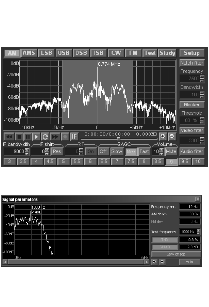
The Test and Measurement function of the G3XX receiver is invoked by
pressing the Test button:
This causes an instrumentation window to open which contains several
facilities to assist with analysis and measurement of the received signal:
The real-time Audio Spectrum Analyzer on the left of the window makes it
possible to observe properties of the demodulated signal with a 5 Hz
resolution.
38

WiNRADiO G3XX User’s Manual
39
The red marker can be dragged with the mouse and the associated frequency
and level observed at the top of the marker. To zoom the spectrum graph in
and out, use the zoom buttons on the left of the Help button.
The Frequency error display indicates the frequency error of the received
signal (presuming the receiver is tuned to the correct frequency).
The AM depth display measures depth of amplitude modulated signals.
The FM deviation display shows frequency deviation of frequency modulated
signals.
The THD and SINAD buttons enable the measurement of Total Harmonic
Distortion and SINAD (signal-plus-noise-plus-distortion to noise-plus-distortion
ratio), respectively. The test frequency for these two functions (which should
be equal to the modulating audio frequency applied to the RF test signal
connected to the antenna) can be adjusted using the Test frequency edit box.
The Stay on Top button can be used whenever it is convenient for the test and
measurement window to remain on top of all other windows.
Did you know?
Using the SINAD measurement facility and a calibrated signal generator, you
can measure the receiver sensitivity very easily. For example, to measure AM
sensitivity, connect the signal generator to the antenna input and turn on AM
modulation (the modulation depth is usually set to 30%, although some
manufacturers prefer to quote sensitivity figures at higher modulation depths,
for example 60 or 80%). Set the Test frequency equal to the modulating
frequency (typically 400 Hz or 1 kHz). Adjust the IF bandwidth for the
maximum SINAD. Then gradually keep reducing the generator output level to
the point when SINAD drops to 10 dB. The receiver sensitivity is then equal to
the generator level at this point. Measuring AM sensitivity using SINAD rather
than the conventionally used S+N/N is quite appropriate as SINAD also
includes distortion, which is as much an impediment to intelligible reception as
noise, and therefore provides a more practical result. Even though in theory
using SINAD should result in the sensitivity figures being somewhat worse
than if S+N/N is used, in practice, with a good receiver such as the WR-G3XX,
there is not a noticeable difference.
WiNRADiO G3XX VHF/UHF Receiver
Demodulator Structure
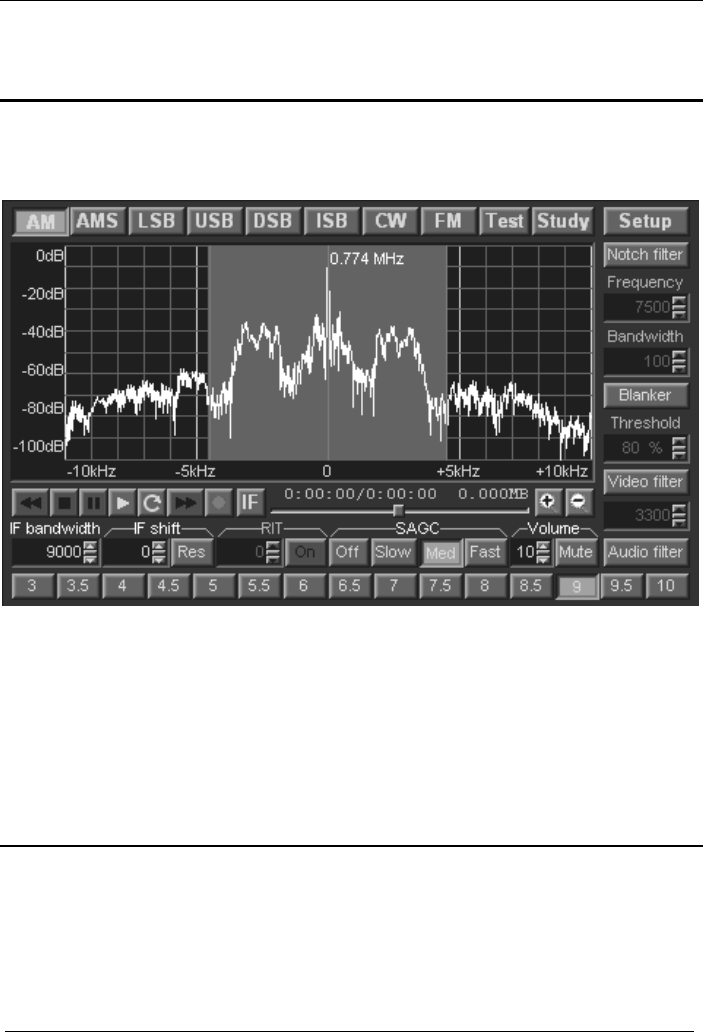
The structure of the G3XX demodulator can be accessed and explored using
the Study button:
The study button reveals the internal structure of the currently selected
demodulator, with additional measurement facilities.
This function is intended for users wishing to acquaint themselves more deeply
with Software Defined Radio principles. It is described in greater detail in
Appendix E – Inside G3XX Demodulator.
Did you know?
The award-winning WiNRADiO G303i receiver was the world’s first software-
defined commercially available receiver.
40
WiNRADiO G3XX User’s Manual
Other Demodulator Settings
Amongst the last remaining demodulator settings are Mute audio on exit and
Show frequency in kHz, located at the bottom left of the demodulator Setup
panel.
As all critical demodulation functions are performed inside the on-board DSP,
the receiver can continue playing audio even when the application is closed,
as long as power is supplied to the board. Check the Mute audio on exit
checkbox if you wish for the audio to be muted when the application is closed.
This facility is available only on the internal (G3XXi) model; with the G3XXe
model, the audio cannot continue once the application is closed.
Show frequency in kHz applies to the frequency displayed next to the marker
in the demodulator real-time spectrum display. If this is unchecked, the
frequency will be displayed in MHz. This is independent from the main
frequency display, which is governed by the kHz and MHz buttons located
next to the main display.
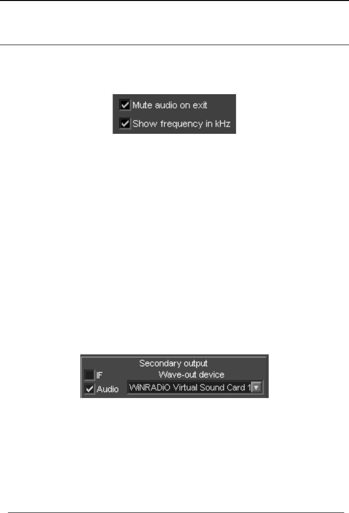
The Secondary output can be applied to IF or audio signal. It is intended for
third-party applications that require access to the digitized IF or audio samples
for further signal decoding. The IF samples are passed at 48 kHz sampling
rate, two channels. Audio samples are passed at 16 kHz, one channel.
The Secondary output can be used to advantage by the optional WiNRADiO
Virtual Sound Card software, which makes it possible to pass the digitized
signals from the receiver directly to a third-party application without any
intervening re-digitization process and therefore without introducing any
additional distortion to the received signal. Alternatively, it is also possible to
use this feature to provide an output to a secondary (real) sound card.
41
WiNRADiO G3XX VHF/UHF Receiver
Receiver Gain Control
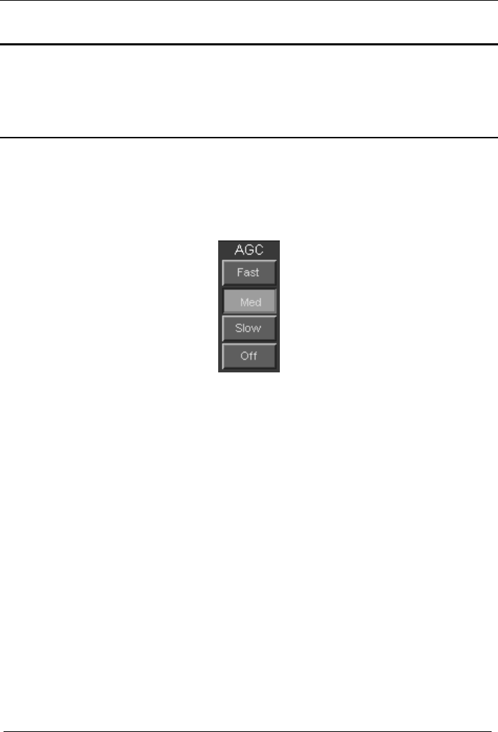
There are three hardware controls related to the receiver gain: AGC, Manual
IF Gain and Attenuator.
AGC
The receiver must process a considerable variation of signals, ranging from
very weak to very strong. This requires the sensitivity of the receiver to vary
according to the incoming signal strength. This can be done automatically
using AGC (Automatic Gain Control) or manually, using manual IF Gain
control.
The incoming signal can vary in intensity, with changing propagation
conditions, and also depending on the modulation type and content. For
example, with CW signals (where information is transmitted by keying the
transmitter on and off), the signal strength will vary substantially during the
transmission. The demodulated signal will then sound better with a slow AGC
(as the receiver will not have time to increase the gain during the “off”
intervals, and increase the background noise and causing a raspy sound).
On the other hand, use fast AGC when listening to especially weak signals
buried in static and noise. Otherwise, each new burst of noise would
desensitize the receiver for a long time and you could miss long periods of
useful transmissions. If unsure, use the medium speed AGC setting.
It is easy to forget that AGC has been disabled. If the signal sounds distorted,
or, on the other hand, sensitivity appears to be very low, check the AGC
setting first.
42
WiNRADiO G3XX User’s Manual
IF Gain Control
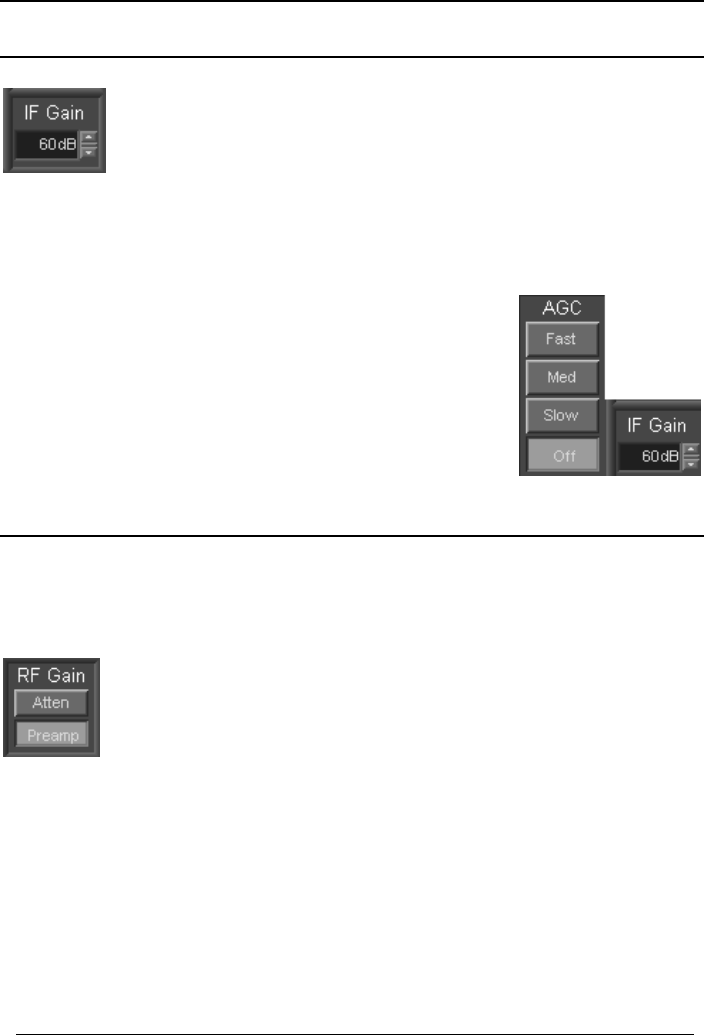
The AGC can be turned off using the AGC Off button. The
receiver gain must then be adjusted manually. This is done using
the IF Gain control.
Note that by setting an excessive gain, the receiver will overload
and the demodulated signal will be distorted, which can be very easily
observed in the real-time spectrum scope. On the other hand, if the gain is too
low, it will make the receiver appear “deaf”.
Manual IF Gain setting is very useful when hunting for
very weak signals buried in noise. The IF Gain control is
only enabled when the AGC is switched off.
The gain can be adjusted in three ways: by typing the
value directly in the edit box, by using the up and down
buttons, or by dragging up or down the centre slider
button.
RF Gain Control
The Attenuator, when enabled, makes it possible to reduce the receiver
sensitivity by 18 dB. The Preamplifier, when disabled, reduces front-end gain
by further 12 dB.
By attenuating the input signal and/or reducing the front-end
preamplifier gain, the sensitivity of the receiver is reduced to
avoid overloading by strong signals (e.g. from local broadcast
stations).
If sensitivity appears poor, please make sure that the attenuator is disabled
and the preamplifier is enabled.
43

WiNRADiO G3XX VHF/UHF Receiver
Squelch Control
The Squelch control can be used to mute the receiver when no signal is
being received. Without a signal, all you will usually hear is noise. Squelch is
provided to cut out the noise until a station is found, making the receiver more
comfortable to use.
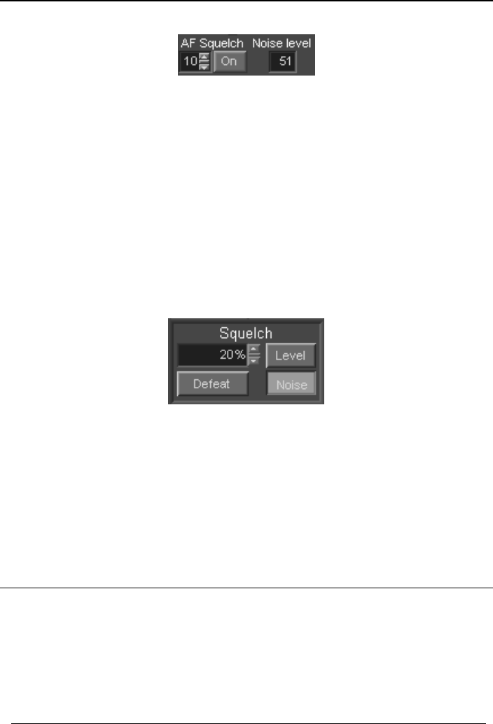
There are two types of squelch in the G3XX receiver: Signal level squelch
(selected by the Level button) and Audio noise squelch (selected by the
Noise button).
The Level squelch setting controls the signal level (in dBm) at which muting
occurs. Muting will occur when the signal level drops below the preset squelch
value. When a signal of a higher level returns, the sound will be restored
immediately.
To adjust the squelch control, first tune to an unoccupied frequency that
produces only noise. Increase the squelch until the receiver is muted. You will
see the red-colored segment of the S-meter growing until it gets higher than
the current S-meter value. At that moment the receiver will be muted. Add a
few dB extra (to allow a margin for background noise fluctuation on the band).
Now when you tune to an occupied frequency, if its signal strength is higher
than the squelch level, the receiver will be unmuted.
The Noise setting makes it possible to mute the receiver depending on the
contents of noise in the demodulated signal, and is typically only used in the
FM mode. As the FM demodulator produces strong noise when no signal si
being received, a special filter is used to detect such noise and its level
compared to the specified value. When the noise exceeds this specified value,
the audio is muted. The Noise value is entered as a percentage of white noise:
Zero value signifies a clean signal, while 100% corresponds to pure white
noise (no useful signal). The actual noise level is displayed in the demodulator
panel, alongside the AF Squelch control:
44
WiNRADiO G3XX User’s Manual
While both the main panel Noise Squelch and the demodulator AF Squelch
act upon the same signal, their usage is slightly different: If the main panel
Noise Squelch is set, this also automatically sets the demodulator AF Squelch.
On the other hand, when the demodulator AF Squelch is set, this does not
automatically set the main panel Noise Squelch. This is because the main
panel squelch is also used for scanning purposes, while the demodulator AF
Squelch can only mute or un-mute the audio. So, it is possible for the scanning
to be controlled by the Level Squelch, but the audio muted by the
demodulator’s AF Squelch.
Note that the noise level also depends on the IF bandwidth setting: The wider
this setting, the higher the noise level. A typical Noise Squelch value for
scanning of point to point communications is approximately 30-50%.
Next to the squelch setting is the Squelch Defeat (Def) button. When
activated, the squelch action will be turned off (it is the same as if the squelch
was set to its lowest level, but more convenient). The red segment in the S-
meter will turn blue to indicate this condition.
It is easy to forget that squelch is active. If the receiver doesn’t seem to be
operational (no sound from the speaker), check the squelch and mute settings
first.
Did you know?
Squelch can be also controlled by the signal contents. For example, the
CTCSS (Continuous Tone Coded Squelch System) is also supported by the
optional WiNRADiO Advanced Digital Suite (see www.winradio.com/ads).
45
WiNRADiO G3XX VHF/UHF Receiver
Memory
The WiNRADiO G3XX receiver has the ability to store up to ten thousand
frequencies in one memory file. It makes it possible to load and save different
memory files for a huge amount of total storage, limited only by the size of the
PCs hard disk.
Storing a Frequency into Memory
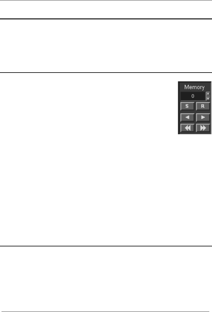
With each frequency, you can store several attributes: mode,
call sign, user comment, group assignment, squelch and a
hotkey.
To store a frequency into memory, the receiver must first be
tuned to that frequency (and the appropriate mode must be
selected if you also wish to store the mode). Next click on the S
button in the Memory Control Panel as shown above.
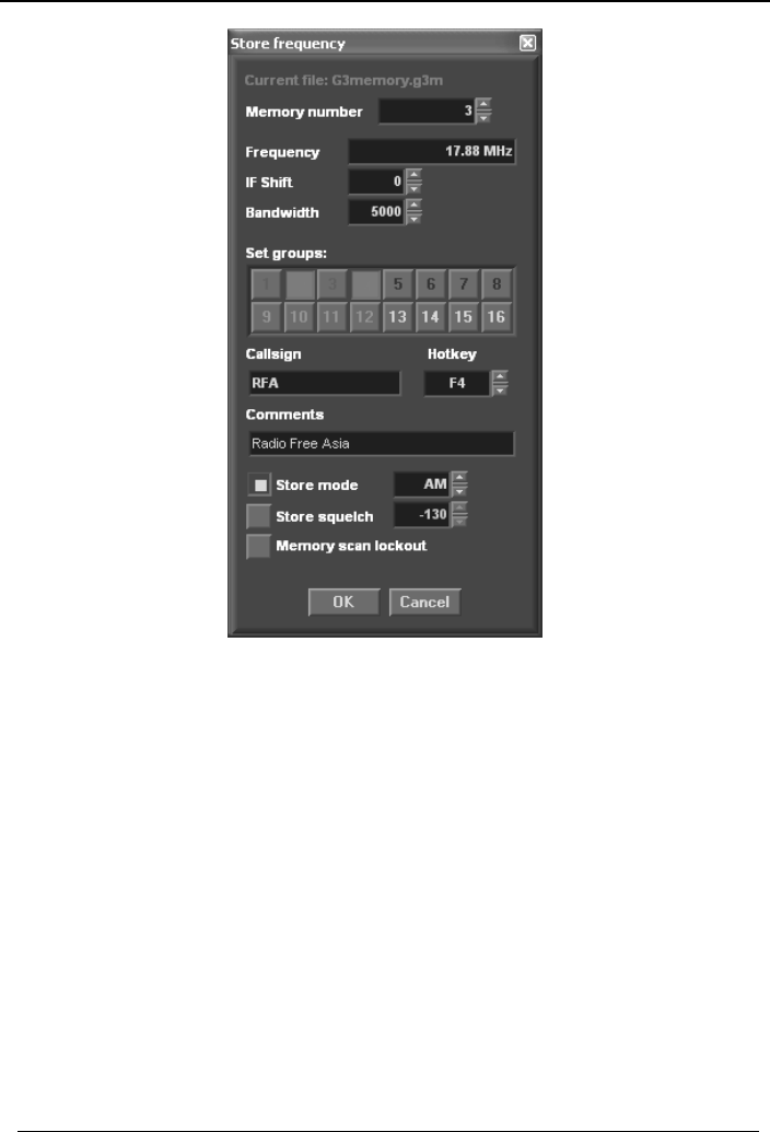
A Store frequency dialog box will pop up, making it possible to assign a
memory number to the current frequency.
Note: The default memory file is called G3memory.wgm and resides in the
same path as the WiNRADiO receiver application, i.e. usually in the
C:/Program files/WiNRADiO/G3XX/ folder.
Did you know?
There are a number of WiNRADiO utilties and plug-ins dedicated to
processing and manipulation of memory files. In addition to storing frequencies
in memory files, you can also have databases, which are suitable for a larger
number of frequencies. For more details of available applications related to
memories and databases, please refer to www.winradio.com/software.
46
WiNRADiO G3XX User’s Manual
At the top of the dialog box is the current memory file name into which you are
storing (you can have as many different files as you like). The next line shows
the allocated memory number. You can change this to another memory
number if you wish (including one which is already allocated).
Then follow the current frequency, IF shift and bandwidth parameters. You can
alter these if you wish.
The third item contains the group assignment buttons. You can assign the
frequency to one or more of 16 different groups (whose meaning you define
yourself). When you are searching or scanning for a particular type of
frequencies (for example “Airforce”), the group assignment will allow you to
confine the searching and scanning to that particular type.
Note that a particular frequency may be associated with more than one group
at the same time.
47

WiNRADiO G3XX VHF/UHF Receiver
48
There are also several additional items that can be optionally stored with each
frequency:
• Most stations have a name or call sign. You can store up to 11 characters
in the Call sign field.
• For quick tuning to your favorite stations, you can assign Hotkeys
(function keys F2 to F12) to up to eleven different frequencies. If you then
press a hotkey, the associated frequency will be instantly recalled.
Hotkeys which are already assigned will be shown in this dialog box as
‘used’, however you can overwrite the previous assignment with a new
one if you wish.
• User Comments can also be stored with a frequency. The size of the
comments is limited to 31 characters.
• The Mode and Squelch values can also be stored, which will then be set
automatically when the frequency is recalled.
• Finally, a Memory Scan Lock-out can be set for each memory, which
means that the memory will not be included in a memory scan. In the
memory Recall window, such memories will be shown with a small ‘x’
preceding the memory number.
Finally, when everything has been set, click on OK or press Enter, to save the
new frequency.
Recalling a Frequency from Memory
There are several ways to recall a frequency from memory:
• Using Memory Recall
• Typing a number into the memory number display
• Using a hotkey
• Memory stepping
To recall a frequency, click on the R button. A dialog box will pop up showing
a list of all memory frequencies.
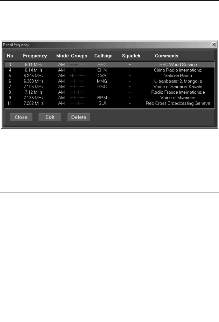
WiNRADiO G3XX User’s Manual
To select a frequency, click on an item in the list, and the frequency will be
tuned. Then close the window. Alternatively, use the up or down cursor keys
to choose the frequency and press Enter.
The assigned memory groups are shown as color bars for a quick visual
overview of which frequencies are associated with which groups (see the
corresponding colors in the Store frequency window). When you position the
mouse cursor over a highlighted memory, the actual group numbers will be
displayed in a floating ‘hint’ box.
Editing Memory
To change the settings for a particular frequency, open the Recall frequency
dialog box as described in the previous section. Select the item you want to
edit and click on Edit (alternatively, double-click on the item). A dialog box will
pop up showing the current settings. All the settings, except the memory
number, can be edited. After the entry has been edited, click on OK.
Deleting a Frequency
To remove a frequency, open the Recall frequency dialog box. Select the
frequency you wish to delete, and click on Delete. You will be asked to
confirm that you want to delete this frequency from memory. To delete all
frequencies, select Clear from the Memory file sub-menu in the File menu.
You will be asked to confirm that you want to clear all the frequencies in the
memory.
49

WiNRADiO G3XX VHF/UHF Receiver
50
Saving a Memory File
Each memory file, containing up to one thousand frequencies, is stored
separately, allowing different memory files to be loaded and saved. To save
the current memory file, simply select Save from the Memory file sub-menu in
the File menu. If you wish to save it with a different name, select Save as
instead, and a dialog box will pop up allowing you to specify the file name.
When you exit the WiNRADiO G3XX application, all memory changes are
automatically saved; there is no need to use the Save command before exit.
Opening a Memory File
When the WiNRADiO receiver application starts up, the most recently used
memory file will be opened automatically.
To open a different memory file, select Open from the Memory file sub-menu
in the File menu. A dialog box will pop up allowing you to choose a memory
file to load.
Memory Stepping
Memory stepping makes it possible to step through frequencies stored in the
current memory file.
To step through memory frequencies use the left or right arrow buttons located
under the memory S and R buttons. The double-arrow buttons located further
down make it possible to advance ten frequencies up or down (or to the start
or end of the memory list if it is less than ten frequencies away).
Memory stepping will only work if there are frequencies stored in memory. If
no frequencies have been stored, nothing will happen if you try to step through
the memory.

WiNRADiO G3XX User’s Manual
Scanning
The WiNRADiO G3XX application contains a comprehensive set of scan
functions to enable the user to search for stations which are currently on the
air. There are three basic types of scanning: Immediate Scanning
(Searching), Range Scanning and Memory Scanning. The scanning method
is selected using the appropriate button in the Scanning Control Panel:
Immediate Scanning (Searching)
This is the simplest scanning method. Click on the Search button to select
this scanning mode, then use the [>>] or [<<] buttons to scan either forward or
backward from the currently tuned frequency. To stop scanning, press the
Stop button (marked with a green square). To pause, press the Pause button
(marked with two vertical bars).
If you are using the Signal level type of squelch, then a signal is considered
‘found’ when the signal level becomes higher than the squelch level. If you set
the squelch level too low, scanning will stop even if there is no signal (the
background noise peaks will exceed the squelch level). On the other hand, if
the squelch level is set too high, then a useful signal may be missed because
it will fall short of the squelch level. Correct setting of the squelch value is
therefore essential for scanning. With a bit of trial and error, you will need to
adjust the optimum setting for the squelch level (usually a few dB above the
background noise floor).
With Noise squelch (which is especially recommended for use in FM mode),
the signal will be ‘found’ if the receiver finds a channel where the audio is less
noisy, i.e. when the audio has been quietened by receiving an FM modulated
signal and the noise level has fallen under the preset limit. The optimum
setting varies, depending on the IF bandwidth (the wider the bandwidth, the
higher will be the setting, because the noise on an unoccupied channel will be
also stronger).
51
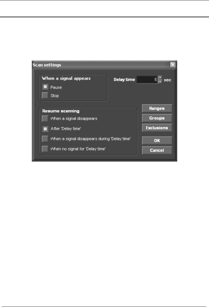
WiNRADiO G3XX VHF/UHF Receiver
Scanner Configuration
When a signal strength level is higher than the squelch level, this indicates that
a signal has been found. You can configure the software to specify what action
you want to be taken at this point. To access this configuration facility, go to
Options | Scanning in the top bar menu.
There are two basic actions the software can do when a signal is found:
Pause scanning or Stop scanning. If Pause is selected, then you need to
further specify the conditions under which the scanning will Resume. The
conditions to resume can be one of the following:
• When the signal disappears (i.e. the scanning resumes immediately when
the signal disappears);
• After a user-defined Delay time (i.e. no matter if the signal disappears
during this Delay Time or not, the software will always wait for the Delay
Time interval, then resume scanning);
• When the signal disappears during Delay time (i.e. the scanning will not
resume if the signal returns within an interval shorter than, or equal to,
Delay Time);
• When there is no signal during the Delay time (i.e. the scanning will
resume if there is a no-signal gap equal to, or longer than, Delay time).
• The Delay time interval can be set from 1 to 100 seconds.
52

WiNRADiO G3XX User’s Manual
53
The scanning speed is determined by the scanning step size. The scanner
tunes the receiver in increments of 10 kHz and uses 10 kHz wide “chunks” of
the IF spectrum to search for a signal. If the step size is 10 kHz, the typical
scanning speed will be approximately 40 channels per second. If the step size
is 5 kHz, then the scanner only needs to retune the receiver once per every
two steps, which results in a nearly double the effective scanning speed. For 1
kHz steps, the effective scanning speed will be approximately 400 channels
per second.
Note that the maximum scanning speed may be limited by the actually
available CPU resources of your computer.
When a signal is found and scanning pauses, waiting for the pre-set Delay
time to expire, the countdown timer will appear inside the [<<] or [>>] buttons.
If no Delay time was set and scanning is pausing until the signal disappears,
then the [<<] or [>>] button will flash.
Groups
The Groups setting is useful for Memory Scanning, which will be described
in detail later: it serves to restrict Memory Scanning to particular memory
groups only.
Exclusions
Sometimes it is desirable to exclude certain frequencies from scanning. This
means that such specified frequencies should be ignored, even if the signal
level on these frequencies is higher than the squelch.
The WiNRADiO G3XX receiver application makes it possible for multiple
frequency ranges to be excluded. This is done using the Exclusions button.
When you press this button, you will open an Exclusions editor window,
allowing you to enter a range of frequencies to be excluded.
For these exclusions to become active, check the Enable excluding while
scanning checkbox in this window.
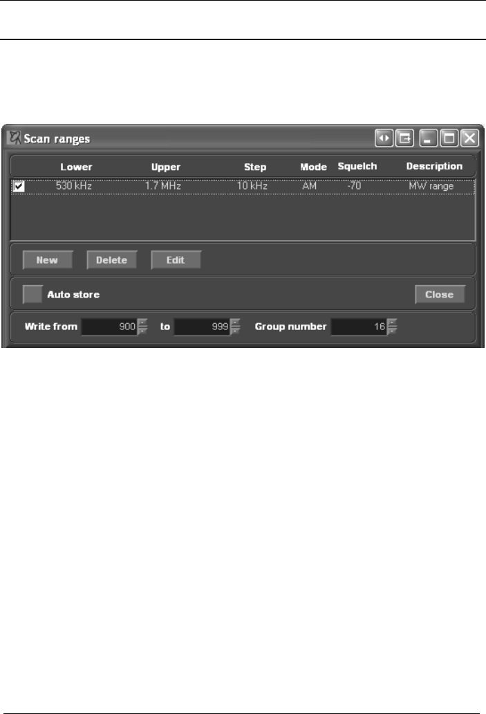
WiNRADiO G3XX VHF/UHF Receiver
Frequency Range Scanning
To be able to use Frequency Range Scanning, you need to set up the desired
scanning ranges first. This is done using the Ranges button in the Options |
Scanning top-bar menu.
Note the check box at the start of a range. This is useful in situations where
you may have several ranges defined, and you wish to enable only one or
several from the list, without the need to redefine the whole range list each
time you want to make change in one range only. Use the checkbox to select
the particular range(s) you wish to include in range scanning.
A very useful feature of frequency range scanning is that all found frequencies
can be automatically stored in memory, even if the receiver is left unattended.
To do this, enable Auto Store and specify the memory number range to
which the frequencies should be written. You can also specify a special Group
Number to be assigned to such frequencies.
When using the Auto Store option, you should also set the appropriate
conditions in Scan Settings to take effect when the signal is found. For
example, Pause when signal appears, and Resume after the minimum delay
time will provide the fastest scanning and writing into memory). Note that if
more signals are found than there are allocated memories, the excess
frequencies will not be stored.
54
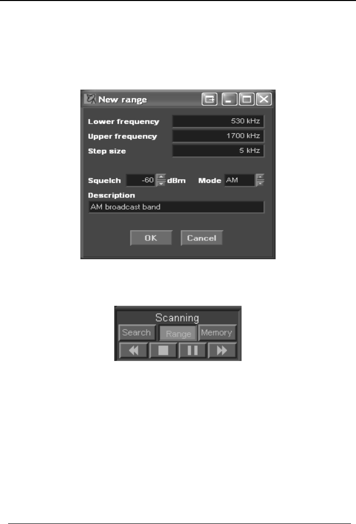
WiNRADiO G3XX User’s Manual
To create a new range, click the New button. This will open a dialog box,
where you can specify lower and upper limit frequencies of the range, the step
size, modulation mode, squelch level, and, optionally, a description. You can
enter as many such ranges as you like.
When the range definition is done, close this window, then close the scanner
settings. Then activate the Range button in the Scanning control panel:
When you press the Scan Forward button [>>], the scanner will commence
scanning from the start frequency of the first range. When the last frequency of
the first range is reached, it will then continue onto the next range, etc. When it
reaches the end of the last range, it will go back to the start of the first range
and continue looping infinitely until a signal is found, or until manually stopped
or paused. If you use the Scan Backward [<<] button, the process will be
exactly reversed (i.e. starting from the top frequency of the last range and
working its way downwards).
55

WiNRADiO G3XX VHF/UHF Receiver
56
You can stop or pause this activity using the Stop or Pause buttons. If you use
the Pause button, then restarting scanning using Scan Forward or Scan
Backward buttons will resume the action from the paused frequency. If you
stop scanning with the Stop button, then using the Scan Forward or Scan
Backward buttons will recommence scanning from the initial (or the last)
frequency again.
If no ranges are specified in the Ranges list, then activating scanning in the
Range mode will result in no action.
Memory Scanning
The last scanning method is Memory Scanning. Here the receiver will step
through memory frequencies, starting with the first one to the last one, and
repeating the loop until a signal is found or until manually stopped.
If a squelch value is stored with a memory, this value will then be used to
compare with the current signal level. If there is no value stored, the current
squelch value will be used as the scanning threshold.
It is possible to restrict scanned frequencies to particular memory groups only.
These groups can be selected from the Options | Scanning | Groups
window, accessible from the top bar menu. Groups can be enabled/disabled
using the check box Enable group restriction in the same window.
Note: Typical scanning speed for memory scanning is 40 channels/second.
This can be significantly reduced for frequencies which are close to each
other. For example, if the next frequency is closer than 10 kHz to the previous
one, and the specified bandwidth also falls within this 10 kHz distance, then
the receiver will not need to tune its hardware to the new frequency. Instead, it
will tune to the new frequency by software processing of the received
spectrum. This will result in tuning to the new frequency much faster. If
scanning speed is important, it is also advisable to sort the memories by
frequency, because the larger the tuning step, the longer it takes for the
receiver to settle on the new frequency.
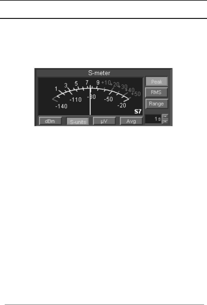
WiNRADiO G3XX User’s Manual
S-meter
The WiNRADiO G3XX receiver is equipped with a very sensitive and selective
Signal Strength Meter (S-meter) which makes it possible to measure peak or
RMS signal level dBm, µV or S-units, within the IF filter passband. The
measurement units are selected by appropriately marked buttons at the
bottom of the display.
The S-meter also shows the currently selected value of the squelch (the red
section at the bottom side of the scale). When the signal strength falls under
the squelch level (i.e. the needle falls in the red region and turns red also), the
receiver audio will be muted.
The squelch value is always indicated in dBm (even if the signal strength is
displayed in S-units or microvolts).
The Peak and RMS buttons select between peak and RMS values (calibrated
for sine wave modulation).
The S-meter is very selective, and acts only upon signals within the actually
selected IF bandwidth (shaded area in the real-time spectrum display). The
Range button splits the S-meter “needle” into two, and makes it possible to
observe the dynamic range of the input signal (i.e. the minimum and the
maximum values within the signal bandwidth):
57
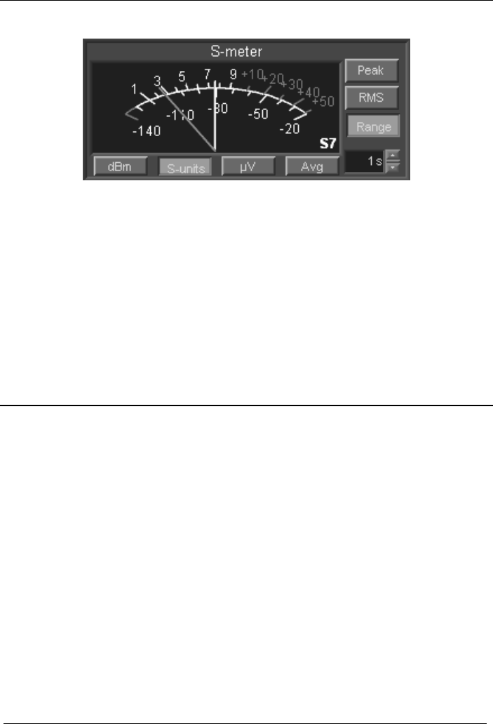
WiNRADiO G3XX VHF/UHF Receiver
The Avg button, when activated, shows the S-meter level value as a floating
average within the preset time interval (settable from 1 to 99 seconds). This is
used to smooth the S-meter movements. Any change which may affect the
S-meter value (such as tuning the receiver to a new frequency or changing the
attenuator setting), resets the averaging interval, so that the S-meter may
react immediately to such change.
Note: The S-meter relies on the AGC for its proper operation. Therefore, if the
AGC is switched off and manual IF gain is used instead, the S-meter is also
disabled.
Did you know?
There are no exact definitions for S-units, merely recommendations.
Historically, the S-units referred to subjectively perceived signal strength as
follows:
S1… faint signals, barely perceptible
S2… very weak signals
S3… weak signals
S4… fair signals
S5… fairly good signals
S6… good signals
S7 …moderately strong signals
S8 …strong signals
S9… extremely strong signals
58
WiNRADiO G3XX User’s Manual
Nowadays, most manufacturers, including WiNRADiO, usually implement the
ARRL recommendation where the S-units are spaced 6 dB apart and S9
corresponds to 50 µV at a 50 ohm antenna input, or -73 dBm (on HF bands).
Power Switch
The Power switch, located at the bottom-right corner of the application
window, controls the receiver power. When it is off, the receiver circuitry will be
powered down and no sound will be heard through the speaker or
headphones.
When you exit and restart the WiNRADiO application, the power on/off status
at exit will be remembered.
Date and Time Displays
The clock display indicates the current time and date.
The UTC clock shows Universal Coordinated Time, formerly called GMT
(Greenwich Mean Time), which is the standard time used around the world.
This is provided because most shortwave stations announce their broadcast
times in UTC. Both displays derive their information from the PC clock. The
time difference is determined by Windows Time Zone setting (Start | Settings
| Control Panel | Date/Time Properties | Time Zone tab).
59
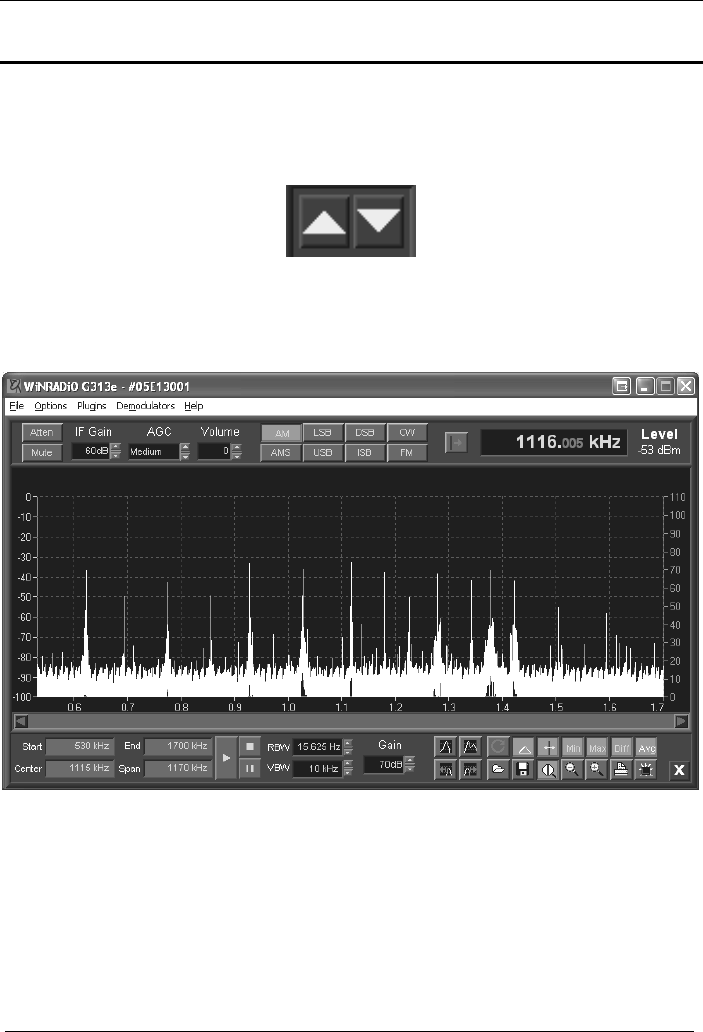
WiNRADiO G3XX VHF/UHF Receiver
Spectrum Analyzer
There are two different versions of a Spectrum Analyzer in the G3XX receiver
software. These are selectable by clicking one of the yellow triangle buttons on
the left of the On/Off switch. The Spectrum Analyzer display will slide out.
If the upward pointing arrow button is pressed, the large sized full-screen
spectrum scope will slide out upwards, entirely obscuring the receiver main
control panel:
If the downward pointing button is activated, the spectrum analyzer will slide
downwards, and will remain attached to the bottom of the receiver control
panel, without obscuring it:
60
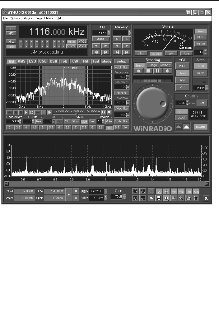
WiNRADiO G3XX User’s Manual
This smaller version of the spectrum analyzer window can be resized to a
convenient size by dragging the bottom edge up or down.
The bottom parts of both spectrum analyzer windows are exactly the same.
The full-screen version also contains a basic set of the receiver controls at the
top, so that the user does not need to go back to the receiver panel to change
mode, volume, attenuator, etc.
Unlike the spectrum scope inside the demodulator panel, which is real-time
and narrow band, the Spectrum Analyzer is wide-band and the graph is
created by fast tuning the receiver across the specified frequency range in
smaller “chunks” of IF spectra, which are joined together.
61
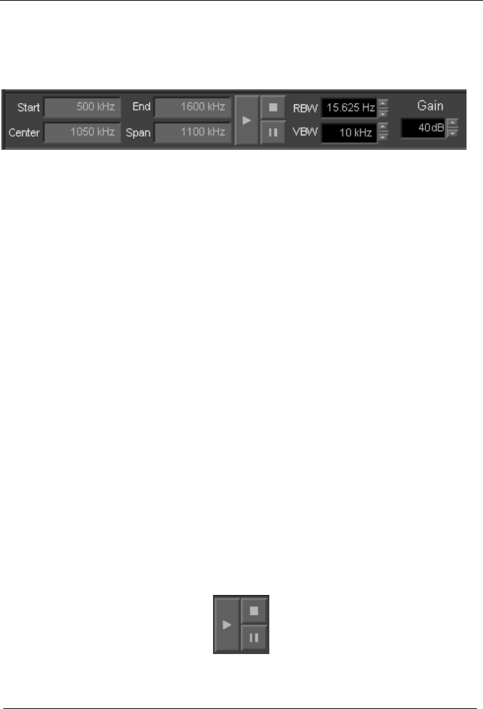
WiNRADiO G3XX VHF/UHF Receiver
To set up spectrum sweeping, enter the Start and End frequencies to specify
the start and end of the sweeping range, respectively. Alternatively, you may
enter the Center and Span frequencies.
Next select the RBW (Resolution Bandwidth), which determines how detailed
the spectrum will be (the lower the RBW, the finer the detail). The finest RBW
is 15.625 Hz. The RBW has a proportional effect on the spectrum sweeping
speed, i.e. the greater the RBW, the faster speed, but at the expense of detail.
The VBW (Video Bandwidth) is a low-pass filter which is applied to the
resulting “video” trace of the signal and makes it possible to smooth the trace.
The lower the VBW, the smoother the trace. This setting has the same effect
as the Video Filter in the demodulator panel.
The spectrum analyzer, when activated, disables the AGC. This is in order to
have a uniform gain for the entire scanning range – if the gain was changing
due to the AGC action, the spectrum trace would be distorted (stronger signals
would appear weaker, and weaker signals would appear stronger). The Gain
control (adjustable from 0 to 99 dB) is used to set the IF gain for the spectrum
analyzer.
Note that if the gain is set too high, the receiver may overload in the presence
of strong signals and the trace will be distorted around these signals. On the
other hand, if the gain is too low, some weak signal peaks may be missed.
The sweeping is controlled using a set of buttons similar to an audio recorder:
The Start button (with a triangle) starts sweeping. The Stop button (with a
square) stops sweeping, while the Pause button (with two vertical lines)
pauses it:
62

WiNRADiO G3XX User’s Manual
The button with a red round arrow selects continuous sweeping mode,
which means that the sweep will continue from the start frequency when the
end frequency is reached, and continue in this loop until manually stopped. If
this button is disengaged, the spectrum analyzer will be in a single shot
sweeping mode:
When the mouse cursor is positioned over the spectrum graph, a red cursor
will appear. Clicking anywhere on the spectrum graph tunes the receiver to the
corresponding frequency. You can also drag the mouse horizontally across the
spectrum and continuously tune the receiver.
The frequency corresponding to the cursor position, as well as the
corresponding signal level will be shown above the spectrum graph. In addition
to the frequency and level, minimum, maximum and their difference values are
also shown. These are values obtained throughout the entire time that the
spectrum analyzer is sweeping. Note that if the spectrum analyzer is in the
single-shot mode, the min and max values will be equal upon the termination
of the sweep.
Right-clicking on the spectrum graph will cause a stationary blue vertical line,
the “marker” to appear over the graph. The marker can be either dragged
using the mouse, or repositioned by simply right-clicking on a new location.
The marker can be made invisible by disengaging the Show Marker button:
The Show marker button gets activated automatically upon right-clicking on
the spectrum graph.
When the marker is activated, marker frequency and the associated trace
values will be displayed under the cursor values. If the marker delta mode is
activated using the Marker Delta Mode button, these values will become
differential with respect to values associated with the current position of the
cursor:
63
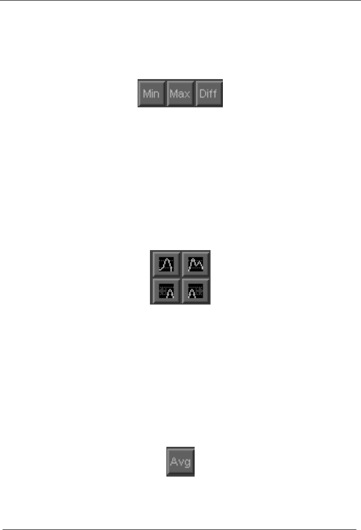
WiNRADiO G3XX VHF/UHF Receiver
The Min, Max and Diff buttons enable the display of minimum, maximum and
differential values when continuous sweeping is selected. (A scale for the
differential trace will be displayed on the right-hand side whenever the Diff
button is pressed.)
The differential trace is very useful when investigating activity on a given band.
The receiver can be left unattended in the continuous sweeping mode, and
any activity on the band will be clearly visible on the differential trace.
Note that it is also possible to save a spectrum graph and then load it later to
perform a new sweep to show differences from the old graph, to see what has
changed on the band in the meantime.
The G3XX Spectrum Analyzer also contains special function buttons to locate
peaks in the displayed frequency spectrum:
The Find Maximum Peak button (top left of the four) locates the maximum
peak of the entire spectrum and positions the marker over the peak. The Find
Next Peak (top right) find the next tallest peak. The two buttons below, Find
Peak Left and Find Peak Right, locate the next tallest peaks in the respective
direction.
The Averaging button enables trace averaging. With trace averaging
enabled, the displayed trace is not the actual currently swept trace, but rather
an average of the currently swept trace and the previous trace:
64
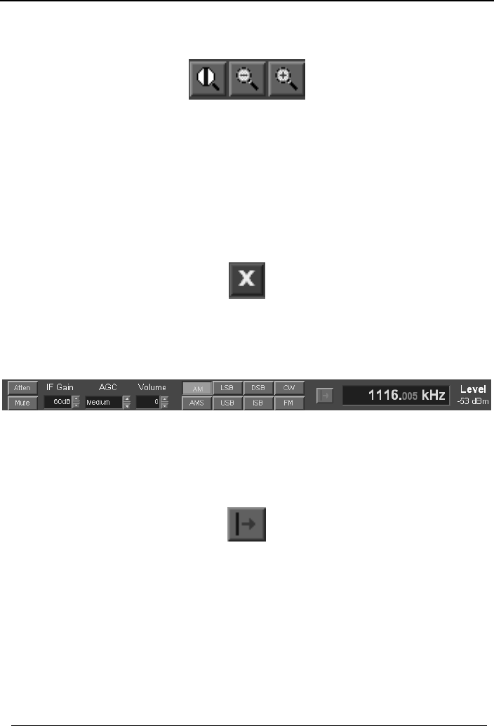
WiNRADiO G3XX User’s Manual
There are also three zoom-related buttons:
The first button centers the zooming action around the marker (if the marker
position has been set) - if this button is disabled then zooming will be done
with respect to the center of the screen. The next two buttons perform the
actual zooming in and out functions.
To hide the Spectrum Analyzer, use the yellow X button at bottom right:
The larger of the two versions of the spectrum scope contains basic controls of
the receiver, which are self-explanatory:
The only additional feature is the Tune to marker button. This is a momentary
button which tunes the receiver to the current marker frequency, if the marker
is enabled:
65

WiNRADiO G3XX VHF/UHF Receiver
66
Appendix A – Troubleshooting
Problem: The WiNRADiO application installed OK, but there is no sound
coming from the speaker.
Solution: Check if you see any noise appearing in the spectrum scope
in the demodulator panel (under the AM, AMS, etc., mode
selection buttons). When you tune to a station, you should be
able to see a peak on the real-time spectrum scope. If you
can’t see any peak, please make sure your antenna is
properly connected. If you can see a peak but there is no
sound coming from the speaker, please check the following:
• The Mute button in the demodulator panel is disengaged and the volume
is set to a medium level (say 15).
• SAGC is set to medium.
• The squelch is set below the current signal level, or disabled using the
Defeat (squelch defeat) button.
• The Attenuator is off, Preamp is on, and AGC is set to medium.
• With G3XXi receiver, the receiver audio output is connected either to an
amplified speaker (a standard PC multimedia speaker with stereo input
cable), or to the sound card Line input using the supplied cable. (If your
PC sound card does not have a Line input, you can use alternative inputs
such as Aux or Microphone.)
• If the receiver is connected directly to amplified speakers, make sure they
are turned on, and the volume is set to approximately one half. If you are
using the sound card for the audio output, check that the input to which the
receiver is connected to is not muted in the sound card control panel and
the volume is also set to approximately one half:
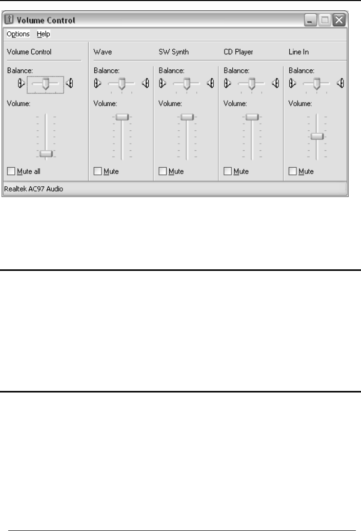
WiNRADiO G3XX User’s Manual
Note: If you have difficulties accessing the sound card control panels (for
example if there is no speaker icon), refer to Appendix B – Sound Card
Controls.
Problem: I can hear the audio and tune the receiver, but the sound is
distorted.
Solution: Check if the AGC is switched on (i.e. either the Slow, Med or
Fast buttons are pressed – usually the medium setting should
be used). Also set SAGC to Med. In the demodulator Setup,
adjust the SAGC reference level down.
Problem: The sound is OK in AM mode, but FM mode sounds distorted.
Solution: Ensure that the Audio filter in on, and set to Bandpass in the
demodulator Setup, with de-emphasis set to -6dB/oct. Also try
to reduce Audio gain under Demodulator settings.
67

WiNRADiO G3XX VHF/UHF Receiver
Problem: I can hear the audio and tune the receiver, but the volume is
too low, even if I adjust the volume control to maximum.
Solution: Presuming the volume is set to the maximum level (31) in the
demodulator panel, you can adjust the volume also in the
sound card control panel, or on the amplified speakers you
are using. Also, if SAGC function is turned off, turn it on by
clicking the Med button:
You can increase the volume when SAGC is on by adjusting
the AGC reference level under Setup (excessive level will
cause distortion). If you prefer to keep SAGC off, you can
increase the volume under Setup, by adjusting the Audio
gain level.
Problem: I can hear the audio and tune the receiver, but the spectrum
scope display is very sluggish, sometimes it even freezes.
Solution: Close all other simultaneously running programs to reduce the
burden on the CPU. This may indicate insufficient CPU
resources in your PC. Perhaps you have too many programs
running in the background?
Problem: I can hear the audio and tune the receiver, but the audio is
very noisy. The background noise level displayed on the
spectrum scope appears very high.
Solution: Make sure the Attenuator is switched off and the Preamp is
on. Check that your antenna is properly connected, the
connector is not loose and that the antenna cable is not
damaged. Does the noise floor drop significantly if you
disconnect the antenna? If so, then perhaps the antenna is
picking up too much ambient noise. Try to improve the
antenna, or move it further away from the PC. (For additional
noise-defeating measures see also Appendix C – Dealing
With Interference.)
68

WiNRADiO G3XX User’s Manual
69
Problem: Reception is obscured with a buzzing interference.
Solution: Check for the sources of interference in your surroundings: it
could be fluorescent lights, a lamp dimmer, or other household
appliances. Your PC (especially the monitor) could be the
culprit. Unless you are able to suppress the interference at
the source, the only solution is to install a better antenna,
preferably an outdoor one. Computer networks are especially
noisy and if your PC is connected to one, you will almost
certainly need an outdoor antenna. If the interference level
varies periodically with peaks about 30-100 kHz apart, the
most likely culprit is the monitor or the video card. Switch the
monitor off - if the interference disappears then the cause is
the monitor. Modern LCD monitors generate much lower
levels of interference than CRT ones. (See also Appendix C
– Dealing With Interference.)
Problem: I managed to drag the spectrum scope window down to the
point where the bottom is now obscured, so that I can't drag it
back (and the top is as high at the top of the screen as I could
go).
Solution: Windows allows you to resize any window up to the height of
the desktop. This problem can happen after resizing almost
any resizeable windows.
You can resize or move the taskbar (just like any other
window) to reveal the bottom of G3XX panel. Make sure that
Lock the Taskbar is not checked in the pop-up menu (right-
click on an empty space on the taskbar). If the taskbar is
locked, you can't resize or move it. If you prefer to move the
taskbar to the left side of the desktop, just hold the mouse on
the empty space and drag it.

WiNRADiO G3XX VHF/UHF Receiver
70
Another way to solve this problem is to close the G3XX
application and manually edit the wrG3XXni file in the Windows
directory. For example, you will see values similar to these:
[Scope-03E27014]
Visible=1
Height=300
where 03E27014 is the serial number of your receiver. Your
'Height' value is probably greater, but you should change it to a
reasonable value (about 200).

WiNRADiO G3XX User’s Manual
71
Appendix B – Sound Card Controls
Sound card control panels and their settings can be somewhat confusing.
They are also rather inconsistent from one version of Windows to another.
The G3XXe receiver requires that the sound card Wave input is unmuted. The
volume can be then adjusted using the Wave slider and the master Volume
Control.
The G3XXi receiver does not require a sound card as the output is already a
converted analog Line Output. You can connect this directly to standard
amplified multimedia speakers or an external amplifier of your choice. You can
also connect it to a sound card.
If you wish to connect your G3XXi receiver to a sound card, you can simply
use the supplied audio cable and connect it to the Line input (alternatively to
Microphone input, if the Line input is not available). The output volume is
controlled by the Playback volume control of the sound card.
Typically, you would access the Playback volume control panel by clicking the
speaker icon in the Windows Task Bar.
If the speaker icon is missing, an alternate way to accessing the Playback
controls is via the Windows Control Panel. Here you can also enable or
disable the speaker icon.
The table on the following page shows how to enable or disable the speaker
icon, and how to get to the playback controls from within the Windows control
panel. The methods vary depending on the version of Windows you are using.
Did you know?
The ubiquitous PC sound card was invented in Singapore by Sim Wong Hoo,
engineer and entrepreneur, who founded the Creative Technology company in
1981. His first product, an Apple computer clone, did not take off. However, his
second product, the PC sound card, hit its target well: More than 120 million
sound cards have been shipped by Creative Technology, mostly under the
Sound Blaster brand.

WiNRADiO G3XX VHF/UHF Receiver
Windows Enable “speaker” icon Recording/playback volume controls
98 Control Panel |
Multimedia
Audio-tab
Checkbox: “Show
volume control on the
taskbar”
Control Panel | Multimedia
Audio-tab
Sound Playback: Click on button
ME Control Panel |
Sounds and
Multimedia
Sounds-tab
Checkbox: “Show
volume control on the
taskbar”
Control Panel | Sounds and
Multimedia Audio-tab
Sound Playback Æ Volume button
2000 Control Panel |
Sounds and
Multimedia
Sounds-tab
Checkbox: “Show
volume control on the
taskbar”
Control Panel | Sounds and
Multimedia Audio-tab
Sound Playback Æ Volume button
XP Control Panel |
Sounds and
Multimedia |
Sounds-tab
Checkbox: “Place
volume icon in the
taskbar”
Control Panel | Sounds and
Multimedia Audio-tab
Sound Playback Æ Volume button
72

WiNRADiO G3XX User’s Manual
73
Appendix C – Dealing with Interference
Electromagnetic Interference (EMI) is what prevents us from receiving a
clear signal, even when the receiver should be sensitive enough to receive it.
There are many types of interference you can experience with radio receivers,
emanating from both natural and man-made sources.
Natural interference is produced by atmospheric phenomena such as storms
and sun activity.
Not so surprisingly, man-made interference is often worse. Sources include
electric motors, power lines, passing cars, electrical welding equipment,
fluorescent lights, fax machines, computer networks, etc. Receiving antennas
should always be as far away from sources of electromagnetic interference as
possible.
One significant source of man-made electromagnetic interference is the
personal computer, and the video monitor in particular. Since the WiNRADiO
G3XX receiver requires a personal computer to operate, this creates a
potential paradox. The WiNRADiO receiver itself is designed to be
substantially immune to PC interference. However, any receiver needs to be
connected to an antenna, and antennas can’t discriminate between useful
signals and interference. The interference from your PC can either radiate
directly to the antenna, or it can be conducted to it along the outer conductor of
the lead-in cable. Even in professional radio receiving stations, a lot of care
and effort is always needed, if this type of self-interference is to be avoided.
Some computers are worse than others in terms of generated electromagnetic
interference. The worst culprits are usually video monitors, which radiate radio
frequencies at multiples of horizontal deflection frequencies. These
frequencies range from about 30 to 100 kHz, and you can sometimes hear
their harmonics right across the entire shortwave band. If you find strong
signals sounding somewhat like a tractor engine, spaced between
approximately 30 and 100 kHz apart (on modern hi-resolution monitors, the
typical frequency is around 94 kHz), your monitor is most likely the cause.

WiNRADiO G3XX VHF/UHF Receiver
74
To check this, tune to one of the interfering signals, then switch off the monitor
and see if the signal disappears. If the interference still exists you could
continue using the WiNRADiO receiver, and live with the fact that some useful
frequencies will be obscured by your monitor’s interference, or you can replace
your monitor with a ‘quieter’ one (modern LCD displays are far quieter than old
CRT monitors), or you can try to relocate your antenna further away from your
computer.
A good remedy to try is to wind five to ten turns of the antenna lead-in cable
through a large ferrite core (the doughnut shaped toroid type), near the PC
end of the cable. This suppresses common-mode interference, which is a
typical but curable problem with PC-controlled receivers.
Another type of interference which you may encounter is intermodulation
interference. This is usually caused by strong local stations, whose
frequencies combine to create ‘ghost’ signals on frequencies which are
arithmetic combinations of the stations’ frequencies. These ‘ghost’ signals can
sometimes coincide with useful frequencies, rendering them partially or
completely unusable. They will usually disappear when you switch on the
Attenuator in the receiver control panel. You may also try shortening the
antenna.
If you live very close to a strong local transmitter, these measures may be
insufficient. In such case, you should be able to eliminate intermodulation by
fitting a special filter to your antenna, to reduce the level of the signals causing
the interference. The design and application of such filters falls beyond the
scope of this user’s guide. However, broadcast frequency filters and tunable
preselectors are standard items and can be obtained from good radio
equipment suppliers.
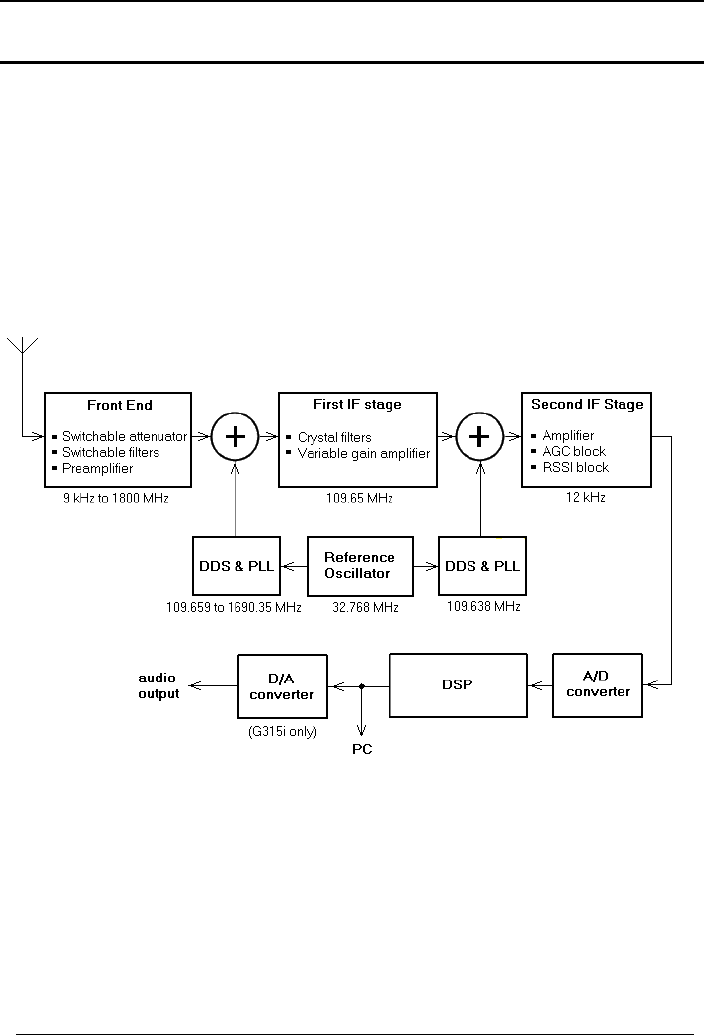
WiNRADiO G3XX User’s Manual
Appendix D – Inside WR-G3XX Hardware
Technically minded users may like to explore the WiNRADiO G3XX Receiver
and experiment with some of the innovative concepts of this Software
Defined Radio.
The WiNRADiO G3XX Receiver is one of the first commercially available
Software Defined Radios, where the Demodulator function is fully performed in
software.
The receiver hardware contains the following functional blocks:
The incoming signal from the antenna (in the 9 kHz to 1800 MHz range, is
filtered and amplified, then fed into a mixer. Here it is mixed with the first LO
(local oscillator), which is performed by a DDS (Direct Digital Synthesizer),
with a PLL (Phase Locked Loop). The resulting 109.65 MHz intermediate
frequency is filtered using two 4-pole 109.65 MHz crystal filters with an IF
bandwidth of 15 kHz, and then amplified.
75

WiNRADiO G3XX VHF/UHF Receiver
76
The second mixer again uses a DDS with a PLL to mix the 109.65 MHz signal
down to the last intermediate frequency, which is 12 kHz (the last IF
frequencies may be selected within a range of 12 to 22 kHz, to suit various
special applications).
The receiver’s internal reference frequency for both DDS circuits is
16.384 MHz, which is derived from a precise 32.768 MHz oscillator.
The 12 kHz centered output of the second IF stage is fed to a 16-bit A/D
converter sampling at 64 kHz. This digitized signal is processed by a DSP
which performs digital filtering (responsible for the variable IF bandwidth) and
demodulation. Additional digital signal processing (for example FFT functions
related to the real-time spectrum scope and selective S-meter) is performed on
the host PC.
The AGC is performed in the first IF stage, based on the level of the last IF
output. The AGC action is delayed until the dynamic range of the first IF stage
is fully utilized – this is in order to prevent desensitization of the receiver in the
presence of neighbouring strong signals, falling within the 15 kHz IF
bandwidth. The resulting variation in audio output is then compensated in
software, using the Software AGC facility of the demodulator.
Note: Such a mixed arrangement, where the critical analog-to-digital sampling
and processing are done by the on-board DSP while the rest is performed by
the PC (rather than all processing being done on the PC), has the advantage
of providing consistently high performance by eliminating performance
variations caused by poor quality or incorrectly set up PC sound cards. A
higher quality analog-to-digital converter used in the G3XX receiver makes
also a higher sampling rate possible than is available on a standard PC sound
card, which results in a further improved performance. With the time-critical
demodulation code running on the DSP, this also makes it possible for a single
PC to support several receivers running simultaneously without burdening the
CPU resources.
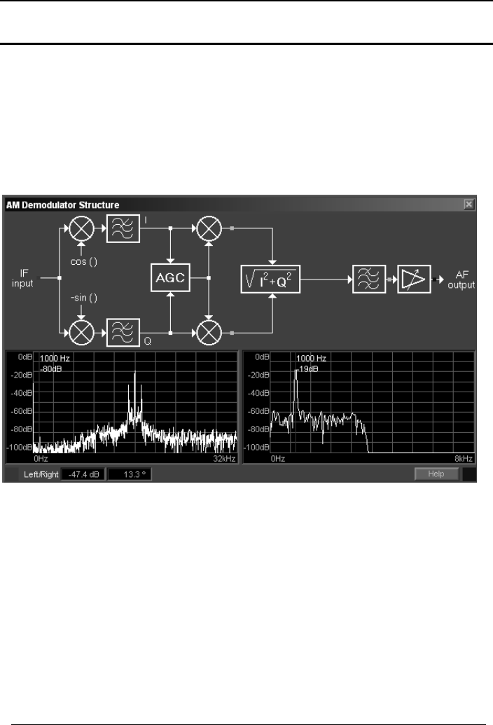
WiNRADiO G3XX User’s Manual
Appendix E – Inside WR-G3XX Demodulator
The internal structure of the G3XX demodulator is easily accessible by
pressing the Study button in the demodulator panel.
The G3XX Demodulator relies on a general quadrature representation of the
incoming modulated signals. Such signals can always be considered as the
sum of two amplitude-modulated carriers having a 90 degree offset, usually
referred to as I & Q.
AM Demodulator Structure
The demodulator structure windows include two spectrum analyzers making it
possible to view signal spectra in real-time. Each analyzer can be associated
with any of the test points shown as green dots in the diagram. To connect
the left spectrum analyzer to a particular test point, left-click on the green test
point. Its color will change to red. Right-clicking on a dot will connect it to the
right analyzer, and the color will change to blue. If both displays are connected
to the same test point, the point color will turn magenta.
77
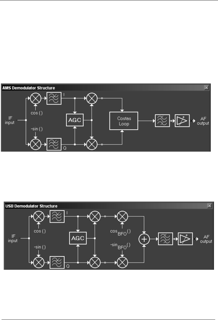
WiNRADiO G3XX VHF/UHF Receiver
Within the displayed spectra, a red color frequency cursor can be manually
dragged, using the left mouse button, over a particular spectral component.
The two Vector Voltmeter displays labelled Left/Right indicate the relative
amplitude and phase difference between the two spectral components at the
cursor frequency.
For synchronous demodulation of amplitude modulated signals (the AMS
mode) without carrier or with a fluctuating one, the G3XX demodulator uses a
PLL carrier recovery technique based on the Costas loop:
Synchronous AM Demodulator Structure
The LSB and USB demodulators have basically the same topology. ISB can
be thought of as a combination of LSB and USB, where each of the sound
card channels is used for one of the independent side bands.
USB Demodulator Structure
78
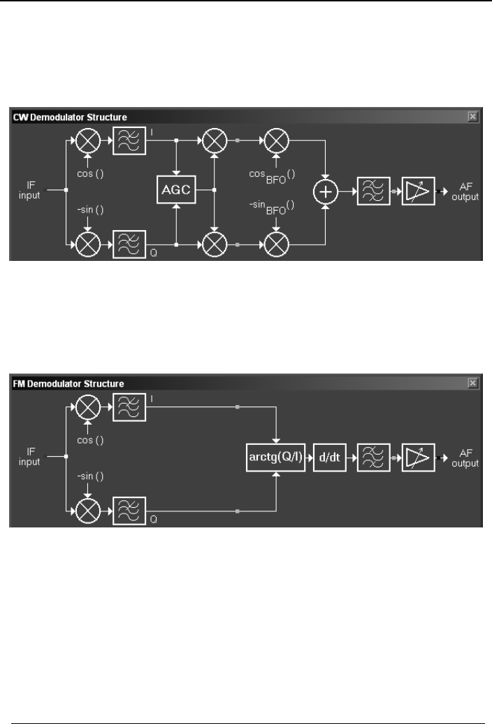
WiNRADiO G3XX User’s Manual
The CW received signals are first down-converted to zero Hz, and then, after
additional channel filtering, up-converted to a convenient audio frequency. This
frequency (a digital BFO) is user-adjustable, by changing the value of the CW
tone frequency parameter in the demodulator setup.
CW Demodulator Structure
Finally, the frequency demodulator performs a time derivative function on
arctangent of Q over I, to arrive at amplitude-independent frequency
demodulation of the input signal:
79

WiNRADiO G3XX VHF/UHF Receiver
80
Appendix F – Developer Support
WiNRADiO has always extensively supported third-party software
development efforts with all our receivers, and the WiNRADiO G3XX receiver
is no exception. We provide technical details for developers to be able to
develop the following:
• Third-party applications controlling the WiNRADiO G3XX receiver.
• We do this by providing API information making it possible to access the
receiver hardware from third party software. (See
http://www.winradio.com/home/developer.htm).
• Plug-ins to provide enhanced functionality. For this, we have developed a
special interfacing standard called XRS (eXtensible Radio Specification).
All our receivers conform to this standard, and many plug-ins are already
available for various applications (see http://xrs.winradio.com).
• New types of demodulators. The G3XX demodulators in fact represent a
special type of XRS plug-in. Detailed information is also available at
http://xrs.winradio.com).
• Support under alternative operating systems. See for example
http://www.linradio.com.
• Support under Radio Basic, an easy to use specialized programming
language for radio receivers. See http://www.rbasic.com.
Have you registered yet? WiNRADiO provides regular upgrades to our
application software. Use our on-line registration form on
www.winradio.com/register to take advantage of this free service.

WiNRADiO G3XX User’s Manual
81
Appendix G – Wide-band FM Option
“WFM” option makes it possible to receive wide-band modulated signals
(“broadcast FM”) on the G3XX receivers. On the standard G3XX receiver, the
wide-band FM capability is not included, because it is not possible to provide
this within the constraints of the 15 kHz instantaneous bandwidth of the
digitized IF signal and the DSP software processing power.
The WFM option is in fact a self-contained “hardware-defined” receiver. The
user can receive wide FM broadcasts, but cannot see the entire 230 kHz
bandwidth in real time. Instead, the real-time spectrum panel shows
demodulated audio spectrum. It is also not possible to perform IF recording,
but it is of course possible to make audio recording.

WiNRADiO G3XX VHF/UHF Receiver
82
Appendix H – Frequency Calibration
The G3XX receiver series features an excellent frequency accuracy and
stability for a receiver of its class. It is however possible to improve this
accuracy yet further, by individual calibration.
The receiver calibration is accomplished by inserting a reference frequency
parameter in the wrG3XX.ini file which resides in the Windows directory. The
reference frequency parameter consists of two lines of the following format:
[ClockCalibration]
receiver_serial_number=reference_frequency
The receiver serial number can be obtained for example from the About box in
the G3XX application. The reference frequency is the actual frequency of the
internal reference oscillator in Hz. This is normally 16.384 MHz, i.e. 16384000
Hz.
Each receiver is factory calibrated, so a fundamental correction to the nominal
16.384 MHz reference frequency already exists and is stored in the receiver's
internal memory. This correction can be overridden by the new parameter in
the wrG3XX.ini file. To determine the true offset from a perfect tuning, firstly
use 16384000 (i.e. the nominal reference frequency in Hz) as the
reference_frequency parameter. Say your receiver serial number is
02L27011:
[ClockCalibration]
02L27011=16384000
Save the wrG3XX.ini file with this value, then start the G3XX application. The
frequency error will be now much worse because the new parameter overrides
the original factory calibration. Then tune the receiver to a known frequency
standard. A high-accuracy signal generator can be used, or one of the WWV
Time and Frequency Standard stations. Observe the peak with the spectrum
scope and listen to the beat frequency in the CW mode with a minimum IF
bandwidth. Then note down the frequency difference. (For example, -152 Hz
at 10 MHz).

WiNRADiO G3XX User’s Manual
83
Then scale the frequency difference to 16.384 MHz. For example, if the
frequency difference is -152 Hz at 10 MHz, it will be -249 Hz at the
16.384 MHz reference frequency.
To arrive at the corrected reference frequency, subtract the frequency
difference from 16384000. In our example, 16384000-(-249)=16384249. The
entire reference frequency parameter in the wrG3XX.ini file will be then as
follows:
[ClockCalibration]
02L27011=16384249
Save the wrG3XX.ini file, then restart the G3XX application and observe the
difference.
To return to the original factory frequency calibration, simply delete the
inserted two lines in the wrG3XX.ini file. You can also delete the entire file
(which will however result in losing all current receiver settings and return to
factory defaults for all of them).
Did you know?
The WWV Time and Frequency Standard station which broadcasts on 2.5, 5,
10, 15 and 20 MHz, has a long history that dates back to the very beginning of
radio broadcasting. The call letters WWV were assigned to the US National
Institute of Standards and Technology (then called the National Bureau of
Standards) in October 1919. By December 1922, it was decided that the
station’s purpose would be the transmission of standard frequency signals.
The accuracy of the transmitted frequency was quoted as being better than 0.3
per cent. Nowadays the station frequency is controlled within one part in 1013,
which represents frequency accuracy thirty billion times better.

WiNRADiO G3XX VHF/UHF Receiver
84
Appendix I – S-meter Calibration
The G3XX receiver series features a uniquely accurate and powerful S-meter.
However, it is possible to improve this accuracy yet further, by individual
calibration.
The receiver S-meter calibration is done using a special S-meter Calibrator
application, which can be downloaded from WiNRADiO Web page
www.winradio.com/home/calibrator.htm.
The S-meter Calibrator alters the factory-supplied default data in the receiver
calibration file wrG3XX.cal which resides in the receiver application folder (i.e.
typically C:/Program files/WiNRADiO/G3XX).
The S-meter Calibrator requires the use of a precisely calibrated synthesized
signal generator to generate calibration levels in the frequency range of
interest. It possible to create calibration tables for as many frequency points as
required, and interpolate between these tables to arrive at absolute calibration
values for any arbitrary frequency the receiver is tuned to.
The S-meter Calibrator includes special commands to create, edit and
manipulate calibration tables, interpolate between individual calibration points
within a particular table as well as between entire tables, view calibration
graphs for individual frequencies, and other useful facilities.
The S-meter Calibrator is provided as an “as is” complimentary tool for
WiNRADiO receiver users. The calibration procedures should not be
attempted by persons without a deeper understanding of the underlying
concepts, as WiNRADiO can only provide a limited technical support for this
application, and can accept no responsibility for any difficulties arising from its
use.
To restore the original factory calibration, simply delete the wrG3XX.cal file
and reinstall the G3XX application.

WiNRADiO G3XX User’s Manual
85
Appendix J – USB Interface Diagnostics
The flashing pattern of the blue LED on the external G3XXe model has a
diagnostics meaning. Normally, when the receiver is powered up and the
application running, the blue LED should flash in a dih-dah pattern (i.e. a short
flash followed by a long one).
A complete list of the flashing patterns and their meaning is as follows:
Pattern Description Mode
Off No power
- Long flash, equal gap No connection to
computer
.. Two short flashes USB connected, driver
installed, application
running, radio off
.- One short flash,
followed by a long one USB connected, driver
installed, application
running, radio on
..- Two short flashes
followed by a long one USB connected, but
driver not installed
... Three short flashes USB connected, driver
installed, application not
running

WiNRADiO G3XX VHF/UHF Receiver
86