Roche Diagnostics COBAS80 Inductive Tag Reader User Manual Delivery Specification COBAS Reader 8000
Roche Diagnostics GmbH Inductive Tag Reader Delivery Specification COBAS Reader 8000
Users Manual

Delivery_Specification_COBAS_Reader_Roche_v1.1.1.odt 1 / 30
Delivery specification
COBAS-Reader 8000
Revision: 1.1.1

Delivery_Specification_COBAS_Reader_Roche_v1.1.1.odt 2 / 30
Document approval signatures
Responsible for definition and writing of specification:
Company Name Date Signature
Author TagStar Systems Michael Kober 17.02.2009
Reviewer maxsol Max Schneider
Reviewer etifix Heinz-Jörg Schröder
Reviewer Roche Helmut Jering
Approval and release of specification:
Company Name Date Signature
Approval RD S. Rosenblatt
Delivery_Specification_COBAS_Reader_Roche_v1.1.1.odt 3 / 30

Delivery_Specification_COBAS_Reader_Roche_v1.1.1.odt 4 / 30

Contents
1 General description......................................................................................................................................7
1.1 Supported RFID chips.........................................................................................................................................7
1.2 Functional description.........................................................................................................................................7
1.3 Model, Manufacturer..........................................................................................................................................8
1.4 Labelling..............................................................................................................................................................8
2 Applied standards and regulations............................................................................................................11
3 Specification...............................................................................................................................................12
3.1 Power supply.....................................................................................................................................................12
3.2 RFID data..........................................................................................................................................................13
3.3 Optical sensors..................................................................................................................................................15
3.4 Environmental conditions.................................................................................................................................16
3.5 Dimensions........................................................................................................................................................18
3.6 Dimensions of reader housing..........................................................................................................................18
3.7 Channel positions..............................................................................................................................................20
3.8 Connector..........................................................................................................................................................21
3.9 Serial interface parameters................................................................................................................................21
3.10 Host communication protocol.........................................................................................................................22
3.11 Life time..........................................................................................................................................................22
4 Packaging....................................................................................................................................................22
5 Embargoed countries.................................................................................................................................23
6 Installation notes........................................................................................................................................23
6.1 Recommended software algorithm for cassette position detection..................................................................24
7 Possible interactions between the COBAS-Reader 8000 and the host system......................................25
8 Product warranty.......................................................................................................................................26
9 List of appendixes.......................................................................................................................................27
10 Document revisions..................................................................................................................................28
Delivery_Specification_COBAS_Reader_Roche_v1.1.1.odt 5 / 30

Delivery_Specification_COBAS_Reader_Roche_v1.1.1.odt 6 / 30
1 General description
The COBAS-Reader 8000 is a customer specific adopted RFID reader based on TagStar's TS1415 reader
technology. It is designed for the use in a Roche / Hitachi C701/702 system.
1.1 Supported RFID chips
Following ISO 15693-3 compatible chips are supported by the COBAS-Reader 8000 RFID reader.
Due to the project definition the COBAS reader supports the following RFID chip:
●NXP I-Code SLI, the following documents are attached:
I-Code SLI SL2 ICS20, Smart Label IC, Short Form Specification, April 2002 (Appendix 1)
I-Code SLI SL2 ICS20, Smart Label IC, Functional Specification, January 2003 (Appendix 2)
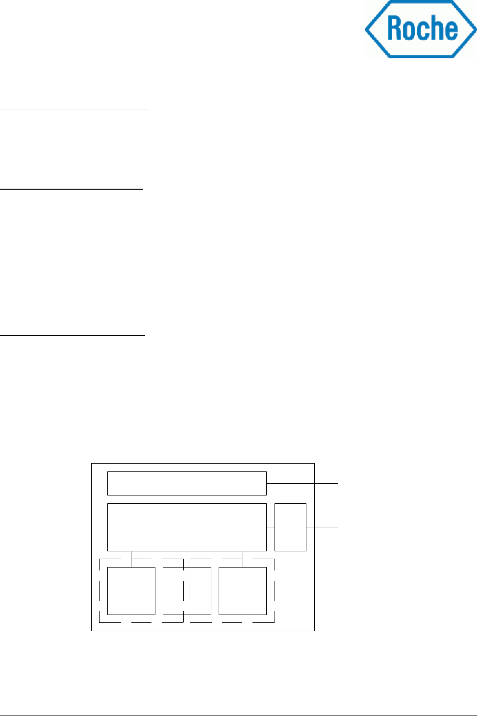
1.2 Functional description
The COBAS-Reader 8000 has a two channel detection system consisting of a RFID antenna and two optical
sensors each. The optical sensors are used to detect the rotational orientation of a cassette placed below the
reader unit. Therefore the cassettes are labelled with a black/white coloured RFID label. At the detection
process the RFID reader reads the data of the transponder which is inserted into the RFID label. To control
the cassette orientation both optical sensors measure the reflected light, which indicates the black and white
label area. Depending on the reflection value the host system could decide if the cassette is inserted in the
correct orientation or turned at 180°.
Delivery_Specification_COBAS_Reader_Roche_v1.1.1.odt 7 / 30
Drawing 1: Block diagram of COBAS RFID reader
Optical
Sensors
CH0
CH1
CH2
CH3
RFID
Channel 0
RFID
Channel 1
µC
Power regulator
RS232
driver
1.3 Model, Manufacturer
The COBAS-Reader 8000 can be ordered at etifix at the following order code:
COBAS-Reader 8000
The reader electronic unit consists of a two channel RFID reader main board, with two external detection
units. These detection units carry an adopted RFID antenna and two optical sensors for the position detection
of labelled cassettes. The electronic unit is assembled into a housing provided by etifix.
The whole production of the COBAS-Reader 8000 unit will be done under the responsibility of etifix and a
subcontractor which are ISO 9001:2000 certified. The subcontractor is qualified and trained to meet the
special requirements of RFID reader production. (Appendix 12, 13)
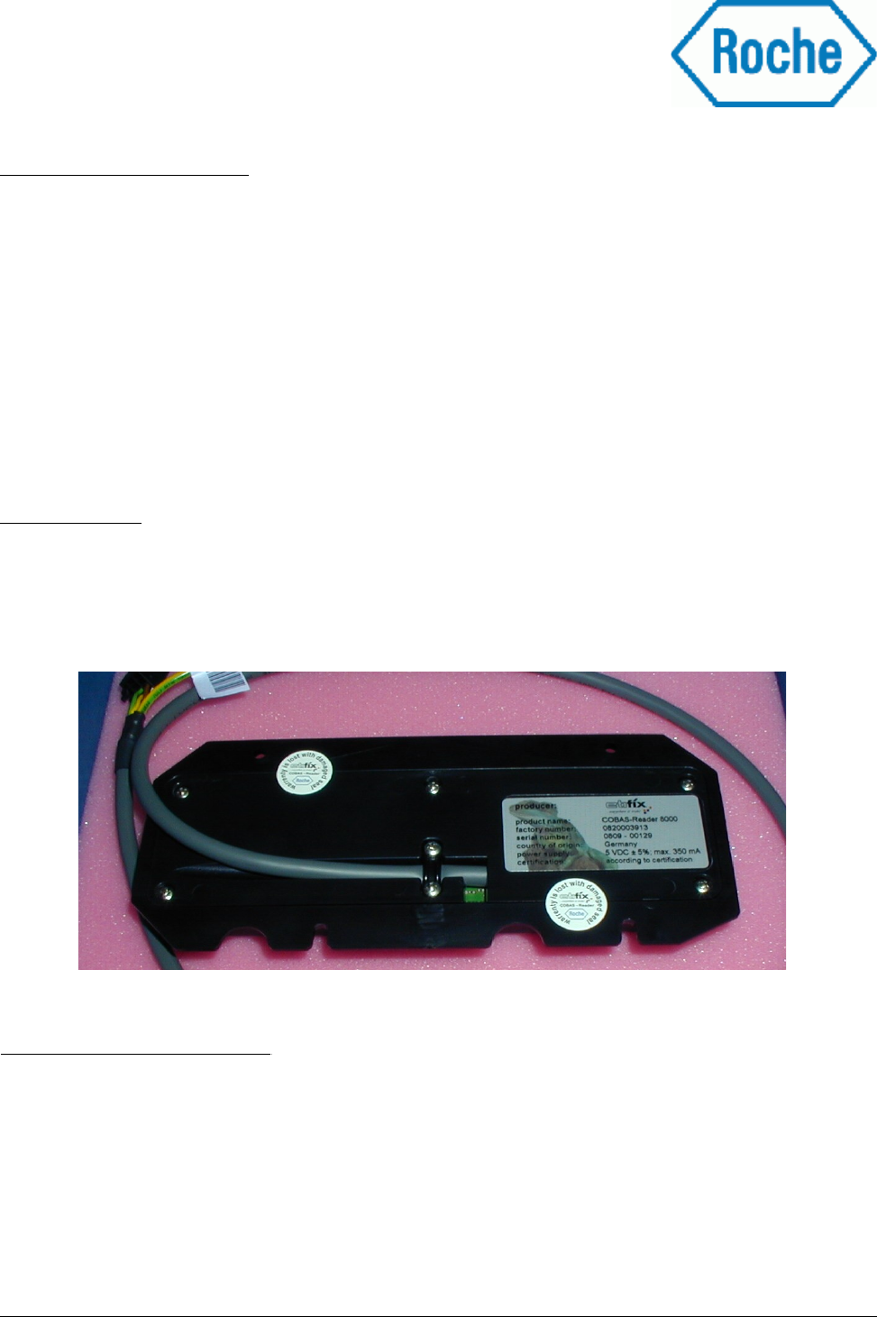
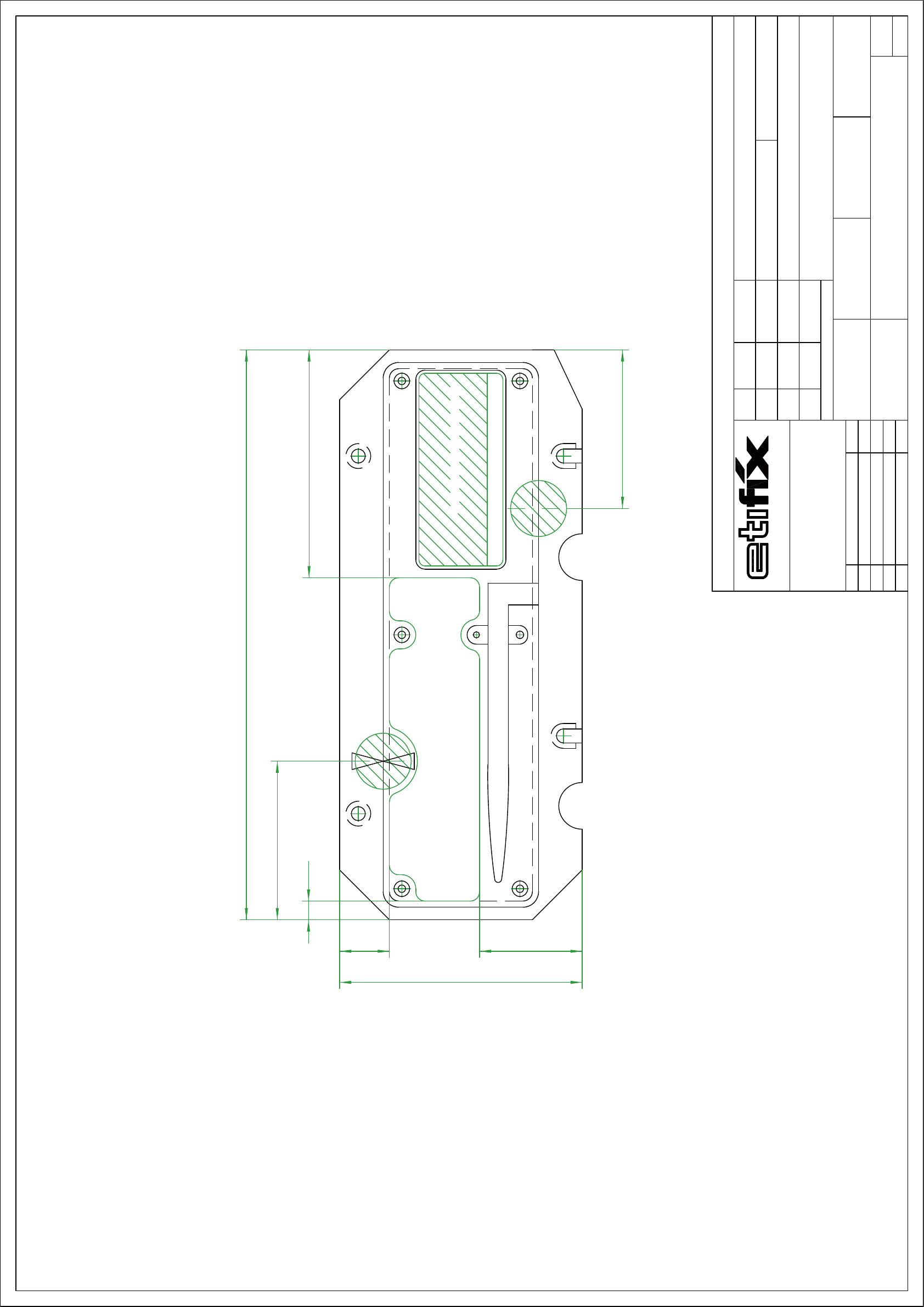
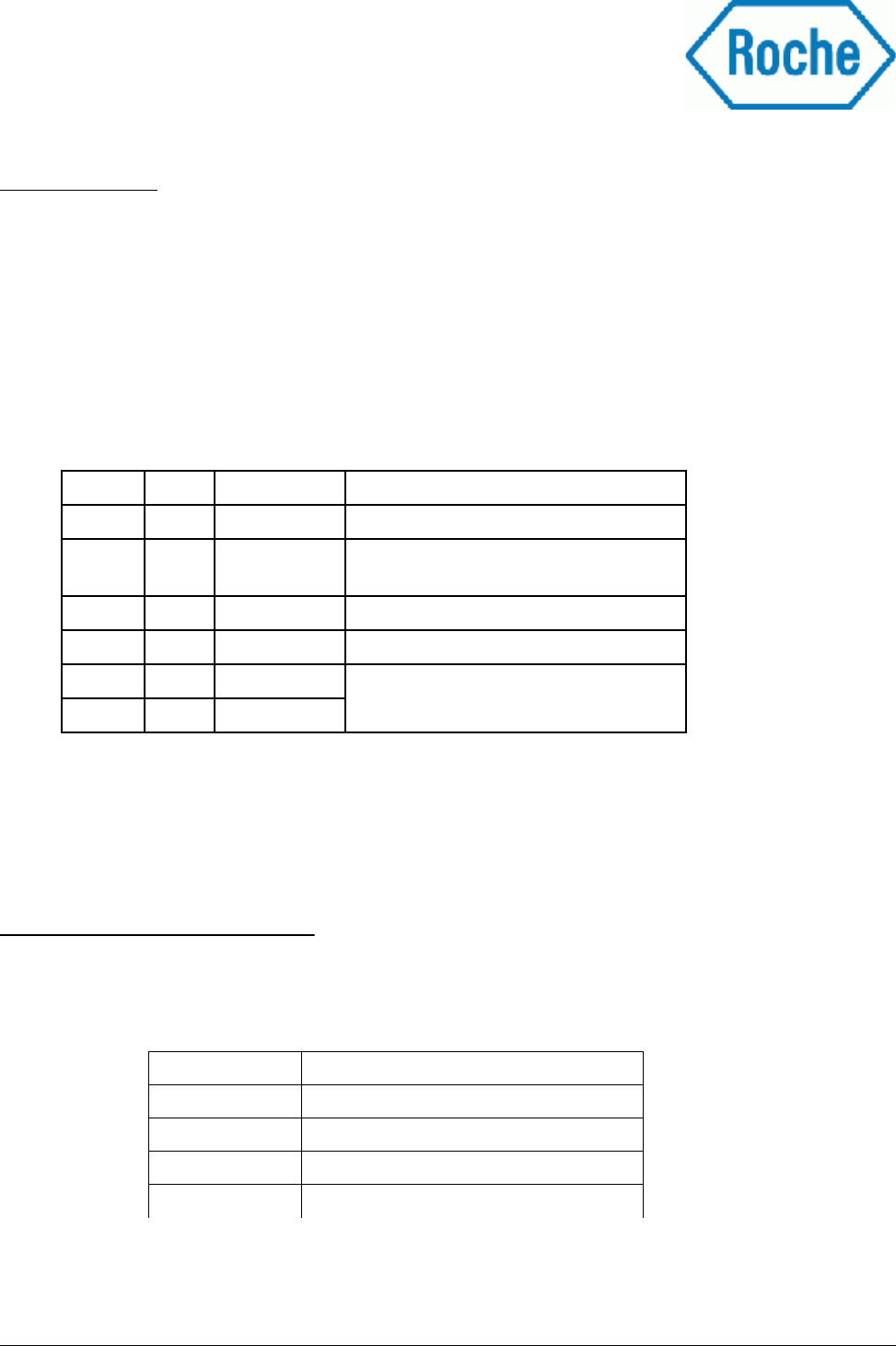
1.4 Labelling
Each COBAS-Reader 8000 is labelled with different identification and security labels. The following picture
shows the position of each label:
Position of labels on cassette:
The position of all labels on the cassette are shown on etifix drawing no. 7-50-1-1-2-1
Delivery_Specification_COBAS_Reader_Roche_v1.1.1.odt 8 / 30
Picture 1: Labelling of COBAS RFID reader
position of labels on the top side of the RFID reader
identication plate
maximium size for
certication labels
to place certication symbols
78
183,27
36 ±3 19 ±3
76 ±3
9±3
51
51
alle Oberächen ohne
Rauhtiefenangabe
gemittelte Rz min. 2,5
Teile ohne Form- und
Lagetoleranzenangaben
nach DIN 7184 T1
Achtung:
bei eingepaBter Zeichnung
auf eine DIN A... Seite
dürfen die MaBstabsangaben
nicht berücksichtigt werden
Maße ohne
Toleranzangabe
nach DIN 7168 f
D-72661 Grafenberg
Riedericher StraBe 68
1
1
Werksto
Name
Änderungen nur bei gleichzeitiger Berichtigung im CAD-System zulässig.
CAD Zeichnung
Benennung
Typ
Bl.
Blatt
Zeichnungs-Nr.
verwendet in Zeichnung Nr.
Norm
Gepr.
Bearb.
Zust. Änderung Datum Name
Datum
MaBstab
Mat.-Nr.:
7-50-1-1-2-1
RFID - Gehäuse COBAS 8000
10.11.08 D. Wurster 1:1 eingepasst
>
Diese Zeichnung ist unser Eigentum und darf ohne
unsere Zustimmung weder vervielfÌltigt noch an
Dritte herausgegeben werden.
Wir behalten uns alle Rechte für den Fall der
Schutzerteilung vor.
etix GmbH; D-72661 Grafenberg
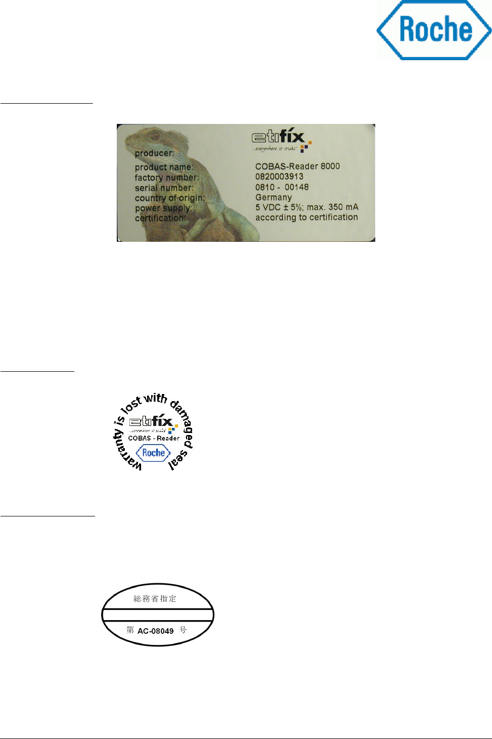
Identification label
Example of a label
The factory number is defined by etifix.
The serial number has the following syntax: JJMM-xxxx
JJ: Year of production
MM: Month of production
xxxx: Serial number of the reader, continuously increased
Security labels
Certification labels
Depending on national rules extra certification labels are applied on top of the reader housing.
Sample of a label:
Delivery_Specification_COBAS_Reader_Roche_v1.1.1.odt 10 / 30

2 Applied standards and regulations
The COBAS-Reader 8000 is conformal to the following radio regulations and standards:
●Europe (CE): EN 300 330-1 V1.3.1 (2001-06), EN 300 330-2 V1.3.1 (2006-04), ETSI EN 301 489-1
V1.6.1 (2005-09), ETSI EN 301 489-3 V1.4.1 (2002-08), EN 60950-1:2006, EN 50364:2001
●US: FCC Code of Federal Regulations, CFR 47, Part 15, Sections 15.205, 15.207, 15.215, 15.225
●Canada: Industry Canada Radio Standards Specifications
RSS-Gen Issue 2, Section 7.2.2, RSS-210 Issue 7, Sections 2.2, 2.6, A2.6 (Category I Equipment)
●Japan: ARIB standard T82 V1.1
The COBAS-Reader 8000 will be compliant to the upper mentioned standards.
For the in appendix “Country list for registration RFID readers 0-series and series for c701/702” (see
Appendix 3) listed countries a compliance certification will be applied for. Therefore additional standards
will be applicable, but are not listed under this chapter. The compliance measurement and appliance will be
done by CETEOM ordered by etifix.
Additional applicable standards:
●compliant to the RoHS regulations (Appendix 4)
●relevant components of the COBAS-Reader 8000 are UL recognized (Appendix 5)
Compliance certifications for national regulations are in progress of application and are not appended to the
document.
Delivery_Specification_COBAS_Reader_Roche_v1.1.1.odt 11 / 30
Warning: Any changes or modifications not expressly approved by the party responsible for compliance could
void the user's authority to operate the equipment.
3 Specification
The following reader parameters refer to the below shown coordinate system:
3.1 Power supply
Attention: Supply voltages higher than 5,5 V might permanently damage the circuitry of the
COBAS-Reader 8000 and have to be avoided.
The COBAS-Reader 8000 has no internal fuses or any inrush current limitation. It is recommended to
integrate an appropriate protection circuit into the power supply line to protect the reader and surrounding
hardware against damage in case of failure or over voltage. A suppressor diode is integrated into the power
supply circuitry. Specific data of the suppressor diode see appendix “1.5SMC6.8AT3-D” (Appendix 6).
The circuitry is operates with an internally stabilized voltage for optimum and stable operation.
Behaviour of the COBAS-Reader 8000 at different supply voltages see at Appendix 7.
Delivery_Specification_COBAS_Reader_Roche_v1.1.1.odt 12 / 30
Drawing 2: Coordinate system for measurement values
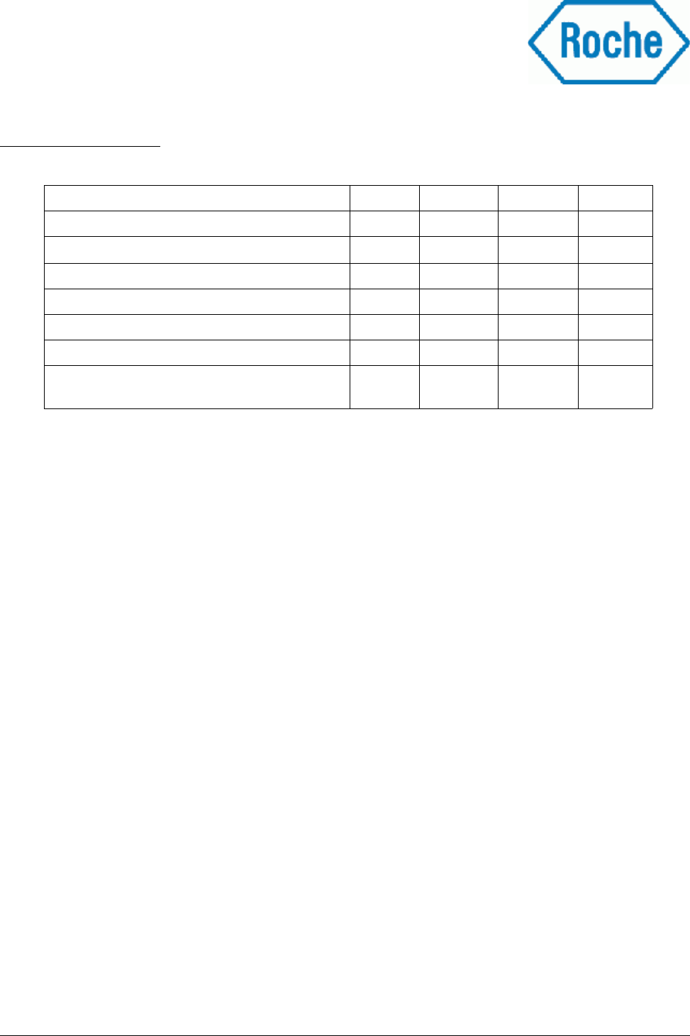
Value Symbol Min Max Unit
Supply voltage (at external connector) V 4,75 5,25 VDC
Max. ripple on supply voltage VSS 150 mVPP
Current consumption, standby 1) I standby 70 mA
Max. current consumption 2) I max 350 mA
Reader reset threshold voltage VThres 4,60 4,70 VDC
Table 1: Power supply ratings
1). .Measurement conditions: V = 5V, both RF channels switched off, all 4 LED's of the optical sensors are
switched off
2). .Measurement conditions: V = 5V, both RF channels switched on, all 4 LED's of the optical sensors
switched on
XY
Z
3.2 RFID data
Delivery_Specification_COBAS_Reader_Roche_v1.1.1.odt 13 / 30
Value Symbol Min Max Unit
RFID Frequency (typical) 13,56 MHz
Modulation degree according to ISO 15693 100% %
Data transfer rate Tag <–> Reader according to
ISO 15693
Data coding 1 out of 4
26,48 kBit/sec
RFID Output power @ 50 Ω termination PHF 70 90 mW
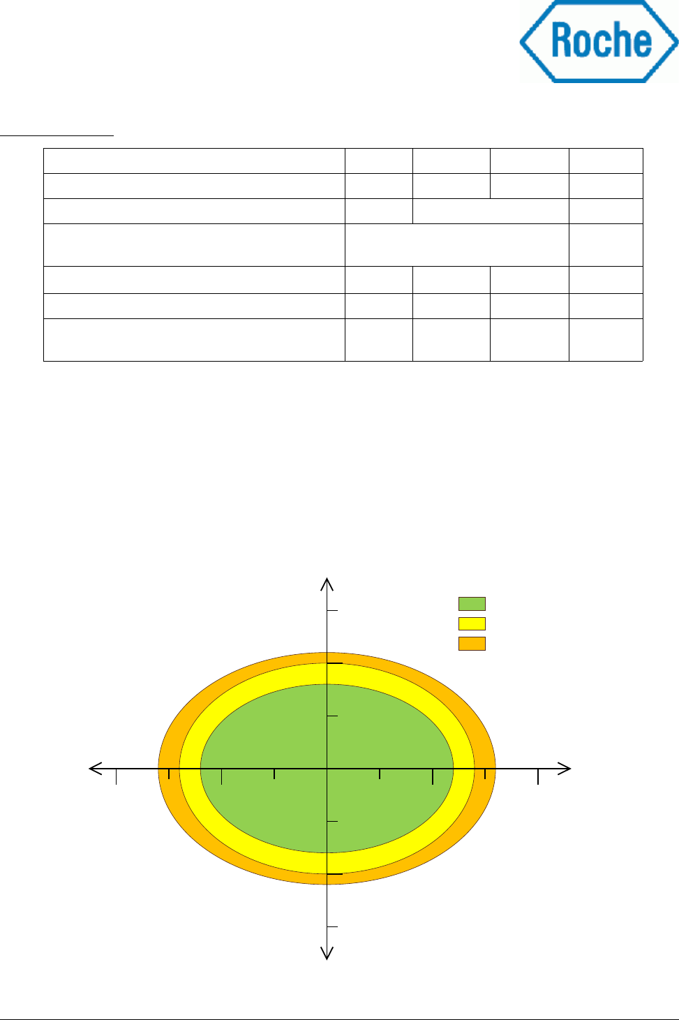
Read distance 1) dPeak 0 20 mm
Minimum distance between two labels
(centre to centre of label) to avoid cross talking
dLL 40 mm
Table 2: RFID measurement values
1) Measurement conditions: V = 5V, Transponder size = 20x10mm, Chip I-Code SLI
Transponder is converted to a label and placed on top of cassette
Read distance is measured from housing of reader to top surface of cassette
The transponder is readable over the whole operation distance between reader housing and the
specified maximum read distance
Diagram 1: Typical operation distance depending on label displacement from reader
antenna centre
5 10 15 20
-20 -15 -10 -5
0
5
10
15
-5
-10
-15
0
X-displacement
[mm]
20 mm
15 mm
10 mm
Operation ranges
Y-displacement
[mm]
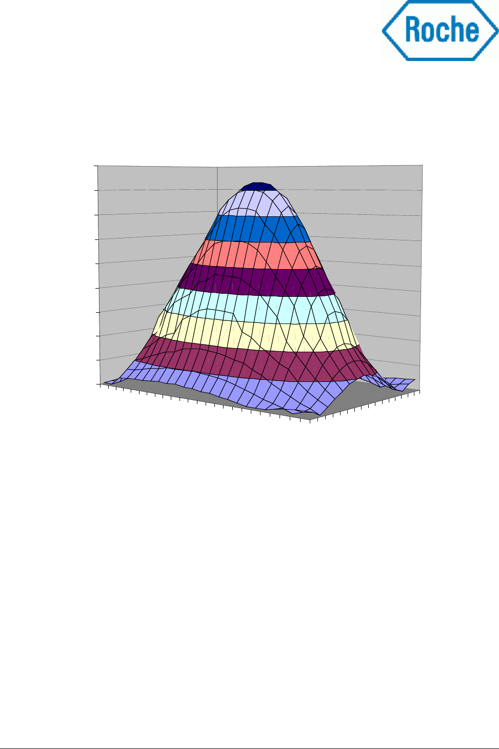
The typical field strength of the COBAS-Reader 8000 in a distance of 13 mm from the reader housing has the
following characteristic:
Delivery_Specification_COBAS_Reader_Roche_v1.1.1.odt 14 / 30
Diagram 2: Typical field strength in dependence of position under the reader measured at a distance of 13 mm measured
from bottom of reader housing
24
20
16
12
8
4
0
-4
-8
-12
-16
-20
16
12
8
4
0
-4
-8
-12
-16
0
500
1000
1500
2000
2500
3000
3500
4000
4500
Field strength
[mA/m]
X-Displacement
[mm]
Y-Displacement
[mm]
Field strength COBAS RFID reader
3.3 Optical sensors
Delivery_Specification_COBAS_Reader_Roche_v1.1.1.odt 15 / 30
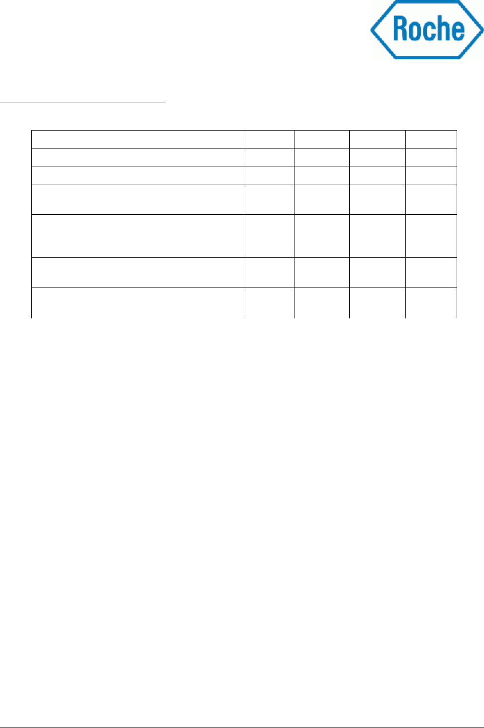
Value Symbol Min Max Unit
Current consumption per Sensor channel ISensor 25 35 mA
Wave length of sensor light λ629 661 nm
Response value “white” 1) RVwhite 250 Digits
Response value “black” 2) RVblack 100 Digits
max. displacement in X-axis 3) dX3 mm
max. displacement in Y-axis 3) dY5 mm
Settling time of sensors (measurement delay
after LED is switched on)
5 ms
Table 3: Optical sensor values
1) Measurement conditions: V = 5V, distance between sensor and white reference surface = 13 mm
2) Measurement conditions: V = 5V, distance between sensor and black reference surface = 13 mm
3) Measurement conditions: V = 5V, distance between sensor and cassette = 13 mm;
transponder label applied 2,5mm out of cassette centre (white area at cassette border)
All values are measured with both channels at one detection position switched on simultaneously. The following
commands are used: WriteOutput and ReadAnalogInput according to the document “COBAS interface protocol
v1.5”
3.4 Environmental conditions
Note: The COBAS-Reader 8000 housing is only sealed against condensing of water at the bottom of the
reader housing at normal assembly orientation in the rotor housing. No special protection against water
intrusion from all other sides is provided.
Because Hitachi has confidential internal standards the environmental tests are specified as follows:
●Rapid Change of Temperature according to EN 60068-2-14
-20°C / +75°C test temperatures
2h exposure time for upper and lower temperature
5 cycles
<10 sec. transportation time from one chamber to the other
COBAS-Reader 8000 off during test
●Cold storage according to EN 60068-2-1
+5°C exposure time
16h exposure time
1 K/min temperature changing speed from RT to test temperature
COBAS-Reader 8000 on during test
●Dry heat according to EN 600068-2-2
+35°C exposure temperature
16h exposure time
1 K/min temperature changing speed from RT to test temperature
COBAS-Reader 8000 on during test
Delivery_Specification_COBAS_Reader_Roche_v1.1.1.odt 16 / 30
Value Symbol Min Max Unit
Operation temperature range TOperation 5 +35 °C
Storage temperature range TStorage -20 +75 °C
Requested Relative humidity for storage and
operation (not condensing)
5 95 %
Requested protection against mechanical
vibration in X/Y/Z direction at full
operation 1)
2,5 m/s2
Normal operation after single shock in X/Y/Z
direction 1,
294 m/s2
Housing protection class against intrusion of
rigid particles and liquids (DIN EN 60529)
IP 20
Table 4: Environmental conditions
1) Exact specification of mechanical vibration and shock tests see below

●Damp heat, steady state, according to EN 60068-2-78
30°C exposure temperature
5% relative humidity
16h exposure time
1 K/min temperature changing speed from RT to test temperature
COBAS-Reader 8000 on during test
●Damp heat, steady state, according to EN 60068-2-78
30°C exposure temperature
95% relative humidity, non condensing
16h exposure time
1 K/min temperature changing speed from RT to test temperature
COBAS-Reader 8000 on during test
●Vibration (sinusoidal) according to EN 60068-2-6
5 Hz lower frequency
200 Hz upper frequency
0,75 mm displacement amplitude
0,25 g acceleration
9,2 Hz cross-over frequency
1 octave/minute frequency sweep
10 cycles per axis, 3 axis tested (X;Y,Z)
COBAS-Reader 8000 on during test (normally off, on requested by HHT)
●Vibration (sinusoidal) according to EN 60068-2-6
5 Hz lower frequency
200 Hz upper frequency
3,5 mm displacement amplitude
1,6 g acceleration
10,8 Hz cross-over frequency
1 octave/minute frequency sweep
10 cycles per axis, 3 axis tested (X;Y,Z)
COBAS-Reader 8000 on during test (normally off, on requested by HHT)
●Shock according to EN 60068-2-27
30 g acceleration
11 ms shock duration, half-sine pulse shape
3 shocks per direction, 6 directions tested (±X, ±Y, ±Z)
COBAS-Reader 8000 off during test
●Free fall according to EN 60068-2-32
1 procedure
300 mm fall height
1 tests per defined orientation (5 fall tests)
COBAS-Reader 8000 without packaging
COBAS-Reader 8000 off during test
Delivery_Specification_COBAS_Reader_Roche_v1.1.1.odt 17 / 30
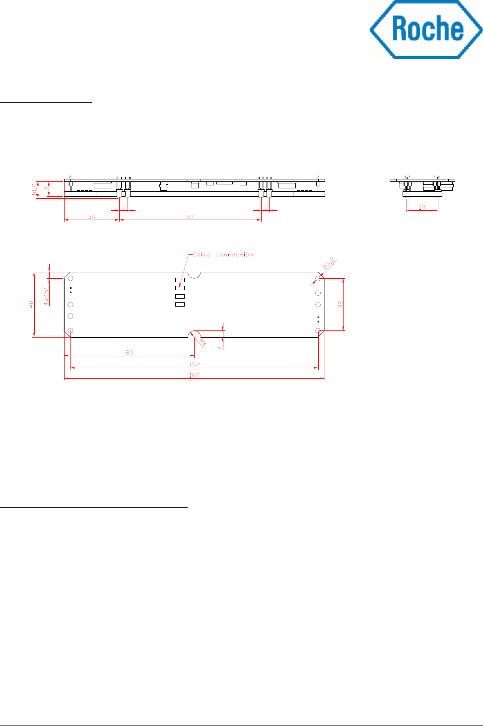
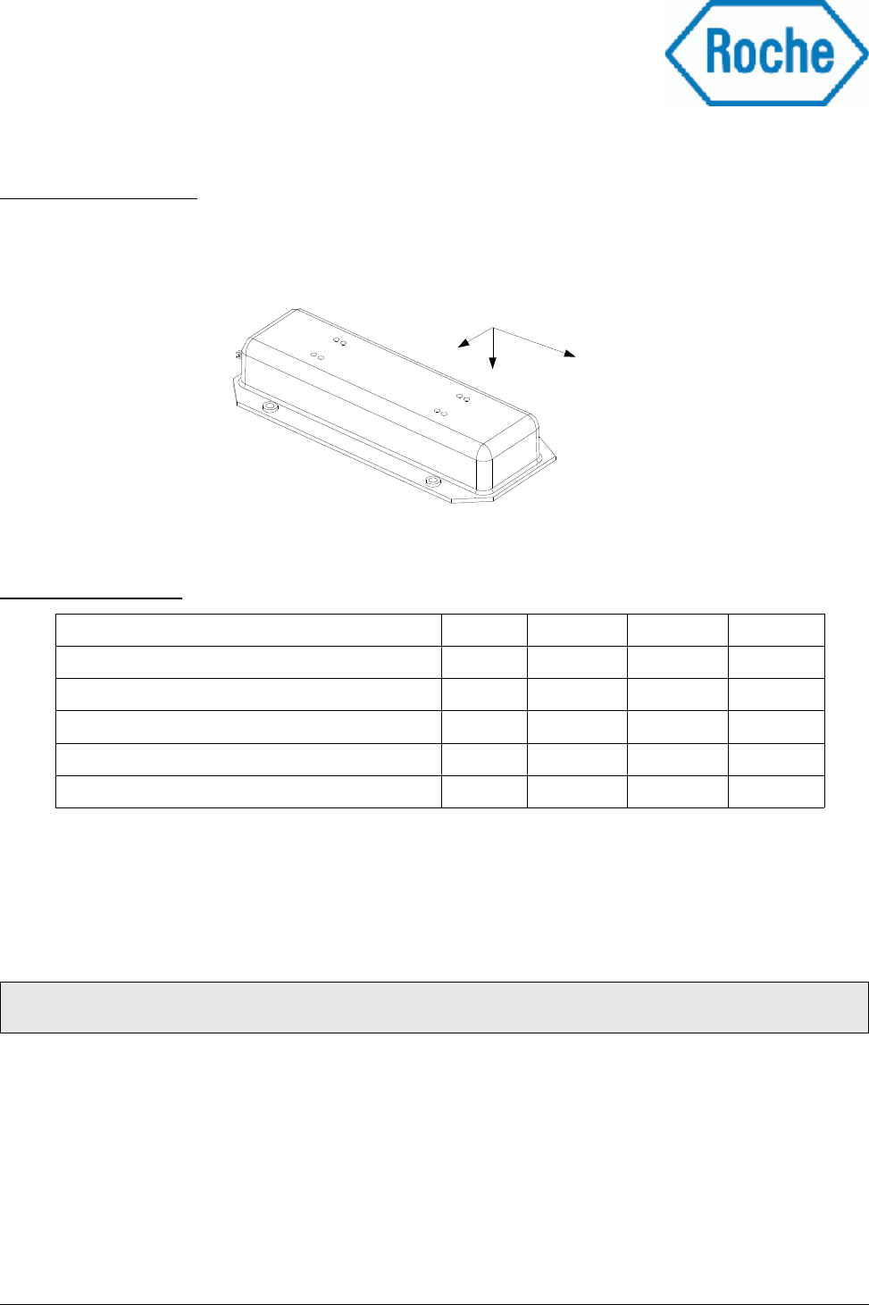
3.5 Dimensions
The PCB-Board of the COBAS-Reader 8000 has the following dimensions:
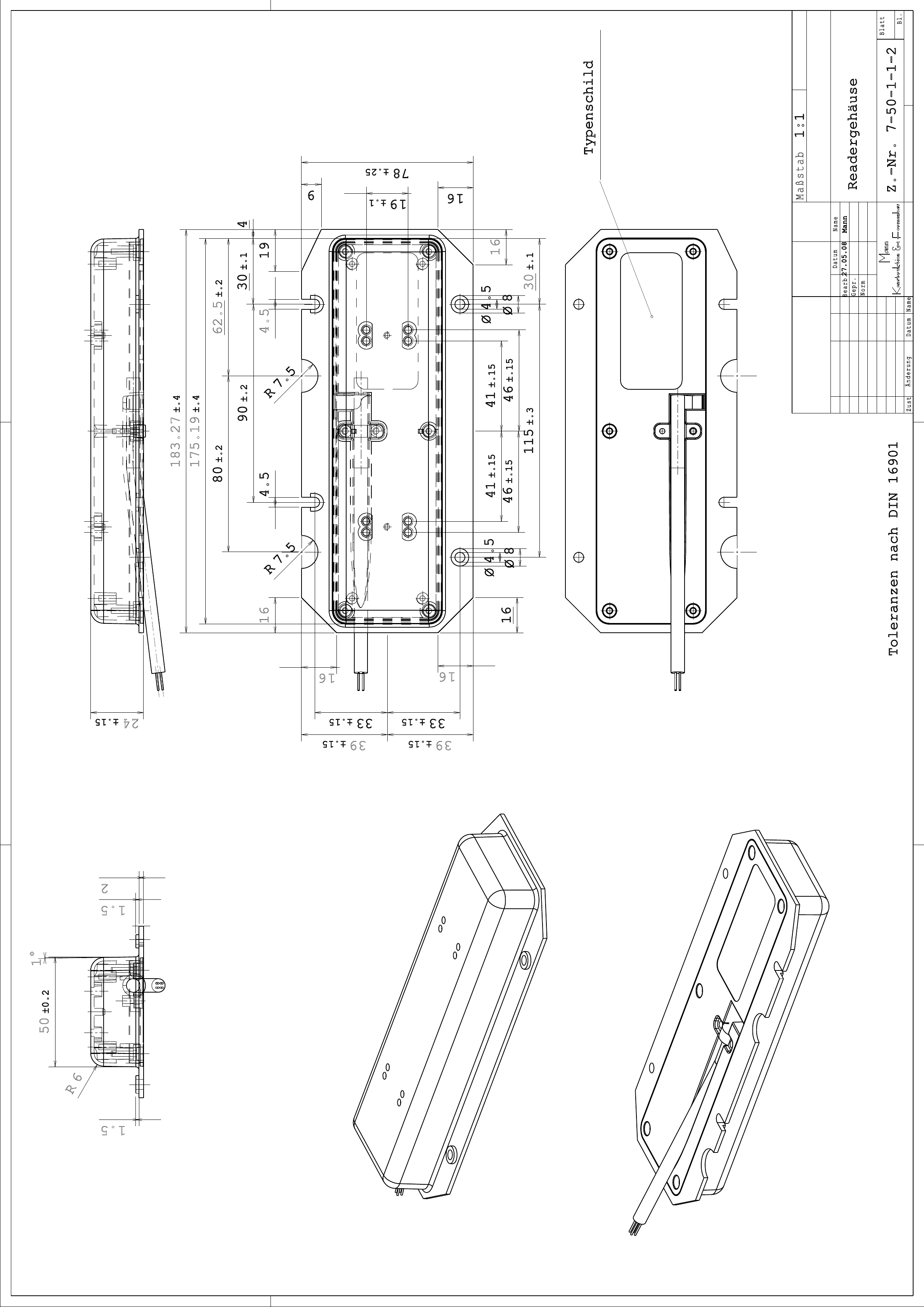
3.6 Dimensions of reader housing
The reader housing is specified in drawing no. 7-50-1-1-2 (Document “Reader housing”) .
Delivery_Specification_COBAS_Reader_Roche_v1.1.1.odt 18 / 30
Drawing 3: Final assembly of COBAS RFID reader electronic
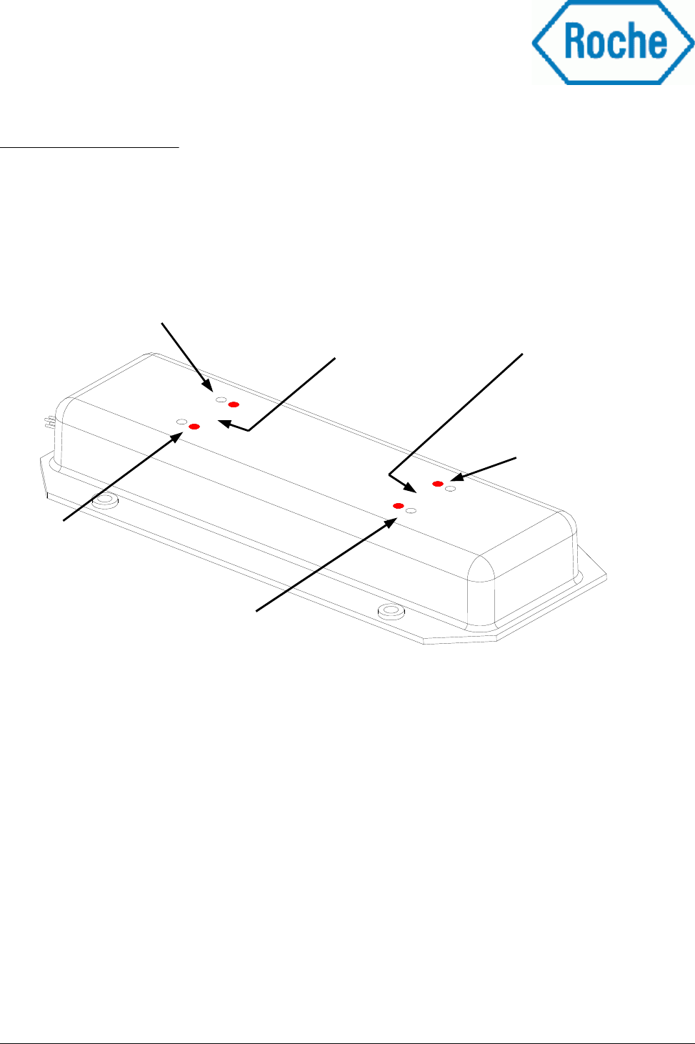
3.7 Channel positions
For correct addressing of the RFID-channels and optical sensor channels please pay attention to the following
drawing:
Delivery_Specification_COBAS_Reader_Roche_v1.1.1.odt 20 / 30
Opt. Sensor 1
Opt. Opt.
Sensor 2
Opt. Sensor 3
RFID channel 1 RFID channel 0
Drawing 4: Side view of COBAS RFID reader (red dots indicate position of LED)
Opt. Sensor 0
RFID channel 1
Opt. Sensor 1
Opt. Sensor 2
RFID channel 0
Opt. Sensor 3
3.8 Connector
The COBAS-Reader 8000 comes with a 800 mm long cable for the connection to the external host.
Cable type: UNITRONIC LiYCY UL/CSA 4x AWG22/7,
Manufacturer LAPPKABEL, order code 0044704
fire-retardant according to IEC 60332-1-2, UL VW1, CSA FT1
see Appendix 8, 9
Connector type: AMP D-2100, Product code 1318119
Drawing of cable: see attachment “Cable_v1.6.pdf” (Appendix 10)
Pin assignment:
Maximum pull force at the cable: 40 N
3.9 Serial interface parameters
The data between the COBAS-Reader 8000 and a host system are transmitted via a serial interface. The
voltage levels at the serial interface is fixed to V24-level standard, e.g. for communication with a PC.
Interface parameters:
Baud rate 19.200
No of Bits 8
Stop bit 1
Parity N
Handshake No hardware or software handshake
Delivery_Specification_COBAS_Reader_Roche_v1.1.1.odt 21 / 30
Pin Name Direction Description
A1 +5V PWR Positive supply voltage
B1 GND PWR Reference voltage level for power
supply and serial communication
A2 RxD In Receive signal from host
B2 TxD out Transmit signal to Host
A3 Shorted with cable
B3
Table 5: Pin assignment cable connector
3.10 Host communication protocol
The communication protocol between a host system and the COBAS-Reader 8000 is defined in the document
“COBAS Interface Protocol v1.5” (Appendix 11)
3.11 Life time
The analysis of the critical components and the corresponding circuitry of the COBAS-Reader 8000 resulted
in an expected life time of more than 16.000 hours of operation.
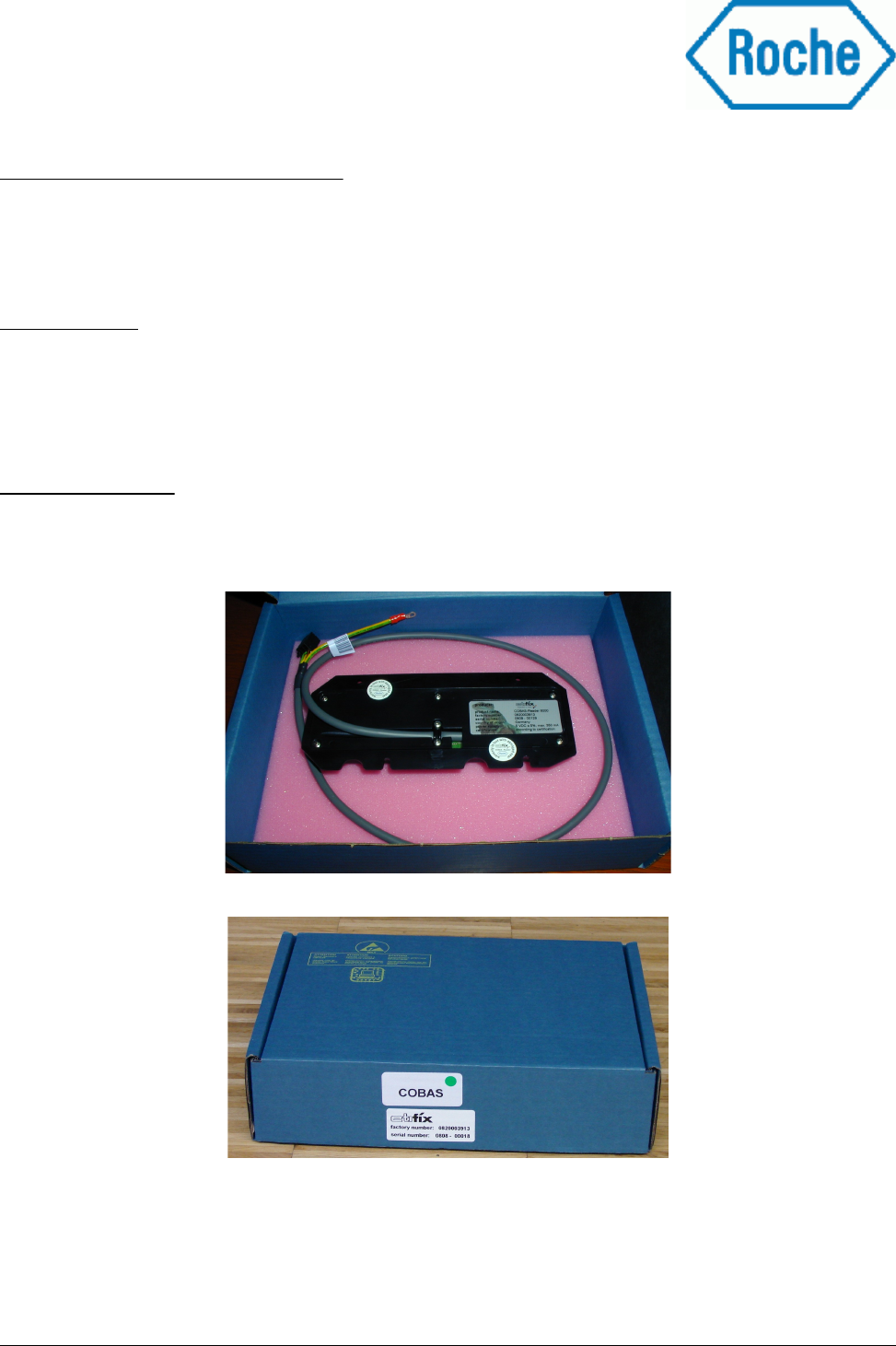
4 Packaging
Every COBAS-Reader 8000 is packed into an ESD proof carton box, protected with ESD save foam against
mechanical shocks. Each carton box is labelled with a label showing the product name and the serial number.
Delivery_Specification_COBAS_Reader_Roche_v1.1.1.odt 22 / 30
Picture 2: Packaging of COBAS RFID reader
Picture 3: Carton box with labelling

5 Embargoed countries
According to the information given from Mr. Martin, Head of division for Electronics, Optics and Sensors
(phone: 06196 / 908 – 788) at the Federal Office of Economics and Export Control in Germany are the
COBAS-Reader 8000 not restricted in any countries if they are used for medical applications as they are
designed for. The end user has to ensure that the COBAS-Reader 8000 are only used for their intent
application in the COBAS 8000 systems.
6 Installation notes
No special ESD prevention is required to assemble the COBAS-Reader 8000. It is recommend to use a ESD
wristband when you unpack the reader and connect it to the host system. The system power has to be
switched off prior to the assembly.
Be aware of the following possible environmental effects when your are installing the COBAS-Reader 8000
into a device. Also the transponders might be effected by:
•Nearby existing metal objects like housings, shielding and also PCB-boards with large ground
plates.
•EMC effects from cables
•EMC effects from magnetic fields.
Metal surface in direct vicinity of the active internal antenna will detune the antenna and thus have a direct
influence to the operating distance. Increase the distance between the antenna and the metal layer to the
possible maximum for least influence.
Communication between the reader and a transponder can never pass through a metal layer.
The optical sensors might be influenced (reduced) by condensed water on the housing of the LED / detector
components. A transparent medium should be placed on the rotor jacket cover for preventing water
condensing at the optical sensor area. The medium should be selected carefully and has to be transparent for
red light emitted by the LEDs.
Contamination by deposition of reactants on the optical sensors will reduce the reflection values for the white
and black label surface until no distinction can be made. Please take care that the sensors are periodically
cleaned.
The COBAS-Reader 8000 housing is designed to protect the reader electronics against humidity and water
condensation from the reagent rotor side. Please take care for a good sealing of the COBAS housing against
the rotor cover to prevent moisture / condensed water getting into the housing through the cable outlet.
Delivery_Specification_COBAS_Reader_Roche_v1.1.1.odt 23 / 30
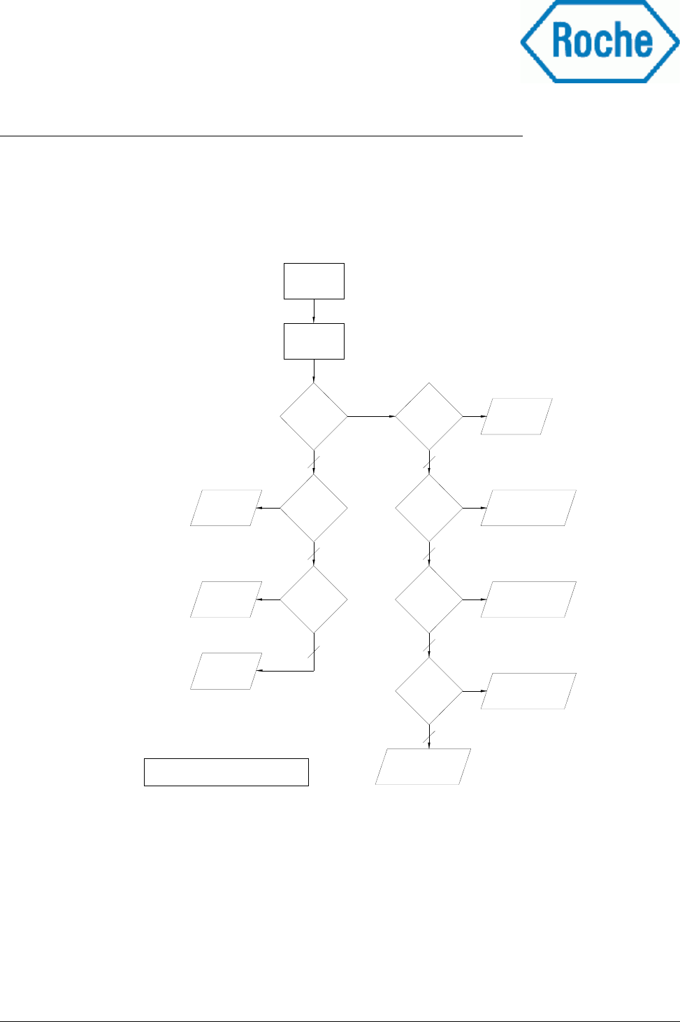
6.1 Recommended software algorithm for cassette position detection
Based on several tests done at Roche Mannheim and Roche Penzberg the following procedure for cassette
position detection is recommended. This algorithm is able to distinguish between different states.:
Depending on further evaluation the decision criteria for valid sensor signals and valid differences might
have to be adopted.
Delivery_Specification_COBAS_Reader_Roche_v1.1.1.odt 24 / 30
Picture 4: Program flow for analysis of optical sensor output
Read RFID tag
Tag readable
?
Read
optical sensors
No
-20<C<20
?
No
Empty position
Defect RFID
reader
0<R<10
?
Optical sensor
defect
C<-20
?
-20<C<20
?
No
20<C<50
?
No
Wrong cassette
orientation
No optical detection
cleaning required
Cassette orientation
correct,
cleaning required
Cassette orientation
correct
C: Contrast value (CH1-CH0 or CH3-CH2)
R: Return value of each optical sensor
No RFID
signal at all
cassettes?
No
No
Defect
RFID label
No
7 Possible interactions between the COBAS-Reader 8000 and the host
system
Several different failure modes could have an impact on the functionality of the host system. The COBAS-
Reader 8000 is designed according to best knowledge to avoid any negative interactions with an host system.
All electrical interfaces to the host system are designed in conformance to existing standards. The following
table lists possible failure modes and methods to prevent defects on the host system.
Failure mode / possible influence Protective measures
Short circuit on reader board at the
power supply
Integration of an appropriate protection circuit into the power supply
which limits the supply current to 350mA during operation
Failure at the RS232 interface, like
short or open wires
The COBAS-Reader 8000 uses an RS-232 interface driver which is
according to industrial specifications
Data failure inside the COBAS
machine due to EMC / EMV
The reader will be qualified according to international standards as
listed in chapter 2 to minimize the risk of potential influences.
Impact of the emitted RFID field to
the measurements
This effect can't be estimated and depends strongly on the
measurement methods used. Switch off the RFID antennae of the
reader before starting the measurements
Malfunction of the optical detection
due to humidity condensation
Condensed humidity reduces the responses values of the black and
white label area. Therefore software could distinguish between both
colours by measuring the relation/difference of both responses
values.
Threshold values for contrast and absolute sensor values for black
and white label areas have to be defined.
Malfunction of the optical detection
due to contamination by reactants
Periodical manual cleaning of the optical sensors by service personal
or operators
Threshold values for contrast and absolute sensor values for black
and white label areas have to be defined.
Malfunction of the optical detection
due to HF field
Due to the mechanical design of the detection channels a powered HF
field has a direct influence to the response values. For save
measurements it is strongly recommended to switch the appropriate
HF channel off before the optical sensors are read out.
Interference of optical sensors The interferences between the optical sensors CH0/CH1 or CH2/CH3
are at an absolute minimum and have no impact to the measurement.
Delivery_Specification_COBAS_Reader_Roche_v1.1.1.odt 25 / 30

8 Product warranty
etifix provides customer assistance in various technical areas, but does not have full access to data
concerning the use and applications of customer's products. Therefore, etifix assumes no liability and is not
responsible for customer applications or product or software design or performance relating to systems or
applications incorporating etifix products.
etifix assumes no liability and is not responsible for infringement of patents and/or any other intellectual or
industrial property rights of third parties, which may result from assistance provided by etifix. The electronic
circuitry and reader firmware has been checked for critical solutions and routines. etifix is not liable for
infringements of patents and/or any other intellectual or industrial property rights of third parties resulting
out of the usage in the COBAS analysis system.
etifix products are not designed, intended, authorized or warranted to be suitable for life support applications
or any other life critical applications which could involve potential risk of death, personal injury or severe
property or environmental damage. A critical component is a component used in a life-supporting device or
system whose failure can reasonably be expected to cause the failure of that life-support device or system, or
to affect its safety or effectiveness of that device or system. Life support devices or systems are intended (a)
to be implanted in the human body, or (b) to support and/or maintain and sustain human life. If they fail, it is
reasonable to assume that the health of the user may be endangered.
The product warranty is defined by governmental law and in etifix's “General Conditions for the supply of
products and services.
Delivery_Specification_COBAS_Reader_Roche_v1.1.1.odt 26 / 30
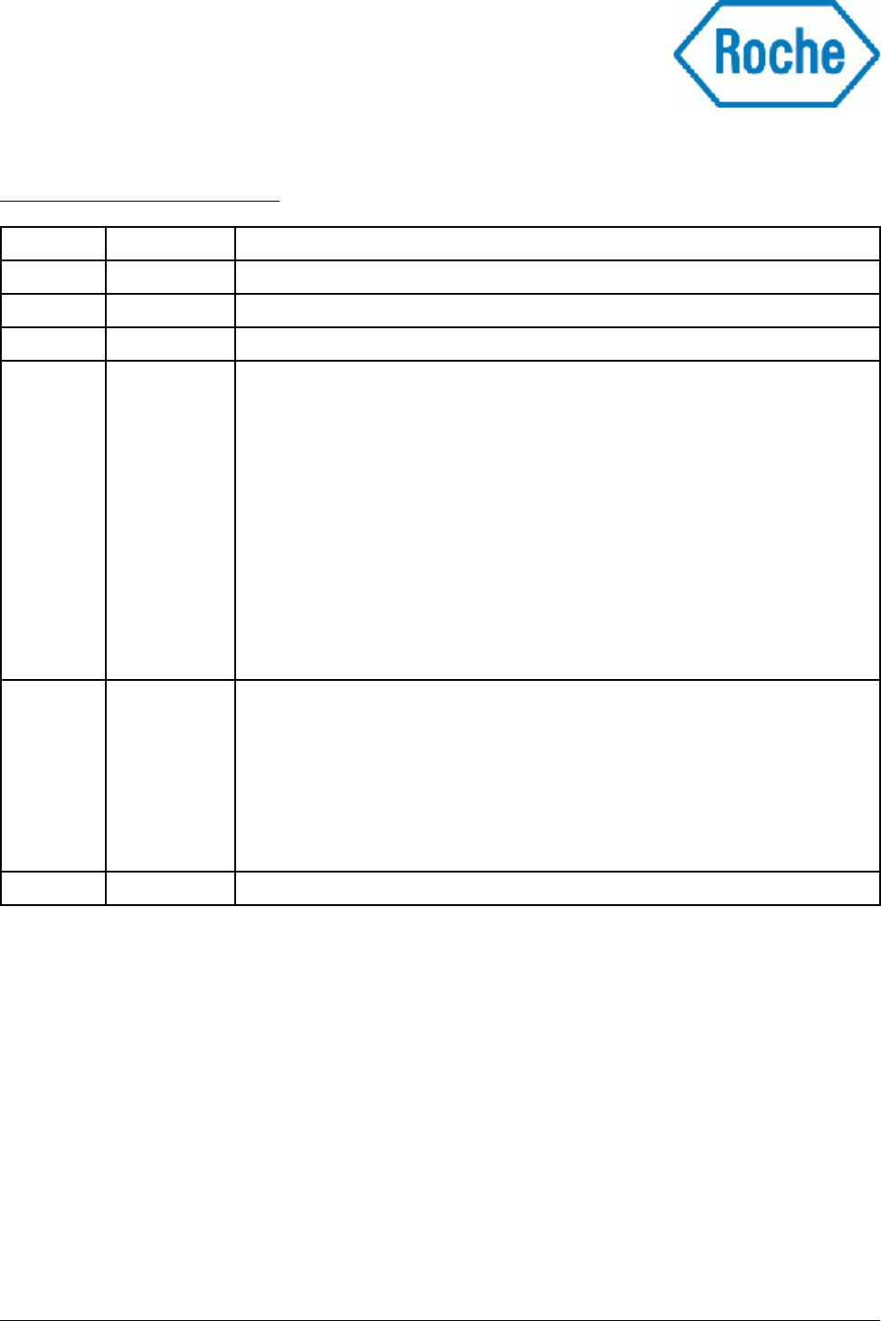
9 List of appendixes
Appendix No. Description
1 I-Code SLI SL2 ICS20, Smart Label IC, Short Form Specification, April 2002
2 I-Code SLI SL2 ICS20, Smart Label IC, Functional Specification, January 2003
3 Country list for registration RFID readers 0-series and series for c701/702
4RoHS compliance certificate
5UL Compliance certificate
6Data sheet 1.5SMC6.8AT3-D
7Behaviour of the COBAS-Reader 8000 at different supply voltages
8Data sheet of cable
9Ohmic resistance of cable
10 Cable_v1.6 specification
11 COBAS Interface Protocol v1.5
12 ISO 9001 certificate etifix
13 ISO 9001 certificate Zollner
Delivery_Specification_COBAS_Reader_Roche_v1.1.1.odt 27 / 30
10 Document revisions
Datum Version Status
27.11.07 0.1 1st draft version
31.03.08 0.2 Extension with additional requested information
0.3 Internal working paper
15.07.08 0.4 Purpose: Draft as appendix to the “Einzelentwicklungsvertrag”
§1: Changes in overall description of product, added block diagram and
identification plate layout
§2: Extension of applied standards
§3: General changes at all sub chapters
§4. Extensions
§5: Extensions
§6: Extensions
§7: Extensions
§8: Extension about raw material discontinuation
0.5 §1.4: Change of label samples, extended explanation
§3.1 Change of power supply data
§3.2 Change of RFID data
§3.3 Change of optical data
§3.4 Description of environmental tests
§3.5 Drawing of reader electronics assembly
§3.7: Correction of optical sensor position, additional 3D drawing
§3.8 Change of cable length to 800mm (future deliveries)
08.08.08 1.0 Public document for first shipment of COBAS-Reader 8000 (pre- production)
Delivery_Specification_COBAS_Reader_Roche_v1.1.1.odt 28 / 30
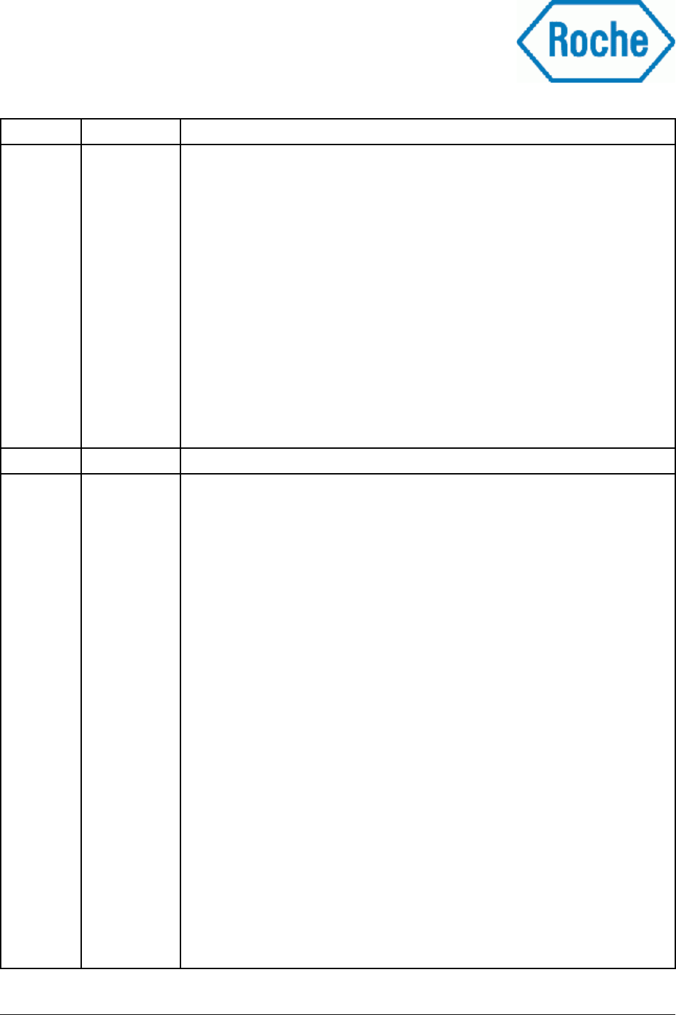
Datum Version Status
15.08.08 1.1 §1.4: Added picture of labelled reader
§2: Sentence about risks of third country certification removed, Canada
added
§3: Drawing with coordinate system showing axis of measurement values
added
§3.1: Change of data, change of recommended fuse
§3.2: Change of data, read area values at 80% of read range deleted
Diagram with operation range in dependence of position added
§3.3: Change of data, digram showing valid reflection values in dependence
on position above label added
§3.4: Standard for IP protection class added, editorial changes
§3.6: editorial changes
§3.8: Maximum pull strength of cable fixture added
§3.10:Release info of COBAS interface protocol document added
§4: Secondary packaging removed
§6: ESD handling precautions added
§7: Exchange TagStar with etifix
1.2 Working paper, not released
22.10.2008 1.3 Added Reviewer and Approval list
§1.2: Correction on position of label on cassette
§1.3: Correction of product name
§1.4: Change of picture of labelling
Added drawing about position of labels
§2.0: Intern. Compliance certifications are excluded to this document
§3.1: Added behaviour at different supply voltages
Added notice about over voltage
§3.2: Change of RF output power
Adding diagram of HF field strength
§3.3: Change of X/Y limits of acceptable label displacement
Adoption of black/white limits to new label surface
Sensor values measured simultaneously
§3.6: Implementation of housing drawing
§3.7: Removed drawing form bottom side, added LED position at optical
sensors
§3.8: Interface cable drawing changed from v1.2 to v1.4 (length tolerance,
mounting ring, additional pins A3, B3)
§3.10: Changed document version of interface protocol to 1.5
§3.11: Added topic Expected life time
§4: Added pictures about packaging
§5: Embargoed countries (none)
§6: Editorial change at water condensation protection
§7: Adopted value for recommended external fuse at power line
Definition of threshold values recommended
§8: Extension of intellectual property rights and exclusion of life supporting
devices
§9: Added topic Table of appendixes
Delivery_Specification_COBAS_Reader_Roche_v1.1.1.odt 29 / 30
Datum Version Status
05.02.2009 1.4 General name change of the reader to COBAS-Reader 8000 (change from
development project name to product name)
§1.2: Remove over voltage protection from block diagram
Wording misleading, see chapter 3.1
§1.4: Exchange of identification label to newer design
(corrected max. current consumption 300 → 350mA)
§2: Extension and correction of radio regulations and standards according to
granted certificates
§3.1: max. standby current consumption changed from 55mA to 70mA caused
by review of first 150 readers.
Change of wording for over voltage protection
§3.4: Change of Damp heat testing standard from sub part 30 (dynamic
humidity change during test) to sub part 78 (static humidity during test)
as qualification test have been done and certified.
§3.11:Change Expected life time → Life Time
§6.1: Added chapter: Recommended software algorithm for cassette position
detection
§7: Change of wording for protective measures against short circuit and
failures at communication interface
10.02.2009 1.4.1 §1.4: Correction of identification plate picture (same plate as shown in other
pictures used in this document)
§3.1: Removed annotation about Reader reset threshold voltage
Voltage will be measured at production testes
§3.2: Removed annotation “Not verified at mass production” at diagram 1 and
diagram 2
§3.8: Removed annotation “Not verified at mass production” at value for
maximum pull force applied to the cable
§ 8: Removed clause about discontinuation of raw material. Has to be
defined in delivery contract.
Removed misspelling in sentence about critical solutions and routines.
17.02 1.5 Removal of HHT from the list of document approvals
§3.1: Misleading wording about suppressor diode deleted
Delivery_Specification_COBAS_Reader_Roche_v1.1.1.odt 30 / 30