Rockwell Collins 2703240 VRS User Manual
Rockwell Collins, Inc. VRS
User Manual
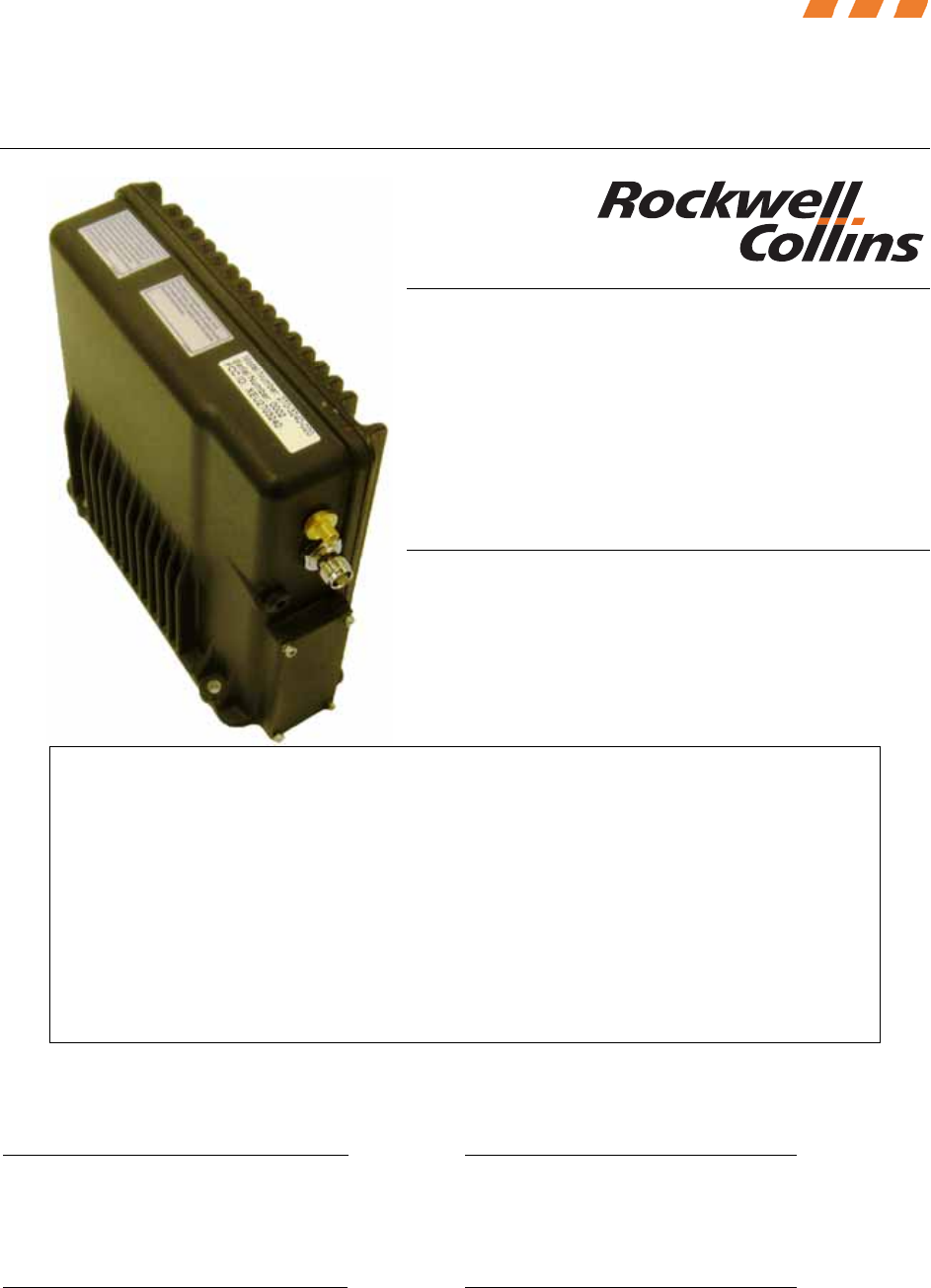
Vehicle Repeater System Module
Installation Manual
Rockwell Collins, Inc. – Proprietary Information. i
Vehicle Repeater System Module
270-3240-020
Installation Manual
Proprietary Notice
NOTICE: The contents of this document are proprietary to Rockwell Collins, Inc. and
shall not be disclosed, disseminated, copied, or used except for purposes expressly
authorized in writing by Rockwell Collins, Inc.
Export Notice
The technical data in this document (or file) is controlled for export under the Export
Administration Regulations (EAR), 15 CFR Parts 730-774. Violations of these export
laws may be subject to fines and penalties under the Export Administration Act.
© Copyright 2009 Rockwell Collins, Inc. All rights reserved.
Prepared by: Approved by:
_________________________ ________________________
Dave Philipp Date Deborah Braid Date
System Engineer Technical Project Manager
Approved by: Approved by:
_________________________ ________________________
Cris Johnson Date Jason Heimer Date
Engineering Manager Program Manager

Vehicle Repeater System Module
Installation Manual
Rockwell Collins, Inc. – Proprietary Information. ii
This page is intentionally left blank.

Vehicle Repeater System Module
Installation Manual
Rockwell Collins, Inc. – Proprietary Information. iii
FCC COMPLIANCE
This device complies with Part 15 of the FCC Rules. Operation is subject to the following two
conditions:
1. This device may not cause harmful interference
2. This device must accept any interference received, including interference that may
cause undesired operation.
WARNING: For compliance with FCC RF Exposure Requirements, the mobile transmitter
antenna installation shall comply with the following two conditions:
1. The transmitter antenna gain shall not exceed 3 dBi.
2. The transmitter antenna is required to be located outside of a vehicle and kept at a
separation distance of 10 inches or more between the transmitter antenna of this
device and persons during operation.
WARNING: CHANGES OR MODIFICATIONS NOT EXPRESSLY APPROVED BY
ROCKWELL COLLINS COULD VOID THE USER'S AUTHORITY TO OPERATE
THE EQUIPMENT.
Note: This equipment has been tested and found to comply with the limits for a Class A
digital device, pursuant to part 15 of the FCC Rules. These limits are designed to provide
reasonable protection against harmful interference when the equipment is operated in a
commercial environment. This equipment generates, uses, and can radiate radio frequency
energy and, if not installed and used in accordance with the instruction manual, may cause
harmful interference to radio communications. Operation of this equipment in a residential
area is likely to cause harmful interference in which case the user will be required to correct
the interference at his own expense.
Note: If the FCC ID is not visible when the module is installed inside another device, then
the outside of the device into which the module is installed must also display a label
referring to the enclosed module. This exterior label can use wording such as the following:
"Contains Transmitter ModuleFCC ID: XEU2703240" or "Contains FCC ID: XEU2703240."
CAUTION
This unit contains static sensitive devices. Wear a grounded wrist strap and/or conductive
gloves when handling printed circuit boards.

Vehicle Repeater System Module
Installation Manual
Rockwell Collins, Inc. – Proprietary Information. iv
TABLE OF CONTENTS
1.0 General Description........................................................................................ 1
1.1 Scope ....................................................................................................... 1
1.2 Technical Characteristics.............................................................................. 1
1.3 Environmental Testing Summary................................................................... 1
2.0 Interface Control Drawing ............................................................................... 2
2.1 Definitions ................................................................................................. 2
2.2 P25 Vehicle Repeater System Interface Definition............................................ 3
2.2.1 P25 VRS Antenna Connectors................................................................. 4
2.2.2 P25 VRS DB-44 Connector..................................................................... 4
3.0 Installation Control Drawing ............................................................................ 6
4.0 Acronyms ..................................................................................................... 8

Vehicle Repeater System Module
Installation Manual
Rockwell Collins, Inc. – Proprietary Information. v
LIST OF FIGURES
Figure 1 – ICD Drawing Key ...................................................................................... 2
Figure 2 – P25 VRS System Connection....................................................................... 4
Figure 3 – P25 VRS TNC Antenna Connector (Dims in mm) ............................................ 4
Figure 4 – P25 VRS SMA Antenna Connector (Dims in mm)............................................ 4
Figure 5 – P25 VRS DB-44 Connector.......................................................................... 5
Figure 6 – P25 VRS Outline Drawing (dims in inches).................................................... 7

Vehicle Repeater System Module
Installation Manual
Rockwell Collins, Inc. – Proprietary Information. vi
LIST OF TABLES
Table 1 – Technical Characteristics of Transceiver boards .............................................. 1
Table 2 – Environmental Summary............................................................................. 1
Table 3 – P25 VRS DB-44 Connector Definition............................................................. 5
Table 4 – Acronym List for VRSM Installation Manual..................................................... 8

Vehicle Repeater System Module
Installation Manual
Rockwell Collins, Inc. – Proprietary Information. vii
Document Production Software
The following software was used to produce this document.
Word Processor: Microsoft Word
Drawings: Microsoft Visio
Revision History
Date Originator Reason for Change
7/31/09 D. Philipp Baseline Document
8/07/09 D. Philipp Revised Information
8/08/09 D. Philipp Revised Information

Vehicle Repeater System Module
Installation Manual
Rockwell Collins, Inc. – Proprietary Information. 1
1.0 GENERAL DESCRIPTION
1.1 SCOPE
This document provides the installation instructions of the Rockwell Collins Vehicle
Repeater System Module (VRSM), part number 270-3240-020. The unit is intended
for use by government agencies or contractors thereto whom have obtained licensing
within the frequency range listed in Table 1 below.
The Rockwell Collins VRSM is a full duplex P25 radio module consisting of two Nexus
XR25 transcievers capable of operating in the 764 MHz to 869 MHz frequency range.
The VRSM has the ability to operate in both analog and digital communications.
The purpose of the VRSM is to allow a portable radio to transmit and interface with a
moble radio while repeating the transmission to other portable radios in the area on
the selected channel. The VRSM is capable of programming frequency, CTCSS tones,
and P25 Network Access Codes (NAC) information. In addition, the RF power output
can be adjusted from 0.1W to 2.0W to reduce interference with other nearby systems.
1.2 TECHNICAL CHARACTERISTICS
The VRSM consists of two identical transceiver boards. Table 1 describes the high
level specifications for the transceiver.
Table 1 – Technical Characteristics of Transceiver boards
Feature Figure
Tx Frequency Range 769.15 MHz to 770 MHz
Rx Frequencey Range
769.15 MHz to 770 MHz and
799.15 MHz to 800 MHz
Channel Spacing 12.5 kHz/25kHz
Modulation
Narrowband Analog FM/ Wideband
Analog FM/ P25 Digital Voice and
Data
RF Output Power 0.1W – 2W
Voltage Required 9.0 – 19.0 Volts
Amperage Required 4 Amps Max
Operating Temperature -20° C to +60°C
1.3 ENVIRONMENTAL TESTING SUMMARY
Table 2 shows the environmental testing of the VRSM.
Table 2 – Environmental Summary
Standard Title/Section
MIL-STD-810F 514.5 Procedure I (Vibration)
Vehicle Repeater System Module
Installation Manual
Rockwell Collins, Inc. – Proprietary Information. 2
MIL-STD-810F 516.5 Procedure I (Shock)
MIL-STD-810F 506.4 Procedure II (Rain)
MIL-STD-810F 510.4 Procedure I (Sand and Dust)
MIL-STD-810F 509.4 Procedure I (Salt Fog)
MIL-STD-810F 502.4 Procedure I & II (Low Temperature)
MIL-STD-810F 501.4 Procedure I & II (High Temperature)
MIL-STD-810F 507.4 Procedure I (Humidity)
2.0 INTERFACE CONTROL DRAWING
2.1 DEFINITIONS
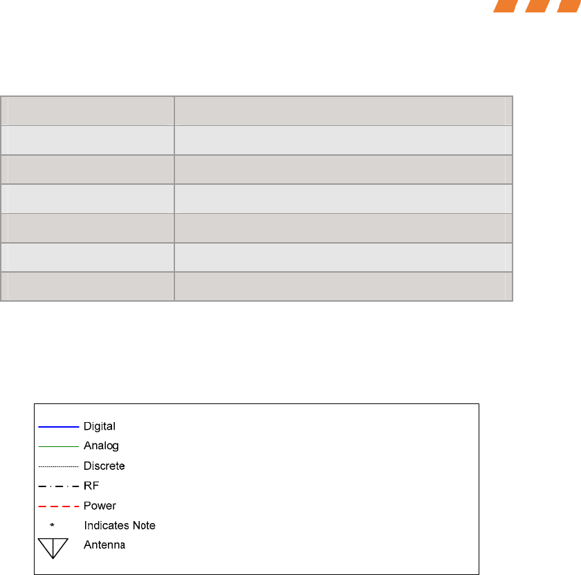
For the drawings in this ICD, Figure 1 below defines the key for each drawing.
Figure 1 – ICD Drawing Key
For the tables in this ICD, the following definitions shall be used:
Function: Function is the description of the pin(s) and what data should be expected
from it. Function should include what protocol and/or intended use. Function usually
is fairly descriptive of the function being performed on that pin or set of pins, i.e.
“Mobile PTT Output”, or “RS-232.”
Signal Type: Signal Type is the kind of signal/message being sent. Signal Types can
be Ground, Analog, Serial Digital, G/O Discrete, RF, 12VDC Battery, etc.
I/O: I/O is the direction of the signal, I (Input), O (Output), or G (Ground Return).
Pin: Pin is the physical pin or wire number on the connector. It may also be the wire
color in the cases where pins are not numbered.
Comments: Comments will contain any information pertinent to the pin. This might
include voltage levels, current limits, impedance limits, wire types, or even a longer
description of the intended use of the pin.
Vehicle Repeater System Module
Installation Manual
Rockwell Collins, Inc. – Proprietary Information. 3
2.2 P25 VEHICLE REPEATER SYSTEM INTERFACE DEFINITION
This Interface Control Drawing (ICD) provides a description of the interfaces within
the VRSM. Logical interfaces are defined as digital communication paths represented
by industry digital standards such as the EIA/TIA/RS-232 standard. The ICD provides
connection diagrams, and pin descriptions with logical interface protocol information.
The VRSM contains a pair of RF connectors to interface with antennas. These
connectors are detailed out in Section 2.2.1. Internally, all interfaces on the XR-25
transceiver boards are brought out to a single connector. Each transceiver board has
an RF side and a digital side, where the single connector is brought out on the digital
side. The connector is referred to as the “host interface connector.” Each of the two
transceiver boards will reside on a carrier board within the module housing. The
carrier board will provide power filtering, audio attenuation, and digital signal level
conversion. The carrier board has the power and data connections to the external
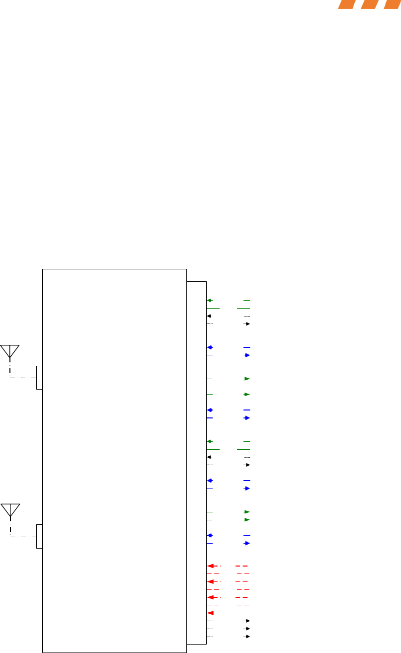
surface which is detailed in 2.2.2. Figure 2 below details the connection of the VRS to
the system.
DB-44 PIN
VRS Module
CPN 270-3240-020
Etherstack Transceivers and Carrier Board
MIC Audio Output
PTT Output
Transmit Data*
Analog Status RSSI Input
Analog Status RSSI Input?
Analog Audio Received Audio Input
*Note – Control and Radio Programming are accomplished through the serial connections.
Ground Ground
Digital Status Qualified Audio Present Input
Digital Signal Receive Data*
Power
Power Output
Digital Signal Transmit Data*
Digital Signal Receive Data*
MIC Audio Output (NOT USED)
PTT Output (NOT USED)
Ground (NOT USED)
Digital Signal
Digital Audio Input
Digital Signal
Digital Status Qualified Audio Present Input
Digital Signal
Power
I2C_PWR
SCL_COMDigital Status
Digital Status SDA_COM
Digital Status POK_COM
Ground
Power Ground
Power
Power Output
Ground
Power Ground
Analog Audio Received Audio Input
Analog Audio
Digital Control
Ground
Digital Control
Analog Audio
Digital Signal
Digital Signal
Digital Audio Output
Digital Audio Input
Digital Audio Output
Power
Power Output
Ground
Power Ground
TNC SMA
Vehicle Repeater System Module
Installation Manual
Rockwell Collins, Inc. – Proprietary Information. 4
Figure 2 – P25 VRS System Connection
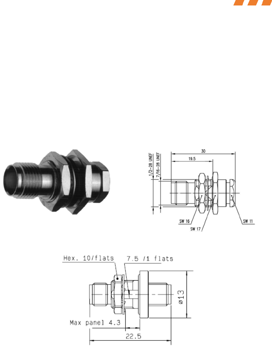
2.2.1 P25 VRS ANTENNA CONNECTORS
There are two antenna connectors on the P25 VRSM. One is a TNC type connector
(Figure 3) and the other is a SMA type connector (Figure 4). These antenna ports
shall not be connected to an antenna with a gain greater than 3dBi.
Internally, these connectors attach via cabling to the individual transceiver cards
inside the VRSM. The TNC connector is a TNC Bulkhead Jack G3 (RG-178B/U), IP 67
rated, Telegärtner brand connector, part number J01011A2336. The SMA connector
is a SMA female-female hermetic bulkhead adaptor, Radiall brand connector, part
number R125.753.000.
Figure 3 – P25 VRS TNC Antenna Connector (Dims in mm)
Figure 4 – P25 VRS SMA Antenna Connector (Dims in mm)
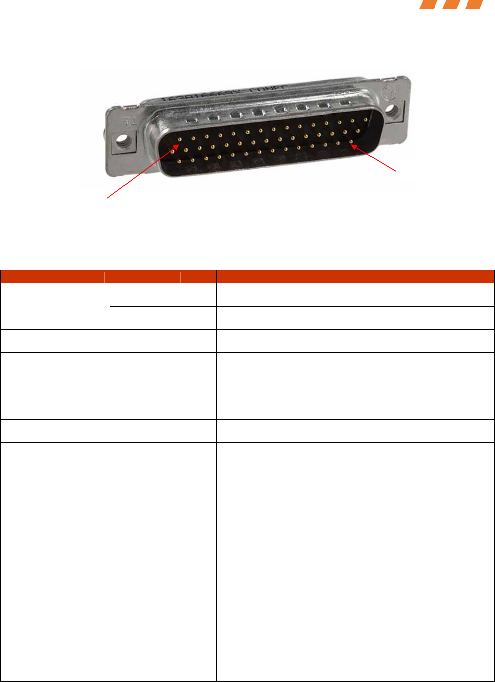
2.2.2 P25 VRS DB-44 CONNECTOR
The DB-44 Connector on the P25 VRSM is defined in Figure 5. The DB-44 Connector
is a CONEC brand, part number 6HDD44PCY99R40X.
Vehicle Repeater System Module
Installation Manual
Rockwell Collins, Inc. – Proprietary Information. 5
Figure 5 – P25 VRS DB-44 Connector
Electrical signal characteristics of the DB-44 connector are listed in Table 3.
Table 3 – P25 VRS DB-44 Connector Definition
Function Signal Type I/O
Pin Comments
Analog Audio I 35 300mV RMS 60% deviation
MIC Audio Input 1 Ground G 21 Ground
PTT Input 1 CMOS I 40 3.3V signal (0.8V low ) 1K load Max, Driven Open
Collector from the BCM
TTL RXD I 14 UART control and programming to VRS module 1
from BCM. This signal should be non-inverted. 3.3V
signal (0.8V low 2.0V high) 1K load
RS232 – Radio
Control &
Programming 1 TTL TXD O 15 UART control and programming from VRS module 1
to BCM. This signal should be non-inverted. 3.3V
signal (0.4V low 2.4V high) 4ma drive
Qualified Audio
Present Output 1 CMOS O 42
3.3V signal (0.4V low 2.4V high) 4ma drive –
Programmable to be Active High or Active Low
Analog Audio
1 O 35 300mV RMS 60% deviation
Analog Audio
2 O 36 300mV RMS 60% deviation
Received Audio
Output 1 & 2
Ground G 24 Analog Input Audio Ground
UART TXD O 9 UART digital audio stream from VRS module 1 to
BCM. This signal should be non-inverted. 3.3V
signal (0.4V low 2.4V high) 4mA drive
Digital Audio 1
UART RXD I 6 UART digital audio stream to VRS module 1 from
BCM. This signal should be non-inverted. 3.3V
signal (0.8V low 2.0V high) 1K load
Analog Audio I 36 300mV RMS 60% deviation
MIC Audio Input 2 Ground G 37 Ground
PTT Input 2 CMOS I 41
3.3V signal (0.8V low ) 1K load Max, Driven Open
Collector from the BCM
RS232 – Radio
Control & TTL RXD I 29 UART control and programming to VRS module 2
from BCM. This signal should be non-inverted. 3.3V
signal (0.8V Low 2.0V High) 1K load
Pin 1
Pin 44

Vehicle Repeater System Module
Installation Manual
Rockwell Collins, Inc. – Proprietary Information. 6
Function Signal Type I/O
Pin Comments
Programming 2 TTL TXD O 30 UART control and programming from VRS module 2
to BCM. This signal should be non-inverted. 3.3V
signal (0.8V low 2.0V high) 4mA drive
Qualified Audio
Present Output 2 CMOS O 43
3.3V signal (0.4V low 2.4V high) 4ma drive –
Programmable to be Active High or Active Low
UART TXD O 8 UART digital audio stream from VRS module 2 to
BCM. This signal should be non-inverted. 3.3V
signal (0.4V low 2.4V high) 4mA drive
Digital Audio 2
UART RXD I 5 UART digital audio stream to VRS module 2 from
BCM. This signal should be non-inverted. 3.3V
signal (0.8V low 2.0V high) 1K load
12V Power I 31 9V to 19V, 4A current limit
12V Power I 32 9V to 19V, 4A current limit
12V Power I 33 9V to 19V, 4A current limit
Ground G 1 VRS board power return signal
Ground G 16 VRS board power return signal
Power Input
Ground G 17 VRS board power return signal
I2C_POW Power I 19
I2C 3.3V Power. This power is only used for the
EEPROM and the Temp Sensor on the VRS module.
Current limited and controlled by the MCM on the
BCM.
SCL_COM G/O Discrete O 18 I2C data clock for the EEPROM and the Temp
Sensor. This signal is part of the module detection.
3.3V signal.
SDA_COM G/O Discrete O 3 3.3V Signal (08V Low, 2.0V High), 1K Load. I2C
Data Bus for the EEPROM and the Temp Sensor.
This signal is part of the module detection.
POK_COM G/O Discrete O 34
Active high power OK signal to the MCM. Should
indicate all power supplies are good on the VRS
modules. 3.3V signal (0.4V low 2.4V high) 1ma
drive
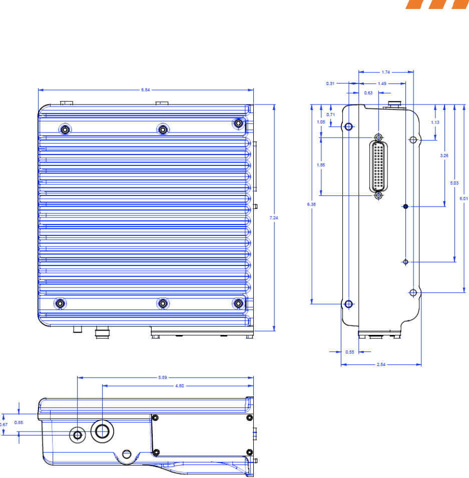
3.0 INSTALLATION CONTROL DRAWING
Figure 6 below shows the overall outline drawing (physical dimensions) of the VRSM.
The drawing details out the centerlines of all connectors on the external surface.
Vehicle Repeater System Module
Installation Manual
Rockwell Collins, Inc. – Proprietary Information. 7
Figure 6 – P25 VRS Outline Drawing (dims in inches, not to scale)

Vehicle Repeater System Module
Installation Manual
Rockwell Collins, Inc. – Proprietary Information. 8
4.0 ACRONYMS
Table 4 – Acronym List for VRSM Installation Manual
Acronym Definition
A Ampere
BNC Bayonet Neill-Concelman
dBi decibel isotropic
EEPROM Electrically Erasable Programmable
Read-Only Memory
G Ground Return
I Input
ICD Interface Control Drawing
kHz Kilohertz
ma Milli-Amp
MIC Microphone
mm Millimeters
O Output
POK_Comm Power
PTT Push to Talk
RMS Root Mean Square
RSSI Received Signal Strength
Indication
RXD Receive Digital
SCL_Comm Serial Clock
SDA_Comm Serial Data
SMA Sub-Miniature version A
TNC Threaded Neill-Concelman
TXD Transmit Digital
UART Universal Asynchronous
Receiver/Transmitter
VRS Vehicle Repeater System
VRSM Vehicle Repeater System Module
W Watt