Rockwell Collins 8221468 Dual Channel Spacing Aeronautical Transceiver User Manual Production Test Requirements
Rockwell Collins Inc Dual Channel Spacing Aeronautical Transceiver Production Test Requirements
Contents
- 1. Users Manual
- 2. Production Test Requirements
Production Test Requirements

Blank Doc Document Sample components
CPN ###-####-### Rev -CC2912 Rockwell Collins, Inc - Proprietary InformAtionPage 1
PRODUCTION TEST REQUIREMENTS – EXHIBIT N
Production Test Requirements
For the
VHF-4000
And
VDL-2000
CPN: 827-4660-001
DP-XX-YY
DEP- 005
1 OCT 2001
NOTICE: The contents of this document are proprietary to Rockwell
Collins, Inc. and shall not be disclosed, disseminated, copied, or
used except for purposes expressly authorized in writing by
Rockwell Collins, Inc.
Rockwell Collins, Inc.
Cedar Rapids, Iowa 52498 USA
CAGEC: 4V792
PTR for VHF-4000 and VDL-2000 Data Radios
____________________________________________________________________________
©2000 Rockwell Collins, Inc Page 2 of 61
Notices and Signatures
Name Signature / Date
Prepared By:
Project Engineer K.H. Hamby
Approved By:

PTR for VHF-4000 and VDL-2000 Data Radios
____________________________________________________________________________
©2000 Rockwell Collins, Inc Page 3 of 61
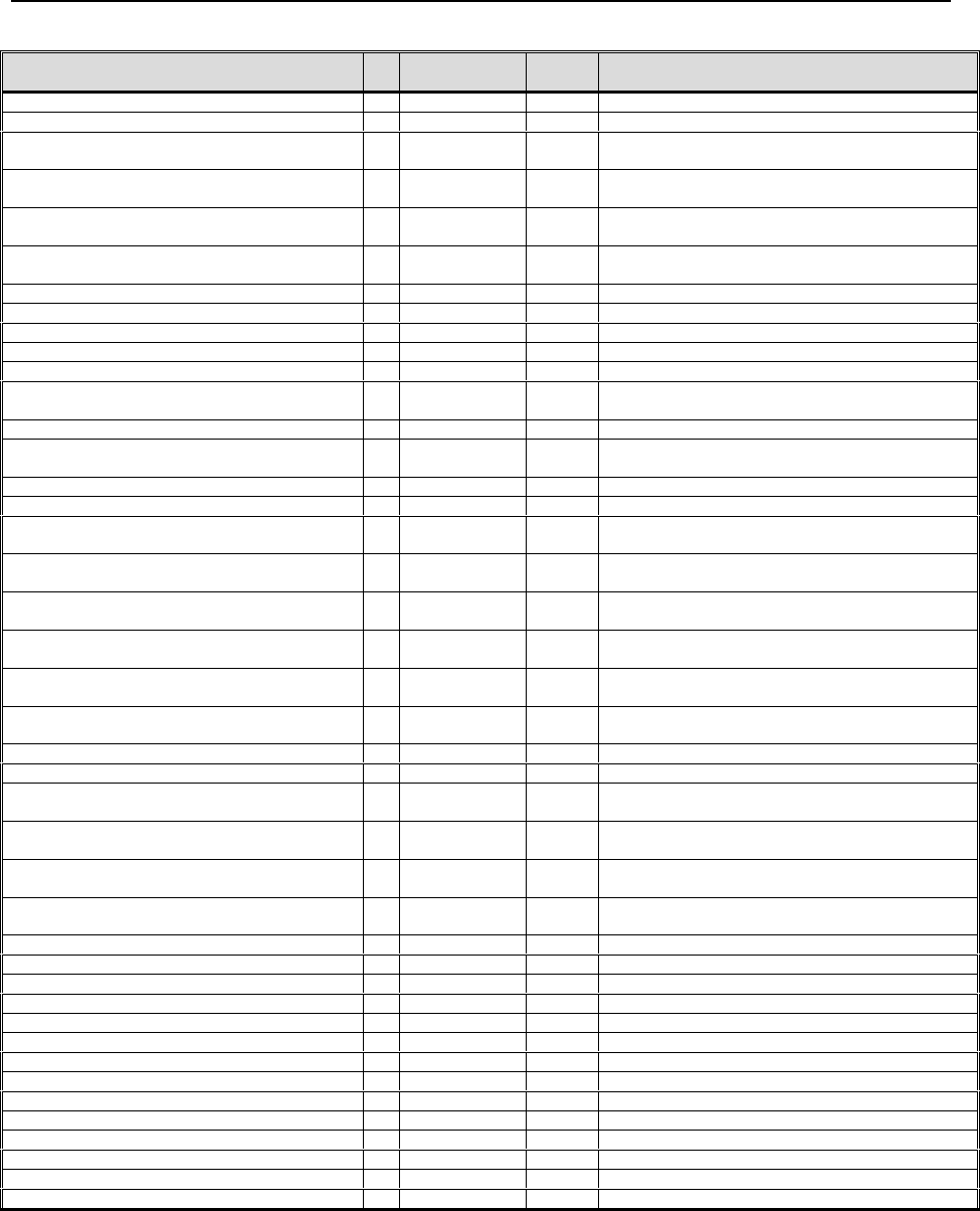
Revision History
Version Document
Date
Originator Reason for Change
14 Feb 01
4 May 01
15 Aug 01
1 Oct 01
KKH
KKH
KKH
FJS
DEP-002
DEP-003
DEP-004
DEP-005

PTR for VHF-4000 and VDL-2000 Data Radios
____________________________________________________________________________
©2000 Rockwell Collins, Inc Page 4 of 61
Review History
Version Document Date Reviewer

PTR for VHF-4000 and VDL-2000 Data Radios
____________________________________________________________________________
©2000 Rockwell Collins, Inc Page 5 of 61
TABLE OF CONTENTS
Notices and Signatures ................................................................................................................... 2
Revision History .............................................................................................................................. 3
Review History................................................................................................................................. 4
TABLE OF CONTENTS.................................................................................................................. 5
1. Scope........................................................................................................................................ 8
2. Reference Information.............................................................................................................. 8
2.1 Specifications..................................................................................................................... 8
2.2 Drawings ............................................................................................................................ 8
2.2.1 VHF-4000 .................................................................................................................... 8
2.2.2 VDL-2000..................................................................................................................... 8
2.3 Operating Frequencies VS ICAO Channel Designators ................................................... 8
3. Test Equipment Required......................................................................................................... 9
4. Test Conditions......................................................................................................................... 9
4.1 Temperature....................................................................................................................... 9
4.2 Humidity ............................................................................................................................. 9
4.3 Warm-up and Initialization ................................................................................................. 9
4.4 Atmospheric Pressure........................................................................................................ 9
4.5 Transmit Duty Cycle......................................................................................................... 10
5. Test Definitions and Information............................................................................................. 10
5.1 Standard Discrete Configuration...................................................................................... 10
5.2 Standard RF Generator Configuration............................................................................. 10
5.3 Standard ARINC 429 Bus/Data Configurations............................................................... 11
5.3.1 Standard Control Data Configurations...................................................................... 11
5.3.2 Standard Data Configurations................................................................................... 11
5.4 Test Sequence................................................................................................................. 11
6. Alignment................................................................................................................................ 12
6.1 Software Load Procedure ................................................................................................ 12
6.2 Calibration and TFM Parameters..................................................................................... 12
6.2.1 Initialization of Calibration Parameters ..................................................................... 12
6.2.2 Initialization of TFM Parameters ............................................................................... 13
6.3 Alignment Procedures...................................................................................................... 14
6.3.1 Receiver Analog Audio Output Level (VHF4000 Only) [Rx Cal] .............................. 14
6.3.2 Selcal Audio Output Level (VHF4000 Only) [Rx Cal] ............................................... 15
6.3.3 Voice Carrier Null [Tx TFM]....................................................................................... 15
6.3.4 Voice/Analog Data Bias Adjustment [Tx TFM] ......................................................... 15
6.3.5 +28 V Transmitter Phasing Adjustment [Tx TFM] .................................................... 15
6.3.6 +20 V Transmitter Phasing Adjustment [Tx TFM] .................................................... 16
6.3.7 Preselector Adjustments [Rx Cal] ............................................................................. 16
6.3.8 Analog Voice/Data Unmodulated Transmitter RF Power [Tx TFM] ......................... 16
6.3.9 Simulcomm 0 Adjustment (-20 dBm threshold) [Rx TFM]........................................ 17
6.3.10 Simulcomm 1 Adjustment (-10 dBm threshold) [Rx TFM]........................................ 17
6.3.11 Analog Voice/Data Transmitter Modulation [Tx TFM] .............................................. 17
6.3.12 Simulcomm 2 Adjustment ( 0 dBm threshold) [Rx TFM].......................................... 17
6.3.13 Analog and Digital Sidetone Levels [Tx Cal]............................................................. 18

PTR for VHF-4000 and VDL-2000 Data Radios
____________________________________________________________________________
©2000 Rockwell Collins, Inc Page 6 of 61
6.3.14 Squelch Adjustment .................................................................................................. 18
6.3.15 Mode A Alignment (Units/w Mode A Option Only).................................................... 19
6.3.16 Mode 2 Alignment (Units/w Mode 2 Option Only) .................................................... 19
6.3.17 Mode 2 AGC Calibration ........................................................................................... 20
6.3.18 Flash Update ............................................................................................................. 20
7. Final Test Requirements ........................................................................................................ 20
7.1 Power Supplies ................................................................................................................ 21
7.1.1 Current Drain at 27.5 Vdc ......................................................................................... 21
7.1.2 Current Drain at 18.0 Vdc ......................................................................................... 21
7.1.3 Internal Power Supplies ............................................................................................ 21
7.2 Voice/Analog Data Mode Tests ....................................................................................... 21
7.2.1 Voice/Analog Data Receiver Tests ........................................................................... 21
7.2.2 Voice/Analog Data Mode Transmitter Tests............................................................. 30
7.2.3 Data Bus Operation................................................................................................... 37
7.2.4 429_Input_Port_C, Port_C_Sel, Unit_SDI_A_Sel, and Unit_SDI_B_Sel(VHF-4000
only) 37
7.2.5 429_MAINT_HS_IN .................................................................................................. 38
7.2.6 429_MAINT_HS_OUT .............................................................................................. 38
7.2.7 CSDB_IN and CSDB_OUT (VHF-4000 only)........................................................... 38
7.2.8 422_DATA_OUT and 422_DATA_IN (VDL-2000 only)............................................ 38
7.3 Discrete I/O Tests ............................................................................................................ 38
7.3.1 TX_MODE_IND......................................................................................................... 38
7.3.2 Data_Load_Enbl_Sel ................................................................................................ 38
7.3.3 WOW_Sel.................................................................................................................. 39
7.3.4 Burst_Tune_Sel......................................................................................................... 39
7.3.5 Voice/Data_Sel.......................................................................................................... 39
7.3.6 RX_Comp_Disbl_Sel (VHF4000 Only)..................................................................... 39
7.3.7 RIU_Installed_Sel (VHF-4000 only).......................................................................... 39
7.3.8 All_Call_Disable_Sel (VHF-4000 only)..................................................................... 39
7.3.9 SIMULCOM_CNTL_1_SEL ...................................................................................... 39
7.3.10 SIMULCOM_CNTL_2_SEL ...................................................................................... 39
7.3.11 SYSTEM_ON_F (VDL-2000 only) ............................................................................ 40
7.4 ARINC 429 I/O Tests (VHF4000 Only!)........................................................................... 40
7.4.1 VHF ARINC 429 Low Speed Output Port 1.............................................................. 40
7.4.2 VHF ARINC 429 Low Speed Output Port 2.............................................................. 41
7.4.3 VHF ARINC 429 High Speed Output Port 1............................................................. 42
7.4.4 VHF ARINC 429 High Speed Output Port 2............................................................. 43
7.5 Selftest (VHF4000 Only).................................................................................................. 44
7.6 Vibration (Perform on a sample basis only!) .................................................................. 44
7.7 Talk Out/Voice (Perform on a sample basis only!).......................................................... 44
7.8 Mode A Tests (Units/w Mode A Option Only)................................................................. 44
7.9 Mode 2 Tests (Units/w Mode 2 Option Only) .................................................................. 44
7.9.1 Load application Software (CPN: 822-1468-985 Only) ............................................ 44
7.9.2 Mode 2 Receiver Tests (Units/w Mode 2 Option Only) ............................................ 44
7.9.3 Mode 2 Transmitter Tests ......................................................................................... 45
8. Temperature Testing .............................................................................................................. 46
8.1 Selftest (VHF4000 Only, Performed during the rapid cycle portion of ESS).................. 46
8.2 Parametric Tests (VHF4000 Only, performed during the extended dwell portions of
ESS) 47
8.2.1 Receiver:.................................................................................................................... 47

PTR for VHF-4000 and VDL-2000 Data Radios
____________________________________________________________________________
©2000 Rockwell Collins, Inc Page 7 of 61
8.2.2 Transmitter:................................................................................................................ 47
Appendix A Alignment Formats .................................................................................................... 49
Appendix B Rear Connector Pins by Function............................................................................. 54
Appendix C - VDL Mode 2 Operation ........................................................................................... 58

PTR for VHF-4000 and VDL-2000 Data Radios
______________________________________________________________________
______
©2000 Rockwell Collins, Inc Page 8 of 61
1. Scope
These production test requirements apply to the VHF-4000 Transceiver, CPN 822-1468-xxx and VDL-
2000, CPN 822-1603-001.
2. Reference Information
2.1 SPECIFICATIONS
VHF-4000 Equipment Specification, CPN: 832-6673-001
VHF-4000 Unit Interface Specification, CPN: 832-8567-001
VDL-2000 Equipment Specification, CPN: TBD
VDL-2000 Unit Interface Specification, CPN: TBD
2.2 DRAWINGS
2.2.1 VHF-4000
RF Card Assembly (A1), CPN: 828-3186-XXX
DSP/PS Card Assembly (A2), CPN: 828-3187-XXX
Rear Interconnect Card Assembly (A3), CPN: 828-3185-XXX
2.2.2 VDL-2000
RF Card Assembly (A1), CPN: 828-3310- XXX
DSP Card Assembly (A2), CPN: 828-3311-xxx XXX
Interconnect Card Assembly (A3), CPN: 828-3312- XXX
Power Supply Assembly (A4), CPN 828-3313- XXX
2.3 OPERATING FREQUENCIES VS ICAO CHANNEL DESIGNATORS
For all test frequencies listed in test setups in this report, the ICAO Channel Identification
developed for the 8.33 kHz channels is used. The channel identification will not
necessarily reflect the actual operating frequency. Table 4.7-1 shows the relationship
between ICAO Channel Identification, actual operating frequency, receiver bandwidth,
and ARINC 429 frequency control word. NOTE: Narrow Band (NB) is selectivity for
8.33 kHz channels and Wide Band (WB) is selectivity for 25 kHz channels.
Table 4.7-1
Frequency (MHz) ICAO Channel
Name ARINC 429
Control Word
Content
ARINC 429
Control Word
Label
Receiver IF
Bandwidth
automatically
selected by
unit
118.0000 118.000 118.000 030 WB
118.0000 118.005 118.000 047 NB
118.0083 118.010 118.008 047 NB
118.0167 118.015 118.017 047 NB
118.0250 118.025 118.025 030 WB
118.0250 118.030 118.025 047 NB
118.0333 118.035 118.033 047 NB
PTR for VHF-4000 and VDL-2000 Data Radios
______________________________________________________________________
______
©2000 Rockwell Collins, Inc Page 9 of 61
Frequency (MHz) ICAO Channel
Name ARINC 429
Control Word
Content
ARINC 429
Control Word
Label
Receiver IF
Bandwidth
automatically
selected by
unit
118.0417 118.040 118.042 047 NB
118.0500 118.050 118.050 030 WB
118.0500 118.055 118.050 047 NB
118.0583 118.060 118.058 047 NB
118.0667 118.065 118.067 047 NB
118.0750 118.075 118.075 030 WB
118.0750 118.080 118.075 047 NB
118.0833 118.085 118.083 047 NB
118.0917 118.090 118.092 047 NB
118.1000 118.100 118.100 030 WB
118.1000 118.105 118.100 047 NB
136.9750 136.975 136.975 030 WB
136.9750 136.980 136.975 047 NB
136.9833 136.985 136.983 047 NB
136.9917 136.990 136.992 047 NB
3. Test Equipment Required
The following test equipment or equivalent is required:
1. CATS-21 Full ATE
2. Lab View 5.1.1 DLS-001
3. Test Stand 1.02 DLT-001
4. I.E Test Exec. 3.1.1 DLR-001
4. Test Conditions
Unless otherwise specified, all tests shall be performed under the following conditions:
4.1 TEMPERATURE
Normal factory ambient.
4.2 HUMIDITY
Normal factory ambient.
4.3 WARM-UP AND INITIALIZATION
30 seconds
4.4 ATMOSPHERIC PRESSURE
Normal factory ambient.

PTR for VHF-4000 and VDL-2000 Data Radios
______________________________________________________________________
______
©2000 Rockwell Collins, Inc Page 10 of 61
4.5 TRANSMIT DUTY CYCLE
20 %, 30 seconds maximum single transmit duration
5. Test Definitions and Information
• In transmit mode, the antenna output shall be terminated in 50
ohm load and the sidetone audio output terminated in 600 ohm
load. In receive mode, receiver and data audio outputs are
terminated in 600 ohm load.
• All receiver RF levels are in dBm at UUT antenna input.
• Upper limit of operation at ICAO channel 136.990 applies for
some units. Disregard operation beyond this frequency in any
alignment or tests where frequencies exceeding this limit are
specified.
• Connect TX_Mode_Indicator (VHF-4000 Pin 47, VDL-2000 Pin 3)
to 27.5 Vdc through a 270 ohm, ½ watt load.
5.1 STANDARD DISCRETE CONFIGURATION
The “Standard Discrete Configuration” is defined as the following configuration of the input discretes:
DISCRETE VHF-4000
Pin # VDL-2000
Pin # STATUS
PTT_Sel 41 35 Open (Receive mode)
Simulcom_Cntl_1_Sel
Simulcom_Cntl_2_Sel 42
46 16
34 Open (Attenuator disabled)
Open
RIU_Installed_Sel 43 NA Open (RIU not installed)
All_Call_Dsbl_Set 44 NA Open (All-Call enabled)
Voice/Data_Sel 45 17 Open (Voice mode)
Burst_Tune_Sell 49 NA Open (Continuous tuning)
ARINC/CSDB Select 50 NA Open (ARINC-429 control selected)
Port_C_Sel 51 NA Open (ARINC 429 Input Port C not
selected)
RX_Comp_Dsbl_Sel 52 NA Open (Receive compressor disabled)
Port_A/B_Sel 55 NA Open (ARINC 429 Input Port B
selected)
Unit_ID_A_Sel
Unit_ID_B_Sel 56
62 15
18 Open (All-Call enabled *)
Open
WOW_Sel 57 14 Open (Weight on Wheels not selected)
Data_Load_Enbl_Sel 61 29 Open (Data Load disabled)
SYSTEM_ON_F NA 27 Gnd (Transceiver On)
5.2 STANDARD RF GENERATOR CONFIGURATION
The “Standard RF Generator Configuration” is defined as follows:
Generator set to the frequency defined at time of reference, amplitude modulated
by a 1 kHz sine wave at a modulation level of 30%, and a RF level of –47 dBm.

PTR for VHF-4000 and VDL-2000 Data Radios
______________________________________________________________________
______
©2000 Rockwell Collins, Inc Page 11 of 61
5.3 STANDARD ARINC 429 BUS/DATA CONFIGURATIONS
5.3.1 Standard Control Data Configurations
5.3.1.1 VHF-4000
All test steps are performed using continuous tuning on the low speed ARINC 429 control bus
429_Input_Port_B (Pins 3 and 4). The control words are labels 030 for 25 kHz channels & 047 for 8.3
kHz channels.
Calibration and TFM parameters are set using the high-speed maintenance input bus MAINT_IN (Pins 9
and 10) and output port MAINT_OUT (Pins 13 and 14). The control word is label 277 (See Appendix for
format).
5.3.1.2 VDL-2000
All test steps are performed using continuous tuning on the high-speed ARINC 429 maintenance input bus
429MAINT_IN (pins 1 and 32). The control words are labels 030 for 25 kHz channels & 047 for 8.3 kHz
channels.
Calibration and TFM parameters are also set using the high-speed ARINC 429 maintenance input bus
429MAINT_IN (pins 1 and 32). The control word is label 277 (See Appendix for format).
5.3.2 Standard Data Configurations
• The “Standard 25 kHz ARINC Configuration” is defined as follows:
Octal label 047 (8.33 kHz label) set to NCD.
Transmit the control data on label 030 (Oct) every 200 ms.
The tuning channel will be defined at the time of reference to this definition.
The SSM is set to 11 (squelch disabled).
SDI set to 00 (All call).
• The “Standard 8.33 kHz ARINC Configuration” is defined as follows:
Octal label 030 (25 kHz label) set to NCD.
Transmit the control data on label 047 (Oct) every 200 ms.
The tuning channel will be defined at the time of reference to this definition.
The SSM is set to 11 (squelch disabled).
SDI set to 00 (All call).
5.4 TEST SEQUENCE
If the UUT has never been aligned then all alignment steps must be performed in sequence. For re-
alignment of UUT as a result of a repair action or modification, perform only alignment steps of circuits
that have been effected by repair action or modification. Checksum will be automatically updated
whenever FLASH memory is updated.
PTR for VHF-4000 and VDL-2000 Data Radios
______________________________________________________________________
______
©2000 Rockwell Collins, Inc Page 12 of 61
6. Alignment
Connect main connector plug from test station to UUT.
Apply 27.5 ± 0.5 Vdc to the power input.
VHF-4000, power pins 58, 64 and ground pins 59, 65.
VDL-2000, power pins 10, 11 and ground pins 8, 9.
Wait 30 seconds for the unit to complete power on testing.
The VHF4000 or VDL2000 may be aligned per Section 6.3 Alignment Procedures or with the automatic
alignment system (CATS-21) executing DGS-005.
6.1 SOFTWARE LOAD PROCEDURE
Load the desired top-level software using the data loader capability of the VHF-4000 or the boundary scan
interface.
6.2 CALIBRATION AND TFM PARAMETERS
The VHF-4000 uses electronic alignment for circuits that use values for various parameters stored in
FLASH memory. TFM parameters are those that require different values depending upon temperature,
frequency or mode. Calibration parameters are those that are the same for all temperature, frequency, and
mode.
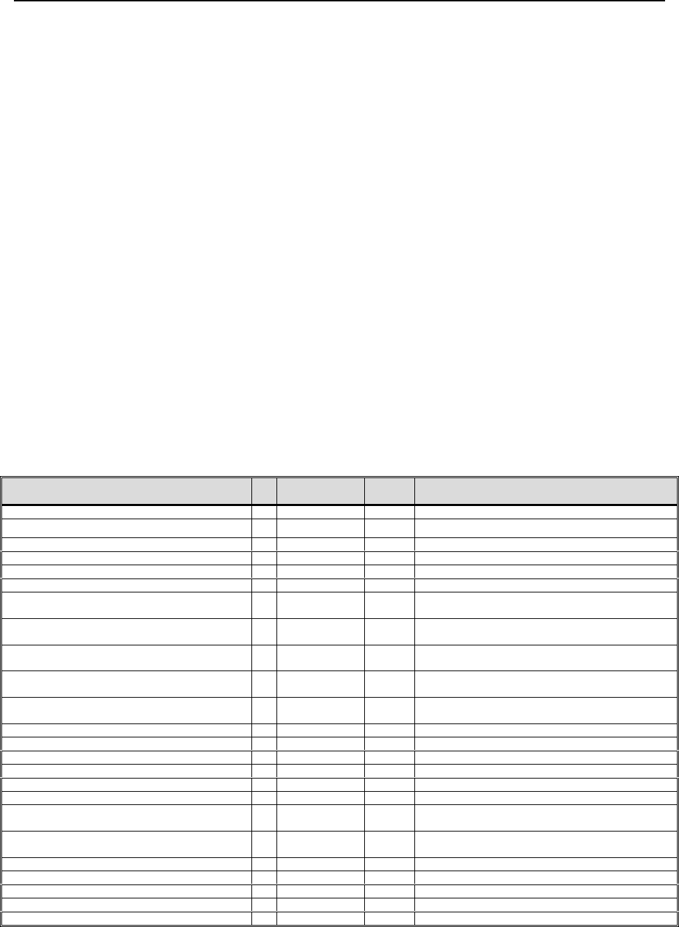
6.2.1 Initialization of Calibration Parameters
Store into FLASH memory the hex values for calibration parameters listed in the following table or the
nominal value (nominal values derived from trend data).
Calibration Parameter #Applicable
Mode Value
(hex) Notes
Combined Audio Level Adjust 43 Rx 4268 level adjust for combined audio Rx output
Digital Audio Level Adjust 44 Rx 23E7 level adjust for digital audio Rx output
Rx Compressor Threshold 45 Rx 250F input level threshold for receiver compressor
Carrier Squelch Mute Threshold 46 Rx 7FFF Carrier Squelch muting upper limit
Carrier Squelch Unmute Threshold 47 Rx 7FFF Carrier Squelch unmuting upper limit
25 kHz Noise Squelch Mute Threshold 48 Rx 7FFF 25 kHz Noise Squelch muting upper limit
25 kHz Noise Squelch Unmute
Threshold 49 Rx 0000 25 kHz Noise Squelch unmuting lower limit
8.33 kHz Noise Squelch Mute
Threshold 50 Rx 7FFF 8.33 kHz Noise Squelch muting upper limit
8.33 kHz Noise Squelch Unmute
Threshold 51 Rx 0000 8.33 kHz Noise Squelch unmuting lower limit
138.6 MHz Noise Squelch Mute
Threshold 52 Rx FFFF 138.6 MHz Noise Squelch muting upper limit
138.6 MHz Noise Squelch Unmute
Threshold 53 Rx 0000 138.6 MHz Noise Squelch unmuting low limit
Digital Audio Sidetone Level Adjust 54 Tx 2C76 level adjust for digital audio sidetone output
Combined Audio Sidetone Level Adjust 55 Tx 1C39 level adjust for combined audio sidetone out
Low Voltage Scaling Threshold 56 Tx 07D0 low volt limit for signal scaling in transmits
VSWR Scaling Threshold 57 Tx 4E20 VSWR limit for signal scaling in transmits
Analog Tx Compressor Threshold 58 Tx 6DE level to begin analog Tx signal compression
Digital Audio Tx Compressor Threshold 59 Tx 07FF level to begin digital Tx signal compression
Tx Power Upper Threshold for all but
Mode 2 60 Tx 07FF V Fwd high limit for non-Mode 2 Tx faults
Tx Power Lower Threshold for all but
Mode 2 61 Tx 0000 V Fwd low limit for non-Mode 2 Tx faults
Tx Power Upper Threshold for Mode 2 62 Tx 07FF V Fwd high limit for Mode 2 Tx faults
Tx Power Lower Threshold for Mode 2 63 Tx 0000 V Fwd low limit for Mode 2 Tx faults
VSWR Fault Threshold 64 Tx 7FFF VSWR limit for reporting of faults
PA Over Temperature Threshold 65 Tx 0783 PA temperature limit at which Tx is aborted
+3.3 VDC Upper Threshold 66 Rx/Tx 09C5 fault upper limit for +3.3 VDC input value
PTR for VHF-4000 and VDL-2000 Data Radios
______________________________________________________________________
______
©2000 Rockwell Collins, Inc Page 13 of 61
Calibration Parameter #Applicable
Mode Value
(hex) Notes
+3.3 VDC Lower Threshold 67 Rx/Tx 0698 fault lower limit for +3.3 VDC input value
+8.0 VDC Upper Threshold 68 Rx/Tx 0A7A fault upper limit for +8.0 VDC input value
+8.0 VDC Lower Threshold 69 Rx/Tx 0649 fault lower limit for +8.0 VDC input value
-8.0 VDC Upper Threshold 70 Rx/Tx 0965 fault upper limit for -8.0 VDC input value
-8.0 VDC Lower Threshold 71 Rx/Tx 05A3 fault lower limit for -8.0 VDC input value
+5.0 VDC Upper Threshold 72 Rx/Tx 0CF6 fault upper limit for +5.0 VDC input value
+5.0 VDC Lower Threshold 73 Rx/Tx 06FA fault lower limit for +5.0 VDC input value
+15.0 VDC Upper Threshold 74 Rx/Tx 0A79 fault upper limit for +15.0 VDC input value
+15.0 VDC Lower Threshold 75 Rx/Tx 06FB Fault lower limit for +15.0 VDC input value
Tx Timeout Threshold 76 Tx 3FFF limit at which Tx is aborted
TFM Temperature Boundary A 77 Rx/Tx 01C1 Sets TFM temperature zones 1 & 2 boundary
TFM Temperature Boundary B 78 Rx/Tx 0364 Sets TFM temperature zones 2 & 3 boundary
TFM Temperature Boundary C 79 Rx/Tx 0508 Sets TFM temperature zones 3 & 4 boundary
TFM Temperature Hysteresis 80 Rx/Tx 33 Hysteresis for descending temp zone transits
VSWR Scaling Coefficient 81 Tx 571C Power reduction to apply for VSWR scaling
SELCAL Audio Level Adjust 82 Rx 5654 Level adjust for SELCAL audio DAC output
Low V IQ Phase Adj. Upper Threshold 83 Tx 0000
(TBD
new
value
28V val. to start Low Voltage IQ Phase Adjust
Low V IQ Phase Adj. Lower Threshold 84 Tx 0000
(TBD
new
value
28V val. to end Low Voltage IQ Phase Adjust
SW AGC Selftest Limit On Threshold 85 Rx 7FFF SW AGC level max limit with signal present
SW AGC Selftest Limit Off Threshold 86 Rx 0000 SW AGC level min limit with signal absent
HW AGC Selftest Limit On Threshold 87 Rx 0000 HW AGC level max limit with signal present
HW AGC Selftest Limit Off Threshold 88 Rx 7FFF HW AGC level min limit with signal absent
Transfer Fault Tone Level Adj. 89 Rx/Tx 12C Audio level of fault
D8PSK Low Voltage Scaling Threshold 90 Tx 0000
(TBD
new
value )
Low volt limit for signals scaling in transmit in D8PSK
modes.
I_Q _Ref 91 TX 0000 Not Used
Spare_1 92 N/A 0000 Not Used
Spare_2 93 N/A 0000 Not Used
Spare_3 94 N/A 0000 Not Used
Spare_4 95 N/A 0000 Not Used
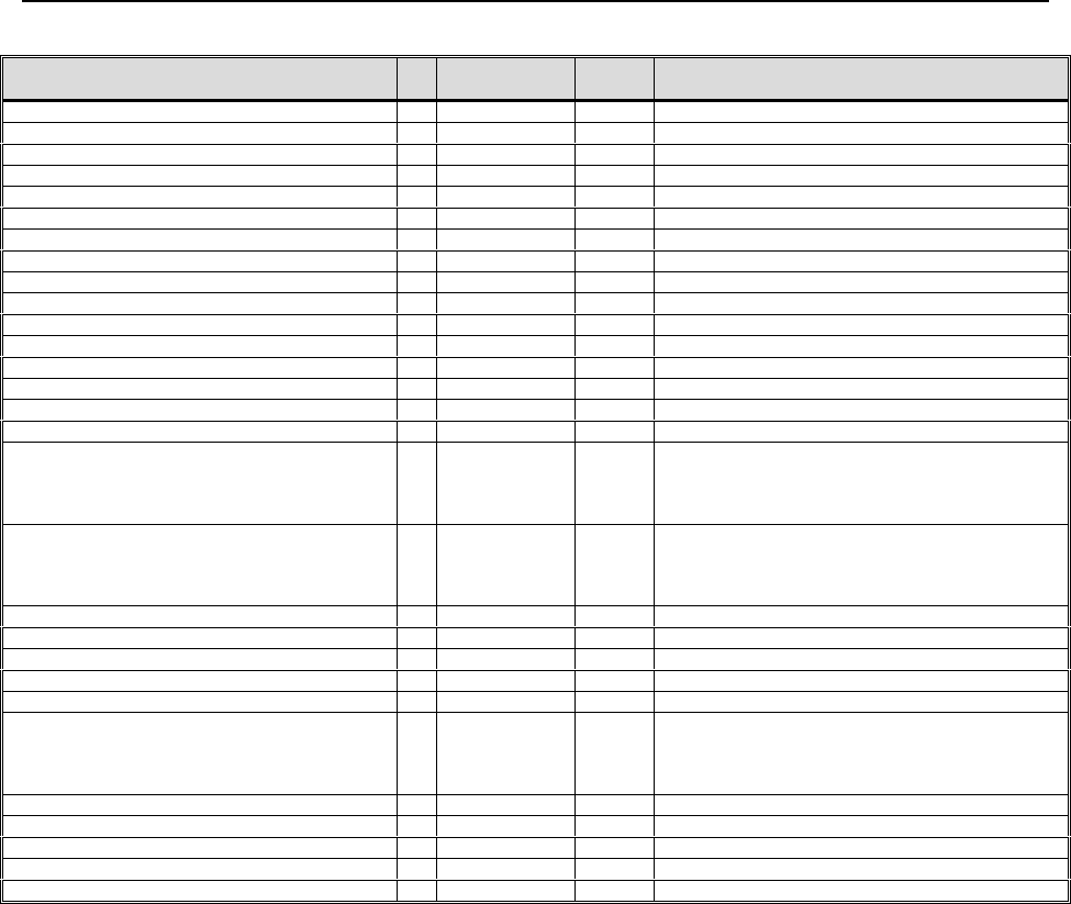
6.2.2 Initialization of TFM Parameters
Store into FLASH memory the hex values for TFM parameters listed in the following table or the nominal
value for 118 MHz (nominal values derived from trend data).
PTR for VHF-4000 and VDL-2000 Data Radios
______________________________________________________________________
______
©2000 Rockwell Collins, Inc Page 14 of 61
TFM Parameter #Applicable
Mode Value
(hex) Notes
I Phase Adjust 1 Tx 0000 normal setting for I phase adjustment DACs
Q Phase Adjust 2 Tx 2048 normal setting for Q phase adjustment DACs
Simulcomm 0 3 Rx FF sets SCOM Thresh DAC when Simulcomm discretes
= 00
Simulcomm 1 4 Rx FF sets SCOM Thresh DAC when Simulcomm discretes
= 01
Simulcomm 2 5 Rx FF sets SCOM Thresh DAC when Simulcomm discretes
= 10
Simulcomm 3 6 Rx FF sets SCOM Thresh DAC when Simulcomm discretes
= 11
Preselector 1 7 Rx/Tx 0000 sets Presel_1 DAC
Preselector 2 8 Rx/Tx 0000 sets Presel_2 DAC
Preselector 3 9 Rx/Tx 0000 sets Presel_3 DAC
Preselector 4 10 Rx/Tx 0000 sets Presel_4 DAC
PA Drive Bias for D8PSK 11 Rx/Tx 0000 sets PA Drive Bias DAC when in ARINC 750 Mode 2
PA Drive Bias for all but D8PSK 12 Rx/Tx 0000 sets PA Drive Bias DAC when not in ARINC 750
Mode 2
PA Final Bias for D8PSK 13 Rx/Tx 0000 sets PA Final Bias DAC when in ARINC 750 Mode 2
PA Final Bias for all but D8PSK 14 Rx/Tx 0000 sets PA Final Bias DAC when not in ARINC 750
Mode 2
D8PSK I Channel Gain 15 Tx 0000 sets I channel gain for D8PSK transmissions
D8PSK Q Channel Gain 16 Tx 0000 sets Q channel gain for D8PSK transmissions
AM I Channel Carrier Power 17 Tx 0000 sets I channel offset (carrier power) for AM
transmissions
AM Q Channel Carrier Power 18 Tx 0000 sets Q channel offset (carrier power) for AM
transmissions
D8PSK I Channel Carrier Null (offset) 19 Tx 0000 sets I channel offset (carrier null) for D8PSK
transmissions
D8PSK Q Channel Carrier Null (offset) 20 Tx 0000 sets Q channel offset (carrier null) for D8PSK
transmissions
Mode A I Channel Carrier Power
(offset) 21 Tx 0000 sets I channel offset (carrier power) for Mode A
transmissions
Mode A Q Channel Carrier Power
(offset) 22 Tx 0000 sets Q channel offset (carrier power) for Mode A
transmissions
AM I Channel Mod % (gain) 23 Tx 0000 Sets I channel mod % (gain) for AM Tx
AM Q Channel Mod % (gain) 24 Tx 0000 Sets Q channel mod % (gain) for AM transmissions
Mode A I Channel Mod % (gain) 25 Tx 0000 Sets I channel mod % (gain) for Mode A
transmissions
Mode A Q Channel Mod % (gain) 26 Tx 0000 Sets Q channel mod % (gain) for Mode A
transmissions
AM Voice Rx Audio Phase Shift 27 Rx 0000 Adjusts phase of Rx audio output relative to input RF
modulation
D8PSK Quadrature Mismatch 28 Tx 0000 compensates transmit signal for feedback modulator
mismatch
Rx Synthesizer Adjust 29 Rx 55 CN count for receiver synthesizer tuning
Tx Synthesizer Adjust 30 Tx 8C CN count for transmitter synthesizer tuning
I Low Voltage Phase Adjust 31 Tx 0000 normal setting for I phase adjustment DACs
Q Low Voltage Phase Adjust 32 Tx 07FF normal setting for Q phase adjustment DACs
Mode 2 –90.5 dBm Level 33 Rx normal setting for –90.5 dBm Mode 2 Rx level
Mode 2 –91.5 dBm Level 34 Rx normal setting for –91.5 dBm Mode 2 Rx level
AM I Channel Carrier Null (offset) 35 Tx 07FF sets I channel offset null for AM transmissions
AM Q Channel Carrier Null (offset) 36 Tx 07FF sets Q channel offset null for AM transmissions
Spur Suppression Noise Level 37 Tx 8.3 kHz synthesizer spur adj.
Spare 6 38 N/A
Spare 7 39 N/A
Spare 8 40 N/A
Spare 9 41 N/A
Spare 10 42 N/A
6.3 ALIGNMENT PROCEDURES
6.3.1 Receiver Analog Audio Output Level (VHF4000 Only) [Rx Cal]
1) Set Standard ARINC Configuration at 118.5 MHz.

PTR for VHF-4000 and VDL-2000 Data Radios
______________________________________________________________________
______
©2000 Rockwell Collins, Inc Page 15 of 61
2) Set Standard RF Generator Setting at 118.5 MHz.
3) Set Standard Discrete Configuration.
4) Set the generator to 85% modulation and -40 dBm RF level.
5) Monitor the receiver audio output and adjust calibration parameter #1 (Combined
audio level adjust) for 7.75 Vrms ± 0.1 Vrms.
6) Store the values used for calibration parameters #1, 2, and 40 in Flash memory.
6.3.2 Selcal Audio Output Level (VHF4000 Only) [Rx Cal]
1) Set Standard ARINC Configuration at current frequency.
2) Set Standard RF Generator setting at current frequency.
3) Set Standard Discrete Configuration.
4) Set the generator to 60% modulation and -40 dBm RF level.
5) Monitor the SELCAL audio output and adjust calibration parameter #40 (SELCAL
audio) for 500 mVrms ± 25 mVrms.
6) Store the values used for calibration parameters #1, 2, and 40 in Flash memory.
6.3.3 Voice Carrier Null [Tx TFM]
1) Set Standard ARINC Configuration at current frequency.
2) Set Standard Discrete Configuration.
3) Set the ARINC data to “Standard 25 kHz ARINC Configuration” on channel 118.500.
4) Connect 50 ohm load to antenna cable.
5) Ground the PTT (Pin 41), Monitor RF Transmitter power.
6) Simultaneously vary TFM parameters # 35 and # 36 (AM I and Q channel offset) to
get lowest possible power output. The null power out must be less than 4 dBm.
7) Unground the PTT.
6.3.4 Voice/Analog Data Bias Adjustment [Tx TFM]
1) Set Standard ARINC Configuration at current frequency.
2) Set Standard Discrete Configuration.
3) Set the ARINC data to “Standard 25 kHz ARINC Configuration” on channel 118.500.
4) Connect 50 ohm load to antenna cable.
5) Set TFM parameters #12 and #14 (PA drive bias and final driver bias) to $0000.
6) Ground the PTT (Pin 41), and monitor the input current to the UUT.
7) Adjust TFM parameter #14 until the current increases by 1500 ma ± 50 ma over the
original value.
8) Adjust TFM parameter #12 until the current increases by an additional 500 ma ± 50
ma over the value in step 8.
9) Unground the PTT.
10) Store the values used for TFM parameters #12 and #14 in the Flash memory
location for all temperature zones and channels.
11) Find values only at 118 MHz channel, use that value for all other channels.
6.3.5 +28 V Transmitter Phasing Adjustment [Tx TFM]
1) Set Standard ARINC Configuration at current frequency.
2) Set Standard Discrete Configuration.
3) Verify power supply input voltage is 27.5 +/- 0.2 Vdc.
4) Apply 0.7 Vrms, 1 kHz tone to Microphone Audio input.
5) Set I & Q channel carrier offset to 0
6) Set Q Channel Gain to 0.
7) Set I Channel Gain to get 4 – 6 watts RF output power
8) Monitor the Q_Detector Output of the RF Card

PTR for VHF-4000 and VDL-2000 Data Radios
______________________________________________________________________
______
©2000 Rockwell Collins, Inc Page 16 of 61
9) Ground the PTT and vary TFM parameter #1 & #2 (Q phase & I adjust) up or down
from initial value as necessary to null the Q detector voltmeter reading. Final value
must be less than TBD.
Note: The I& Q Phase Adjust values are calculated as a function of the phase angle
using the following formula:
Q bits = ((1.25 x sine (Angle) + 1.25)) / (2.5/4095)
I bits = ((1.25 x cos (Angle) + 1.25)) / (2.5/4095)
10) Unground the PTT.
11) Store the values for TFM parameter #1 and #2 in Flash memory.
6.3.6 +20 V Transmitter Phasing Adjustment [Tx TFM]
1) Set Standard ARINC Configuration at current frequency.
2) Set Standard Discrete Configuration.
3) Verify power supply input voltage is 20.0 +/- 0.2 Vdc.
4) Apply 0.7 Vrms, 1 kHz tone to Microphone Audio input.
5) Set I & Q channel carrier offset to 0
6) Set Q Channel Gain to 0.
7) Set I Channel Gain to get 4 – 6 watts RF output power
8) Monitor the Q_Detector Output of the RF Card
9) Ground the PTT and vary TFM parameter #30 & #31 (LV Q phase & I adjust) up or
down from initial value as necessary to null the Q detector voltmeter reading. Final
value must be less than TBD.
Note: The I& Q Phase Adjust values are calculated as a function of the phase angle
using the following formula:
Q bits = ((1.25 x sine (Angle) + 1.25)) / (2.5/4095)
I bits = ((1.25 x cos (Angle) + 1.25)) / (2.5/4095)
10) Unground the PTT.
11) Store the values for TFM parameter #1 and #2 in Flash memory.
6.3.7 Preselector Adjustments [Rx Cal]
1) Set Standard ARINC Configuration at current frequency.
2) Set Standard RF Generator setting at current frequency.
3) Set Standard Discrete Configuration.
4) Monitor the combined audio output.
5) Adjust the generator RF level to give approximately 12 dB SINAD ratio.
6) Iteratively adjust TFM parameters #7 –10 from initial values for the best SINAD while reducing the
RF level to maintain 12 dB SINAD. The final SINAD after adjustment must be at least 8 dB with –
103 dBm input RF level.
7) Store the values used for TFM parameters #7 - #10 in Flash memory.
6.3.8 Analog Voice/Data Unmodulated Transmitter RF Power [Tx TFM]
1) Set Standard ARINC Configuration at current frequency.
2) Set Standard Discrete Configuration.
3) Set TFM parameters #17 & #18 (AM I and Q channel carrier power) to 2048 (Dec).
4) Ground the PTT and increment TFM parameters # 17 until the RF wattmeter
indicates 10 watts +/- 1 watt.

PTR for VHF-4000 and VDL-2000 Data Radios
______________________________________________________________________
______
©2000 Rockwell Collins, Inc Page 17 of 61
5) Increment TFM parameters # 18 until the RF wattmeter indicates 19.5 watts +/- 1
watt.
6) Unground the PTT.
7) Store the values for TFM parameters #17 and 18 in Flash memory.
6.3.9 Simulcomm 0 Adjustment (-20 dBm threshold) [Rx TFM]
1) Set Standard ARINC Configuration at current frequency.
2) Set Standard RF Generator setting at current frequency.
3) Set Standard Discrete Configuration.
4) Set rear connector simulcomm discretes to 00 (VHF4000 Pins 42 and 46 open, VDL
Pins 16 and 34 open).
5) Set the generator RF level to -20 dBm and 90% modulation.
6) Monitor the AGC_Level output of the RF Card.
7) Decrease TFM parameter # 3 until the AGC_Level decreases at least 2% - 4% from
the reading in step 6.
8) Store the value used for TFM variable #3 in the Flash memory.
9) Find value at 118 MHz channel and use value for 119-125 MHz channels.
10) Find value at 126 MHz channel and use value for 127-136 MHz channels.
6.3.10 Simulcomm 1 Adjustment (-10 dBm threshold) [Rx TFM]
1) Set Standard ARINC Configuration at current frequency.
2) Set Standard RF Generator setting at current frequency.
3) Set Standard Discrete Configuration.
4) Set rear connector simulcomm discretes to 01(VHF4000 Pins 42 open and 46
ground, VDL Pins 16 open and 34 ground).
5) Set the generator RF level to -10 dBm and 90% modulation.
6) Monitor the AGC_Level output of the RF Card.
7) Decrease TFM parameter # 4 until the AGC_Level decreases at least 2% - 4% from
the reading in step 6.
8) Store the value used for TFM variable #4 in the Flash memory.
9) Find value at 118 MHz channel and use value for 119-125 MHz channels.
10) Find value at 126 MHz channel and use value for 127-136 MHz channels.
6.3.11 Analog Voice/Data Transmitter Modulation [Tx TFM]
1) Set Standard ARINC Configuration at current frequency.
2) Set Standard Discrete Configuration.
3) Apply a 0.4 Vrms audio signal at 1.0 kHz to the microphone input.
4) Ground the PTT and simultaneously increment TFM parameters #23 and 24 (AM I
and Q Channel Mod) to obtain modulation of the negative peaks at 90 +/- 3 %.
5) Unground the PTT.
6) Store the value used for TFM parameters #23 and #24 in the Flash memory.
6.3.12 Simulcomm 2 Adjustment ( 0 dBm threshold) [Rx TFM]
1) Set Standard ARINC Configuration at current frequency.
2) Set Standard RF Generator Setting at current frequency.
3) Set Standard Discrete Configuration.
4) Set rear connector simulcomm discretes to 10 (VHF4000 Pins 42 ground and 46
open, VDL Pins 16 open and 34 ground).
5) Set the generator RF level to 0 dBm and 90% modulation.
6) Monitor the AGC_Level output of the RF Card.

PTR for VHF-4000 and VDL-2000 Data Radios
______________________________________________________________________
______
©2000 Rockwell Collins, Inc Page 18 of 61
7) Decrease TFM parameter # 5 until the AGC_Level decreases at least 2% - 4% from
the reading in step 6.
8) Store the value used for TFM variable #5 in the Flash memory.
9) Find value at 118 MHz channel and use value for 119-125 MHz channels.
10) Find value at 126 MHz channel and use value for 127-136 MHz channels.
6.3.13 Analog and Digital Sidetone Levels [Tx Cal]
1) Set Standard ARINC Configuration at 126.500 MHz.
2) Set Standard Discrete Configuration.
3) Apply a 0.4 Vrms audio signal to the microphone input.
4) Ground the PTT and monitor the combined receiver audio output.
5) Adjust calibration parameter #13 (combined sidetone level adjust) for 3.87 ± 0.1
Vrms.
6) Unground the PTT.
7) Store the value calibration parameter # 12 and 13 in Flash memory.
6.3.14 Squelch Adjustment
6.3.14.1 25 KHZ NOISE QUIETING SQUELCH [RX CAL]
1) Set Standard ARINC Configuration at current frequency.
2) Set Standard RF Generator Setting at current frequency.
3) Set Standard Discrete Configuration.
4) Enable squelch on the ARINC tune word.
5) Set Cal Parameter #4 (Carrier Squelch Mute Threshold) to 4000.
6) Set Cal Parameter #5 (Carrier Squelch Unmute Threshold) to 0.
7) Set Cal Parameter #6 (25kHz Noise Squelch Mute Threshold) to 0.
8) Set Cal Parameter #7 (25kHz Noise Squelch Unmute Threshold) to 0.
9) Set Cal Parameter #6 (25kHz Noise Squelch Mute Threshold) to 4000.
10) Set the generator RF level to –103.5 dBm.
11) Monitor the receiver audio output.
12) Increase the value of calibration parameter #7 (25 kHz noise squelch unmute) from
$0000 until receiver audio is present (0.05 to 2.6 Vrms).
13) Reduce the RF generator output by 3 dB.
14) Decrease calibration parameter #6 (25 kHz noise squelch mute) from $03FF until the
receiver audio is muted (0.0 to 0.0245 Vrms).
15) Store the values for calibration parameters #6 and #7 in flash memory.
6.3.14.2 8.33 KHZ NOISE QUIETING SQUELCH [RX CAL]
1) Set Standard ARINC Configuration at current frequency.
2) Set Standard RF Generator Setting at current frequency.
3) Set Standard Discrete Configuration.
4) Enable squelch on the ARINC tune word.
5) Set Cal Parameter #4 (Carrier Squelch Mute Threshold) to 4000.
6) Set Cal Parameter #5 (Carrier Squelch Unmute Threshold) to 0.
7) Set Cal Parameter #8 (8.33kHz Noise Squelch Mute Threshold) to 0.
8) Set Cal Parameter #9 (8.33kHz Noise Squelch Unmute Threshold) to 0.
9) Set Cal Parameter #8 (8.33kHz Noise Squelch Mute Threshold) to 4000.
10) Set the generator RF level to -104 dBm.
11) Monitor the receiver audio output.
12) Increase value of calibration parameter #9 (8.33 kHz noise squelch unmute) from
$0000 until receiver audio is present (0.05 to 2.6 Vrms).

PTR for VHF-4000 and VDL-2000 Data Radios
______________________________________________________________________
______
©2000 Rockwell Collins, Inc Page 19 of 61
13) Reduce the RF generator output by 4 dB.
14) Decrease calibration parameter #8 (8.33 kHz noise squelch mute threshold) from
$03FF until the receiver audio is muted (0.0 to 0.049 Vrms).
15) Store the values for calibration parameters #8 and #9 in flash memory.
6.3.14.3 CARRIER SQUELCH
1) Set the UUT discrete inputs to “standard discrete configuration”.
2) Set the generator to 60% modulation by 6 kHz at –94.5 dBm.
3) Disable noise squelch by setting TFM #8 & #9 to $FFFF (Do not change values in FLASH)
4) Monitor the receiver audio output.
5) Increase value of calibration parameter #5 (carrier squelch unmute) from $0000 until receiver audio is
present (0.05 to 2.6 Vrms).
6) Reduce the RF generator output by 5 dB. Decrease calibration parameter #4 (carrier squelch mute) from
$FFFF until the receiver audio is muted (0.0 to 0.0245 Vrms).
8) Store the values for calibration parameters #4 and #5 in FLASH memory.
6.3.15 Mode A Alignment (Units/w Mode A Option Only)
6.3.15.1 MODE A RECEIVER
None
6.3.15.2 MODE A TRANSMITTER
Reserved
6.3.16 Mode 2 Alignment (Units/w Mode 2 Option Only)
6.3.16.1 MODE 2 BIAS ADJUSTMENT
1) Set the UUT discrete inputs to “standard discrete configuration”.
2) Set the ARINC data to “Standard 25 kHz ARINC Configuration” on channel 118.500.
3) Connect 50 ohm load to antenna cable
4) Set TFM parameters #18 and 19 (D8PSK I and Q channel offset) and #15 and 16 (D8PSK Channel
Gains) to $00 to set transmitter power to 0 watts.
5) Set TFM parameters #12 and #14 (PA drive bias and final driver bias) to $0000.
6) Ground the PTT (VHF-4000 pin 41, VDL-2000 pin 35), and monitor the input current to the UUT.
7) Adjust TFM parameter #12 until the current increases by 500 mA ± 50 mA over the original value.
8) Adjust TFM parameter #14 until the current increases by an additional 1500 mA ± 50 mA over the
value in step 5.
9) Unground the PTT.
10) Store the values used for TFM parameters #12 and #14 at 118.500 in 18 FLASH memory location up
to 136.500 MHz for the VDL-2000 and 151.5 MHz for the VHF-4000.
6.3.16.2 MODE 2 CARRIER NULL
1) Set the UUT discrete inputs to “standard discrete configuration”.
2) Tune the UUT to Channel 118.500.
3) Set TFM parameters # 15 and 16 (D8PSK I_Channel Gain and Q_Channel Gain) to $00.
4) Set TFM parameters # 18 and 19 to mid-scale: $800.
5) Ground the PTT line (Pin 41 VHF-4000, Pin 35 VDL-2000), and adjust TFMs # 18
and 19 (I_Offset and Q_Offset) alternately to null the carrier as detected on a
selective measuring receiver or power meter. The null shall be less than -15 dBm at
the sampled port.
6) Unground the PTT line.

PTR for VHF-4000 and VDL-2000 Data Radios
______________________________________________________________________
______
©2000 Rockwell Collins, Inc Page 20 of 61
7) Store the values used for TFM parameters #18 and #19 in FLASH memory.
Repeat for every 1 MHz step through 136.500 MHz using the previous band values as the initial values
6.3.16.3 MODE 2 RF POWER
1) Tune the UUT to Channel 118.500.
2) Set UUT to SSB mode
3) Set TFM parameters # 15 and 16 (D8PSK I_Channel Gain and Q_Channel Gain) to $00.
4) Increase the I_Mod TFM (#15) until 10.0 + 0.08 Watts is measured at the RF output and record value.
5) Set TFM parameters # 15 (D8PSK I_Channel Gain) to $00.
6) Increase the Q_Mod TFM (#16) until 10.0 + 0.08 Watts is measured at the RF output and record value.
7) Repeat for every 1 MHz step through 136.500 MHz.
8) Store the values used for TFM parameters #15 and #16 in FLASH memory.
6.3.16.4 D8PSK QUADRATURE MISMATCH
1) Tune the UUT to 118.5 MHz.
2) Set UUT to SSB mode
3) Ground the PTT line (Pin 41 VHF-4000, Pin 35 VDL-2000). Null the lower amplitude sideband of the
RF output by adjusting the D8PSK Quadrature Mismatch TFM (#28) while monitoring the output on a
spectrum analyzer. The lower amplitude sideband must be at least –40 dBc relative to the higher
amplitude sideband. The Q mod TFM (#16) determined in earlier adjustments may be adjusted as
required to aid in achieving the required null value of –45 dBc for the lower sideband.
4) Repeat for every 1 MHz step through 136.500 MHz using the previous band values as the initial values
for TFM #28.
5) Store the values used for TFM parameter #28 and #16 (if changed from initial value) in FLASH
memory.
6.3.17 Mode 2 AGC Calibration
8) Set Standard ARINC Configuration at 118.5 MHz.
9) Set Standard RF Generator setting at current frequency with CW signal at –90.5
dBm.
10) Set Standard Discrete Configuration.
11) Read receiver AGC value
12) Store this value in Flash memory for TFM parameter 33 (Mode 2 – 90.5 dBm level)
13) Readjust generator RF level for –91.5 dBm
14) Read receiver AGC value
15) Store this value in Flash memory for TFM parameter 34 (Mode 2- 91.5 dBm level)
16) Repeat for every 1 MHz step through 136.500 MHz
6.3.18 Flash Update
1) If not previously performed, write all TFMs that have been adjusted during previous alignment steps to
Flash Memory.
7. Final Test Requirements
Final Test may be performed manually or with the automatic alignment system (CATS-
21) executing DGS-005 or any combination thereof.
Unless otherwise specified, disable the squelch, connect a VHF signal generator to the
antenna input, and connect an audio distortion analyzer to the audio output (VHF-4000
combined audio pins 25 and 26, VDL-2000 RX_AUDIO_OUT pins 33 and 19).

PTR for VHF-4000 and VDL-2000 Data Radios
______________________________________________________________________
______
©2000 Rockwell Collins, Inc Page 21 of 61
NOTE: If necessary due to interference experienced during testing (and
as a result of the testing environment), a frequency on an adjacent
channel not more than 100 kHz away from the specified frequency
may be used for testing receive mode parameters.
7.1 POWER SUPPLIES
7.1.1 Current Drain at 27.5 Vdc
1) Set the UUT discrete inputs to “standard discrete configuration”.
2) Set the ARINC control data to “Standard 25 kHz ARINC Configuration” on channel 128.500.
3) Set the input voltage to 27.5 Vdc.
4) Measure the DC input current.
Production Limit: 0.43 +/- 0.4 amp
Abort Test Limit: > 0.55 amp
7.1.2 Current Drain at 18.0 Vdc
1) Decrease the input voltage to 18.0 ± 0.5 Vdc and measure the input current.
Production Limit: 0.8 +/- 0.3 amp
7.1.3 Internal Power Supplies
1) Reset the input voltage to 27.5 +/- 0.6 Vdc.
2) Measure the outputs of the following internal supplies using the 353 label:
a) +3.3 Volt Supply Production Limit: +3.3 Vdc to 3.55 Vdc
b) +8.0 Volt Supply Production Limit: +7.3 Vdc to 8.90 Vdc
c) +15.0 Volt Supply Production Limit: +14.5 Vdc to 17.5 Vdc
7.2 VOICE/ANALOG DATA MODE TESTS
7.2.1 Voice/Analog Data Receiver Tests
7.2.1.1 SIMULCOMM
1.2.1.1.1. -20 DBM THRESHOLD
1) Set Standard ARINC Configuration at 112.00 MHz.
2) Set Standard Discrete Configuration.
3) Set rear connector simulcomm discretes to 00 (VHF4000 Pins 42 and 46 open, VDL
Pins 16 and 34 open).
4) Set the generator RF level to -50 dBm and 90% modulation, 1 kHz Tone.
5) Monitor the AGC_Level output of the RF Card or the Label 353 AGC Level
6) Increase the RF level in 1 dB steps
7) Verify the RF level required to cause a 2% change in AGC Level.
8) Repeat steps 4 through 6 for channel 132.000 MHz
Production Limit: -20 dBm +/- 10 dBm
1.2.1.1.1. -10 DBM THRESHOLD
1) Set Standard ARINC Configuration at 112.00 MHz.

PTR for VHF-4000 and VDL-2000 Data Radios
______________________________________________________________________
______
©2000 Rockwell Collins, Inc Page 22 of 61
2) Set Standard Discrete Configuration.
3) Set rear connector simulcomm discretes to 01(VHF4000 Pins 42 open and 46
ground, VDL Pins 16 open and 34 ground).
4) Set the generator RF level to -50 dBm and 90% modulation, 1 kHz Tone.
5) Monitor the AGC_Level output of the RF Card or the Label 353 AGC Level
6) Increase the RF level in 1 dB steps
7) Verify the RF level required to cause a 2% change in AGC Level.
8) Repeat steps 4 through 6 for channel 132.000 MHz
Production Limit: -10 dBm +/- 10 dBm
1.2.1.1.1. 0 DBM THRESHOLD
1) Set Standard ARINC Configuration at 112.00 MHz.
2) Set Standard Discrete Configuration.
3) Set rear connector simulcomm discretes to 10 (VHF4000 Pins 42 ground and 46
open, VDL Pins 16 open and 34 ground).
4) Set the generator RF level to -50 dBm and 90% modulation, 1 kHz Tone.
5) Monitor the AGC_Level output of the RF Card or the Label 353 AGC Level
6) Increase the RF level in 1 dB steps
7) Verify the RF level required to cause a 2% change in AGC Level.
8) Repeat steps 4 through 6 for channel 132.000 MHz
Production Limit: 0 dBm +/- 10 dBm
7.2.1.2 SENSITIVITY
1.2.2.1.1. SENSITIVITY 25 KHZ MODE CHANNEL 118.000 (BAND 1 LOW SIDE)
1) Set the UUT discrete inputs to “standard discrete configuration”.
2) Set the RF Generator to “standard RF generator configuration” at 118.000 MHz.
3) Disable squelch
4) Set the ARINC control data to “Standard 25 kHz ARINC Configuration” on channel 118.000 MHz.
5) Set the RF generator output level to –103.5 dBm.
6) Verify the S+N/N ratio at the combined audio output
Production Limit: 14.25 +/- 5.75 dB
1.2.2.1.1. SENSITIVITY 25 KHZ MODE CHANNEL 118.975 (BAND 1 HIGH SIDE)
1) Set the ARINC control data to channel 118.975.
2) Set the RF Generator to “standard RF generator configuration” at 118.975.
3) Verify the S+N/N ratio at the combined audio output.
Production Limit: 14.25 +/- 5.75 dB
1.2.2.1.1. SENSITIVITY 25 KHZ MODE CHANNEL 119.500 THROUGH 135.500
(BANDS 2 – 17 CENTERS)
1) Set the RF Generator frequency to 119.550, 120.550, 121.550, …, 135.550 MHz.
2) Set the ARINC control data to channel to 119.550, 120.550, 121.550, …, 135.550 MHz.
3) Verify the S+N/N ratio at the combined audio output.

PTR for VHF-4000 and VDL-2000 Data Radios
______________________________________________________________________
______
©2000 Rockwell Collins, Inc Page 23 of 61
Production Limit: 14.25 +/- 5.75 dB
1.2.2.1.1. SENSITIVITY 25 KHZ MODE CHANNEL 136.000 (BAND 18 LOW SIDE)
1) Set the RF Generator frequency to 136.000 MHz.
2) Set the ARINC control data to channel 136.000.
3) Verify the S+N/N ratio at the combined audio output.
Production Limit: 14.25 +/- 5.75 dB
1.2.2.1.1. SENSITIVITY 25 KHZ MODE CHANNEL 136.975 (BAND 18 HIGH
SIDE)
1) Set the RF Generator frequency to 136.975 MHz.
2) Set the ARINC control data to channel 136.975.
3) Verify the S+N/N ratio at the combined audio output.
Production Limit: 14.25 +/- 5.75 dB
1.2.2.1.1. SENSITIVITY 25 KHZ MODE CHANNEL 144.450 (VHF-4000 WITH
EXTENDED RANGE OPTION ONLY)
1) Set the RF Generator frequency to 144.450 MHz.
2) Set the ARINC control data to channel 144.450.
3) Verify the S+N/N ratio at the combined audio output.
Production Limit: 14.25 +/- 5.75 dB
1.2.2.1.1. SENSITIVITY 25 KHZ MODE CHANNEL 151.000 (VHF-4000 ONLY,
BAND 33 LOW SIDE)
1) Set the RF Generator frequency to 151.000 MHz.
2) Set the ARINC control data to channel 151.000.
3) Verify the S+N/N ratio at the combined audio output.
Production Limit: 14.25 +/- 5.75 dB
1.2.2.1.1. SENSITIVITY 25 KHZ MODE CHANNEL 151.975 (VHF-4000 ONLY,
BAND 33 HIGH SIDE)
1) Set the RF Generator frequency to 151.975 MHz.
2) Set the ARINC control data to channel 151.975.
3) Verify the S+N/N ratio at the combined audio output.
Production Limit: 14.25 +/- 5.75 dB

PTR for VHF-4000 and VDL-2000 Data Radios
______________________________________________________________________
______
©2000 Rockwell Collins, Inc Page 24 of 61
1.2.2.1.1. SENSITIVITY 8.3 KHZ MODE CHANNEL 126.005
1) Set the RF Generator frequency to 126.000 MHz.
2) Set the ARINC control data to “Standard 8.33 kHz ARINC Configuration” on channel 126.005.
3) Verify the S+N/N ratio at the combined audio output.
Production Limit: 14.25 +/- 5.75 dB
7.2.1.3 SENSITIVITY DURING LOW LINE VOLTAGE [ENTRY]
1.2.3.1.1. SENSITIVITY DURING LOW LINE VOLTAGE CHANNEL 118.000
1) Set the UUT power input for +18 ± 0.2 Vdc.
2) Set the UUT discrete inputs to “standard discrete configuration”.
3) Set the RF Generator to “standard RF generator configuration” at 118.000 MHz.
4) Set the ARINC control data to “Standard 25 kHz ARINC Configuration” on channel 118.000 MHz.
5) Set the RF generator output level to –103.5 dBm.
6) Verify the S+N/N ratio at the combined audio output.
Production Limit: >= 8.5 dB
1.2.3.1.1. SENSITIVITY DURING LOW LINE VOLTAGE CHANNEL 136.975
1) Set the RF Generator frequency to 136.975 MHz.
2) Set the ARINC control data to channel 136.975.
3) Verify the S+N/N ratio at the combined audio output.
4) Reset the UUT power input to +27.5 ± 0.1 Vdc.
Production Limit: >= 8.5 dB
7.2.1.4 RECEIVER QUIETING
1) Set the RF generator to “standard RF generator configuration” at 126.000 MHz.
2) Set the ARINC control data to channel 126.000.
3) Set the RF generator output level to -53 dBm.
4) Establish a 0 dB reference for the combined audio output level.
5) Remove the modulation from the RF generator.
6) Verify the change in the level of the combined audio output signal.
Production Limit: >= 45 dB
7.2.1.5 IMAGE REJECTION
1) Channel the receiver to 135.975 MHz.
2) Set the RF Generator to “standard RF generator configuration” at 135.975 MHz.
3) Record the RSSI level for an input of –103.5 dBm.
4) Set the RF Generator to 193.725 MHz.
5) Increase the level out of the RF Generator until the RSSI level is the same as obtained in step 3.
Production Limit: >= 60 dB

PTR for VHF-4000 and VDL-2000 Data Radios
______________________________________________________________________
______
©2000 Rockwell Collins, Inc Page 25 of 61
7.2.1.6 SQUELCH OPERATION
1.2.6.1.1. 25 KHZ NOISE SQUELCH OPERATION
7.2.1.6.0.1 25 kHz Noise Squelch Closure
1) Set the UUT discrete inputs to “standard discrete configuration”.
2) Set the RF Generator to “standard RF generator configuration” at 126.600 MHz.
3) Set the ARINC control data to “Standard 25 kHz ARINC Configuration” on channel 126.600.
4) Set the RF Generator output level to –115 dBm.
5) Verify the combined audio output.
Production Limit: <= 0.1 Vrms
7.2.1.6.0.2 25 kHz Noise Squelch Opening RF Level
1) Increase the RF generator output level until the audio out is > 3.0 Vrms.
2) Verify the noise squelch opening RF level
3) Record the RF level as Refsq.
Production Limit: -103.5 +/- 2 dB
7.2.1.6.0.3 25 kHz Noise Squelch RF Level Change for Closure
1) Decrease the RF generator output level until the audio out is < 1.0 Vrms.
2) Verify the change in RF level from Refsq to obtain noise squelch closure.
Production Limit: -4 +/- 2 dB
7.2.1.6.0.4 8.33 kHz Noise Squelch Closed at –115 dBm
1) Set the UUT discrete inputs to “standard discrete configuration”.
2) Set the RF Generator to “standard RF generator configuration” at 126.600 MHz.
3) Set the ARINC control data to “Standard 8.33 kHz ARINC Configuration” on channel 126.605.
4) Set the RF Generator output level to –115 dBm.
5) Verify the combined audio output.
Production Limit: <= 0.1 Vrms
7.2.1.6.0.5 8.33 kHz Noise Squelch Opening RF Level
1) Increase the RF generator output level until the audio out is > 3.0 Vrms.
2) Verify the noise squelch opening RF level
3) Record the RF level as Ref.
Production Limit: -103.5 +/- 2 dB
7.2.1.6.0.6 8.33 kHz Noise Squelch RF Level Change for Closure
1) Decrease the RF generator output level until the audio out is < 1.0 Vrms.
2) Verify the change in RF level from Ref. to obtain noise squelch closure.
Production Limit: -4 +/- 2 dB

PTR for VHF-4000 and VDL-2000 Data Radios
______________________________________________________________________
______
©2000 Rockwell Collins, Inc Page 26 of 61
1.2.6.1.1. CARRIER SQUELCH OPERATION
7.2.1.6.1.1 Carrier Squelch Open
1) Set the UUT discrete inputs to “standard discrete configuration”.
2) Set the RF Generator to “standard RF generator configuration” at 126.600 MHz.
3) Set the ARINC control data to “Standard 25 kHz ARINC Configuration” on channel 126.600.
4) Set the RF generator for simultaneous modulation with a 6 kHz sine wave at 60% AM and a 1 kHz
sine wave at 30% AM at an RF level of -105 dBm.
5) Slowly increase the RF level (approx. 1 dB per 2 sec) until the audio out is > 5.0 Vrms.
6) Verify the carrier squelch opening RF level.
7) Record the RF level as Refsq2.
Production Limit: -94.5 +/- 4.5 dBm
7.2.1.6.1.2 Carrier Squelch Closure
1) Slowly decrease the RF level (approx. -1 dB per 2 sec) until the audio out is < 5.0 Vrms.
2) Verify the change in RF level from Refsq2 to obtain carrier squelch closure.
Production Limit: -5.0 +/- 2.5 dB
7.2.1.7 AGC CHARACTERISTICS
1) Set the UUT discrete inputs to “standard discrete configuration”.
2) Set the RF Generator to “standard RF generator configuration” at 126.600 MHz and -50 dBm.
3) Set the ARINC control data to “Standard 25 kHz ARINC Configuration” on channel 126.600.
4) Establish a 0 dB reference RefAGC
.
1.2.7.1.1. AGC TRACKING @ 0 DBM
1) Set the RF generator output level to 0 dBm.
2) Verify the change in audio output level from RefAGC
in dB.
Production Limit: <= 3 dB
1.2.7.1.1. AGC TRACKING @ -10 DBM
1) Set the RF generator output level to -10 dBm.
2) Verify the change in audio output level from RefAGC
in dB.
Production Limit: <= 3 dB
1.2.7.1.1. AGC TRACKING @ -20 DBM
1) Set the RF generator output level to -20 dBm.
2) Verify the change in audio output level from RefAGC
in dB.
Production Limit: <= 3 dB
1.2.7.1.1. AGC TRACKING @ -30 DBM
1) Set the RF generator output level to -30 dBm.
2) Verify the change in audio output level from RefAGC
in dB.
Production Limit: <= 3 dB
1.2.7.1.1. AGC TRACKING @ -40 DBM
1) Set the RF generator output level to -40 dBm.
2) Verify the change in audio output level from RefAGC
in dB.

PTR for VHF-4000 and VDL-2000 Data Radios
______________________________________________________________________
______
©2000 Rockwell Collins, Inc Page 27 of 61
Production Limit: <= 3 dB
1.2.7.1.1. AGC TRACKING @ -60 DBM
1) Set the RF generator output level to -60 dBm.
2) Verify the change in audio output level from RefAGC
in dB.
Production Limit: <= 3 dB
1.2.7.1.1. AGC TRACKING @ -70 DBM
1) Set the RF generator output level to -70 dBm.
2) Verify the change in audio output level from RefAGC
in dB.
Production Limit: <= 3 dB
1.2.7.1.1. AGC TRACKING @ -80 DBM
1) Set the RF generator output level to -80 dBm.
2) Verify the change in audio output level from RefAGC
in dB.
Production Limit: <= 3 dB
1.2.7.1.1. AGC TRACKING @ -90 DBM
1) Set the RF generator output level to -90 dBm.
2) Verify the change in audio output level from RefAGC
in dB.
Production Limit: <= 3 dB
1.2.7.1.1. AGC TRACKING @ -104 DBM
1) Set the RF generator output level to -104 dBm.
2) Verify the change in audio output level from RefAGC
in dB.
Production Limit: <= 4 dB
7.2.1.8 VOICE AUDIO OUTPUT
1.2.8.1.1. COMBINED AUDIO OUTPUT LEVEL
1) For the VHF-4000 only.
2) Set the UUT discrete inputs to “standard discrete configuration”.
3) Set the RF Generator to -54 dBm output level at 126.600 MHz, modulated 80% by a 1 kHz sine wave.
4) Set the ARINC control data to “Standard 25 kHz ARINC Configuration” on channel 126.600.
5) Verify the analog audio output level at the combined audio output (VHF4000 pins 25 and 26).
Production Limit: 7.75 +/- 0.2 Vrms
1.2.8.1.1. RECEIVED AUDIO OUTPUT LEVEL
1) Set the UUT discrete inputs to “standard discrete configuration”.
2) Set the RF Generator to -54 dBm output level at 126.600 MHz, modulated 80% by a 1 kHz sine wave.
3) Set the ARINC control data to “Standard 25 kHz ARINC Configuration” on channel 126.600.
4) Verify the analog audio output level at the received audio output (VHF-4000 pins 19 and 26, VDL-
2000 pins 33 and 19).
Production Limit: 7.75 +/- 0.2 Vrms
1.2.8.1.1. AUDIO OUTPUT PHASING

PTR for VHF-4000 and VDL-2000 Data Radios
______________________________________________________________________
______
©2000 Rockwell Collins, Inc Page 28 of 61
1) Set the UUT discrete inputs to “standard discrete configuration”.
2) 2) Apply a -54 dBm signal at 126.600 MHz, modulated 30% at 1 kHz.
3) Set the ARINC control data to “Standard 25 kHz ARINC Configuration” on channel
126.600.
4) Verify that the phase of the received combined audio output signal with respect to the envelope of the
RF input signal is within ± 20 degrees.
Production Limit: Audio output to envelope phase shift: < ± 20
degrees at 1000 Hz.
CMM Limit: N/A
1.2.8.1.1. AUDIO FREQUENCY RESPONSE
1) Set the UUT discrete inputs to “standard discrete configuration”.
2) Set the RF Generator to “standard RF generator configuration” at 126.600 MHz.
3) Set the ARINC control data to “Standard 25 kHz ARINC Configuration”.
4) Apply a –54 dBm signal at 126.600 MHz, modulated 30% at 1 kHz.
5) Adjust the distortion analyzer connected to the combined audio output (pins 25 and
26) to establish a 0 dB reference.
6) Change the modulating frequency to 300 Hz and verify the change in level in dB of
the audio output
Production Limit: <= 6 dB variation 300 to 2500 Hz
CMM Limit: <= 6 dB variation 300 to 2500 Hz
7) Change the modulating frequency to 4000 Hz and verify the change in level in dB of
the audio output
Production Limit: >= 42 dB attenuation at 4 kHz.
CMM Limit: >= 18 dB attenuation at 4 kHz

PTR for VHF-4000 and VDL-2000 Data Radios
______________________________________________________________________
______
©2000 Rockwell Collins, Inc Page 29 of 61
1.2.8.1.1. AUDIO OUTPUT DISTORTION
1) Set the UUT discrete inputs to “standard discrete configuration”.
2) Apply a –54 dBm signal at 126.600 MHz, modulated 80% at 1 kHz.
3) Set the ARINC control data to “Standard 25 kHz ARINC Configuration” on channel 126.600.
4) Adjust the distortion analyzer connected to the combined audio output (VHF-4000 pins 25 and 26,
VDL-2000 pins 33 and 19 ) and measure audio distortion.
Production Limit: Audio distortion: <= 5%
CMM Limit: Audio distortion: <= 7%
1.2.8.1.1. RX AUDIO COMPRESSOR
1) Set the UUT discrete inputs to “standard discrete configuration”.
2) Apply a –54 dBm signal at 126.600 MHz, modulated 50% at 1 kHz.
3) Set the ARINC control data to “Standard 25 kHz ARINC Configuration” on channel 126.600.
4) Verify the audio output level.
5) Increase the modulation depth to 90% and note that the change in combined audio output level.
Production Limit: Audio variation: <= 1 dB.
CMM Limit: Audio variation: >= 3 dB.
7.2.1.9 SELCAL AUDIO OUTPUT (VHF-4000 ONLY)
1.2.9.1.1. OUTPUT LEVEL
1) Set the UUT discrete inputs to “standard discrete configuration”.
2) Set the RF Generator to “standard RF generator configuration” at 126.600 MHz.
3) Set the ARINC control data to “Standard 25 kHz ARINC Configuration”.
4) Apply -54 dBm signal at 126.600 MHz, modulated 60% at 1 kHz to the antenna port.
5) Verify the SELCAL audio output level at the combined audio output (pins 38 and 37)
Production Limit: SELCAL audio output: 1.0 +/- .2 Vrms
CMM Limit: SELCAL output level: 1.0 - .3 Vrms

PTR for VHF-4000 and VDL-2000 Data Radios
______________________________________________________________________
______
©2000 Rockwell Collins, Inc Page 30 of 61
1.2.9.1.1. SELCAL AUDIO FREQUENCY RESPONSE (VHF4000 ONLY)
1) Apply a –54 dBm signal at 126.600 MHz, modulated 60% at 1 kHz.
2) Adjust the audio distortion analyzer connected to the combined SELCAL output to establish a 0 dB
reference.
3) Set the modulating frequency to 300 Hz and verify the change in level of the audio output from the
reference value
Production Limit: <= 6 dB variation 300 to 1000 Hz
CMM Limit: <= 6 dB variation 300 to 1000 Hz
4) Set the modulating frequency to 6600 Hz and verify the change in level of the audio output from the
reference value
Production Limit: <= 6 dB variation 1000 to 6600 HZ
CMM Limit: <= 6 dB variation 1000 to 6600 Hz
1.2.9.1.1. SELCAL AUDIO OUTPUT DISTORTION (VHF4000 ONLY)
1) Set UUT to ARINC 716 voice mode.
2) Apply a –54 dBm signal at 126.600 MHz, modulated 80% at 1 kHz.
3) Adjust the distortion analyzer connected to the SELCAL audio output and measure audio distortion.
Production Limit: Audio distortion: <= 5%
CMM Limit: Audio distortion: <= 7%
Receiver Compressor OK
7.2.2 Voice/Analog Data Mode Transmitter Tests
Unless otherwise specified, the tests are to be performed at 126.500 MHz. Always keep
the antenna port connected to a 50 ohm load.

PTR for VHF-4000 and VDL-2000 Data Radios
______________________________________________________________________
______
©2000 Rockwell Collins, Inc Page 31 of 61
7.2.2.1 UNMODULATED RF POWER OUTPUT/CURRENT
1) Set the UUT discrete inputs to “standard discrete configuration”.
2) Set the ARINC control data to “Standard 25 kHz ARINC Configuration”.
3) Tune the UUT to Channel 118.500.
4) Ground the PTT line (Pin 41 VHF-4000, Pin 35 VDL-2000 ), measure and verify the output power and
input current
5) Unground the PTT line.
6) For the VHF-4000 repeat for every 1 MHz step through 136.500 MHz.
7) For the VDL-2000 repeat for every 1 MHz step through 136.500 MHz.
Production Limit: 18-21 watts
Production Limit: <= 5.5 amps
CMM Limit: >= 16 watts
CMM Limit: <= 5.5 amps
7.2.2.2 POWER OUTPUT DURING LOW LINE VOLTAGE
1) Set the UUT power input for +18 +/- 0.2 Vdc.
2) AC couple an audio oscillator to the mic audio input hi and low (Pins 54 and 66 for VHF-4000, Pins 4
and 30 for VDL-2000).
3) Set audio oscillator frequency to 1kHz with amplitude of +1 Vrms.
4) Verify the total RF output power including modulation sidebands at 126.500 MHz.
5) Set input line voltage to 27.5 Vdc.
Production Limit: >= 8 watts.
CMM Limit: >= 6 watts.
7.2.2.3 TX COMPRESSOR
1.2.3.2.1. ANALOG INPUT COMPRESSOR THRESHOLD
1) Set the UUT discrete inputs to “standard discrete configuration”.
2) Set the ARINC control data to “Standard 25 kHz ARINC Configuration”.
3) Tune UUT to 126.500 MHz.
4) Connect the RF output to an AM modulation analyzer through a 40 dB pad.
5) AC coupled the output of the audio analyzer to the mic audio input hi and low (Pins 54 and 66 for
VHF-4000, Pins 4 and 30 for VDL-2000).
6) Set the audio analyzer frequency to 1 kHz with amplitude of zero volts.
7) Ground the PTT line and increase the mic audio (1 kHz) from 0 volts until the negative modulation
stops increasing.
8) Unground the PTT line.
9) Verify the audio input voltage (Note: The actual input voltage is a factor of 4 less than the output
voltage displayed by the audio analyzer due to the impedance mismatch).
Production Limit: 0.1 to 0.15 Vrms
CMM Limit: 0.08 to 0.175 Vrms
1.2.3.2.1. ANALOG INPUT COMPRESSOR RANGE
1) Tune UUT to 126.500 MHz.
2) Ground the PTT and increase the mic audio voltage to 1.25 Vrms.

PTR for VHF-4000 and VDL-2000 Data Radios
______________________________________________________________________
______
©2000 Rockwell Collins, Inc Page 32 of 61
3) Verify the percentage of negative modulation. Unkey the PTT line.
Production Limit: >= 83% but LT 100%.
CMM Limit: >= 70% but LT 100%.
7.2.2.4 25 KHZ TRANSMITTER MODULATION DISTORTION (25 KHZ MODE)
1) Set the UUT discrete inputs to “standard discrete configuration”.
2) Set the ARINC control data to “Standard 25 kHz ARINC Configuration”.
3) Tune UUT to 126.500 MHz.
4) Apply an audio input of 0.5 Vrms at 1 kHz at mic input.
5) Ground the PTT line and measure the demodulated RF distortion
6) Unground the PTT line.
7) Repeat steps 2-4 using 350 and 2500, and 6600 Hz.
Production Limit: <= 7% distortion.
CMM Limit: <= 10% distortion.
7.2.2.5 25 KHZ VOICE AUDIO FREQUENCY RESPONSE (25 KHZ MODE)
1) Set the UUT discrete inputs to “standard discrete configuration”.
2) Set the ARINC control data to “Standard 25 kHz ARINC Configuration”.
3) Tune unit to 126.500 MHz
4) Apply a 0.5 Vrms audio signal to the mic audio input.
5) While the PTT line is grounded, measure the variation in dB of the audio out of the modulation meter
as the audio input frequency is set to 300, 1000, and 6600 Hz.
6) Unground the PTT line.
Production Limit: <= 4 dB variation.
CMM Limit: <= 6 dB variation.
7.2.2.6 8.33 KHZ TRANSMITTER MODULATION DISTORTION (8.33 KHZ MODE)
1) Tune UUT to channel 126.430 MHz.
2) Apply an audio input of 0.5 Vrms at 1 kHz to the mic input.
3) Ground the PTT line and measure the demodulated RF distortion
4) Unground the PTT line.
5) Repeat steps 2-4 using 350 and 2500 Hz
Production Limit: <= 5% distortion.
CMM Limit: <= 7% distortion.
7.2.2.7 8.33 KHZ VOICE AUDIO FREQUENCY RESPONSE (8.33 KHZ MODE)
1) Tune unit to channel 126.430 MHz
2) Apply a 0.5 Vrms audio signal to the mic audio input.
3) Connect a distortion analyzer to the modulation output of the modulation meter.
4) While the PTT line is grounded, measure the variation in dB of the audio out of the modulation meter
with the audio input frequency set to 300, 1000, 2500, and 3200 Hz.
5) Unground the PTT line.

PTR for VHF-4000 and VDL-2000 Data Radios
______________________________________________________________________
______
©2000 Rockwell Collins, Inc Page 33 of 61
Production Limit: <= 6 dB variation 300 to 2500 Hz, –30 dB or
less at 3200 Hz
CMM Limit: <= 6 dB variation 300 to 2500 Hz, –30 dB or
less at 3200 Hz
7.2.2.8 MICROPHONE BIAS
1) Set the UUT discrete inputs to “standard discrete configuration”.
2) Set the ARINC control data to “Standard 25 kHz ARINC Configuration”.
3) With no audio applied, ground the PTT line and measure open circuit voltage at mic audio input hi
(Pin 54 VHF-4000, Pin 4 VDL-2000).
4) Unground the PTT line.
Production Limit: 16.0 ± 1.5 Vdc.
CMM Limit: 16.0 ± 1.5 Vdc.
7.2.2.9 SIDETONE
1.2.9.2.1. SIDETONE FREQUENCY RESPONSE
1) Set the UUT discrete inputs to “standard discrete configuration”.
2) Set the ARINC control data to “Standard 25 kHz ARINC Configuration”.
3) Tune UUT to 126.500 MHz.
4) Connect the combined audio out (pins 25 and 26 VHF-4000, pins 31 and 19 VDL-2000) to the
distortion analyzer.
5) Apply 0.125 Vrms at 1 kHz signal to the mic audio input
6) Ground the PTT line.
7) Obtain a 0 dB reference on the audio analyzer.
8) Set the modulating frequency to 300, 1000, and 2500 Hz, verify the change in the audio out level
measured on the audio analyzer.
9) Unground the PTT line.
Production Limit: <= 6 dB.
CMM Limit: <= 6 dB.
1.2.9.2.1. SIDETONE DISTORTION
1) Tune UUT to 126.500 MHz.
2) Connect the Sidetone audio out (pins 20 and 26 VHF-4000, pins 31 and 19 VDL-2000) to the
distortion analyzer.
3) Apply 0.25 Vrms at 1 kHz to the mic audio input
4) Ground the PTT line.
5) Measure and verify the audio output distortion
6) Repeat using 300, 1000, and 2500 Hz at mic audio input.
7) Unground PTT
Production Limit: <= 7%.
CMM Limit: <= 10%.

PTR for VHF-4000 and VDL-2000 Data Radios
______________________________________________________________________
______
©2000 Rockwell Collins, Inc Page 34 of 61
1.2.9.2.1. SIDETONE LEVEL AND SIDETONE SWITCHING
1) Tune UUT to 126.500 MHz.
2) Connect the Sidetone audio output (pins 20 and 26 VHF-4000, pins 31 and 19 VDL-2000) to the audio
analyzer.
3) Apply 0.25 Vrms at 1 kHz to the mic audio input
4) Ground the PTT line.
5) Measure the audio level at Sidetone audio output.
6) Unground the PTT.
7) Apply a –54 dBm RF signal at 1 kHz, 30 % at 126.500 MHz to RF input
8) Measure the audio level at sidetone output.
Production Limit: 3.87 +/- 0.2 Vrms
CMM Limit: 3.87 +/- 0.3 Vrms
Production Limit: <= 0.1 Vrms
CMM Limit: <= 0.1 Vrms
7.2.2.10 TRANSMIT CARRIER NOISE LEVEL
1) Set the UUT discrete inputs to “standard discrete configuration”.
2) Set the ARINC control data to “Standard 25 kHz ARINC Configuration”.
3) Apply a 1 kHz audio signal to the mic audio input.
4) Connect the modulation analyzer to the antenna port.
5) Ground the PTT line.
6) Establish a 0 dB reference on the distortion analyzer.
7) Remove the modulation and verify the change in level of the modulation meter’s modulation output.
(Use 300 Hz - 3 kHz filtering on the modulation meter and disable any auto ranging function
8) Unground PTT line.
Production Limit: >= 43 dB.
CMM Limit: > 35 dB.
7.2.2.11 8.33 KHZ SPECTRUM TEST (PERFORM ON A SAMPLE BASIS ONLY!)
1) Set the UUT discrete inputs to “standard discrete configuration”.
2) Set the ARINC control data to “Standard 8.33 kHz ARINC Configuration”.
3) Set UUT to Channel 126.430.
4) Apply an 800 Hz, 0.125 Vrms audio signal to the mic audio input.
5) Ground the PTT line and adjust level of audio signal so as to achieve 80 +/- 2% modulation on
combined positive and negative peaks.
6) With a spectrum analyzer connected so as to measure the RF output, measure level of modulation
sidebands at +/- 3200 Hz relative to the carrier level.
7) Unground the PTT line.
Production Limit: >= 50 dB.
CMM Limit: N/A.

PTR for VHF-4000 and VDL-2000 Data Radios
______________________________________________________________________
______
©2000 Rockwell Collins, Inc Page 35 of 61
7.2.2.12 3:1 VSWR TEST (PERFORM ON A SAMPLE BASIS ONLY!)
1) Set the UUT discrete inputs to “standard discrete configuration”.
2) Set the ARINC control data to “Standard 25 kHz ARINC Configuration”.
3) Tune the UUT to channel 118.500.
4) Apply 1.0 Vrms at 1 kHz to the mic audio input.
5) Connect UUT to 3:1 VSWR simulator
8) Ground the PTT line while monitoring RF envelope with oscilloscope connected to test port on 3:1
VSWR simulator
9) Rotate VSWR simulator through all phase angles and verify that no oscillators are present
10) Unground the PTT line.
11) For the VHF-4000 repeat for every 1 MHz step through 136.5 MHz.
12) For the VDL-2000 repeat for every 1 MHz step through 136.950 MHz.
Production Limit: No oscillations evident
CMM Limit: N/A
7.2.2.13 BROADBAND NOISE TEST (PERFORM ON A SAMPLE BASIS ONLY!)
1) Set the UUT discrete inputs to “standard discrete configuration”.
2) Set the ARINC control data to “Standard 25 kHz ARINC Configuration”.
3) Tune the UUT to channel 119.000.
4) Apply 1.0 Vrms at 1 kHz to the mic audio input.
5) Connect UUT to 30 dB In-line pad and then to a bandpass filter tuned to 114.000 MHz. (The
bandpass filter must have at least 50 dB attenuation at 114.1 MHz)
6) Connect spectrum analyzer to output of bandpass filter.
7) Ground the PTT line while monitoring channel power with spectrum analyzer.
8) Measure the total power in a 30 kHz bandwidth (IF BW and Video BW on analyzer must be adjusted
so noise floor is no more than –80 dBm)
Production Limit: <= –65 dBm (-150 dBc/Hz).
CMM Limit: N/A
7.2.2.14 FREQUENCY ACCURACY
1) Set the UUT discrete inputs to “standard discrete configuration”.
2) Set the ARINC control data to “Standard 25 kHz ARINC Configuration”.
3) Tune the UUT to 135.000 MHz.
4) With no modulation applied, ground the PTT line and verify the frequency error between tuned and
measured frequencies.
5) Unground the PTT.
Production Limit: +/- 3 PPM (+/-405 Hz)
CMM Limit: +/- 5 PPM (+/-675 Hz)
7.2.2.15 TRANSMITTER FM
1.2.15.2.1. TRANSMITTER INCIDENTAL FM
1) Set the UUT discrete inputs to “standard discrete configuration”.
2) Set the ARINC control data to “Standard 25 kHz ARINC Configuration”.

PTR for VHF-4000 and VDL-2000 Data Radios
______________________________________________________________________
______
©2000 Rockwell Collins, Inc Page 36 of 61
3) Tune UUT 10 118.000 MHz.
4) Set the modulation meter to measure FM deviation and enable the 15 kHz low pass and 300 Hz high
pass filters.
5) Connect the audio oscillator to the UUT’s mic audio input and set to 1 kHz at 0.3 Vrms.
6) Ground the PTT line and measure the transmitted incidental FM.
7) Unground the PTT line.
8) Repeat at 127.000 and 136.975 MHz.
Production Limit: <=1000 Hz
CMM Limit: <=1000 Hz
1.2.15.2.1. TRANSMITTER FM DURING LOW LINE VOLTAGE
1) Tune UUT to 118.000 MHz.
2) Set the input line voltage to +18 ± 0.2 Vdc
3) Set the modulation meter to measure FM deviation and enable the 15 kHz low pass and 30 Hz high
pass filters.
4) Connect the audio oscillator to the UUT’s mic audio input and set to 1 kHz at 0.3 Vrms.
5) Ground the PTT line and measure the transmitted incidental FM ((PEAK- +.PEAK+ )/2)
6) Unground the PTT line.
7) Repeat at 127.000 and 136.975 MHz.
8) Return the input line voltage to 27.5 ± 0.5 Vdc.
Production Limit: <=1000 Hz
CMM Limit: <=1000 Hz
7.2.2.16 KEYLINE TIMER
1) Set the UUT discrete inputs to “standard discrete configuration”.
2) Set the ARINC control data to “Standard 25 kHz ARINC Configuration”.
3) Key the PTT line and measure time for transmission to automatically terminate.
4) Unkey the transmitter.
5) Cycle the power to the UUT to clear out the transmitter time-out fault.
Production Limit: 30 ± 3 seconds
CMM Limit: 30 ± 5 seconds
7.2.2.17 RF RELAY TESTS (VDL-2000 ONLY)
1) Connect signal generator to J3 of UUT, set for +10dBm at 136.975 MHz CW.
2) Connect power meter to J2 of UUT.
3) Place UUT in “IDLE MODE”.
4) Verify losses through UUT from J2 to J3 less than 0.2 dB.
5) Place UUT in “VDL MODE”.
6) Verify losses through UUT from J2 to J3 greater than 80 dB.

PTR for VHF-4000 and VDL-2000 Data Radios
______________________________________________________________________
______
©2000 Rockwell Collins, Inc Page 37 of 61
7.2.3 Data Bus Operation
7.2.3.1 CMU_IN_A, PORT_A/B_SELECT, 429_LS_OUT_1 (VHF-4000 ONLY), AND
429_HS_OUT_1 (VHF-4000 ONLY)
1) Set the UUT discrete inputs to “standard discrete configuration”.
2) Set the ARINC control data to “Standard 25 kHz ARINC Configuration”.
3) Ground Port_RIU_Install_Select (Pin 43)
4) Ground Port_A/B_Select (Pin 55)
5) Cease applying Label 030 ARINC 429 word on all input ports
6) Simultaneously, using Label 030 ARINC 429 word, tune radio to 120.000 MHz via CMU_IN_A bus
(pins 1 and 2 VHF-4000, pins 36 and 37 VDL-2000) and 130.00 MHz via CMU_IN_B bus (pins 7 and
8 VHF-4000, pins 2 and 28 VDL-2000).
7) Verify Label 030 ARINC 429 word on 429_LS_Out_1, and 429_HS_Out_1, busses indicate channel
120.000 MHz
7.2.3.2 CMU_IN_B, PORT_A/B_SELECT, 429_LS_OUT_2 (VHF-4000 ONLY), AND
429_HS_OUT_2 (VHF-4000 ONLY)
1) Set the UUT discrete inputs to “standard discrete configuration”.
2) Set the ARINC control data to “Standard 25 kHz ARINC Configuration”.
3) Ground Port_RIU_Install_Select (Pin 43)
4) Open Port_A/B_Select (Pin 55)
5) Cease applying Label 030 ARINC 429 word on all input ports
6) Simultaneously, using Label 030 ARINC 429 word, tune radio to 120.000 MHz via CMU_IN_A bus
(pins 1 and 2 VHF-4000, pins 36 and 37 VDL-2000) and 130.00 MHz via CMU_IN_B bus (pins 7 and
8 VHF-4000, pins 2 and 28 VDL-2000).
7) Verify Label 030 ARINC 429 word on 429_LS_Out_2, and 429_HS_Out_2, busses indicate channel
130.000 MHz
8) Unground Port_RIU_Install_Select (Pin 43)
7.2.3.3 TUNE_IN_A (VHF-4000 ONLY)
1) Ground Port_A/B_Select (Pin 55)
2) Cease applying Label 030 ARINC 429 word on all input ports
3) Apply Label 030 ARINC 429 frequency word to TUNE_IN_A (Pins 3 and 4) with frequency of
125.000 MHz
4) Verify Label 030 ARINC 429 word on 429_LS_OUT_1 bus (Pins 5 and 6) indicates 125.000 MHz
7.2.3.4 TUNE_IN_B (VHF-4000 ONLY)
1) Unground Port_A/B_Select (Pin 55)
2) Cease applying Label 030 ARINC 429 word on all input ports
3) Apply Label 030 ARINC 429 frequency word to TUNE_IN_B (Pins 21 and 22) with frequency of
135.000 MHz
4) Verify Label 030 ARINC 429 word on 429_LS_OUT_1 bus (Pins 5 and 6) indicates 135.000 MHz
1.1.1 429_Input_Port_C, Port_C_Sel, Unit_SDI_A_Sel, and Unit_SDI_B_Sel(VHF-
4000 only)
1) Ground Burst_Tune_Sel (Pin 49).
2) Ground Port_C_Sel (51)
3) Cease applying Label 030 ARINC 429 word on all input ports
4) Apply Label 030 ARINC 429 frequency word to TUNE_IN_C (Pins 15 and 16) with frequency of
121.000 MHz and SDI of 00.
5) Verify Label 030 ARINC 429 word on 429_LS_OUT_1 bus (Pins 5 and 6) indicates 121.000 MHz and
SDI of 00.

PTR for VHF-4000 and VDL-2000 Data Radios
______________________________________________________________________
______
©2000 Rockwell Collins, Inc Page 38 of 61
6) Ground Unit_SDI_A_Sel (Pin 56).
7) Apply Label 030 ARINC 429 frequency word to TUNE_IN_C (Pins 15 and 16) with frequency of
122.000 MHz and SDI of 01.
8) Verify Label 030 ARINC 429 word on 429_LS_OUT_1 bus (Pins 5 and 6) indicates 122.000 MHz and
SDI of 01.
9) Unground Unit_SDI_A_Sel (Pin 56).
10) Ground Unit_SDI_B_Sel (Pin 62).
11) Apply Label 030 ARINC 429 frequency word to TUNE_IN_C (Pins 15 and 16) with frequency of
124.000 MHz and SDI of 10.
12) Verify Label 030 ARINC 429 word on 429_LS_OUT_1 bus (Pins 5 and 6) indicates 124.000 MHz and
SDI of 10.
1.1.2 429_MAINT_HS_IN
Verified by tests during alignment phase.
1.1.3 429_MAINT_HS_OUT
Verified by tests during alignment phase.
1.1.4 CSDB_IN and CSDB_OUT (VHF-4000 only)
1) Unground ARINC/CSDB_Sel (Pin 50)
2) Apply Label $10 CSDB frequency word to CSDB_IN (Pins 33 and 34) with frequency of 135.000
MHz.
3) Verify Label $11 CSDB word on CSDB_OUT bus (Pins 35 and 36) indicates 135.000 MHz.
4) Ground ARINC/CSDB_Sel (Pin 50)
1.1.5 422_DATA_OUT and 422_DATA_IN (VDL-2000 only)
1) Apply GATM message 6T to 422_DATA_IN (pins 20 and 21).
2) Verify GATM message 6R on 422_DATA_OUT (pins 24 and 23).
7.3 DISCRETE I/O TESTS
7.3.1 TX_MODE_IND
1) Set the UUT discrete inputs to “standard discrete configuration”.
2) Set the ARINC control data to “Standard 25 kHz ARINC Configuration”.
3) Ground the PTT line keying the transmitter.
4) Verify that the voltage at the TX_MODE_IND (Pin 47 VHF-4000, pin 3 VHF-2000) is 0.0 to 3.0 Vdc.
5) Open the PTT line unkeying the transmitter.
6) Verify that the voltage at the TX_MODE_IND is 25.0 to 30.0 Vdc.
Production Limit: Keyed: 0 - 3.0 Vdc
Unkeyed: 25 - 30 Vdc
CMM Limit: Keyed: 0 - 3.0 Vdc
Unkeyed: 25 - 30 Vdc
7.3.2 Data_Load_Enbl_Sel
1) Monitor Bit 11 in Label 060 ARINC 429 output word on the 429_CMU_HS_Out_1
(Pins 1 and 2 VHF-4000, Pins 5 and 22 VDL-2000) buss.
2) Ground DATALOAD_ENB_SEL pin (Pin 61 VHF-4000, Pin 29 VDL-2000)
3) Verify Bit 11 in Label 060 ARINC 429 output word changes to logic 1.
4) Remove ground from Data_Load_Enbl _SEL pin.

PTR for VHF-4000 and VDL-2000 Data Radios
______________________________________________________________________
______
©2000 Rockwell Collins, Inc Page 39 of 61
7.3.3 WOW_Sel
1) Monitor Bit 12 in Label 060 ARINC 429 output word on the 429_CMU_HS_Out_1 (Pins 1 and 2
VHF-4000, Pins 5 and 22 VDL-2000) buss.
2) Ground WOW_SEL pin (Pin 57 VHF-4000, pin 14 VDL-2000)
3) Verify Bit 12 in Label 060 ARINC 429 output word changes to logic 1.
4) Remove ground from WOW_SEL pin.
1.1.6 Burst_Tune_Sel
1) Monitor Bit 14 in Label 060 ARINC 429 output word on the 429_CMU_HS_Out_1 (Pins 1 and 2
VHF-4000, Pins 5 and 22 VDL-2000) buss.
2) Ground Burst_Tune_Sel pin (Pin 57 VHF-4000, pin 14 VDL-2000)
3) Verify Bit 14 in Label 060 ARINC 429 output word changes to logic 1.
4) Remove ground from Burst_Tune_Sel pin.
7.3.4 Voice/Data_Sel
1) Monitor Bit 18 in Label 060 ARINC 429 output word on the 429_CMU_HS_Out_1
(Pins 1 and 2 VHF-4000, Pins 5 and 22 VDL-2000) buss.
2) Ground VOICE/DATA_SEL pin (Pin 45 VHF-4000, Pin 17 VDL-2000)
3) Verify Bit 18 in Label 060 ARINC 429 output word changes to logic 1.
4) Remove ground from VOICE/DATA_SEL pin.
7.3.5 RX_Comp_Disbl_Sel (VHF4000 Only)
1) Monitor Bit 19 in Label 060 ARINC 429 output word on the 429_CMU_HS_Out_1
(Pins 1 and 2 VHF-4000, Pins 5 and 22 VDL-2000) buss.
2) Ground RX_Comp_Disbl _SEL pin (Pin 52 VHF-4000)
3) Verify Bit 19 in Label 060 ARINC 429 output word changes to logic 1.
4) Remove ground from RX_Comp_Disbl _SEL pin.
7.3.6 RIU_Installed_Sel (VHF-4000 only)
1) Monitor Bit 20 in Label 060 ARINC 429 output word on the 429_CMU_HS_Out_1
(Pins 1 and 2 VHF-4000, Pins 5 and 22 VDL-2000) buss.
2) Ground RIU_Installed_Sel pin (Pin 61 VHF-4000, Pin 29 VDL-2000)
3) Verify Bit 20 in Label 060 ARINC 429 output word changes to logic 1.
4) Remove ground from RIU_Installed_Sel pin.
7.3.7 All_Call_Disable_Sel (VHF-4000 only)
1) Monitor Bit 21 in Label 060 ARINC 429 output word on the 429_CMU_HS_Out_1 (Pins 1 and 2
VHF-4000) buss.
2) Ground All_Call_Disable_Select pin (Pin 44)
3) Verify Bit 21 in Label 060 ARINC 429 output word changes to logic 1
4) Remove ground from All_Call_Disable_Sel pin.
7.3.8 SIMULCOM_CNTL_1_SEL
1) Monitor Bit 22 in Label 060 ARINC 429 output word on the 429_CMU_HS_Out_1
(Pins 1 and 2 VHF-4000, Pins 5 and 22 VDL-2000) buss.
2) Ground SIMULCOM_CNTL_1_SEL pin (Pin 42 VHF-4000, Pin 16 VDL-2000)
3) Verify Bit 22 in Label 060 ARINC 429 output word changes to logic 1.
4) Remove ground from SIMULCOM_CNTL_1_SEL pin.
7.3.9 SIMULCOM_CNTL_2_SEL
1) Monitor Bit 23 in Label 060 ARINC 429 output word on the 429_CMU_HS_Out_1
(Pins 1 and 2 VHF-4000, Pins 5 and 22 VDL-2000) buss.

PTR for VHF-4000 and VDL-2000 Data Radios
______________________________________________________________________
______
©2000 Rockwell Collins, Inc Page 40 of 61
2) Ground SIMULCOM_CNTL_2_SEL pin (Pin 46 VHF-4000, Pin 34 VDL-2000)
3) Verify Bit 23 in Label 060 ARINC 429 output word changes to logic 1.
4) Remove ground from SIMULCOM_CNTL_2_SEL pin.
7.3.10 SYSTEM_ON_F (VDL-2000 only)
1) Open SYSTEM_ON_F (pin 27).
2) Verify input current on +28VDC primary power is less than 500 mA.
7.4 ARINC 429 I/O TESTS (VHF4000 ONLY!)
7.4.1 VHF ARINC 429 Low Speed Output Port 1
7.4.1.1 VHF ARINC 429 LOW SPEED OUTPUT 1A RISE TIME
1) Verify the rise time (10 - 90%) of a “HI” on the VHF ARINC 429 Low Speed Output 1A (Pin 5 VHF-
4000).
Limit: = 10.0 +/- 5.0 uS
1.1.6.1 VIR ARINC 429 LOW SPEED OUTPUT 1A FALL TIME
1) Verify the fall time (90 - 10%) of a “HI” on the VIR ARINC 429 Low Speed Output 1A (Pin 5 VHF-
4000).
Limit: = 10.0 +/- 5.0 uS
1.1.6.2 VHF ARINC 429 LOW SPEED OUTPUT 1A HI LEVEL
1) Verify the dc voltage (ref to gnd) of a “HI” on the VHF ARINC 429 Low Speed Output 1A (Pin 5
VHF-4000).
Limit: = 5.25 +/- 0.75 VDC
1.1.6.3 VIR ARINC 429 LOW SPEED OUTPUT 1A LO LEVEL
1) Verify the dc voltage (ref to gnd) of a “LO” on the VIR ARINC 429 Low Speed Output 1A (Pin 5
VHF-4000).
Limit: = -5.25 +/- 0.75 VDC
1.1.6.4 VHF ARINC 429 LOW SPEED OUTPUT 1B RISE TIME
1) Verify the rise time (10 - 90%) of a “LO” on the VHF ARINC 429 Low Speed Output 1B (PIN 5
VHF-4000).
Limit: = 10.0 +/- 5.0 uS
1.1.6.5 VHF ARINC 429 LOW SPEED OUTPUT 1B FALL TIME
1) Verify the fall time (90 - 10%) of a “LO” on the VHF ARINC 429 Low Speed Output 1B (PIN 5 VHF-
4000).
Limit: = 10.0 +/- 5.0 uS
1.1.6.6 VHF ARINC 429 LOW SPEED OUTPUT 1B HI LEVEL
1) Verify the dc voltage (ref to gnd) of a “HI” on the VHF ARINC 429 Low Speed Output 1B (PIN 5
VHF-4000).

PTR for VHF-4000 and VDL-2000 Data Radios
______________________________________________________________________
______
©2000 Rockwell Collins, Inc Page 41 of 61
Limit: = =-5.25 +/- 0.75 VDC
1.1.6.7 VHF ARINC 429 LOW SPEED OUTPUT 1B LO LEVEL
1) Verify the dc voltage (ref to gnd) of a “LO” on the VHF ARINC 429 Low Speed Output 1B (PIN 5
VHF-4000).
Limit: = 5.25 +/- 0.75 VDC
7.4.2 VHF ARINC 429 Low Speed Output Port 2
1.1.6.8 VHF ARINC 429 LOW SPEED OUTPUT 2A RISE TIME
1) Verify the rise time (10 - 90%) of a “HI” on the VHF ARINC 429 Low Speed Output 2A (PIN 11
VHF-4000).
Limit: = 10.0 +/- 5.0 uS
1.1.6.9 VHF ARINC 429 LOW SPEED OUTPUT 2A FALL TIME
1) Verify the fall time (90 - 10%) of a “HI” on the VHF ARINC 429 Low Speed Output 2A (PIN 11
VHF-4000).
Limit: = 10.0 +/- 5.0 uS
7.4.2.1 VHF ARINC 429 LOW SPEED OUTPUT 2A HI LEVEL
1) Verify the dc voltage (ref to gnd) of a “HI” on the VHF ARINC 429 Low Speed Output 2A (PIN 11
VHF-4000).
Limit: = 5.25 +/- 0.75 VDC
7.4.2.2 VHF ARINC 429 LOW SPEED OUTPUT 2A LO LEVEL
1) Verify the dc voltage (ref to gnd) of a “LO” on the VHF ARINC 429 Low Speed Output 2A (PIN 11
VHF-4000).
Limit: = -5.25 +/- 0.75 VDC
7.4.2.3 VHF ARINC 429 LOW SPEED OUTPUT 2B RISE TIME
1) Verify the rise time (10 - 90%) of a “LO” on the VHF ARINC 429 Low Speed Output 2B (PIN 12
VHF-4000).
Limit: = 10.0 +/- 5.0 uS
7.4.2.4 VHF ARINC 429 LOW SPEED OUTPUT 2B FALL TIME
1) Verify the fall time (90 - 10%) of a “LO” on the VHF ARINC 429 Low Speed Output 2B (PIN 12
VHF-4000).
Limit: = 10.0 +/- 5.0 uS
7.4.2.5 VHF ARINC 429 LOW SPEED OUTPUT 2B HI LEVEL
1) Verify the dc voltage (ref to gnd) of a “HI” on the VHF ARINC 429 Low Speed Output 2B (PIN 12
VHF-4000).
Limit: = -5.25 +/- 0.75 VDC

PTR for VHF-4000 and VDL-2000 Data Radios
______________________________________________________________________
______
©2000 Rockwell Collins, Inc Page 42 of 61
7.4.2.6 VHF ARINC 429 LOW SPEED OUTPUT 2B LO LEVEL
1) Verify the dc voltage (ref to gnd) of a “LO” on the VHF ARINC 429 Low Speed Output 2B (PIN 12
VHF-4000).
Limit: = 5.25 +/- 0.75 VDC
7.4.3 VHF ARINC 429 High Speed Output Port 1
7.4.3.1 VHF ARINC 429 HIGH SPEED OUTPUT 1A RISE TIME
1) Verify the rise time (10 - 90%) of a “HI” on the VHF ARINC 429 High Speed Output 1A (PIN 17
VHF-4000).
Limit: = 1.5 +/- 0.75 uS
7.4.3.2 VHF ARINC 429 HIGH SPEED OUTPUT 1A FALL TIME
1) Verify the fall time (90 - 10%) of a “HI” on the VHF ARINC 429 High Speed Output 1A (PIN 17
VHF-4000).
Limit: = 1.5 +/- 0.75 uS
7.4.3.3 VHF ARINC 429 HIGH SPEED OUTPUT 1A HI LEVEL
1) Verify the dc voltage (ref to gnd) of a “HI” on the VHF ARINC 429 High Speed Output 1A (PIN 17
VHF-4000).
Limit: = 5.25 +/- 0.75 VDC
7.4.3.4 VHF ARINC 429 HIGH SPEED OUTPUT 1A LO LEVEL
1) Verify the dc voltage (ref to gnd) of a “LO” on the VHF ARINC 429 High Speed Output 1A (PIN 17
VHF-4000).
Limit: = -5.25 +/- 0.75 VDC
7.4.3.5 VHF ARINC 429 HIGH SPEED OUTPUT 1B RISE TIME
1) Verify the rise time (10 - 90%) of a “LO” on the VHF ARINC 429 High Speed Output 1B (PIN 18
VHF-4000).
Limit: = 1.5 +/- 0.75 uS
7.4.3.6 VHF ARINC 429 HIGH SPEED OUTPUT 1B FALL TIME
1) Verify the fall time (90 - 10%) of a “LO” on the VHF ARINC 429 High Speed Output 1B (PIN 18
VHF-4000).
Limit: = 1.5 +/- 0.75 uS
7.4.3.7 VHF ARINC 429 HIGH SPEED OUTPUT 1B HI LEVEL
1) Verify the dc voltage (ref to gnd) of a “HI” on the VHF ARINC 429 High Speed Output 1B (PIN 18
VHF-4000).
Limit: = -5.25 +/- 0.75 VDC

PTR for VHF-4000 and VDL-2000 Data Radios
______________________________________________________________________
______
©2000 Rockwell Collins, Inc Page 43 of 61
7.4.3.8 VHF ARINC 429 HIGH SPEED OUTPUT 1B LO LEVEL
1) Verify the dc voltage (ref to gnd) of a “LO” on the VHF ARINC 429 High Speed Output 1B (PIN 18
VHF-4000).
Limit: = 5.25 +/- 0.75 VDC
7.4.4 VHF ARINC 429 High Speed Output Port 2
7.4.4.1 VHF ARINC 429 HIGH SPEED OUTPUT 2A RISE TIME
1) Verify the rise time (10 - 90%) of a “HI” on the VHF ARINC 429 High Speed Output 2A (PIN 23
VHF-4000).
Limit: = 1.5 +/- 0.75 uS
7.4.4.2 VHF ARINC 429 HIGH SPEED OUTPUT 2A FALL TIME
1) Verify the fall time (90 - 10%) of a “HI” on the VHF ARINC 429 High Speed Output 2A (PIN 23
VHF-4000).
Limit: = 1.5 +/- 0.75 uS
7.4.4.3 VHF ARINC 429 HIGH SPEED OUTPUT 2A HI LEVEL
1) Verify the dc voltage (ref to gnd) of a “HI” on the VHF ARINC 429 High Speed Output 2A (PIN 23
VHF-4000).
Limit: = 5.25 +/- 0.75 VDC
7.4.4.4 VHF ARINC 429 HIGH SPEED OUTPUT 2A LO LEVEL
1) Verify the dc voltage (ref to gnd) of a “LO” on the VHF ARINC 429 High Speed Output 2A (PIN 23
VHF-4000).
Limit: = -5.25 +/- 0.75 VDC
7.4.4.5 VHF ARINC 429 HIGH SPEED OUTPUT 2B RISE TIME
1) Verify the rise time (10 - 90%) of a “LO” on the VHF ARINC 429 High Speed Output 2B (PIN 24
VHF-4000).
Limit: = 1.5 +/- 0.75 uS
7.4.4.6 VHF ARINC 429 HIGH SPEED OUTPUT 2B FALL TIME
1) Verify the fall time (90 - 10%) of a “LO” on the VHF ARINC 429 High Speed Output 2B (PIN 24
VHF-4000).
Limit: = 1.5 +/- 0.75 uS
7.4.4.7 VHF ARINC 429 HIGH SPEED OUTPUT 2B HI LEVEL
1) Verify the dc voltage (ref to gnd) of a “HI” on the VHF ARINC 429 High Speed Output 2B (PIN 24
VHF-4000).
Limit: = -5.25 +/- 0.75 VDC

PTR for VHF-4000 and VDL-2000 Data Radios
______________________________________________________________________
______
©2000 Rockwell Collins, Inc Page 44 of 61
7.4.4.8 VHF ARINC 429 HIGH SPEED OUTPUT 2B LO LEVEL
1) Verify the dc voltage (ref to gnd) of a “LO” on the VHF ARINC 429 High Speed Output 2B (PIN 24
VHF-4000).
Limit: = 5.25 +/- 0.75 VDC
7.5 SELFTEST (VHF4000 ONLY)
1) Set the UUT discrete inputs to “standard discrete configuration”.
2) Set the ARINC data to “Standard 25 kHz ARINC Configuration” on channel 128.500
3) Connect the transceiver’s antenna port to a dummy load.
4) Place the WOW_sel discrete in the weight-on-wheels position, grounded.
5) Remove the DC input power for longer than 2 seconds.
6) Reapply the power and verify the transceiver’s status by monitoring bits 11, 12, and 15 in the label 350
word on the OMS bus for ”O” condition.
7.6 VIBRATION (PERFORM ON A SAMPLE BASIS ONLY!)
Mount the UUT on the shake table and perform Voice/Analog Data Receiver Quieting and Voice/Analog
Data Transmit Noise Level tests.
Production Limit: Receiver quieting: >= 35 dB.
Transmitter noise level: >= 35 dB.
CMM Limit: N/A.
7.7 TALK OUT/VOICE (PERFORM ON A SAMPLE BASIS ONLY!)
1) Connect a headset & microphone to the UUT.
2) Communicate with another VHF-4000 station using approximately 100 dB of RF attenuation between
antennas of the units.
3) Operate at 118.205, 123.250, and 136.975 MHz and verify clear reception from each unit.
4) Set RF attenuation between units to approximately 40 dB. Set one unit to receive on 123.25 MHz.
Key the other unit on 121.800, 125.10, and 130.5 MHz and verify that the squelch does not open on the
unit tuned to 123.25 MHz.
7.8 MODE A TESTS (UNITS/W MODE A OPTION ONLY)
Reserved
7.9 MODE 2 TESTS (UNITS/W MODE 2 OPTION ONLY)
7.9.1 Load application Software (CPN: 822-1468-985 Only)
For CPN: 822-1468-985 load unit with software called out by drawing CPN: 653-4078-101
7.9.2 Mode 2 Receiver Tests (Units/w Mode 2 Option Only)
7.9.2.1 VDL MODE 2 SENSITIVITY
1. Tune UUT to Channel 118.425 (118.425 MHz on Label 030).
2. Apply a –100 dBm (at receiver antenna input) VDL Mode 2 BFR (Block Failure Rate) message per
Appendix C at 118.425 MHz. Measure the BFR of 1000 messages. Repeat the measurement at
126.425 MHz and 136.975 MHz.

PTR for VHF-4000 and VDL-2000 Data Radios
______________________________________________________________________
______
©2000 Rockwell Collins, Inc Page 45 of 61
Production Limit: -100 dBm: NMT .159 BFR (Equivalent to .001
BER)
CMM Limit: -98 dBm: NMT .159 BFR. (Equivalent to .001
BER)
7.9.2.2 MODE 2 RECEIVER DYNAMIC RANGE
1. Tune UUT to Channel 118.425 (118.425 MHz on Label 030). Place unit in receiver BER test mode.
2. Apply a –87 dBm (at receiver antenna input) VDL Mode 2 BFR (Block Failure Rate) message per
Appendix C at 118.425 MHz. Measure the BFR of 1000 messages. Repeat the measurement at –67, -
47, -27 and –7 dBm.
Production Limit: < .159 BFR (equivalent to .001 BER)
CMM Limit: < .159 BFR (equivalent to .001 BER)
7.9.3 Mode 2 Transmitter Tests
Unless otherwise specified, the tests are to be performed at 126.500 MHz. Always keep
the antenna port connected to a 50 ohm, high-power load.
7.9.3.1 TRANSMIT POWER
1) Tune the UUT to Channel 118.500.
2) Transmit at a 249 byte application message (may be same content as in Appendix C) and measure and
record the output power. A spectrum analyzer in channel power mode, 16 kHz BW, may be used.
Alternate messages may be used to achieve desired transmit time for different spectrum analyzer
sweep rates.
3) Repeat at 1 MHz increment to 136.5 MHz.
Production Limit: 18 - 21 watts and <= 6.5 amps
CMM Limit: >= 15 watts and 7 amps at 118.000, 126.000,
and 136.975, and 151.975 MHz (151.975
MHz for VHF-4000 only).
7.9.3.2 IQ MISMATCH
1) Tune the UUT to 118.5 MHz.
2) Configure the test software to send a 1 kHz Single Sideband signal by applying a cosine signal to the I
channel and a sine signal to the Q channel.
3) Ground the PTT line (Pin 41 VHF-4000, Pin 35 VDL-2000 )
4) Verify that the lower sideband component of the RF output is at least 40 dB below the upper sideband.
5) Repeat at 1 MHz increment to 136.5 MHz.
7.9.3.3 EVM
1. Tune the UUT to 118.425 MHz.
2. Transmit at a 249 byte application message (may be same content as in Appendix
C) and measure and record the output power.
3. Verify that the Error Vector Magnitude is < 5%.
4. Repeat at 127.000 and 136.975 MHz.
5. Note: This test may be conducted on a sample test basis as determined by production engineering.

PTR for VHF-4000 and VDL-2000 Data Radios
______________________________________________________________________
______
©2000 Rockwell Collins, Inc Page 46 of 61
Production Limit: 5%
CMM Limit: 6%
7.9.3.4 ACI
1. Tune the UUT to 118.000 MHz.
2. Transmit at a 249 byte application message (may be same content as in Appendix C) and measure and
record the output power.
3. Verify that the adjacent channel interference meets the following mask:
1. 1st ACI: < -20 dBm (power at the antenna)
2. 2nd ACI: < -30 dBm
3. 4th ACI: < -40 dBm
4. Repeat at 127.000 and 137.000 MHz.
Note: This test may be conducted on a sample test basis as determined by production engineering.
Production Limit: 1st ACI: < -20 dBm (power at the antenna)
2nd ACI: < -30 dBm
4th ACI: < -40 dBm
CMM Limit: 1st ACI: < -18 dBm (power at the antenna)
2nd ACI: < -28 dBm
4th ACI: < -38 dBm
7.9.3.5 2:1 VSWR TEST (PERFORM ON A SAMPLE BASIS ONLY!)
1. Set the UUT discrete inputs to “standard discrete configuration”.
2. Set the ARINC control data to “Standard 25 kHz ARINC Configuration”.
3. Tune the UUT to channel 118.500.
4. Transmit at a 249 byte application message (may be same content as in Appendix C) and measure and
record the output power.
5. Connect UUT to 2:1 VSWR simulator.
6. Ground the PTT line while monitoring RF envelope with oscilloscope connected to test port on 2:1
VSWR simulator.
7. Rotate VSWR simulator through all phase angles and verify that no oscillations are present.
8. Verify that EVM does not exceed 5% at five phase angles chosen at random.
9. Unground the PTT line.
10. Repeat at 127.000 and 136.500 MHz.
Production Limit: EVM < 6%.
CMM Limit: EVM < 8%.
8. Temperature Testing
8.1 SELFTEST (VHF4000 ONLY, PERFORMED DURING THE RAPID CYCLE
PORTION OF ESS)
1) Set the UUT discrete inputs to “standard discrete configuration”.
2) Set the ARINC data to “Standard 25 kHz ARINC Configuration” on channel 128.500
3) Connect the transceiver’s antenna port to a dummy load.
4) Place the WOW_sel discrete in the weight-on-wheels position, grounded.
5) Command Selftest
6) Monitor bits 11, 12, and 15 in the label 350 word on the OMS bus for ”O” condition.

PTR for VHF-4000 and VDL-2000 Data Radios
______________________________________________________________________
______
©2000 Rockwell Collins, Inc Page 47 of 61
8.2 PARAMETRIC TESTS (VHF4000 ONLY, PERFORMED DURING THE
EXTENDED DWELL PORTIONS OF ESS)
8.2.1 Receiver:
8.2.1.1 SENSITIVITY
1) Set the UUT discrete inputs to “standard discrete configuration”.
2) Apply a –95.0 dBm signal at a frequency of 118 MHz, modulated 30% with a 1 kHz tone.
3) Disable squelch
4) Set the ARINC control data to “Standard 25 kHz ARINC Configuration” on channel 118.000 MHz.
5) Set the RF generator output level to –95.0 dBm.
6) Verify the S+N/N ratio at the combined audio output
7) Repeat steps 1- 6 at 126, 131, and 136 MHz
Production Limit: S+N/N ratio: >=8.0 dB
1.1.6.10 AUDIO OUTPUT LEVEL
5) Set the UUT discrete inputs to “standard discrete configuration”.
6) Set the RF Generator to -54 dBm output level at 118.000 MHz, modulated 30% by a 1 kHz sine wave.
7) Set the ARINC control data to “Standard 25 kHz ARINC Configuration” on channel 126.600.
8) Verify the analog audio output level at the received audio output (VHF-4000 pins 19 and 26, VDL-
2000 pins 33 and 19).
Production Limit: 7.0 +/- 1.0 Vrms
8.2.1.2 AUDIO OUTPUT DISTORTION
5) Set the UUT discrete inputs to “standard discrete configuration”.
6) Apply a –20 dBm signal at a frequency of 118 MHz, modulated 90% with a 1 kHz tone.
7) Set the ARINC control data to “Standard 25 kHz ARINC Configuration” on channel 126.600.
8) Adjust the distortion analyzer connected to the combined audio output (VHF-4000 pins 25 and 26,
VDL-2000 pins 33 and 19 ) and measure audio distortion.
9) Repeat steps 1- 4 at 126, 131, and 136 MHz
Production Limit: Audio distortion: <= 5%
8.2.2 Transmitter:
8.2.2.1 UNMODULATED RF POWER OUTPUT/CURRENT
13) Set the UUT discrete inputs to “standard discrete configuration”.
14) Set the ARINC control data to “Standard 25 kHz ARINC Configuration”.
15) Tune the UUT to Channel 118.000.
16) Ground the PTT line (Pin 41 VHF-4000, Pin 35 VDL-2000 ), measure and verify the output power and
input current
17) Unground the PTT line.
10) Repeat steps 1-5 at 126, 131, and 136 MHz

PTR for VHF-4000 and VDL-2000 Data Radios
______________________________________________________________________
______
©2000 Rockwell Collins, Inc Page 48 of 61
Production Limit: >=16.5 watts
Production Limit: <= 5.5 amps
8.2.2.2 MODULATION DISTORTION
8) Set the UUT discrete inputs to “standard discrete configuration”.
9) Set the ARINC control data to “Standard 25 kHz ARINC Configuration”.
10) Tune UUT to 118.000 MHz.
11) Apply an audio input of 1.25 Vrms at 1 kHz at mic input.
12) Ground the PTT line and measure the demodulated RF distortion
13) Unground the PTT line.
14) Repeat steps 1- 6 at 126, 131, and 136 MHz
Production Limit: <= 5% distortion
8.2.2.3 ANALOG INPUT COMPRESSOR RANGE
4) Tune UUT to 118.000 MHz.
5) Set the mic audio voltage to 1.25 Vrms.
6) Ground the PTT
7) Verify the percentage of negative modulation. Unkey the PTT line.
8) Repeat steps 1- 4 at 126, 131, and 136 MHz
Production Limit: >= 70% but LT 95 %.
8.2.2.4 FREQUENCY ACCURACY
6) Set the UUT discrete inputs to “standard discrete configuration”.
7) Set the ARINC control data to “Standard 25 kHz ARINC Configuration”.
8) Tune the UUT to 135.000 MHz.
9) With no modulation applied, ground the PTT line and verify the frequency error between tuned and
measured frequencies.
10) Unground the PTT.
Production Limit: +/- 3 PPM (+/-405 Hz)
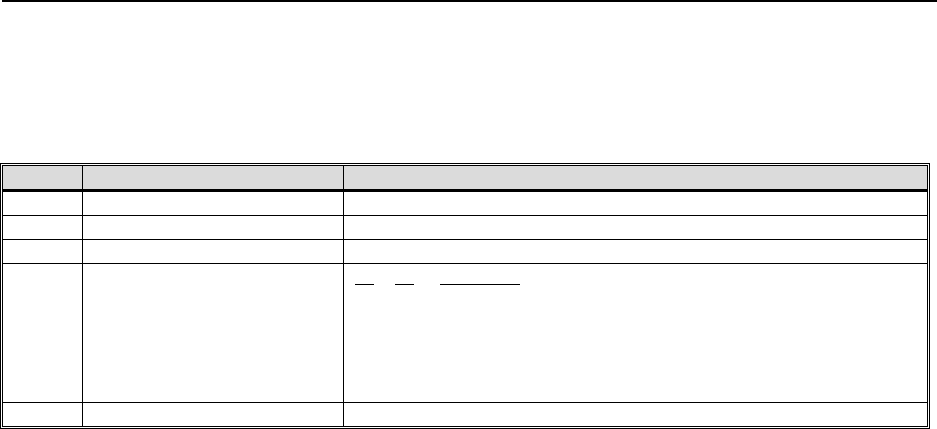
PTR for VHF-4000 and VDL-2000 Data Radios
______________________________________________________________________
______
©2000 Rockwell Collins, Inc Page 49 of 61
Appendix A Alignment Formats
The ARINC 429 Label 277 Diagnostic Request input word is defined as follows:
Bit(s) Function Contents
8-1 Label 277 (octal) 11111101 (binary)
27-9 Request Parameters Request Type specific (see below)
29-28 Sequence Number Indicates position in sequence of Request Words
31-30 Request Type 31 30 Definition
0 0 Software Version Request (Deactivated in VHF-4000)
0 1 Memory Access Request (Program, Data, or Serial
EEPROM)
1 0 Alignment Data Request
1 1 Diagnostic Data Request
32 Parity Bit Set for odd parity
The ARINC 429 Label 277 Diagnostic Request input word is used in conjunction with the ARINC 429
Label 351 Diagnostic Response output word. The Label 277 word is intended to be compatible with the
VHF-422 legacy radio’s Label 277 Bench Test Request word and will be used only on the ARINC 429
Diagnostic Data Bus.
Since read requests require up to two input Label 277 words to complete and write requests require up to
four input Label 277 words to complete, the Sequence Number field is used to specify which word in the
request is being used. For example, a Memory Access word requesting a write to Program memory
requires an input sequence of three Label 277 words. The first word has a Sequence Number of 00b and
specifies the Memory Type as “Program”, the Access Type as “Write”, and provides the required Write
Access Code (i.e., a password for enabling Memory Access writes). The second word provides the 16-bit
address within Program Space Page 1 (i.e., internal DSP RAM) of the memory location to be written and
will have a Sequence Number of 01 (binary). The third word provides the data to be written and will have
a Sequence Number of 10b. The Write Access Code in the first word of the three-word Memory Access
write request sequence is a key to prevent write access to memory by anyone but the manufacturer.
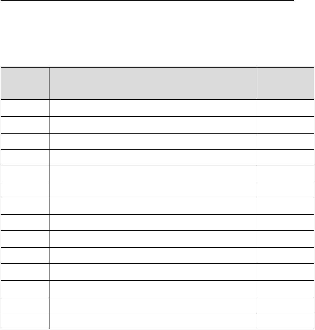
PTR for VHF-4000 and VDL-2000 Data Radios
______________________________________________________________________
______
©2000 Rockwell Collins, Inc Page 50 of 61
The number of Label 277 words required in the input sequence for each type of Label 277 diagnostic
request is defined as follows:
Request Type Operation Sequence
Length
(Label 277
Words)
00 (Software
Version) N/A N/A
01 (Memory
Access) Access Type 0 (Read), Memory Type 00 (Program Space) 2
01 (Memory
Access) Access Type 0 (Read), Memory Type 01 (Data Space) 2
01 (Memory
Access) Access Type 0 (Read), Memory Type 10 (Serial EEPROM) 2
01 (Memory
Access) Access Type 0 (Read), Memory Type 11 (Serial Number) 4
01 (Memory
Access) Access Type 1 (Write), Memory Type 00 (Program Space) 3
01 (Memory
Access) Access Type 1 (Write), Memory Type 01 (Data Space) 3
01 (Memory
Access) Access Type 1 (Write), Memory Type 10 (Serial EEPROM) 3
01 (Memory
Access) Access Type 1 (Write), Memory Type 11 (Serial Number
Locations) 4
10 (Alignment
Data) Alignment Operation Codes 0, 2, 3, & 5-A 1
10 (Alignment
Data) Alignment Operation Codes 1, 4, B, & C 2
11 (Diagnostic
Data) Diagnostic Data Operation Codes 00h-0Bh, 11h, 15h-18h, & 20h-
26h 1
11 (Diagnostic
Data) Diagnostic Data Operation Codes 27h, 28h, & 2Ah-3Ch 2
11 (Diagnostic
Data) All Other Diagnostic Data Operation Codes N/A
Every Label 277 input word will be answered with a Label 351 output word that contains a Response Type
that corresponds to the input Label 277 word’s Request Type and a Sequence Number that reflects the input
Label 277 word’s Sequence Number.
The form of the Request Parameters field for each Request Type supported via the ARINC 429 Diagnostic
Request input word is defined in the following table. In the Alignment Data requests, bits 24-27 of word
00 in the sequence are always used, regardless of the operation being requested. A write request via a
Label 277 input sequence (including Memory Access write requests, Alignment Data write requests, and
Diagnostic Data write requests) will have no effect if the VHF-4000 unit is not in Alignment Mode. Bit 27
of the Label 351 word(s) output in response to input Label 277 Alignment Data requests indicates whether

PTR for VHF-4000 and VDL-2000 Data Radios
______________________________________________________________________
______
©2000 Rockwell Collins, Inc Page 51 of 61
or not the unit is currently in Alignment Mode. Writes to sectored FLASH memory via Label 277 Memory
Access requests are not allowed. Limited access to sectored FLASH memory is available through the
Alignment Data requests. Diagnostic reads are enabled at all times.
Request
Type
(Bits 31-30)
Sequen
ce
Numbe
r
(Bits
29-28)
Request
Parameters
(Bits 27-9)
Contents
00
SW Version 00 27-9 Unused
01
Memory
Access
00 24-9
25
27-26
If bit 25 = 0 (Read) and bits 27-26 = Memory Type 00 (Program Space):
Bits 15-9 : Program Space Page for Program Space Read Accesses (bit 9 is LSB)
Bits 24-16 : Unused
If bit 25 = 0 (Read) and bits 27-26 = Memory Types 01 (Data Space) or 10 (Serial EEPROM)
or
11 (Serial Number Locations):
Bits 24-9 : Unused
If bit 25 = 1 (Write) and bits 27-26 = Memory Types 00 (Program Space) or 01 (Data Space)
or 10
(Serial EEPROM):
Bits 16-9 : Unused (All Program Space Write Accesses Go to Page 1, DSP Internal
RAM)
Bits 24-17 : Write Access Code
If bit 25 = 1 (Write) and bits 27-26 = Memory Type 11 (Serial Number Locations):
Bits 16-9 : Input LRU Serial Number 1st Alphanumeric Character (bit 9 is LSB)
Bits 24-17 : Write Access Code
Otherwise : Unused
Access Type:
0 = Read
1 = Write
Memory Type :
00 = Program Space
01 = Data Space
10 = Serial EEPROM
11 = Serial Number Locations (within LRU Configuration Data Block)
01
Memory
Access
01 24-9
27-25
For Program Space, Data Space, or Serial EEPROM Read or Write Requests:
Target Address (bit 9 is LSB)
For Serial Number Locations Write Requests:
Input LRU Serial Number 3rd & 2nd Alphanumeric Characters (bit 9 is 2nd character
LSB)
For Serial Number Locations Read Requests:
Unused
Unused
01
Memory
Access
10 24-9
27-25
For Program Space, Data Space, or Serial EEPROM Write Requests:
Value to Write to Target Address (bit 9 is LSB)
For Serial Number Locations Read Requests:
Unused
For Serial Number Locations Write Requests:
Input LRU Serial Number 5th & 4th Alphanumeric Characters (bit 9 is 4th character
LSB)
For All Other Memory Access Requests (Program/Data Space and Serial EEPROM Reads):
This word is not provided.
Unused
01
Memory
Access
11 24-9 For Serial Number Locations Read Requests:
Unused
For Serial Number Locations Write Requests:
Input LRU Serial Number 7th & 6th Alphanumeric Characters (bit 9 is 6th character
LSB)
For All Other Memory Access Requests (Program/Data Space & Serial EEPROM

PTR for VHF-4000 and VDL-2000 Data Radios
______________________________________________________________________
______
©2000 Rockwell Collins, Inc Page 52 of 61
Request
Type
(Bits 31-30)
Sequen
ce
Numbe
r
(Bits
29-28)
Request
Parameters
(Bits 27-9)
Contents
27-25 Reads/Writes):
This word is not provided.
Unused
10
Alignment
Data
00 16-9
20-17
22-21
23
24
25
26
27
If bits 20-17 = 1, 2, 3, 4 or 5 hex:
Alignment Parameter Code (see table of Alignment Parameter Codes below)
If bits 20-17 = B or C:
1st (i.e., most significant) digit of desired Installed Service Bulletin (ISO 5 character)
Otherwise:
Unused
Requested Alignment Operation Code:
0 hex : Mode Change (see Bits 24, 25, 26 and 27)
1 hex : Accept Value as Alignment Working Value
2 hex : Store Alignment Working Value in FLASH
3 hex : Read Alignment Working Value
4 hex : Store TFM Value for Given Temperature Zone in FLASH
5 hex : Read FLASH TFM for Given Temperature Zone
6 hex : Start Duty Cycle Pulse
7 hex : Stop Duty Cycle Pulse
8 hex : Start Single Side Band
9 hex : Stop Single Side Band
A hex : Clear All Archived Fault Records
B hex : Add Installed Service Bulletin
C hex : Remove Installed Service Bulletin
D hex : Spare (Unused)
E hex : Spare (Unused)
F hex : Spare (Unused)
If bits 20-17 = 4 or 5 hex:
Temperature Zone for TFM matrix FLASH storage
Otherwise:
Unused
Unused
Inhibit Tx Timer : 0 = Enable Tx Timeout Timer, 1 = Inhibit Tx Timeout Timer
Inhibit Tx Key : 0 = Enable Transmission on PA, 1 = Inhibit Transmission on PA
Inhibit Transmit Mode : 0 = Enable Transmit Mode, 1 = Inhibit Transmit Mode
Alignment Mode Select : 0 = Normal Operation, 1 = Alignment Request
10
Alignment
Data
01 24-9
27-25
If previous Label 277 word was an Alignment Data Request with a Sequence Number of 00
and a
Requested Alignment Operation Code (bits 20-17) of 1 hex or 4 hex:
Value to use as “Alignment Working Value” or as “TFM for Temp Zone” (bit 9 is LSB)
If previous Label 277 word was an Alignment Data Request with a Sequence Number of 00
and a
Requested Alignment Operation Code (bits 20-17) of B hex or C hex:
2nd (least significant) digit of desired Installed Service Bulletin (ISO 5 char in bits 16-9,
zeros in bits 24-17)
Otherwise : This word is not provided.
Unused
11
Diagnostic
Data
00 14-9
22-15
27-23
Unused
Diagnostic Data Operation Code (see the table of Diagnostic Data Operation Codes below)
Unused
11
Diagnostic
Data
01 24-9
25
27-26
For Diagnostic Data Operation Codes 27h, 28h, & 2Ah - 3Ch : Data to Write (bit 9 is LSB)
For All Other Diagnostic Data Operation Codes : This word is not provided.
Unused
Sync Count (2 LSBs of input word sync count for multiword read operations, starting w/ 00)

PTR for VHF-4000 and VDL-2000 Data Radios
______________________________________________________________________
______
©2000 Rockwell Collins, Inc Page 53 of 61
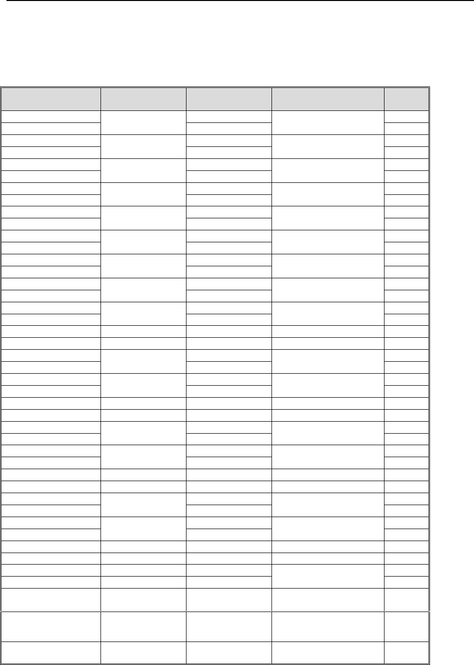
PTR for VHF-4000 and VDL-2000 Data Radios
______________________________________________________________________
______
©2000 Rockwell Collins, Inc Page 54 of 61
Appendix B Rear Connector Pins by Function
VHF-4000
Pin Name Signal/Variable
Name Variable
Setting/Contents Signal Type Pin
Number
429_CMU_HS_In_A_A 1
429_CMU_HS_In_A_B
CMU_IN_A Differential HS ARINC 429
input 2
429_Input_Port_A_A 3
429_Input_Port_A_B
TUNE_IN_A Differential HS/LS ARINC
429 input 4
429_LS_Out_1_A 5
429_LS_Out_1_B
429_LS_OUT_1 Differential LS ARINC 429
output 6
429_CMU_HS_In_B_A 7
429_CMU_HS_In_B_B
CMU_IN_B Differential HS ARINC 429
input 8
429_MAint_In_A 9
429_MAint_In_B
MAINT_IN Differential HS ARINC 429
input 10
429_LS_Out_2_A 11
429_LS_Out_2_B
429_LS_OUT_2 Differential LS ARINC 429
output 12
429_MAint_HS_Out_A 13
429_MAint_HS_Out_B
MAINT_OUT Differential HS ARINC 429
output 14
429_Input_Port_C_A 15
429_Input_Port_C_B
TUNE_IN_C Differential HS/LS ARINC
429 input 16
429_HS_Out_1_A 17
429_HS_Out_1_B
429_HS_OUT_1 Differential HS ARINC 429
output 18
RX_Audio_Out RX_AUDIO Analog output (100 mW) 19
Sidetone_Audio_Out SIDETONE_AUDIO Analog output (100 mW) 20
429_Input_Port_B_A 21
429_Input_Port_B_B
TUNE_IN_B Differential HS/LS ARINC
429 input 22
429_HS_Out_2_A 23
429_HS_Out_2_B
429_HS_OUT_2 Differential HS ARINC 429
output 24
Combined_Audio_Out COMBINED_AUDIO Analog output (100 mW) 25
Audio_Out_Return Analog output (100 mW) 26
429_Spare_In_A 27
429_Spare_In_B
Differential ARINC 429 input
28
429_Spare_Out_A 29
429_Spare_Out_B
Differential ARINC 429
output 30
Spare_Discrete_In Discrete input 31
Audio_Out_Return Analog output (100 mW) 32
CSDB_Data_In_A 33
CSDB_Data_In_B
CSDB_IN Differential CSDB input
34
CSDB_Data_Out_A 35
CSDB_Data_Out_B
CSDB_OUT Differential CSDB output
36
Selcal_Audio_Gnd Return 37
Selcal_Audio_Out SELCAL_AUDIO Analog output (0.5 V) 38
GPS_Sync_In_Lo_Sel 39
GPS_Sync_In_Hi_Sel
Differential Digital (TBD)
input 40
PTT_Sel PTT_DISC Gnd = Keyed
Open = Not Keyed
Discrete input 41
Simulcomm_Cntl_1_Sel SIMULCOM_1 See Error!
Reference source
not found.
Discrete input 42
RIU_Installed_Sel RIU_INSTALLED Gnd = RIU Installed
Open = RIU Not
Discrete input 43
PTR for VHF-4000 and VDL-2000 Data Radios
______________________________________________________________________
______
©2000 Rockwell Collins, Inc Page 55 of 61
Installed
All_Call_Disbl_Sel ALL_CALL See Error!
Reference source
not found.
Discrete input 44
Voice/Data_Sel V/D_DISC Gnd = Data
Open = Voice
Discrete input 45
Simulcomm_Cntl_2_Sel SIMULCOM_2 See Error!
Reference source
not found.
Discrete input 46
TX_Mode_Indicator TX_MODE Gnd = Transmit
Open = Receive
Discrete output 47
NC 48
Burst_Tune_Sel CONT/BURST Gnd = Burst
Open = Continuous
Discrete input 49
ARINC/CSDB_Sel A429/CSDB Gnd = A429
Open = CSDB
Discrete input 50
Port_C_Sel PORT_C Gnd = Selected
Open = Not selected
Discrete input 51
RX_Comp_Disbl_Sel RX_COMP Gnd = Disabled
Open = Enabled
Discrete input 52
NC 53
Mic_Audio_In MIC_AUDIO Analog input 54
Port_A/B_Sel PORT_A/B Gnd = B
Open = A
Discrete input 55
Unit_ID_A_Sel UID_A See Error!
Reference source
not found.
Strap input 56
WOW_Sel WOW Gnd = Ground
Open = Air
Discrete input 57
(+27.5 Vdc) Power 58
Power_Ground Power 59
Chassis_Ground Power 60
Data_Load_Enbl_Sel DATALOAD Gnd = Enabled
Open = Disabled
Discrete input 61
Unit_ID_B_Sel UID_B See Error!
Reference source
not found.
Strap input 62
Strap_Ground Strap input 63
(+27.5 Vdc) Power 64
Power_Ground Power 65
Mic_Audio_Gnd Return 66
VDL-2000
Pin Name Signal/Variable
Name Variable
Setting/Contents Signal Type Pin
Number
429CMU_HS_IN_A_A 36
429CMU_HS_IN_A_B
CMU_IN_A Differential HS ARINC 429
input 37
429MAINT_IN_A 1
429MAINT_IN_B
MAINT_IN Differential HS ARINC 429
input 32
429_MAINT_HSOUT_A 6
429_MAINT_HSOUT_B
MAINT_OUT Differential HS ARINC 429
output 7
429CMU_HS_OUT_A 5
429CMU_HS_OUT_B
CMU_OUT Differential HS ARINC 429
output 22
429CMU_HS_IN_B_A CMU_IN_B Differential HS ARINC 429
input 28
PTR for VHF-4000 and VDL-2000 Data Radios
______________________________________________________________________
______
©2000 Rockwell Collins, Inc Page 56 of 61
429CMU_HS_IN_B_B 2
422_DATA_IN_A 20
422_DATA_IN_B
422_DATA_IN Differential RS422 Input
21
422_DATA_OUT_A 24
422_DATA_OUT_B
422_DATA_OUT Differential RS422 Output
23
RX_AUDIO_OUT RX_AUDIO Analog output (100 mW) 33
SIDETONE_AUDIO_OUT SIDETONE_AUDIO Analog output (100 mW) 31
AUDIO_OUT_RETURN Return 19
SPARE_DISCRETE_IN Discrete input 13
PTT_SEL PTT_DISC Gnd = Keyed
Open = Not Keyed
Discrete input 35
SCOM_CNTL_1_SEL SIMULCOM_1 See Simulcomm
Strapping Discrete input 16
SCOM_CNTL_2_SEL SIMULCOM_2 See Simulcomm
Strapping Discrete input 34
VOICE_DATA_SEL V/D_DISC Gnd = Data
Open = Voice
Discrete input 17
TX_MODE_IND TX_MODE Gnd = Transmit
Open = Receive
Discrete input 3
MIC_AUDIO_IN MIC_AUDIO Analog input 4
WOW_SEL WOW Gnd = Ground
Open = Air
Discrete input 14
UNIT_SDI_A_SEL UID_A See Unit ID setting Strap input 15
UNIT_SDI_B_SEL UID_B See Unit ID setting Strap input 18
SYSTEM_ON_F SYSTEM_ON_F OPEN=OFF
0-7 VDC ON
Discrete input 27
DATALOAD_ENB_SEL DATALOAD Gnd = Enabled
Open = Disabled
Discrete input 29
(+28VDC_PRI_PWR_H_1) 28VDC Power 10
(+28VDC_PRI_PWR_H_2) 28VDC Power 11
(+28VDC_PRI_PWR_L_1) 28VDC Power Return 8
(+28VDC_PRI_PWR_L_2) 28VDC Power Return 9
CHASSIS_GROUND Chassis Ground 12
MIC_AUDIO_GND Return 30
NC_1 No Connect 26
NC_2 No Connect 25
Unit Simulcomm Strapping
Simulcom_Cntl_1_Sel Simulcom_Cntl_2_Sel Threshold Level (dBm)
0 (ground) 0 (ground) Attenuator Disabled (> 0 dBm)
0 (ground) 1 (open) Programmable Value 1 (-10 dBm)
1 (open) 0 (ground) Programmable Value 2 (-30 dBm)
1 (open) 1 (open) Programmable Value 3 (-20 dBm)
(preferred condition)
Programmable values should be able to implement attenuation thresholds over the range of 0 - -30 dBm.
SDI setting is defined as follows:
PTR for VHF-4000 and VDL-2000 Data Radios
______________________________________________________________________
______
©2000 Rockwell Collins, Inc Page 57 of 61
UID B Discrete UID A Discrete Unit’s SDI Setting
0 0 11 (VHF 3)
0 1 10 (VHF 2)
1 0 01 (VHF 1)
1 1 00 (VHF 4, if All Calls
disabled)
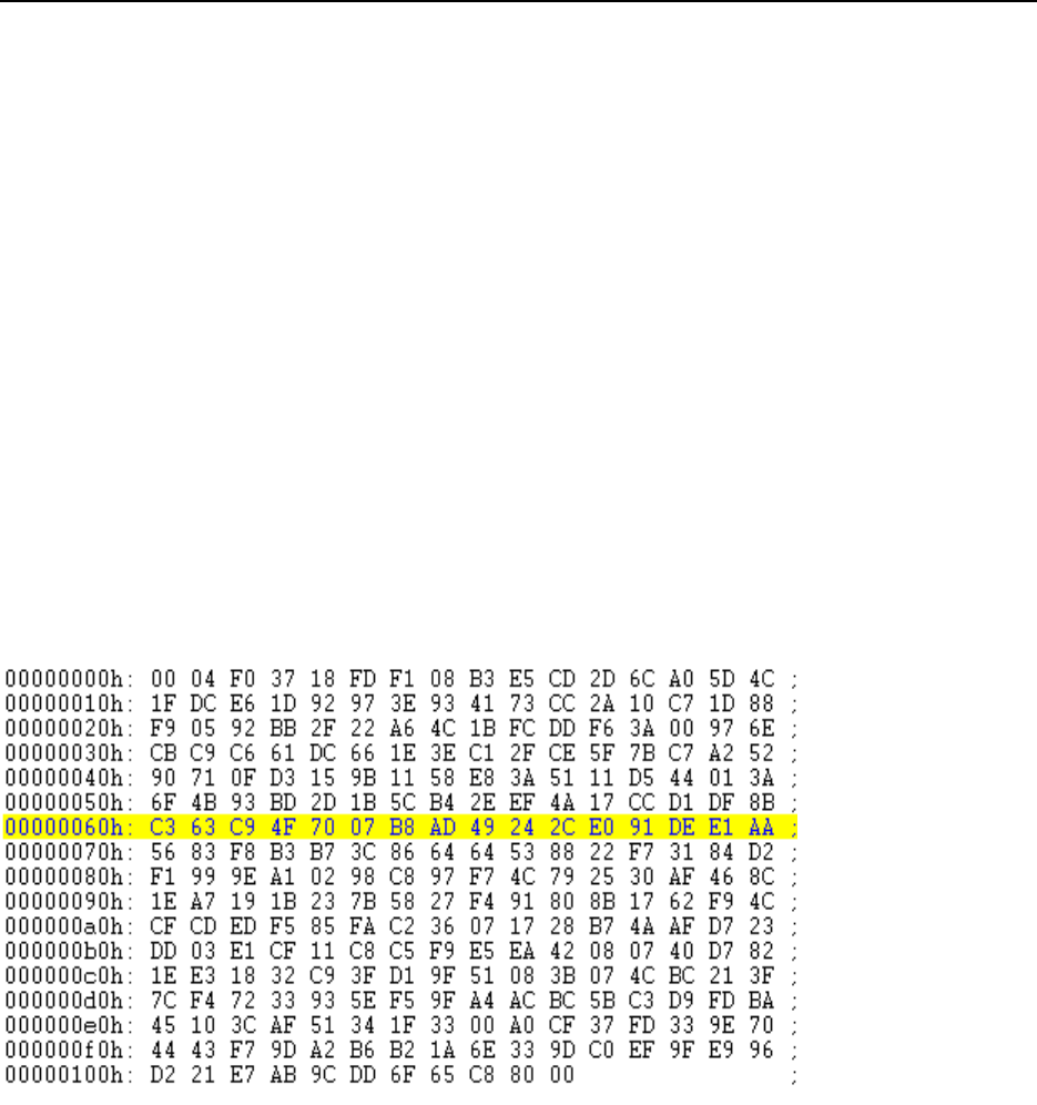
PTR for VHF-4000 and VDL-2000 Data Radios
______________________________________________________________________
______
©2000 Rockwell Collins, Inc Page 58 of 61
Appendix C - VDL Mode 2 Operation
The BFR test message is a VDL Mode 2 message containing 249 application bytes. The message will also
contain 6 Reed Solomon check bytes for a total of 255 bytes. The normal VDL preamble containing the
following segments must also be contained in the message:
a) 12 bits (4 symbols) for transmitter power ramp up;
b) 48 bits (16 symbols) for synchronization
c) 3 bits as the reserved symbol
d) 17 bits transmission length
e) 5 bits header FEC.
Refer to DO-224A, “Signal-in-Space Minimum Aviation System Performance Standards
(MASPS) for Advanced VHF Digital Data Communications Including Compatibility with
Digital Voice Techniques”, September 13, 2000, for specific details on the composition of
VDL Mode 2 message and waveform.
A suitable test message is shown in hex format as follows :
The message starts with 000 hex which is 12 bits (4 symbols) of constant signal which is
the ramp up for VDL Mode 2.

PTR for VHF-4000 and VDL-2000 Data Radios
______________________________________________________________________
______
©2000 Rockwell Collins, Inc Page 59 of 61
For any transmit or receive tests in VDL Mode 2, the unit must first be placed in VDL
Mode 2:
1) Ground the Voice/Data Discrete
2) Transmit 0008001D#, 8000235E# on CMU Port A input. This message must be sent at a
rate of at least once a second to maintain VDL Mode 2 operation.
3) Monitor CMU output bus for a label 270 message. Bits 20 – 24 show the mode status of the
radio, the status should be 0010.
4) Transmit 47000315# (ALO) on CMU Port A input.
5) Monitor CMU output bus for a label 270 message. Bits 20 – 24 show the mode status of the
radio, the status should be 0110.
6) Transmit D2050015# (Mode_Set.request) on CMU Port A input.
7) Monitor CMU output bus for a label 270 message. Bits 20 – 24 show the mode status of the
radio, the status should be 0111.
8) Transmit D201F115# (Pr_Set.request) on CMU Port A input.
9) Monitor CMU output bus for a label 270 message. Bit 11 should be set to 1 and Bit 14 11
should be set to 1 (Protocol Reset State).
10) Transmit one of the operating frequencies below on CMU Port A input.
11) Monitor CMU output bus for a label 270 message. Bit 11 should be set to 0 and Bit 14 11
should be set to 1 (Protocol Set State).
To set desired operating frequency in transmit and receive send the following
message on the CMU Port A input for the desired frequency:
a) 118.000 MHz command words:
AF040715# 020F115# 1207015# 84000015# 00100115# 99000015# B18CC815#
b) 118.425 MHz command words:
AF040715# 0020F115# 81207015# 04002A15# 00100115# 99000015# 3120A615#
c) 119.425 MHz command words:
AF040715# 0020F115# 01307015# 04002A15# 00100115# 99000015# B1BF7315#
d) 120.425 MHz command words:
AF040715# 0020F115# 81407015# 04002A15# 00100115# 99000015# 31786B15#
e) 121.425 MHz command words:
AF040715# 0020F115# 01507015# 04002A15# 00100115# 99000015# B1E7BE15#
f) 122.425 MHz command words:
AF040715# 0020F115# 01607015# 04002A15# 00100115# 99000015# B14FD015#

PTR for VHF-4000 and VDL-2000 Data Radios
______________________________________________________________________
______
©2000 Rockwell Collins, Inc Page 60 of 61
g) 123.425 MHz command words:
AF040715# 0020F115# 81707015# 04002A15# 00100115# 99000015# 31D00515#
h) 124.425 MHz command words:
AF040715# 0020F115# 81807015# 04002A15# 00100115# 99000015# 31C9F115#
i) 125.425 MHz command words:
AF040715# 0020F115# 01907015# 04002A15# 00100115# 99000015# B1562415#
j) 126.000 MHz command words:
AF040715# 0020F115# 01A07015# 84002A15# 00100115# 99000015# 31522415#
k) 126.425 MHz command words:
AF040715# 0020F115# 01A07015# 04002A15# 00100115# 99000015# B1FE4A15#
l) 127.425 MHz command words:
AF040715# 0020F115# 81B07015# 04002A15# 00100115# 99000015# 31619F15#
m) 128.425 MHz command words:
AF040715# 0020F115# 01C07015# 04002A15# 00100115# 99000015# B1A68715#
n) 129.425 MHz command words:
AF040715# 0020F115# 81D07015# 04002A15# 00100115# 99000015# 31395215#
o) 130.425 MHz command words:
AF040715# 0020F115# 81E07015# 04002A15# 00100115# 99000015# 31913C15#
p) 131.425 MHz command words:
AF040715# 0020F115# 01F07015# 04002A15# 00100115# 99000015# B10EE915#
q) 132.425 MHz command words:
AF040715# 0020F115# 02007015# 04002A15# 00100115# 99000015# B1C15715#
r) 133.425 MHz command words:
AF040715# 0020F115# 82107015# 04002A15# 00100115# 99000015# 315E8215#
s) 134.425 MHz command words:
AF040715# 0020F115# 82207015# 04002A15# 00100115# 99000015# 31F6EC15#
t) 135.425 MHz command words:
AF040715# 0020F115# 02307015# 04002A15# 00100115# 99000015# B1693615#
u) 136.425 MHz command words:
AF040715# 0020F115# 82407015# 04002A15# 00100115# 99000015# 31AE2115#
v) 136.975 MHz command words:
AF040715# 0020F115# 82407015# 04002A15# 00100115# 99000015# 3181D515#
To verify receipt of a message transmited to UUT by a VDL Mode 2 signal generator:
1) Send address request message after sending the frequency request :

PTR for VHF-4000 and VDL-2000 Data Radios
______________________________________________________________________
______
©2000 Rockwell Collins, Inc Page 61 of 61
2F 04 09 15# 80 22 F1 15# 00 10 D0 15# 05 55 55 15# 8F E5 55 15# 8E FE FE 15# 0F EF
2F 15#
1B FE FE 15# 31 D3 11 15#
2) Transmit VDL Mode 2 test message and monitor CMU output port for Label 304. Bytes 5 & 6
should have data 51# & F1# respectively to indicate a message was just received by UUT.
To Transmit the VDL Mode 2 test message from the UUT send the following
message on the CMU Port A input to transmit a single message:
AF446615# 8021F115# 000F5015# 05555515# 05555515# 05555515# 03055515#
01303115# 83332315# 86353415# 03837315# 82413915# 04443415# 8D464515
#
0300A015# 01303115# 83332315# 86353415# 03837315# 82413915# 04443415#
8D464515# 0300A015# 01303115# 83332315# 86353415# 03837315# 82413915#
04443415# 8D464515# 0300A015# 01303115# 83332315# 86353415# 03837315#
82413915# 04443415# 8D464515# 0300A015# 01303115# 83332315# 86353415#
03837315# 82413915# 04443415# 8D464515# 0300A015# 01303215# 83332315#
86353415# 03837315# 82413915# 04443415# 8D464515# 0300A015# 01303215#
83332315# 86353415# 03837315# 82413915# 04443415# 8D464515# 0300A015#
01303215# 83332315# 86353415# 03837315# 82413915# 04443415# 8D464515
#
0300A015# 01303215# 83332315# 86353415# 03837315# 82413915# 04443415#
8D464515# 0300A015# 01303215# 83332315# 86353415# 03837315# 82413915#
04443415# 8D464515# 0300A015# 81303315# 83332315# 86353415# 03837315#
82413915# 04443415# 8D464515# 0300A015# 81303315# 03E32315# 8E3E3E15
#
03E3E315# 8D3E3E15# 9A00A015# 3138B415#