Rockwell Collins 8222532 LANDING UNIT RECEIVER User Manual
Rockwell Collins Inc LANDING UNIT RECEIVER
User Manual
Rockwell Collins, Inc.
GLU-2100
User’s Manual
This manual is provided for FCC test guidance, it shall not be used for any other reason but this.

1.1 Scope
This document will detail information required to install and use the GLU-2100 unit.
1.1 Overview
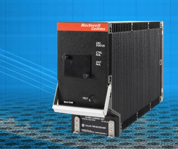
The GLU-2100 is packaged in an ARINC 600 size 3 MCU case to receive and process ILS,
GLS, VOR, MB, and GNSS signals.
The GLU-2100 is a navigation sensor with internal receivers used for enroute, terminal, and
instrument approach and landing operation.
A NAV CCA provides ILS flight path deviation guidance for precision approach and landing as
well as VOR/Marker Beacon functions. The VOR function receives, decodes, and processes
bearing information from the transmitted VOR signal, while the Marker Beacon function provides
visual and aural identification when the aircraft is over a marker beacon transmitter by
illuminating one of three indicator lamps and outputting one of three audible tones (400, 1300,
or 3000 Hz). A Global Navigation Satellite System (GNSS) CCA provides navigation data for
other aircraft systems to support enroute, terminal, precision, and non-precision approach
operations.
The NAV CCA section receives very high frequency (VHF) localizer signals in the frequency
range of 108.00 to 111.95 MHz, and ultra-high frequency (UHF) glideslope signals in the
frequency range of 328.6 to 335.4 MHz. The NAV CCA additionally receives very high
frequency data broadcast (VDB) signals in the frequency range of 108.00 to 117.975 MHz in
GLS mode. The GNSS CCA section receives signals from the Global Positioning System (GPS)
nominal carrier frequency of 1575.42 MHz.
1.2 Input/Output Data Buses
The following Input and Output Data Buses are available on the GLU-2100:
1.2.1 Input: Air Data / FMS Bus (2 Buses)
Automatic Test Equipment Bus
Data Loader Bus
Inertial Reference System / ADIRU Bus (3 Buses)
OMS/ CFDS Bus
Tune/ Function Select Data Bus (2 Buses)
1.2.2 Output: Automatic Test Equipment
Data Loader
GNSS (3 Buses)
ILS Look Alike (2 Buses)
MMR Data Broadcast
OMS/ CFDS
1.3 Mechanical Description
The GLU-2100 is packaged in an ARINC 600 size 3 MCU case. A low insertion force
size 2 connector on the rear of the unit interfaces with the aircraft wiring. The connector
also holds the rear of the unit to the equipment rack. The GLU-2100 is cooled with
forced-air supplied to inlet holes on the bottom of the unit and exhausted through outlet
holes on the top of the unit.
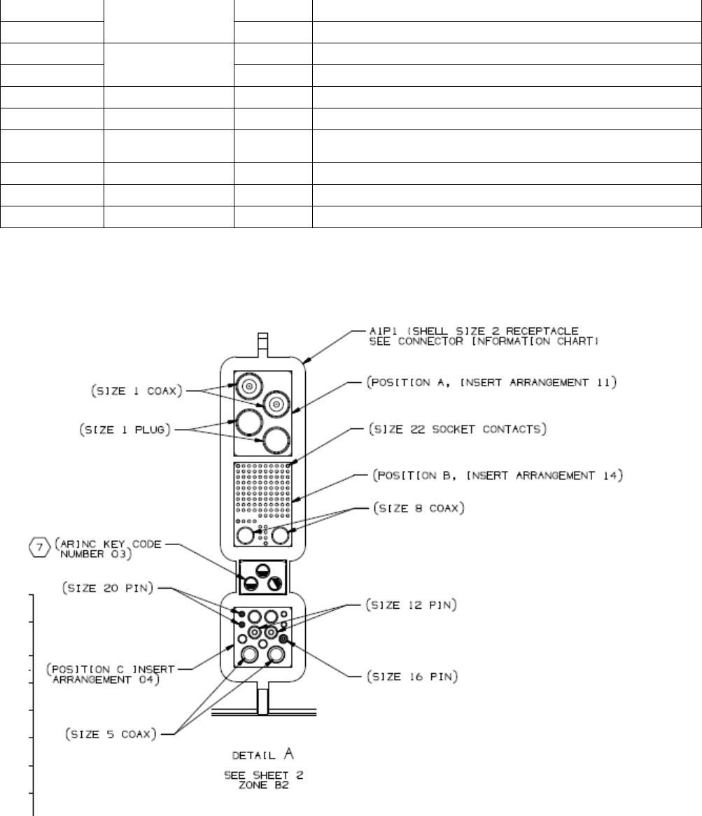
The GLU-2100 chassis consists of top and bottom plates, front panel, left and right
hinged swingout side covers, and a rear connector mounted in an assembly that protects
against high intensity radiated fields (HIRF). The top insert of the rear connector is for
the GNSS antenna connection, the middle insert is for service connections and VOR/MB
antenna connections, and the bottom insert is for power and LOC/GS antenna
connections.
Access to the interior of the GLU-2100 is gained by removing the left or right side
covers. The side covers are mounted on hinges and held to the chassis with captive
screws. When the captive screws are released, the covers can be swung open.
1.4 Power Supply
The GLU-2100 operates on 115 V ac, 400 Hz single phase power supplied by the
aircraft. The input power is routed from the rear interconnect to the forward power
supply.

2 DESIGN
2.1 GLU-2100 Design Characteristics
This section provides lists of weights, dimensions, and power usage, and applicable
drawings and documents for the GLU-2100. This information is presented in Table 1.
Table 1 – GLU-2100 Design Characteristics
CHARACTERISTIC
SPECIFICATION
Connector
Rear connector
Rear connector RCPN 859-2777-630
ARINC 600 size 2 shell with three inserts and an
index pin code of 03
Top plug insert arrangement 11
Middle plug insert arrangement 14
Bottom plug insert arrangement 04
Localizer receiver
characteristics
Frequency range
108.00 - 111.95 MHz
Channel spacing
50 kHz (40 channels), 108.10 MHz to 111.95 MHz
Antennas
50 Ohms Nominal
Receiver sensitivity
Aural sensitivity 6 dB (S+N)/N minimum, over the range –99
to –33 dBm
Valid data threshold −110 dBm minimum (+/- 2.0 dBm)
Identification tone threshold −93 dBm at percent
modulation, 1020 Hz
Glideslope receiver
characteristics
Frequency range
328.6 to 335.4 MHz
Channel spacing
150 kHz (40 channels), from 329.15 to 335.0 MHz
Antenna input
50 Ohms (nominal)
Receiver sensitivity
Valid data threshold −87 dBm minimum
Instrumentation
Localizer deviation accuracy
Centering
± 0.004 DDM, 95% probability
± 0.004 DDM, bench
Glideslope deviation accuracy
Centering
± 0.0093 DDM, 95% probability
± 0.0093 DDM, bench

Localizer audio output level
Adjustable 5 to 40 mW, -87 dBm to -33 dBm, for standard
localizer signal, modulated 30 percent at 1000 Hz into 600-
ohm load
CHARACTERISTIC
SPECIFICATION
VDB receiver characteristics
Frequency range
108.000 - 117.975 MHz
Channel spacing
25 KHz
Receiver sensitivity
Message failure rate ≤ 0.15%, with an input power
level of −87 dBm
VOR receiver characteristics
Frequency range
108.00 - 117.95 MHz
Channel spacing
50 kHz
Antenna input
50 Ohms (nominal)
Receiver sensitivity
Aural sensitivity 6 dB (S+N)/N minimum, over the
range –109.5 to –27 dBm
Valid data threshold −110 dBm minimum (+0.5 / -2.0
dBm)
Identification tone threshold −109.5 dBm at percent
modulation, 1020 Hz
VOR audio output level
Adjustable 5 to 40 mW, -98 dBm to -33 dBm, for
standard VOR signal, modulated 30 percent at 1000
Hz into 600-ohm load
MB receiver characteristics
Frequency range
75 MHz
Antenna input
50 Ohms (nominal)
Receiver sensitivity
Aural sensitivity 6 dB (S+N)/N minimum, 15 dBm
range of threshold (-67 dBm for high, -53 dBm for low)
to -13 dBm
Valid data threshold –67 dBm (High), –53 dBm (Low)
GNSS receiver characteristics
Frequency
1575.42 MHz
Channels
14 GPS channels, 4 SBAS channels
(Primary/Monitor)
Time to first fix
Worst Case 300 seconds (5 minutes) with or without
initialization (95%)
Accuracy (Non SBAS/GBAS)
Horizontal 15 meters 95% (HDOP 1.5) SA OFF
Vertical 21 meters 95% (VDOP 3) SA OFF

CHARACTERISTIC
SPECIFICATION
Receiver sensitivity
GPS MOPS Testing performed to a signal level of -
120.5 dBm at the input to the receiver
3 Installation
The picture below details the GLU-2100 unit mounted in the ARINC 600 3MCU mount. These
type mounts have mechanical mechanisms to allow capture and restraint of the front feet of the
unit. This restraint ensures the unit will not come loose from the mount and also that the ARINC
defined connector does remains in contact with the rear pins.
The harness that connects the RMP to the GLU-2100 is defined by the aircraft manufacturer.
The pinout can be found below.
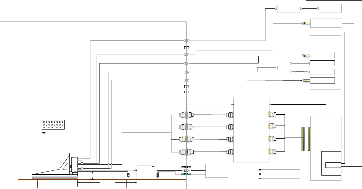
The equipment setup comes with a complete setup station and wiring going to a standard EMI
bulkhead and from the EMI Bulkhead to the test equipment as shown in the pictures below.
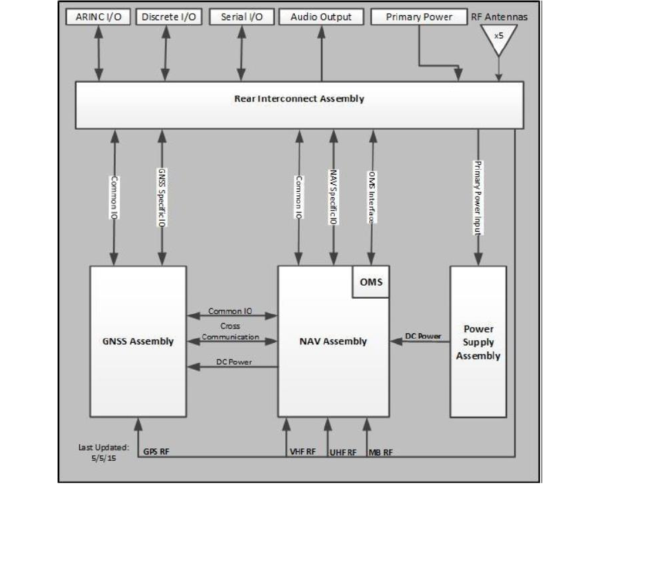
Figure 1 -GLU-2100 Module Interfaces
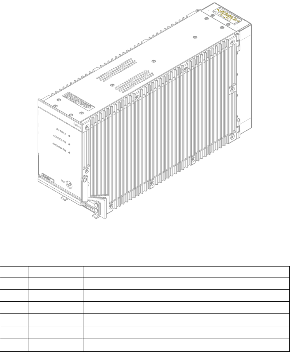
Figure 2 - GLU-2100 Unit overview
Table 2 - Critical Frequency List
#
Frequency (MHz)
Description
1.
178.752
NAV Serial ADC Output
2.
240
GNSS ADC Data Clock
3.
375
NAV Processor Internal Clock
4.
1101
GNSS L5 LO
5.
1500
GNSS L1 LO
6.
1602
GNSS Glonass LO
1 2 3 4 5 6 7 8 9 10 11 12 13 14 15 16 17 18
Blank Panel
Blank Panel
NI PXIe-1085
MXI Express Cable (PN: 782317-03)
Blank Panel
Blank Panel
Blank Panel
Blank Panel
TO PXI Chassis 1 PXIe-8434
PXIe-8381
NI PXIe-5644R
RF Out 0
RF IN 0
NI PXIe-5644R
RF Out 0
RF IN 0
NI PXIe-5644R
RF Out 0
RF IN 0
NI PXIe-5644R
RF Out 0
RF IN 0
LOC
GS
VOR
VDB
RG316 (SMA to SMA)
To Qual Cable LOC RF input
RG316 (SMA to SMA)
Ground Strap
Connected to chassis frame
S
1
2
Combiner
Amphenol PN:
135101-01-24.00
Mini Circuits PN
ZAPD-2-252-S+
Amphenol PN:
135101-01-24.00
To Qual Cable VOR RF input
To Qual Cable GS RF input
6 dB Attenuator
Crystek PN: CATTEN-06R0
Multi-GNSS Simulator
Spirent GSS6700
Noise Box
USB Cable 2.0 - Type A to Type B
P3
Mon
Cal
TO PXI Chassis 1 PXIe-8434
P4
Signal Generator
Rohde & Schwarz SMB 100A
To Qual Cable MB RF input
6 dB Attenuator
Crystek PN: CATTEN-06R0
6 dB Attenuator
Crystek PN: CATTEN-06R0
RG316 (SMA to SMA)
Amphenol PN:
135101-01-24.00
Figure 3 External generators for Flight Test Pallet (provided)
GNSS #1
VDB
GLU-2100
P12
P18
LISN
10uf Capacitor
Y
Ground Plane
LOC
GS
VOR
MB
GNSS #1
LOC
GS
VOR
GNSS #2
MB
SPARE 1
SPARE 2
P50
653-5879-007
653-5879-008
653-5879-009
653-5879-010
663-0055-001
653-5879-011
653-5875-004
J100
P8
P7
P5
P9
P10
J1
J2
J3
J4
Bulkhead
A
B
C
P11
P23
653-5879-025
653-5879-025
653-5879-025
653-5879-025
P1
P14
P16
P15
P17
P2
P3
P4
P28
P29
P31
P30
J28
J29
J31
J30
P24
P25
P26
P27
J24
J25
J26
J27
J101
J201
J301
J401
P101
P201
P301
P401
Program Pins
P32
PXI Express Chassis
Flight Test Pallet
Controller
VST
VST
VST
Any of iCon
Receiver #1 - #4
115 VAC COLD
CHASSIS GND
115 VAC HO T
115 VAC HO T
115 V AC, 400
Hz Power Supply
115 VAC C OLD
CHASSIS GND
EMI Tile Room
1 m (+0 / -5 cm)
V2
G1
V1
Signal Generator
Combiner
Load / Lightning
Box
Note 4
Multi-GNSS
Simulator
Noise Box
RG316
Vector Signal TXR
RG316
RG316
LOC / VDB
PXI Express
Chassis
Controller
USB Cable
MXI Express Cable
P37P36
P22
P21
P18
663-0052-001
P4 P3
To GND BLK 8 Note 9 Note 9
Note 1
Note 8
Note 5
Note 6
USB Cable
Figure 4 Test Setup with Flight Test Pallet and PXIe Rack

Table 3 EUT Monitoring Test Equipment
Description
Manufacturer
Model
Quantity
Comments
3 MCU Mounting Tray
Rockwell Collins
653-5879-030
1
LISN
FCC
FCC-LISN-5-
50-1-01-DEF-
STAN-59-41
1
EMI / EME tests
GLU-2100 Product Line EMI
Cable Assembly
Rockwell Collins
653-5875-004
1
Grounding Block
Rockwell Collins
653-5879-027
1
For program pins
Bulkhead
Rockwell Collins
653-5875-033
1
Bulkhead Exterior to Front
Panel Cable
Rockwell Collins
653-5879-025
5
Bulkhead Exterior to Load
Box Cable
Rockwell Collins
653-5879-007
1
Bulkhead Exterior to Load
Box Cable
Rockwell Collins
653-5879-008
1
Bulkhead Exterior to Load
Box Cable
Rockwell Collins
653-5879-009
1
Bulkhead Exterior to Load
Box Cable
Rockwell Collins
653-5879-010
1
Load / Lightning Box
Rockwell Collins
663-0055-002
1
Power Supply
Agilent E3630A
469-0075-009
1
8V Supply for Load /
Lightning Box
Load Box to Test Station
Front Panel Cable
Rockwell Collins
653-5879-011
1
GLU-2100 Flight Pallet
Rockwell Collins
983-8406-250
1
18-Slot 3U PXI Express
Chassis
National
Instruments
PXIe-1085
1
If using Flight Test
Pallet
PXI Express Controller
National
Instruments
PXIe-8381
1
Installed in PXIe
Chassis when using
Flight Test Pallet
6 GHz Vector Signal
Transceivers
National
Instruments
PXIe-5644R
4
Installed in PXIe
Chassis when using
Flight Test Pallet

Description
Manufacturer
Model
Quantity
Comments
MXI-Express Cable, 3m
National
Instruments
782317-03
1
To connect PXIe
controller when using
Flight Test Pallet
Signal Generator
Rohde & Schwarz
SMB 100A
1
For MB when using
Flight Test Pallet
Multi-GNSS Simulator
Spirent
GSS6700
1
For GNSS when
using Flight Test
Pallet
Noise Box
Rockwell Collins
983-8406-226
1
Use with Simulator
when using Flight
Test pallet
USB 2.0 Cable – Type A to
Type B, 6 foot
General Purpose
General
Purpose
1
To connect Simulator
to PXIe when using
Flight Test pallet
6 dB Attenuator
Crystek
CATTEN-
06R0
4
Use with VSTs and
signal generator
when set up with
Flight Test Pallet
RG-316/U SMA Cable
Assembly
Amphenol
135101-01-
24.00
3
To connect VSTs to
Combiner, and
Simulator to Noise
Box when using
Flight Test Pallet
Coax Power
Splitter/Combiner
Mini Circuits
ZAPD-2-252+
1
To couple VDB when
using Flight Test
Pallet
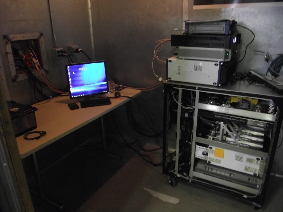
Figure 5 Flight Test Pallet (Outside EMI Chamber)
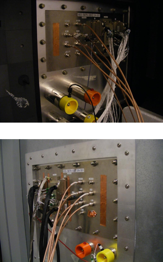
Figure 6 Bulkhead Plate – EUT Side
Figure 7 Bulkhead Plate – Test Station Side
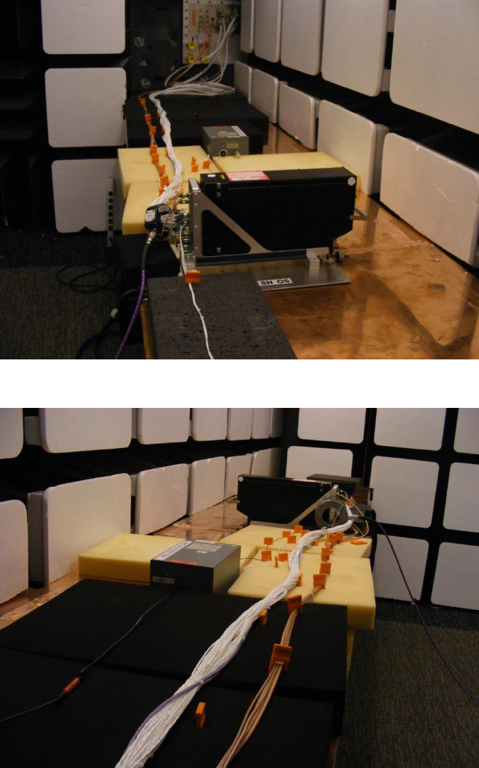
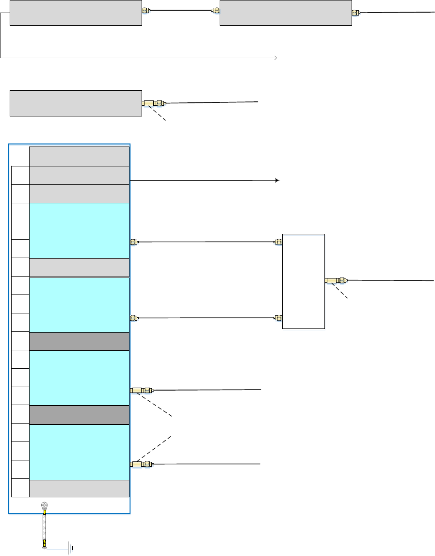
Figure 8 Cable Layout – EUT Perspective
Figure 9 Cable Layout – Bulkhead Perspective

Table 4 Pin Out List
Populated in
HW?
Signal Type
Pin Index
Pin Name / Function
Populated
ARINC 429 Output
MP-1A
ILS Look Alike (AFCS) #1 TX A
Populated
MP-1B
ILS Look Alike (AFCS) #1 TX B
Populated
ARINC 429 Input
MP-1C
Tune/Function Select Data Port AA
Populated
MP-1D
Tune/Function Select Data Port AB
Populated
ARINC 429 Input
MP-1E
OMS/CFDS RX A
Populated
MP-1F
OMS/CFDS RX B
Populated
ARINC 429 Output
MP-1G
ILS Look Alike (Inst) #2 TX A
Populated
MP-1H
ILS Look Alike (Inst) #2 TX B
Populated
ARINC 429 Input
MP-1J
Tune/Function Select Data Port BA
Populated
MP-1K
Tune/Function Select Data Port BB
Populated
Clock Output
MP-2A
GNSS Time Mark #1 Out A
Populated
Clock Output
MP-2B
GNSS Time Mark #1 Out B
Populated
ARINC 429 Output
MP-2C
GNSS Data #1 TX A
Populated
MP-2D
GNSS Data #1 TX B
Populated
ARINC 429 Output
MP-2E
OMS/CFDS TX A
Populated
MP-2F
OMS/CFDS TX B
Populated
Clock Output
MP-2G
GNSS Time Mark #2 Out A
Populated
Clock Output
MP-2H
GNSS Time Mark #2 Out B
Populated
ARINC 429 Output
MP-2J
GNSS Data #2 TX A
Populated
MP-2K
GNSS Data #2 TX B
Populated
ARINC 429 Output
MP-3A
Data Broadcast Output Data TX A
Populated
MP-3B
Data Broadcast Output Data TX B
Populated
ARINC 429 Input
MP-3C
Reserved for External Data Broadcast On-Side (#1) RX A
Populated
MP-3D
Reserved for External Data Broadcast On-Side (#1) RX B
Populated
ARINC 429 Input
MP-3E
SDME Input
Populated
MP-3F
SDME Input
Populated
ARINC 429 Output
MP-3G
SDME Output
Populated
MP-3H
SDME Output
Populated
ARINC 429 Input
MP-3J
Reserved for External Data Broadcast Cross-Side (#2) RX
A
Populated
MP-3K
Reserved for External Data Broadcast Cross-Side (#2) RX
B
Populated
Discrete Input
MP-4A
AIR/GND Discrete
Populated
Discrete Input
MP-4B
Landing Antenna Select
Populated
Discrete Input
MP-4C
Tune/Function Select Data Source A/B
Populated
Discrete Input
MP-4D
Data Loader Enable
Populated
ARINC 429 Input
MP-4E
IRS Cross-Side B (#3) RX A
Populated
MP-4F
IRS Cross-Side B (#3) RX B

Populated
Discrete Input
MP-4G
Functional Test
Populated
Discrete Input
MP-4H
SDI Input #1
Populated
Discrete Input
MP-4J
SDI Input #2
Populated
Discrete Input
MP-4K
Program Common
Populated
Discrete Input
MP-5A
VHF Antenna Select Acknowledge
Populated
Discrete Input
MP-5B
Output Data Not Interrupt
Populated
Discrete Output
MP-5C
VHF Antenna Switch Control
Populated
Discrete Input
MP-5D
Output Data Interrupt
Populated
ARINC 429 Output
MP-5E
Data Loader TX A
Populated
MP-5F
Data Loader TX B
Populated
Discrete Input
MP-5G
Airplane Program Pin #1
Populated
Discrete Input
MP-5H
Airplane Program Pin #2
Populated
Discrete Input
MP-5J
Airplane Program Pin #5
Populated
Discrete Output
MP-5K
Antenna Switch Position Acknowledge
Populated
ARINC 429 Input
MP-6A
FMS Data On-Side (#1) RX A
Populated
MP-6B
FMS Data On-Side (#1) RX B
Populated
Discrete Input
MP-6C
Discrete Input (Spare)
Populated
Discrete Input
MP-6D
Discrete Input (Spare)
Populated
ARINC 429 Input
MP-6E
Data Loader RX A
Populated
MP-6F
Data Loader RX B
Populated
ARINC 429 Input
MP-6G
FMS Data Cross-Side (#2) RX A
Populated
MP-6H
FMS Data Cross-Side (#2) RX B
Populated
Discrete Input
MP-6J
Discrete Input (Spare)
Populated
Discrete Input
MP-6K
Discrete Input (Spare)
Populated
Discrete Input
MP-7A
Marker Beacon Sensitivity Discrete Input
Populated
Discrete Input
MP-7B
Marker Beacon Inhibit Discrete Input
Populated
Discrete Input
MP-7C
Discrete Input (Spare)
Populated
Discrete Input
MP-7D
Airplane Program Pin #3
Populated
Clock Output
MP-7E
GNSS Time Mark #3 Out A
Populated
Clock Output
MP-7F
GNSS Time Mark #3 Out B
Populated
Discrete Input
MP-7G
Airplane Program Pin #4
Populated
Discrete Output
MP-7H
Outer Marker / Program State 1
Populated
Discrete Output
MP-7J
Middle Marker / Program State 2
Populated
Discrete Output
MP-7K
Inner Marker / Program State 3
Populated
ARINC 429 Input
MP-8A
IRS On-Side (#1) RX A
Populated
MP-8B
IRS On-Side (#1) RX B
Populated
ARINC 429 Input
MP-8C
DADS/FMS On-Side (#1) RX A
Populated
MP-8D
DADS/FMS On-Side (#1) RX B

Populated
ARINC 429 Input
MP-8E
LRRA RX A
Populated
MP-8F
LRRA RX B
Populated
ARINC 429 Input
MP-8G
IRS Cross-Side A (#2) RX A
Populated
MP-8H
IRS Cross-Side A (#2) RX B
Populated
ARINC 429 Input
MP-8J
DADS/FMS Cross-Side (#2) RX A
Populated
MP-8K
DADS/FMS Cross-Side (#2) RX B
Populated
Audio Output
MP-9A
VOR Audio High
Populated
MP-9B
VOR Audio Low
Populated
ARINC 429 Output
MP-9C
Future Spare (Contact)
Populated
MP-9D
Future Spare (Contact)
Populated
ARINC 429 Output
MP-9E
GNSS Data #3 TX A
Populated
MP-9F
GNSS Data #3 TX B
Populated
Audio Output
MP-9G
Marker Beacon Audio High
Populated
MP-9H
Marker Beacon Audio Low
Populated
ARINC 429 Output
MP-9J
Future Spare (Contact)
Populated
MP-9K
Future Spare (Contact)
Not
Populated
TBD Output
MP-10A
APM Power
Not
Populated
TBD Output
MP-10B
APM Clock
Not
Populated
TBD Input
MP-10C
APM Data In
Not
Populated
TBD Output
MP-10D
APM Data Out
Populated
Discrete Input
MP-10E
Feature Program #1
Populated
Discrete Input
MP-10F
Feature Program #2
Populated
Discrete Input
MP-10G
Feature Program #3
Populated
Discrete Input
MP-10H
Feature Program #4
Populated
Audio Output
MP-10J
xLS Audio Output High
Populated
MP-10K
xLS Audio Output Low
Populated
ARINC 615A
Output
MP-11A
ARINC 615A TX High
Populated
MP-11B
ARINC 615A TX Low
Populated
ARINC 615A Input
MP-11C
ARINC 615A RX High
Populated
MP-11D
ARINC 615A RX Low
Not
Populated
MP-11E
Future Spare (Contact)
Not
Populated
MP-11F
Future Spare (Contact)
Not
Populated
MP-11G
Future Spare (Contact)
Not
Populated
MP-11H
Future Spare (Contact)
Not
Populated
MP-11J
Future Spare (Contact)
Not
Populated
MP-11K
Future Spare (Contact)
Populated
RS-422 Output
MP-12E
GNSS ATE TX High
Populated
MP-12F
GNSS ATE TX Low
Populated
RS-422 Input
MP-13E
GNSS ATE RX High
Populated
MP-13F
GNSS ATE RX Low
Populated
GND
MP-14E
Reserved (Isolation Ground)
Populated
GND
MP-14F
Reserved (Isolation Ground)
Not
Populated
NOTE SRD DIFF
MP-15E
APM Power Return/Common
Populated
Discrete Input
MP-15F
Tune/Test Inhibit Discrete Input
Populated
RF Coax Input
MP-1T
Marker Beacon Antenna
Populated
RF Coax Input
MP-2T
VOR Antenna
Figure 10 Unit Back Connector
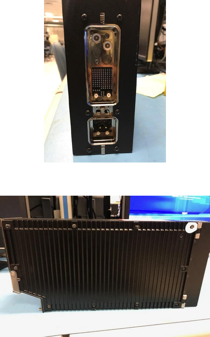
Figure 11 Unit Back Picture
Figure 12 Unit side Picture
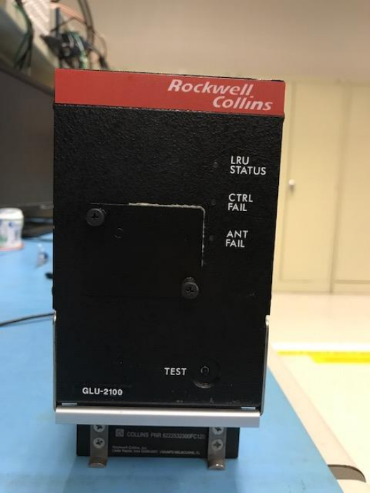
Figure 13 Unit Front Picture
FCC Part 15.19 Warning Statement- (Required for all Part 15 devices)
THIS DEVICE COMPLIES WITH PART 15 OF THE FCC RULES. OPERATION IS SUBJECT
TO THE
FOLLOWING TWO CONDITIONS: (1) THIS DEVICE MAY NOT CAUSE HARMFUL
INTERFERENCE,
AND (2) THIS DEVICE MUST ACCEPT ANY INTERFERENCE RECEIVED, INCLUDING
INTERFERENCE THAT MAY CAUSE UNDESIRED OPERATION.
FCC Part 15.21 Warning Statement-
NOTE: THE GRANTEE IS NOT RESPONSIBLE FOR ANY CHANGES OR MODIFICATIONS
NOT
EXPRESSLY APPROVED BY THE PARTY RESPONSIBLE FOR COMPLIANCE. SUCH
MODIFICATIONS COULD VOID THE USER’S AUTHORITY TO OPERATE THE EQUIPMENT.
NOTE: This equipment has been tested and found to comply with the limits for a
Class B digital device, pursuant to part 15 of the FCC Rules. These limits are
designed to provide reasonable protection against harmful interference in a
residential installation. This equipment generates uses and can radiate radio
frequency energy and, if not installed and used in accordance with the instructions,
may cause harmful interference to radio communications. However, there is no
guarantee that interference will not occur in a particular installation. If this equipment
does cause harmful interference to radio or television reception, which can be
determined by turning the equipment off and on, the user is encouraged to try to
correct the interference by one or more of the following measures:
- Reorient or relocate the receiving antenna.
- Increase the separation between the equipment and receiver.
-Connect the equipment into an outlet on a circuit different from that to which the
receiver is connected.
-Consult the dealer or an experienced radio/TV technician for help.