Rockwell Collins 8223132 Information Management System User Manual 946 03N1 001
Rockwell Collins Inc Information Management System 946 03N1 001
Manual

User Manual for Communication Certification of
the Information Management System
(IMS-6010)
Document Number 946-03N1-001
Revision
CAGE Code 0EFD0
Rockwell Collins
NAMETITLEAPPROVAL
PreparedBy:TannerS.ShephardPreparerN/A
ApprovedBy:AntoineF.Perez‐VernonProjectEngineerOnFile
ApprovedBy:PamelaM.CookDACEngineerOnFile
NOTICE:ThecontentsofthisdocumentareproprietarytoRockwellCollinsandshallnotbedisclosed,
disseminated,copied,orusedexceptforpurposesexpresslyauthorizedinwritingbyRockwellCollins.
Thetechnicaldatainthisdocument(orfile)iscontrolledforexportundertheExportAdministration
Regulations(EAR),15CFRParts730‐774.Violationsoftheseexportlawsmaybesubjecttofinesand
penaltiesundertheExportAdministrationAct.
©2015RockwellCollins.Allrightsreserved.
946-03N1-001 Rev -
Rockwell Collins Proprietary Information
Page 1
STATE 1 - DEVELOPMENT RELEASE 2015-04-22
-

Information Management
System
IMS-6010
User
Manual
This manual includes coverage of the following equipment:
U
nit
Model
Collins Part Number
Information Management
System
IMS-6010 822-3132-XXX
946-03N1-001 Rev -
Rockwell Collins Proprietary Information
Page 3
STATE 1 - DEVELOPMENT RELEASE 2015-04-22

ROCKWELL COLLINS,
INC.
INSTALLATION MANUAL
Export Control Classification Notice (ECCN) for this document is 7E994.
PROPRIETARY NOTICE
FREEDOM OF INFORMATION ACT (5 USC 552) AND DISCLOSURE OF CONFIDENTIAL INFORMATION
GENERALLY (18 USC
1905)
This document and the information disclosed herein are proprietary data of Rockwell Collins, Inc. Neither this
document nor the information contained herein shall be used, reproduced, or disclosed to others without the
written
authorization of Rockwell Collins, Inc., except to the extent required for installation or maintenance of
recipient’s equipment. This document is being furnished in confidence by Rockwell Collins, Inc. The
information
disclosed
herein falls within the exemption (b) (4) of 5 USC 552 and the prohibitions of 18 USC 1905.
SOFTWARE COPYRIGHT NOTICE
© COPYRIGHT 2015 ROCKWELL COLLINS, INC. ALL RIGHTS
RESERVED
All software resident in this equipment is protected by copyright.
We welcome your comments concerning this manual. Although every effort has been made to keep it free of
errors, some may occur. When reporting a specific problem, please describe it briefly and include the manual part
number, the paragraph or figure number, and the page number.
Send your comments to: Rockwell Collins,
Inc.
400 Collins Road NE, M/S
153-250
Cedar Rapids, IA 52498-0001
For product orders or inquiries, please contact: Rockwell Collins,
Inc.
Customer Response
Center
400 Collins Road NE, M/S 133-100
Cedar Rapids, IA 52498-0001
946-03N1-001 Rev -
Rockwell Collins Proprietary Information
Page 4
STATE 1 - DEVELOPMENT RELEASE 2015-04-22

946-03N1-001
i
TABLE OF
CONTENTS
Chapter/Para
Page
LIST OF ILLUSTRATIONS
...................................................................................
.iii
LIST OF TABLES
............................................................................................
.
iv
SAFETY
SUMMARY
.........................................................................................
v
1 General Information ..........................................................................................
1-1
1.1 INTRODUCTION. .................................................................................. 1-1
1.1.1 Equipment Covered. ................................................................................. 1-1
1.1.2 Equipment
Spec
ifications..............................................................................
1-1
1.1.3
Environmental Qualifications.
......................................................................... 1-2
1.2 PURPOSE OF
EQUIPMENT.
......................................................................... 1-3
1.3 EQUIPMENT OVERVIEW.
..........................................................................
1-4
1.3.1 Single Board Computer.
..............................................................................
1-4
1.3.2 Solid State Drive.
....................................................................................
1-4
1.3.3 Wireless LAN
Adapter.
............................................................................... 1-4
1.3.4 Power Supply
CCA...................................................................................
1-4
1.3.5 PC Base CCA........................................................................................ 1-4
1.3.6 802 Comm CCA.
....................................................................................
1-4
1.3.7 Interconnect CCA. ................................................................................... 1-4
1.3.8 Sim Board CCA. .................................................................................... 1-4
1.4 RELATED PUBLICATIONS.
.........................................................................
1-5
1.5 STORAGE.
.........................................................................................
1-5
2
Install
a
tion
..................................................................................................
2-1
2.1
GENERAL.
.........................................................................................2-1
2.2
UN
P
ACKING AND INSPECTING EQUIPMENT.
......................................................
2-1
2.3
PRE-INS
T
ALL
A
TION
CHECK........................................................................2-1
2.3.1
Cabling Precautions. .................................................................................2-1
2.4
PLANNING.
........................................................................................
2-2
2.4.1 Installation
Configu
r
ations.............................................................................
2-2
2.4.2
Strapping Options.
...................................................................................
2-2
2.4.3
Inpu
t
Powe
r
.
........................................................................................
2-2
2.4.4 Cooling Conside
r
ations. ..............................................................................2-2
2.5
CABLING INSTRUCTIONS.
.........................................................................
2-3
2.5.1 Parts Requi
r
ed. ......................................................................................2-3
2.5.2 Connec
t
o
r
In
f
o
r
mation.
...............................................................................2-3
2.5.3 Cable Shields and Ca
b
le Shield G
r
ounds................................................................2-4
2.6 CABLE ASSEMB
L
Y - CO
N
NECTOR J1 PI
N
S.......................................................... 2-4
2.7
CABLE ASSEMB
L
Y - CONNECTOR J2
PINS..........................................................
2-7
2.8 CABLE ASSEMB
L
Y - CO
N
NECTOR J3
PINS.........................................................
2-13
2.9
CABLE ASSEMB
L
Y - CONNECTOR J4 PIN (FUTURE GROWTH).
....................................
2-13
2.10
CABLE ASSEMB
L
Y - CONNECTOR J5
PINS.........................................................
2-13
2.11
CABLE ASSEMBLY - CONNECTOR J6
PINS.........................................................
2-13
2.12
INSTALL
A
TION
PROCEDURES.....................................................................
2-15
2.12.1 IMS-6010 Installation and Re
m
oval...................................................................2-15
2.13
TESTING.
.........................................................................................
2-16
3 Operation ................................................................................................... 3-1
3.1 OPERATION PROCEDURES.
........................................................................
3-1
3.1.1 Operating Procedures.
................................................................................
3-1
4 Theory of
Operation
..........................................................................................
4
-1
946-03N1-001 Rev -
Rockwell Collins Proprietary Information
Page 5
STATE 1 - DEVELOPMENT RELEASE 2015-04-22

946-03N1-001
ii
TABLE OF
CONTENTS
Chapter/Para
P
age
4.1
INTRODUCTION
TO THEORY OF OPERATION.
.....................................................
4-1
4.2 INFORMATION MANAGEMENT SYSTEM.
..........................................................
4-1
4.3 FUNCTIONAL DESCRIPTION.
......................................................................
4-1
4.4 SYSTEM INTERFACE.
..............................................................................
4-1
4.4.1 General Information for Connector J1 Signals.
..........................................................
4-1
5 Mai
n
tenance.................................................................................................
5-1
5.1 I
N
TRODUCTIO
N
TO MAI
N
TE
N
ANCE...............................................................5-1
5.2 TESTI
N
G
PROCEDURES.
...........................................................................5-1
5.2.1
Initial Powe
r
ON.
....................................................................................
5-1
5.2.2 Powe
r
-on Self Test.
..................................................................................
5-1
5.2.3
Ke
r
nel Sta
r
tup.
......................................................................................
5-1
5.2.4
Application S
t
ar
t
up.
..................................................................................
5-1
5.2.5
Additional Functional Checks..........................................................................5-1
5.3
SELF TEST.
........................................................................................
5-1
GLOSSARY ..............................................................................................
.Glossary-1
946-03N1-001 Rev -
Rockwell Collins Proprietary Information
Page 6
STATE 1 - DEVELOPMENT RELEASE 2015-04-22

946-03N1-001
iii
LIST OF
ILLUSTRATIONS
Number Title
P
age
1-1 IMS-6010
................................................................................................
1-1
2-1 IMS-6010 Configuration ...................................................................................
2-2
2-2 J1 Pin
Arrangement........................................................................................ 2-8
2-3 J2 Pin
Arrang
em
ent........................................................................................
2-9
2-4 RJ45 J6 Front Ethernet Indicator Lights .....................................................................
2-14
2-5 IMS-6010
Connectors..................................................................................... 2-16
946-03N1-001 Rev -
Rockwell Collins Proprietary Information
Page 7
STATE 1 - DEVELOPMENT RELEASE 2015-04-22

946-03N1-001
iv
LIST OF
TABLES
Number Title
P
age
1-1 IMS-6 010 Equi pment Specifications. ........................................................................
1-2
1-2 IMS-6010
Environmental Qualifications
Form.................................................................
1-2
1-3 IMS Major Components. ...................................................................................
1-4
1-4 Related Publications.
......................................................................................
1-5
2-1 IMS-6010 Mating Connector Hardware.......................................................................
2-3
2-2 Mating Cable Guidelines For
IMS-6010
......................................................................
2-4
2-3 J1 Connector Pin Functions.
................................................................................
2-5
2-4 J2 Connector Pin Functions. ...............................................................................
2-10
2-5 J3 Connector Pin Functions
................................................................................
2-13
2-6 J5 Connector Pin Functions. ...............................................................................
2-13
2-7 J6 Connector Pin Functions. ...............................................................................
2-15
4-1 Main Input Power Source...................................................................................
4-1
946-03N1-001 Rev -
Rockwell Collins Proprietary Information
Page 8
STATE 1 - DEVELOPMENT RELEASE 2015-04-22

946-03N1-001
v
SAFETY
SUMMARY
1. GENERAL ADVISORIES FOR ALL UNITS.
Service personnel are to obey standard safety precautions, such as wearing safety glasses, to prevent
personal
injury while installing or doing maintenance on this
unit.
Use care when using sealants, solvents and other chemical compounds. Do not expose to excessive heat or open
flame. Use only with
adequate
ventilation. Avoid
prolonged
breathing of vapors and avoid
prolonged
contact with
skin. Observe all cautions and warnings given by the
manufacturer.
Remove all power to the unit before disassembling it. Disassembling the unit with power connected is
dangerous
to life and may cause voltage transients that can damage the unit.
This unit may have components that contain materials (such as beryllium oxide, acids, lithium, radioactive
ma-
terial, mercury, etc) that can be hazardous to your health. If the component enclosure is broken, handle the com-
ponent in accordance with OSHA requirements 29CFR 1910.1000 or superseding documents to prevent
personal
contact with or inhalation of hazardous materials. Since it is virtually impossible to determine which components
do or do not contain such hazardous materials, do not open or disassemble components for any
reason.
This unit exhibits a high degree of functional reliability. Nevertheless, users must know that it is not practical
to
monitor for all conceivable system failures and, however unlikely, it is possible that erroneous operation could
oc-
cur without a fault indication. The pilot has the responsibility to find such an occurrence by means of
crosschecks
with redundant or correlated data available in the cockpit.
Before handling any unit or unit component, ground the repair operator through a conductive wrist strap or
other
device that uses a 470 kΩ or 1 MΩ series resistor to prevent operator injury.
946-03N1-001 Rev -
Rockwell Collins Proprietary Information
Page 9
STATE 1 - DEVELOPMENT RELEASE 2015-04-22

946-03N1-001
vi
Turn off power before disconnecting any unit from wiring. Disconnecting the unit without turning power off may cause
voltage
transients that can damage the
unit.
a. De-energize or remove all power, signal sources, and loads used with the unit.
b. Place the unit on a work surface that can conduct electricity (is grounded).
c. Ground the repair operator through a conductive wrist strap or other device using a 470 kΩ or 1 MΩ series resistor to prevent
operator injury.
d. Ground any tools (and soldering equipment) that will contact the unit. Contact with the operator's hand is a sufficient ground
for hand tools that are electrically
isolated.
e. All ESDS replacement components are shipped in conductive foam or tubes and must be stored in their shipping
containers
until installed.
f. ESDS devices and assemblies that are removed from a unit must immediately be put on the conductive work surface or in
conductive containers
.
g. Place repaired or disconnected circuit cards in aluminum foil or in plastic bags that have a layer of, or are made with,
conductive
material.
h. Do not touch ESDS
devices/assemblies
or remove them from their containers until they are needed.
946-03N1-001 Rev -
Rockwell Collins Proprietary Information
Page 10
STATE 1 - DEVELOPMENT RELEASE 2015-04-22
946-03N1-001
1-1
CHAPTER
1
General
Information
1.1. INTRODUCTION.
This installation manual provides information for the installation of the Information Management System (IMS-6010) in the
aircraft.
The Information Management System (IMS) is a standalone Line Replaceable Unit (LRU) that can be utilized in multiple
avionics
applications.
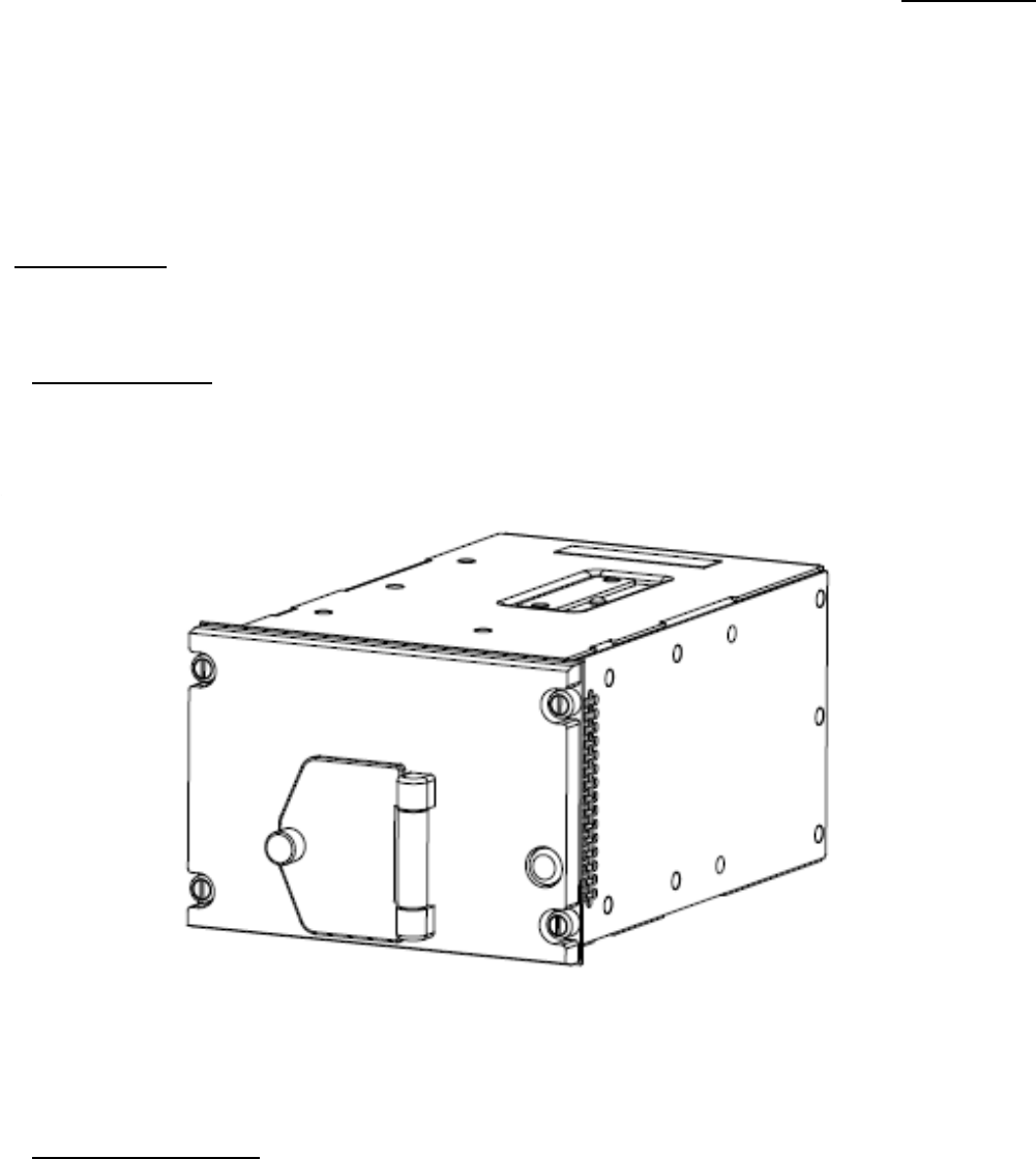
1.1.1. Equipment Covered.
The IMS-6010 is covered in this manual. The IMS-6010 is illustrated as such:
Figure 1-1. IMS-6010
1.1.2. Equipment Specifications.
Equipment
specifications,
physical
characteristics,
and power requirements for IMS-6010 are listed in Table 1-1.
946-03N1-001 Rev -
Rockwell Collins Proprietary Information
Page 11
STATE 1 - DEVELOPMENT RELEASE 2015-04-22

gene
r
al info
r
mation 946-03N1-001
1-2
Table 1-1. IMS-6010 Equipment
Speci
fi
cations.
CHARACTERISTIC
SPECIFICATION
Certification/Related
Documents:
Certification
RTCA Documents
Physical: Size:
Height
Width
Length
Weight
Cooling
Requirements
Electrical:
Power Requirements
Mounting
Information
Mating Connector
104.78 mm (4.125 in)
max.
146.05 mm (5.750 in)
max.
248.54 mm (9.785 in) max. (USB and Ethernet access door in closed
position)
1.79 kg (3.95 lb)
nominal
The IMS has both convectional cooling an internal fan which blows heated air
out of the unit.
Refer to the Installation chapter for mounting
information.
Refer to the Installation chapter for mating connector information.
1.1.3. Environmental Qualifications.
Environmental qualifications for the IMS-6010 are listed in Table
1-2.
Table 1-2. IMS-6010 Environmental Qualifications
Form.
CONDITIONS
DO-160G
SECTION
AND
REV
EQUIPMENT QUALIFICATIONS
CATEGORIES OF CONDUCTED TESTS
TEMPERATURE AND
ALTITUDE:
TEMPERATURE:
GROUND SURVIVAL
LOW
TEMP
OPERATING LOW
TEMP
GROUND SURVIVAL HIGH
TEMP
OPERATING HIGH
TEMP
IN FLIGHT LOSS OF
COOLING
ALTITUDE
4.0
4.5
4.5.1
4.5.2
4.5.3
4.5.4
4.5.5
4.6.1
A4
-55 °C (-67
°F)
-15 °C (+5
°F)
+85 °C (+185 °F)
+55 °C (+131
°F)
V. (30 Minute (+30 °C (+86 °F))
15, 000 ft
946-03N1-001 Rev -
Rockwell Collins Proprietary Information
Page 12
STATE 1 - DEVELOPMENT RELEASE 2015-04-22

gene
r
al info
r
mation 946-03N1-001
1-3
Table 1-2. IMS-6010 Environmental Qualifications Form. - Continued
CONDITIONS
DO-160G
SECTION
AND
REV
EQUIPMENT QUALIFICATIONS
CATEGORIES OF CONDUCTED
TESTS
DECOMPRESSIO
N
OVERPRESSURE
TEMPERATURE VARIATION
HUMIDITY
SHOCK:
OPERATIONAL
CRASH
SAFETY
VIBRATION
WATERPROOFNESS
FLUID SUSCEPTIBILITY
SAND AND
DUST
FUNGUS
RESISTANCE
SALT SPRAY
MAGNETIC
EFFECT
POWER
INPUT
VOLTAGE SPIKE
AUDIO FREQUENCY
SUSCEPTIBILITY
INDUCED SIGNAL
SUSCEPTIBILITY
RF
SUSCEPTIBILITY
EMISSION OF RF
ENERGY
LIGHTNING INDUCED TRANSIENT
SUSCEPTIBILITY
LIGHTNING DIRECT EFFECTS
ICING
ELECTROSTATIC
DISCHARGE
SUSCEPTIBIL-
ITY
FLAMMABILITY
4.6.2
4.6.3
5.0
6.0
7.0
7.2
7.3
8.0
9.0
10.0
11.0
12.0
13.0
14.0
15.0
16.0
17.0
18.0
19.0
20.0
21.0
22.0
23.0
24.0
25.0
26.0
50,000
ft
170 kPa
B. (5 °C per minute)
A. (48
hours)
B
Tested at 6-g (11 ms duration)
Impulse 20-g, sustained 20-g
(RBBI)(HR)(SM)
E
X
X
X
X
X
Z
B and
Z.
A
Z
CC
KR
M
(A3)(J3)3
X
X
A
X
1.2. PURPOSE OF EQUIPMENT.
Refer to Table 1-3 for a list of the units included in this manual.
946-03N1-001 Rev -
Rockwell Collins Proprietary Information
Page 13
STATE 1 - DEVELOPMENT RELEASE 2015-04-22

gene
r
al info
r
mation 946-03N1-001
1-4
1.3. EQUIPMENT OVERVIEW.
The IMS is Dzus-rail mounted LRU that provides a commercial data processing capability. The IMS is capable of
transferring
maintenance data between off-board commercial PC platforms and the aircraft cockpit. The IMS is used to run on-aircraft
software
packages that are hosted on the Windows 7 operating
system.
1.3.1. Single Board Computer.
The SBC provides core X86 processing functionality in a small plug-in module.
1.3.2. Solid State
Drive.
The Solid State Disk drive provides functionality equivalent to a PC spinning hard disk
drive.
1.3.3. Wireless LAN Adapter.
The
Wireless
LAN
Adapter provides
an
interface
to 802.11 b/g
wireless
networks.
1.3.4. Power Supply CCA.
The Power Supply CCA is a plug-in card assembly that mates with the Interconnect card. The Power Supply converts the 28 VDC
nominal power input to a regulated +5 VDC output for use by the other IMS modules. Included is a housekeeping supply and
monitors for temperature, voltage and current. Storage capacitors are charged with sufficient energy to allow the IMS to
continue
to play through 200 ms power interrupt.
1.3.5. PC Base CCA.
The PC Base CCA is a plug-in card assembly that mates with the Interconnect card. The PC Base CCA is a Baseboard for hosting
the Physical Layer I/O to support the ETX Computer Module. It provides Discrete I/O, one USB 2.0 port, one
Ethernet
Maintenance port, and a VGA Test port for use outside of the IMS cabinet. The PC Base CCA provides a PCI Bus, two IDE
channels, an I2C/SMBus, and an ISA Bus for use within the IMS
cabinet.
1.3.6. 802 Comm
CCA.
The 802 Comm CCA is a plug-in card assembly that mates with the Interconnect card. The 802 Comm CCA also mates directly
via
stacking connectors with the PC Base card. The 802 Comm CCA provides seven total Ethernet Ports out of the IMS cabinet; two
are dedicated for AFDX channels. The 802 Comm CCA provides 802.11b/g Wireless LAN functionality via a mini-PCI interface
to a purchased Wireless Adapter mini-PCI card, which is hosted on the 802
Comm.
1.3.7. Interconnect CCA.
The Interconnect CCA attaches via screws into the rear of the IMS chassis structure. The Interconnect CCA provides
interconnect
between the CCAs and the external connectors. The Interconnect CCA provides lightning protection for the power input. The
Interconnect CCA acts as a filter for signals and provides lightning protection for
them.
1.3.8. Sim Board CCA.
The Sim Card CCA is a plug-in card assembly that mates directly with a stacking connector on the Comm CCA. The Sim Board CCA
provides 4 SIM card slots for cellular function.
Table 1-3. IMS Major
Components.
Assembly
Part Number
Description
Single Board
Computer
Solid State Drive
Wireless LAN
Adapter
PC Base
CCA
802 Comm CCA
Power Supply
CCA
Interconnect
CCA
Sim Board CCA
270-3489-010
270-3499-020
270-3512-010
828-3845-103
828-3846-103
828-3844-103
828-3847-003
828-4292-001
Purchased
assembly.
Purchased assembly.
Purchased
assembly.
Manufactured circuit card
assembly.
Manufactured circuit card assembly.
Manufactured circuit card
assembly.
Manufactured circuit card assembly.
Manufactured circuit card assembly
946-03N1-001 Rev -
Rockwell Collins Proprietary Information
Page 14
STATE 1 - DEVELOPMENT RELEASE 2015-04-22

gene
r
al info
r
mation 946-03N1-001
1-5
1.4. RELATED
PUBLICATIONS.
Refer to Table 1-4 for a list of publications related to
IMS-6010.
Table 1-4. Related
Publications.
PUBLICATION
COLLINS PART NUMBER
Rockwell Collins Installation Practices
Manual
Rockwell Collins Bonding and Grounding Practices Manual
523-0775254
523-0776007
1.5. STORAGE.
The IMS-6010 should be stored in its original packing materials and shipping container. If the unit is to be stored for a long period
of time, put the unit in an airtight plastic bag with
sufficient
desiccant to absorb moisture. At no time should the
ambient
temperature
of the storage area fall below -55 °C (-67 °F) or rise above +85 °C (+185 °F). The relative humidity should never exceed 95
percent.
If the unit is stored for an extended period of time, retest the unit prior to returning it to service to ensure that possible component
degradation has not affected
performance.
946-03N1-001 Rev -
Rockwell Collins Proprietary Information
Page 15
STATE 1 - DEVELOPMENT RELEASE 2015-04-22

946-03N1-001
2-1
CHAPTER
2
Installation
2.1. GENERAL.
This chapter provides information for the installation of the Information Management System (IMS-6010). Procedures must
be
performed as described below to be sure of proper operation and
performance.
NOTE
The information and instructions provided in this chapter are recommendations and do not necessarily
correspond
with any actual aircraft installation and wiring. This chapter cannot be used in place of a Supplemental Type
Certificate (STC) or Type Certificate (
TC).
2.2. UNPACKING AND INSPECTING EQUIPMENT.
Unpack
the
equipment carefully
and make a
careful visual inspection
of the unit for
possible shipping
damage. All
claims
for damage
should be filed with the transportation company involved. If claims for damage are to be filed, save the original shipping container
and materials. If no damage can be detected, replace packing materials in the shipping container and save for future use (for
example,
storage or reshipment). Perform a visual inspection of the unit and inspect for the following concerns:
1. Look for any damage or corrosion.
2. Make sure all parts are intact and in working
order.
3. Check connectors J1, J2, J3, J5, and J6 for any damage, corrosion and broken or bent pins.
2.3. PRE-INSTALLATION CHECK.
Remove all electrical power to the equipment and/or equipment mounts before installing or removing
them
.
Prior to installation of unit in the aircraft, make sure the system or equipment that will interface with the IMS-6010 is
operating
properly and all applicable tests have been performed. Refer to the latest revision of the Component Maintenance Manual (
CMM)
or Illustrated Parts List (IPL) to perform testing of the unit. In the absence of the CMM/IPL, the Acceptance Test Procedure for the
panel variant will be used to perform testing of the unit.
2.3.1. Cabling Precautions.
Observe the following precautions during the preparation of the interconnect wiring cables:
• Bond and shield all parts of the aircraft electrical system such as generators and ignition
systems.
• Keep connecting cables away from heavy current carrying circuits, pulse transmitting equipment, and interference
sources.
• Make all external connections to the system equipment through the designated connector J1, Figure 2-2 and connector J2, and
Figure 2-3 and connector J3. The required hardware and connector are supplied if
s
peci
fi
ed.
• Suitable wire should be used in accordance with applicable specifications.
• Leave slack in cable to allow free movement of equipment, keeping wires from
breaking.
946-03N1-001 Rev -
Rockwell Collins Proprietary Information
Page 16
STATE 1 - DEVELOPMENT RELEASE 2015-04-22
946-03N1-001
2-2
2.4. PLANNING.
Proper and careful planning prior to installation is essential for reliable performance and easy maintenance. The list that follows
is
a sample of the points to be considered in planning an
installation:
1. Installation location. Allow for adequate airflow for cooling, good bonding to aircraft ground, ease of cable routing, room for
single/dual/triple
mounting in a location that provides structural rigidity.
2. Installation
con
fi
guration.
3. Compatibility with other equipment and loading considerations.
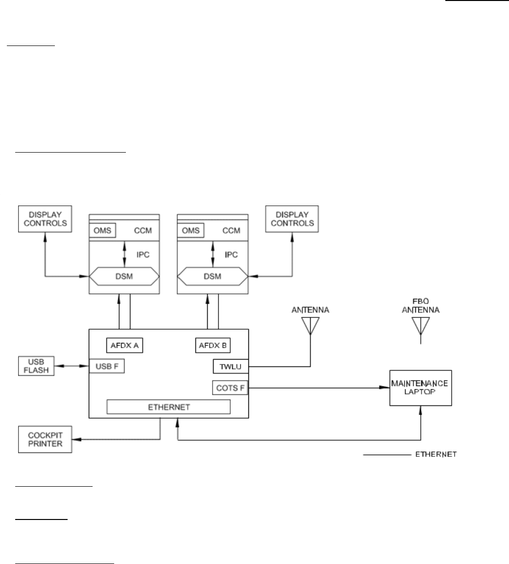
2.4.1. Installation Configurations.
The
complete configuration
is
dependent
of the
desired connections
to
ancillary
equipment. Figure 2-1 shows a
typical
configuration:
Figure 2.1. IMS-6010 Configuration
2.4.2. Strapping Options.
There are no strapping requirements for the IMS-6010.
2.4.3. Input
Power.
All power required by the IMS-6010 is provided by the aircraft in which the system is installed. The IMS-6010 requires an input of
+28 V dc at 55 watts (max) of power for normal operation.
2.4.4. Cooling Considerations.
For IMS-6010 environmental
qualification
refer to Chapter 1, General Information.
2.4.4.1. Units tightly packed on the equipment rack heat each other through radiation, convection, and sometimes by direct con-
duction. If space permits, separate the units from each other to significantly improve
reliability.
946-03N1-001 Rev -
Rockwell Collins Proprietary Information
Page 17
STATE 1 - DEVELOPMENT RELEASE 2015-04-22

installation 946-03N1-001
2-3
2.4.4.2. Even a single unit operates at a much higher temperature in still air than in moving air. Fans, or some other means
of
moving the air around electronic equipment, are usually a worthwhile investment. If a form of ram air cooling is installed,
make
certain that rainwater cannot enter and be sprayed on the equipment.
2.5. CABLING INSTRUCTIONS.
Make sure that the aircraft battery master switch is turned off before installing any of the interconnect cabling.
Failure to do so could cause electrical arcing that might result in damage to the equipment or serious injury
to
maintenance personnel.
Interconnect cables should be prepared in accordance with the
interconnect
diagrams which are part of approved
supplemental
type
certificate data packages.
2.5.1. Parts Required.
Table 2-1 lists the mating connectors, strain reliefs and contacts required to install the
IMS-6010.
Table 2-1. IMS-6010 Mating Connector
Hardware.
REF
DES
LRU CONNECTOR MATING
CONNECTOR
BACKSHELL/STRAIN
RELIEF
DESCRIPTION
CPN MIL
VENDOR PN
CPN MIL
VENDOR PN
CPN MIL
VENDOR PN
J1
J2
J3
J4
J5
J6
D38999/20FG35AN
D38999/20FG35AN
D38999/20FG35AA
D38999/20FG35AA
357-7347-010
M39012/28-0018
268-0013-110
RJ-45
JACK
360-0417-010
USB TYPE
A
D38999/26FG35SN
D38999/26FG35SN
D38999/26FG35SA
D38999/26FG35SA
M39012/26-0011
M39012/26-0011
RJ-45
PLUG
USB
PLUG
GLENAIR
400HS001M2107L3
or
equivalent
859-6619-160
or
equivalent
79 PIN SERIES FOR
ETHERNET
79 PIN SERIES
FOR
SIGNAL AND
POWER
TNC WLAN 1, MATE IS
PLUG FOR RG-400
FRONT PANEL
RJ-45
FRONT PANEL
USB
2.5.2. Connector Information.
2.5.2.1. During preparation of the interconnect cables, observe the precautions that
follow:
• Read all notes on the drawings and interconnect diagrams prior to fabricating interconnect wiring cables.
• Bond and shield all parts of the aircraft electrical system, for example, generator and ignition systems.
• Keep the interconnect cables away from circuits carrying heavy current, pulse transmitting equipment, and other sources of
in-
terference.
• Make all external connections of the equipment through the designated connectors listed on the outline and mounting diagrams.
946-03N1-001 Rev -
Rockwell Collins Proprietary Information
Page 18
STATE 1 - DEVELOPMENT RELEASE 2015-04-22

installation 946-03N1-001
2-4
• For balanced connections, use twisted-pair shielded wiring for minimum pickup of electrostatic and magnetic fields. Avoid
long
runs of wire and keep input and output circuits separated as much as
possible.
• All
interconnect
wires and cables should be marked in
accordance
with the Aircraft
Electronics Association
(AEA) WireMarking
Standard.
• Avoid excessive cable lengths, but allow sufficient slack for movement due to
vibration.
• After installation of the cables in the aircraft, and before installation of the equipment, check to make sure that aircraft power
is
applied only to the pins
specified
on the interconnect diagrams and that all other wires and shields are properly terminated.
2.5.3. Cable Shields and Cable Shield Grounds.
All wiring and component selections must follow the
specification
FAA AC43.13-1B and the accepted procedures of the industry.
1. Connect the unit primary DC power-return circuit and chassis ground (if used) to the different ground points in the aircraft. Do
not connect these two circuits together at their ground points. Make each wire as short as possible, do not make more than
1
meter (39.37 inches). All power (high) wiring must be a
minimum
of AWG 22 with the power (ground) wiring AWG 20 unless
differently
not
ed.
2. Connect to ground the two ends of the cable that have an external shield unless shown
differently.
3. Connect all the cable shields to ground at one ground-point for each, unless shown differently. If the connector backshell is
of
a
metal conductor material and a low impedance bond is made, connect the cable shield to the connector backshell and keep
the shields internal to the connector
backshell.
4. Connect the cable shield to related pins in the connector when a low-impedance bond is not made to the connector
backshell.
Alternate scheme gives less shielding and the performance is substantially decreased at the radar and higher
frequencies.
Table 2-2. Mating Cable Guidelines For
IMS-6010
Signal type
Ethernet
USB
Discrete
Audio
input
RF
+28VDC &
28VDC_RTN
Cable type
Tensolite NF24Q100
or
equivalent
Tensolite NF24Q100
or
equivalent
22 gauge or equivalent
Twisted, shielded
pair,
24 gauge or
equivalent
RG400 coaxial or
equivalent
22 gauge or equivalent
Max cable length
73
m
5
m
20 ft
Shield config
Integral shield, ties
to
backshell
N/A
Gnd/Rtn
N/A
Dedicated power
return
Referenced to common
signal ground
Dedicated power return
2.6. CABLE ASSEMBLY - CONNECTOR J1 PINS.
NOTE
Different cable assemblies may not be required depending on aircraft configuration.
For additional information during the cable assembly and the system overview for the unit interface being used refer to Figure
2-2,
Figure 2-4, and Table 2-3 for Connector
J1.
946-03N1-001 Rev -
Rockwell Collins Proprietary Information
Page 19
STATE 1 - DEVELOPMENT RELEASE 2015-04-22

installation 946-03N1-001
2-5
Table 2-3. J1 Connector Pin
Functions.
PIN
FUNCTION
CONNECTION
TYPE
1
2
3
4
5
6
7
8
9
10
11
12
13
14
15
16
17
18
19
20
21
22
23
24
25
26
27
28
29
AFDX CHANNEL A ETHERNET PORT TRANSMIT
HIGH
AFDX CHANNEL A ETHERNET PORT TRANSMIT
LOW
RESERVED
AFDX CHANNEL A ETHERNET PORT RECEIVE
HIGH
AFDX CHANNEL A ETHERNET PORT RECEIVE
LOW
RESERVED
USB PORT 1 DATA
HIGH
USB PORT 1 DATA
LOW
RESERVED
USB PORT 1 +5 VDC POWER (500 ma
max)
USB PORT 1 POWER
RETURN
RESERVED
AFDX CHANNEL B ETHERNET PORT
TRANSMIT
HIGH
AFDX CHANNELl B ETHERNET PORT
TRANSMIT
Low
RESERVED
AFDX CHANNEL B ETHERNET PORT
RECEIVE
HIGH
AFDX CHANNEL B ETHERNET PORT
RECEIVE
LOW
RESERVED
ETHERNET PORT 1 TRANSMIT
HIGH
ETHERNET PORT 1 TRANSMIT
LOW
RESERVED
ETHERNET PORT 1 RECEIVE
HIGH
ETHERNET PORT 1 RECEIVE
LOW
RESERVED
ETHERNET PORT 2 RECEIVE
HIGH
RESERVED
ETHERNET PORT 2 TRANSMIT
HIGH
RESERVED
RESERVED
No
connection
Power
No connection
No connection
No
connection
No connection
No connection
No
connect
io
n
No
connection
No connection
Output
Output
Input
Input
Input/Output
Input/Output
Output
Output
Output
Input
Input
Output
Output
Input
Input
Input
Output
946-03N1-001 Rev -
Rockwell Collins Proprietary Information
Page 20
STATE 1 - DEVELOPMENT RELEASE 2015-04-22

installation 946-03N1-001
2-6
Table 2-3. J1 Connector Pin Functions. - Continued
PIN
FUNCTION
CONNECTION
TYPE
30
31
32
33
34
35
36
37
38
39
40
41
42
43
44
45
46
47
48
49
50
51
52
53
54
55
56
57
58
59
60
61
62
63
RESERVED
RESERVED
RESERVED
RESERVED
RESERVED
RESERVED
RESERVED
RESERVED
RESERVED
RESERVED
RESERVED
RESERVED
RESERVED
RESERVED
RESERVED
RESERVED
RESERVED
RESERVED
ETHERNET PORT 2 RECEIVE
LOW
RESERVED
ETHERNET PORT 2 TRANSMIT LOW
RESERVED
ETHERNET PORT 3 TRANSMIT HIGH
ETHERNET PORT 3 TRANSMIT LOW
RESERVED
ETHERNET PORT 3 RECEIVE
HIGH
ETHERNET PORT 3 RECEIVE
LOW
RESERVED
ETHERNET PORT 4 TRANSMIT
HIGH
ETHERNET PORT 4 TRANSMIT
LOW
RESERVED
ETHERNET PORT 4 RECEIVE
HIGH
ETHERNET PORT 4 RECEIVE
LOW
RESERVED
No
connection
No
connection
No connection
No
connection
No
connection
No connection
No
connection
No
connection
No connection
No
connection
No connection
No connection
No
connection
No connection
No connection
No
connection
No connection
No connection
No connection
No connection
No connection
No connection
No connection
No
connection
Input
Output
Output
Output
Input
Input
Output
Output
Input
Input
946-03N1-001 Rev -
Rockwell Collins Proprietary Information
Page 21
STATE 1 - DEVELOPMENT RELEASE 2015-04-22

installation 946-03N1-001
2-7
Table 2-3. J1 Connector Pin Functions. - Continued
PIN
FUNCTION
CONNECTION
TYPE
64
65
66
67
68
69
70
71
72
73
74
75
76
77
78
79
ETHERNET PORT 5 TRANSMIT HIGH
RESERVED
RESERVED
RESERVED
RESERVED
RESERVED
RESERVED
RESERVED
RESERVED
RESERVED
RESERVED
ETHERNET PORT 5 TRANSMIT
LOW
RESERVED
ETHERNET PORT 5 RECEIVE HIGH
ETHERNET PORT 5 RECEIVE
LOW
RESERVED
No
connection
No connection
No
connection
No
connection
No connection
No
connection
No
connection
No connection
No
connection
No connection
No
connection
No
connection
Output
Output
Input
Input
2.7. CABLE ASSEMBLY - CONNECTOR J2 PINS.
NOTE
Different cable assemblies may not be required depending on aircraft
con
fi
guration.
For additional information during the cable assembly and the system overview for the unit interface being
used
refer to Figure 2-2, Figure 2-3, and Table 2-4 for Connector
J2.
DC
resistance
needs to be 2.5
milli-Ohms maximum
between the rear connector shell and the
mounting
surface(s)
where applicable in Figure 2-5 and Figure 2-6. Refer to 523-0775254 Installation Practices Manual and
523-
0776007 Bonding and Grounding Practices.
946-03N1-001 Rev -
Rockwell Collins Proprietary Information
Page 22
STATE 1 - DEVELOPMENT RELEASE 2015-04-22
installation 946-03N1-001
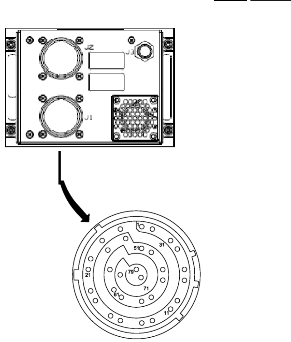
2-8
Figure 2-2. Jl Pin
Arrangement
TPJ4344_01
946-03N1-001 Rev -
Rockwell Collins Proprietary Information
Page 23
STATE 1 - DEVELOPMENT RELEASE 2015-04-22
installation 946-03N1-001
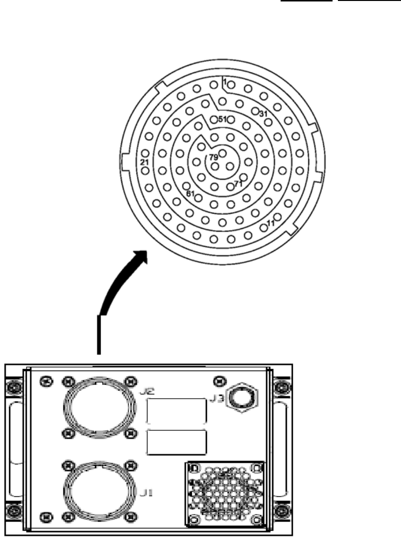
2-9
Figure 2-3. J2 Pin
Arrangement
TPJ4345_01
946-03N1-001 Rev -
Rockwell Collins Proprietary Information
Page 24
STATE 1 - DEVELOPMENT RELEASE 2015-04-22

installation 946-03N1-001
2-10
Table 2-4. J2 Connector Pin
Functions.
PIN
FUNCTION
CONNECTION
TYPE
1
2
3
4
5
6
7
8
9
10
11
12
13
14
15
16
17
18
19
20
21
22
23
24
25
26
27
28
29
30
31
32
33
AUDIO IN LEFT HIGH
GROUND
AUDIO OUT
LEFT
GROUND
VGA VIDEO
RED
VGA VIDEO
GREEN
VGA VIDEO BLUE
VGA
GROUND
VGA HORIZONTAL
SYNC
VGA SYNC
GROUND
VGA VERTICAL
SYNC
VGA SERIAL Clock
CHASSIS
GROUND
CHASSIS
GROUND
CHASSIS GROUND
CHASSIS
GROUND
SPARE
+28 VDC PRIMARY POWER INPUT
+28 VDC PRIMARY POWER
INPUT
28 VDC POWER
Return
28 VDC POWER Return
SPARE
ARINC 429 PORT 2 RECEIVE HIGH
SERIAL RS-422 PORT 1
TRANSMIT
HIGH
SERIAL RS-422 PORT 1
TRANSMIT
LOW
SPARE
GROUND
AUDIO IN Left
Low
AUDIO IN RIGHT
HIGH
SPARE
AUDIO OUT
RIGHT
VGA RED GROUND
VGA GREEN
GROUND
Reserved/No
connection
Ground
Reserved/No
connection
Ground
No connect
POWER
POWER
Ground
Ground
No
connection
Not implemented/Reserved
Not
implemented/Reserved
Not
implemented/Reserved
No
connection
Ground
Reserved/No
connection
Reserved/No
connection
No connection
Reserved/No
connection
Input
Output
Output
Output
Output
Output
Output
Output
Output
Input
Input
Input
Output
Output
Input
Input
Output
Output
Output
946-03N1-001 Rev -
Rockwell Collins Proprietary Information
Page 25
STATE 1 - DEVELOPMENT RELEASE 2015-04-22

installation 946-03N1-001
2-11
Table 2-4. J2 Connector Pin Functions. - Continued
PIN
FUNCTION
CONNECTION
TYPE
34
35
36
37
38
39
40
41
42
43
44
45
46
47
48
49
50
51
52
53
54
55
56
57
VGA BLUE
GROUN
D
VGA
RESERVED
VGA +5 VDC
SPARE
VGA SERIAL
DATA
DISCRETE IN 1, GENERAL
PURPOSE (user
de
fi
ned)
DISCRETE IN 2, GENERAL
PURPOSE (user
de
fi
ned)
DISCRETE IN 3,
GENERAL
PURPOSE (user defined)
DISCRETE IN, WEIGHT
ON
WHEELS, ACTIVE LOW
(dedicated)
DISCRETE OUT 1,
GENERAL
PURPOSE (user
de
fi
ned)
DISCRETE OUT 2, GENERAL
PURPOSE (user defined)
DISCRETE OUT 3,
GENERAL
PURPOSE (user
de
fi
ned)
DISCRETE OUT 4,
GENERAL
PURPOSE (user
de
fi
ned)
ARINC 429 PORT 2 RECEIVE LOW
SERIAL RS-422 PORT 1
RECEIVE
HIGH
SERIAL RS-422 PORT 1 RECEIVE
LOW
AUDIO IN RIGHT
LOW
SERIAL RS-422 PORT 2
RECEIVE
HIGH
SERIAL RS-422 PORT 2
RECEIVE
LOW
SPARE
TEST DISCRETE IN 1,
FACTORY
RESET
LOW
TEST DISCRETE IN 2,
FACTORY
RESET
L
OW
SERIAL RS-232 PORT 1
RECEIVE
GROUND
No
connection
Not implemented/Reserved
Not
implemented/Reserved
Not implemented/Reserved
Not implemented/Reserved
Not
implemented/Reserved
Not
implemented/Reserved
No connection
Not implemented/Reserved
Ground
Output
Output
Output
Output
Input
Input
Input
Input
Output
Output
Output
Output
Input
Input
Input
Input
Input
Input
Input
Input
Input
946-03N1-001 Rev -
Rockwell Collins Proprietary Information
Page 26
STATE 1 - DEVELOPMENT RELEASE 2015-04-22

installation 946-03N1-001
2-12
Table 2-4. J2 Connector Pin Functions. - Continued
PIN
FUNCTION
CONNECTION
TYPE
58
59
60
61
62
63
64
65
66
67
68
69
70
71
72
73
74
75
76
77
78
79
SERIAL RS-232 PORT 1 TRANSMIT
GROUND
GROUND
ARINC 429 PORT 1 TRANSMIT
HIGH
ARINC 429 PORT 1
TRANSMIT
LOW
ARINC 429 PORT 1 RECEIVE HIGH
ARINC 429 PORT 1 RECEIVE LOW
SERIAL RS-422 PORT 2
TRANSMIT
HIGH
SERIAL RS-422 PORT 2
TRANSMIT
LOW
SERIAL RS-422 PORT 4
TRANSMIT
LOW
SPARE
TEST DISCRETE IN 3,
WATCHDOG
DISABLE
LOW
TEST DISCRETE IN
4
GROUND
SERIAL RS-422 PORT 3 TRANSMIT
HIGH
SERIAL RS-422 PORT 3
TRANSMIT
LOW
SERIAL RS-422 PORT 3 RECEIVE
HIGH
SERIAL RS-422 PORT 3
RECEIVE
LOW
SERIAL RS-422 PORT 4
TRANSMIT
HIGH
SERIAL RS-422 PORT 4
RECEIVE
HIGH
SERIAL RS-422 PORT 4
RECEIVE
LOW
GROUN
D
Not implemented/Reserved
Ground
Ground
Not
implement
ed/Reserved
Not
implemented/Reserved
Not implemented/Reserved
Not
implemen
ted/Reserved
Not
implemented/Reserved
Not
implemented/Reserved
Not
implemented/Reserved
No connection
Ground
Not implemented/Reserved
Not
implemented/Reserved
Not implemented/Reserved
Not
implemented/Reserved
Not
impl
emented/Reserved
Not
implemented/Reserved
Not
implemented/Reserved
Groun
d
Output
Output
Output
Input
Input
Output
Output
Output
Input
Input
Output
Output
Input
Input
Output
Input
Input
946-03N1-001 Rev -
Rockwell Collins Proprietary Information
Page 27
STATE 1 - DEVELOPMENT RELEASE 2015-04-22

installation 946-03N1-001
2-13
2.8. CABLE ASSEMBLY - CONNECTOR J3 PINS.
NOTE
Antenna coax cable should be no more than 4.7 dB, which equates to approximately 20 feet of RG 400 cable.
Table 2-5. J3 Connector Pin
Functions
PIN
FUNCTION
CONNECTION
TYPE
Center
Shield
2.4 GHz RF for
WL
AN
GROUND
Ground
Input/Output
GND
2.9. CABLE ASSEMBLY - CONNECTOR J4 PIN (FUTURE GROWTH).
J4 is not installed in the baseline
design.
NOTE
The purpose of dual RF connections is to support spatial diversity reception. The J4 connector shall provide a Radio
Frequency
interface for the 2.4 GHz wireless LAN function.
2.10. CABLE ASSEMBLY - CONNECTOR J5 PINS.
The J5 connector provides a USB interface. Table 2-5 provides the connector signal definition. The J5 connector is Samtec
USB-
AM-S-F-B-SM1, CPN 360-0417-050, (USB Type A).
Table 2-6. J5 Connector Pin
Functions.
PIN
FUNCTION
CONNECTION
TYPE
1
2
3
4
USB PORT 2 +5VDC POWER, 500
MA
CAPABLE
USB PORT 2 DATA LOW
USB PORT 2 DATA
HIGH
USB PORT 2
GROUND
POWER
GROUND
Output
Input/Output
Input/Output
GND
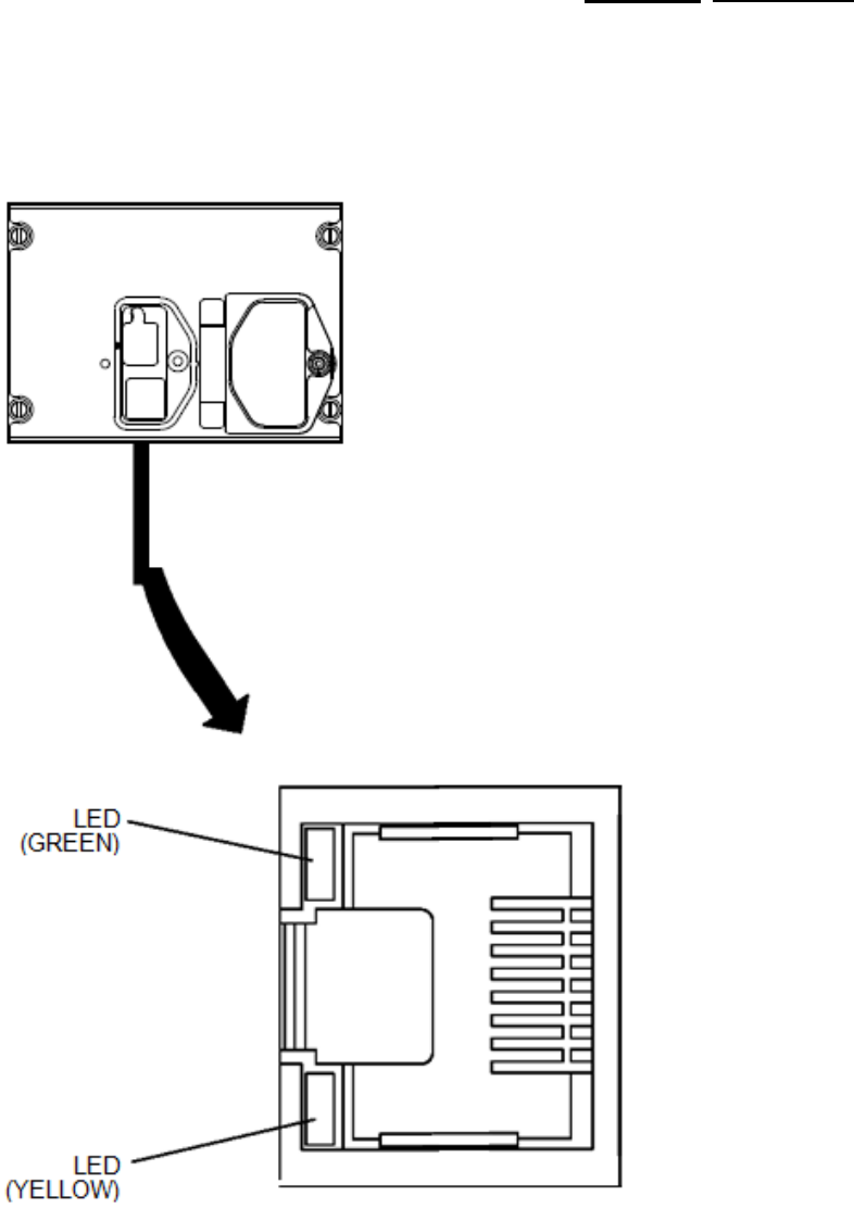
2.11. CABLE ASSEMBLY - CONNECTOR J6 PINS.
The J6 connector provides an Ethernet LAN interface. Table 2-6 provides the connector signal definition. The J6 connector is CPN
358-0042-010 (RJ45 jack).
946-03N1-001 Rev -
Rockwell Collins Proprietary Information
Page 28
STATE 1 - DEVELOPMENT RELEASE 2015-04-22
installation 946-03N1-001
2-14
Figure 2-4. RJ45 J6 Front
Ethernet Indicator Lights
946-03N1-001 Rev -
Rockwell Collins Proprietary Information
Page 29
STATE 1 - DEVELOPMENT RELEASE 2015-04-22

installation 946-03N1-001
2-15
Table 2-7. J6 Connector Pin
Functions.
PIN
FUNCTION
CONNECTION
TYPE
1
2
3
4
5
6
7
8
Ethernet port 6 Receive High
Ethernet port 6 Receive Low
Ethernet port 6 Transmit
High
Ethernet port 6 Transmit
Low
No connection
No
connectio
n
No connection
No
connection
Input
Input
Output
Output
2.12. INSTALLATION PROCEDURES.
This section contains procedures for installing the IMS-6010 in the aircraft. Procedures must be performed as described below to
ensure proper operation and
performance.
2.12.1. IMS-6010 Installation and Removal.
Make sure that the aircraft battery master switch is turned off before installing any equipment, mounts, or
intercon-
nect cables. Failure to do so could cause electrical arcing that might result in damage to the equipment or serious
injury to maintenance
personnel.
Select the desired location for the unit.
2.12.1.1. To install the IMS-6010, perform the steps that follow:
1. Remove electrical power from the
aircraft.
2. Make the appropriate cutout (if
required).
3. Pull the mating connector assemblies J1, J2, and J3 through the cutout hole.
4. Remove connector covers from mating
connectors.
5. Connect P1 to J1 on IMS-6010.
6. Connect P2 to J2 on IMS-6010.
7. Connect P3 to J3 on
IMS-6010.
8. Make sure the locking devices are secure to the connectors J1, J2, and J3.
9. Install the unit in the cutout until
fl
ush.
10. Tighten the four Dzus fasteners to secure IMS-6010 in place.
946-03N1-001 Rev -
Rockwell Collins Proprietary Information
Page 30
STATE 1 - DEVELOPMENT RELEASE 2015-04-22

installation 946-03N1-001
2-16
2.12.1.2. To remove the IMS-6010, perform the steps that follow:
1. Remove electrical power from the
aircraft.
2. Loosen the four Dzus fasteners that secure the IMS-6010 in
place.
3. Remove the unit from the cutout until clear of mounting surface.
4. Loosen locking device on connector
J1.
5. Loosen locking device on connector
J2.
6. Loosen locking device on connector J3.
7. Disconnect P3 from J3 on
IMS-6010.
8. Disconnect P2 from J2 on
IMS-6010.
9. Disconnect P1 from J1 on
IMS-6010.
10. If immediately installing a replacement IMS-6010, go to IMS-6010 Installation. If not immediately installing a replacement
IMS-6010, go to step
9.
11. Install dust cover on connector J1 to prevent damage to pins.
12. Install dust cover on connector J2 to prevent damage to
pins.
13. Install dust cover on connector J3 to prevent damage to pins.
14. Secure J1, J2, and J3 connectors with tie wraps to cables to prevent damage to connectors and other
intelligence.
2.13. TESTING.
Refer to the Maintenance chapter for test procedures for the
IMS-6010.
946-03N1-001 Rev -
Rockwell Collins Proprietary Information
Page 31
STATE 1 - DEVELOPMENT RELEASE 2015-04-22

946-03N1-001
3-1
CHAPTER
3
Operation
3.1. OPERATION PROCEDURES.
The IMS-6010 provides the capability for the technician to acquire maintenance data for each LRU for troubleshooting
purposes.
The DDS software, which is a component of the software load on the IMS-6010, provides the ability to retrieve System Event
log
files to determine the function of the operating system and the associated DDS applications on the
device.
3.1.1. Operating Procedures.
For instruction on how to operate the IMS-6010, go to the M145 Avionics System Operators Guide (CPN 523-0808930).
946-03N1-001 Rev -
Rockwell Collins Proprietary Information
Page 32
STATE 1 - DEVELOPMENT RELEASE 2015-04-22

946-03N1-001
4-1
CHAPTER
4
Theory of
Operation
4.1. INTRODUCTION TO THEORY OF OPERATION.
This chapter presents the Theory of Operation for the IMS-6010. The Theory of Operation is presented in an overview of the
entire
system and as functional theory for the system
unit.
4.2. INFORMATION MANAGEMENT SYSTEM.
The IMS-6010
contains
the software and
hardware
to
monitor
and
control
the user and
equipment interfaces
while being the platform
from which applications operate. The IMS transfers
maintenance
data between off-board commercial PC platforms and the aircraft
cockpit. The IMS runs on-aircraft software packages that are hosted on the Windows XP operating system.
4.3. FUNCTIONAL DESCRIPTION.
The IMS utilizes three purchased commercial-off-the-shelf (COTS) modules for its core functionality; a Single Board Com-
puter (SBC), a Solid State Drive (SSD), and a Wireless LAN Adapter (WLA). Three plug-in circuit card assemblies (CCAs)
provide further functions: the Power Supply CCA, the PC Base CCA and the 802 Comm CCA. The Interconnect CCA acts as
backplane for the
LRU.
4.4. SYSTEM
INTERFACE.
The IMS provides a link to the avionics system via two non-redundant AFDX Ethernet channels. Other Ethernet interfaces
allow
for maintenance connection points around the aircraft, and interface to printer.
The following input/output signals are located on the rear connectors J1 and J2 of the unit. All output control signals are capable
of
sinking 100 mA (Maximum), unless otherwise noted.
Front panel connectors on the IMS allow for an operator to insert a commercial USB memory stick into the unit, or to connect a
laptop computer via RJ45 jack. Remote Ethernet connection points may be implemented in the aircraft, which will allow
dataload
or maintenance access. The WLA and external antenna provide 802.11 wireless LAN function for maintenance access.
4.4.1. General Information for Connector J1 Signals.
The pins in connector J1 (X) are spare and are reserved in function. They are not connected in the IMS-6010.
Table 4-1. Main Input Power
Source.
INPUT
SPECIFICATION
VALUE
Nominal Input Voltage
Maximum Continuous Input
Voltage
Minimum Continuous Input
Voltage
Maximum Surge Voltage - 100 ms
Maximum Surge Voltage - 1
sec
Power Consumption
(Max)
28.0 V dc
30.3 V dc
22.0 V
dc
47.5 V dc
55
Watts
946-03N1-001 Rev -
Rockwell Collins Proprietary Information
Page 33
STATE 1 - DEVELOPMENT RELEASE 2015-04-22

946-03N1-001
5-1
CHAPTER
5
Maintenance
5.1. INTRODUCTION TO MAINTENANCE.
This chapter provides the procedures for the post-installation check of the Information Management System (IMS-6010) in
the
aircraft.
5.2. TESTING PROCEDURES.
Procedures provided herein are oriented for the IMS-6010. Interfacing equipment will need to be
verified
for their correct operation
using test procedures from the related manufacturers.
5.2.1. Initial Power ON.
On each power-up of the unit, the boot loader
initializes
the
hardware, performs
a power-on self test sequence, and the kernel startup
followed by the application software.
5.2.2. Power-on Self Test.
After the initialization of the hardware, the power-on self test is performed by the boot loader. Selective test of the RAM space and
an OS image CRC check is performed. Successful test continues by the boot loader to the kernel startup.
5.2.3. Kernel Startup.
During the kernel startup, the USB status LED
located
on the front panel is
YELLOW, indicating
the
successful completion
followed
by the application
startup.
5.2.4. Application Startup.
During the application startup, the USB status LED located on the front panel is GREEN, indicating the successful completion
followed by the USB port
readiness.
5.2.5. Additional Functional Checks.
After the
installation
of the IMS-6010 in the aircraft, make sure the equipment that interfaces with the unit is energized. Refer to the
last revision of the IMS CMM to do the Return-To-Service (RTS) test if there is a problem with the unit. Use the latest revision
of
the Acceptance Test Procedure to do the test if there is no CMM to
use.
5.3. SELF TEST.
The IMS supports self-test functions. These are implemented through IMS software programs. The IMS hardware shall provide
features that facilitate the self test
functions:
• Power on self test functions of Single Board Computer (SBC).
• Self diagnostic functions of Single State Device
(SSD).
• Self diagnostic functions of
WLA.
• Regulated power voltage monitoring for over & under voltage.
• Temperature monitoring for over and under operating
temperature.
• Non-volatile memory in SSD to store fault data.
946-03N1-001 Rev -
Rockwell Collins Proprietary Information
Page 34
STATE 1 - DEVELOPMENT RELEASE 2015-04-22

946-03N1-001
Glossary-1/(Glossary-2
Blank)
GLOSSARY
Term
De
fi
nition
AEA Aircraft Electronics
Association
AFDX Avionics Full Duplex Switched
Ethernet
AFIS Airborne Flight Information System
ARINC Aeronautical Radio, Incorporated
CCA Circuit Card Assembly
CDU Control Display Unit
CPN Collins Part Number
DBU Data Base Unit
DMU Data Management Unit
ETX Embedded Technology eXtended
FADEC Full Authority Digital Engine Control
FMC Flight Management Computer
FMS Flight Management System
FSU File Server
Unit
IFIS Integrated Flight Information System
LAN Local Area Network
LED Light Emitting
Diode
LRU Line Replaceable
Unit
MCDU Multifunction Control Display
Unit
MDC Maintenance Diagnostic
Computer
MFD Multifunction
Display
MTBF Mean Time Between Failure
N/A Not
Applicable
RT S R e t u r n To
Service
STC Supplemental Type
Certi
fi
cate
TC Type Certificate
USB Universal Serial
Bus
WLA Wireless LAN
Adapter
946-03N1-001 Rev -
Rockwell Collins Proprietary Information
Page 35
STATE 1 - DEVELOPMENT RELEASE 2015-04-22

946-03N1-001
Glossary-1/(Glossary-2
Blank)
946-03N1-001
© Copyright 2015, Rockwell Collins, Inc.,
All Rights Reserved, Printed in USA
946-03N1-001 Rev -
Rockwell Collins Proprietary Information
Page 36
STATE 1 - DEVELOPMENT RELEASE 2015-04-22