Rockwell Collins PN822-2763 VHF TRANSCEIEVER User Manual Rockwell Collins Inc
Rockwell Collins Inc VHF TRANSCEIEVER Rockwell Collins Inc
Users Manual
Rockwell Collins, Inc.
VHF-2200
Users Manual
This manual provided to the FCC for product guidance, it should not be used by our
OEM customers.

Scope:
This document will detail information required to install and use the VHF-2200 unit.
Introduction:
The Rockwell Collins® VHF-2200 contains two independent VHF communications
transceivers. Each VHF communications transceiver consists of a direct sampling A/D
converter type receiver, PLL controlled frequency synthesizer and RF amplifier
transmitter, I-Q modulator, DSP, and power supply. Both transceivers share a System
Processor that provides common Maintenance Reporting as well as ARINC 429 serial
and discrete interfaces.
Each transceiver within the VHF-2200 operates in a frequency range from 118.000 MHz
to 136.992 MHz selectable in 8.33-kHz increments. The VHF-2200 also operates in the
frequency range from 118.000 MHz to 136.975 MHz selectable in 25-kHz increments.
The VHF-2200 provides both voice and data communications. The 8.33-kHz channels
only support voice mode for receiver and transmitter communications, and the 25-kHz
channels support both voice and data mode for receiver and transmitter
communications.
Primary control functions are provided by the ARINC defined aircraft radio management
panel (RMP), this is accomplished by serial word control according to the ARINC 429
standard. Analog voice, VDL Mode A data, and VDL Mode 2 data communications
capabilities are provided by the VHF-2200.
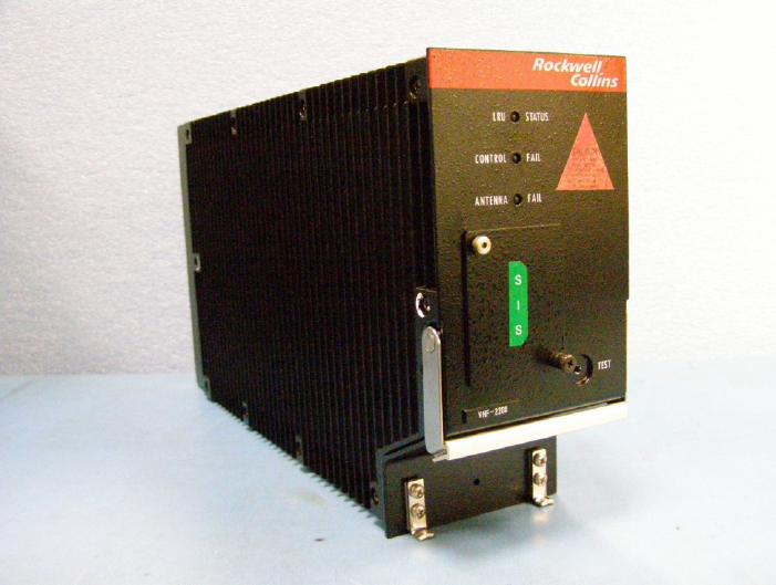
A complete self-test capability checks critical components in all receivers and
transmitters for proper operation. The ARINC 429 serial tune bus is also tested to
ensure that the unit is receiving valid tuning information from the frequency selector
system. LED indicators are provided to verify LRU, external frequency control and
antenna/transmission line integrity.
Mechanical Description
The VHF-2200 VHF Communications Transceiver is housed in a 3 MCU case designed
to mount in a rack that conforms to the provisions of ARINC specification 600. The VHF-
2200 is structured with formed aluminum members that include a front panel, a rear
panel, a bottom panel, a top panel, a central partition that rigidly maintains the alignment
of the other panels, and swing-out side panels.
Design
The table below details the characteristics of the VHF-2200.
CHARACTERISTIC
SPECIFICATION
Weight
4.8 kg (10.6 lbs) max
Cooling
Blow-through cooling metered along the plenum with various sized
holes
Overall dimensions
Width: 94.9 mm (3.74 in), max
Height: 200.0 mm (7.87 in), max
Length: 380.26 mm (14.98 in), max
Test report reference
FAA TSO- C128a, C160, C169a
Design specification
ARINC 429P1-16, 429P2-15, 429P3-18, 600-9, 604-1, 615-3, 618-
8, 631-5, 714-3, 716-11, 724B, 748, 750-4, 758-2
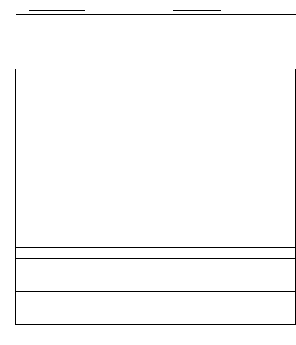
CHARACTERISTIC
SPECIFICATION
documents
RTCA DO-160E, DO-178B, DO-186B, DO-207, DO-224B, DO-254,
DO-281A
EUROCAE ED-12B, ED-14E, ED-23B, ED-67, ED-92
Receiver Characteristics
CHARACTERISTIC
SPECIFICATION
Receiver
25-kHz Bandwidth
Sensitivity (voice and analog data)
2 µV hard (-107 dBm) for 6 dB (s+n)/n
Sensitivity (VDL Mode 2)
-98 dBm for .001 BER (.159 BFR)
Selectivity
6 dB maximum attenuation at ±8.0 kHz
60 dB minimum attenuation at ±17.0 kHz
8.33-kHz Bandwidth (voice only)
Sensitivity
2 µV hard (-107 dBm) for 6 dB (s+n)/n
Selectivity
6 dB maximum attenuation at ±2.8 kHz
60 dB minimum attenuation at ±7.3 kHz
Undesired Signal Frequency
Attenuated at least 60 dB (80 dB image)
Cross Modulation
Audio output at least 10 dB below that produced by
a 10-µV signal modulated 50% by 1000 Hz
Undesired Signal Frequency
Undesired level (50% modulation with signal
strength of 100 to 100 000 µV)
±25 kHz
10 000 µV
±50 kHz
20 000 µV
±100 kHz
60 000 µV
±500 kHz
100 000 µV
±1.0 MHz and greater
200 000 µV
Desired Signal
10-µV signal modulated 50% by 1000 Hz
Audio Power Output
40 mW maximum, adjustable to less than 5 mW
into a 600 ohm ±20% resistive load
(The nominal setting should be 10 mW at 1000Hz
with a RF input modulated at 85%)
Transmitter Characteristics
See table below

CHARACTERISTIC
SPECIFICATION
Transmitter
Output Power
25 watts minimum into a 50 ohm resistive load
(voice, analog data and Mode A); 15 watts
minimum into a 50 ohm resistive load (VDL
Mode 2)
Antenna Impedance
50 ohms
Frequency Stability
5 parts per million (±0.0005%)
Sidetone
40 mW maximum, adjustable to less than 5
mW into a 600 ohm ±20% resistive load
(The nominal setting should be 10 mW at
1000Hz with a RF input modulated at 85%)
Transmitter Spurious Emissions
Harmonic and other, less than -46 dBW
Modulation Level (voice and analog
data)
0.125 V rms input at 1000 Hz will modulate
the transmitter at least 90%; adjustable for
levels up to 20 dB higher
Speech Processing (voice and analog data)
Greater than 20 dB of compression (automatic
volume control)
Transceiver Operation
Transmit-to-Receive Time
50 ms, maximum (voice, analog data and
Mode A)
1.5 ms, maximum (Mode 2)
Receive-to-Transmit Time
50 ms, maximum (voice, analog data and
Mode A)
2.75 ms, maximum (Mode 2)
Frequency Range
118.000 to 136.992 MHz
Channel Spacing
25 kHz and 8.33 kHz
Tuning Input
Dual serial inputs, per ARINC 429
Data Inputs
Dual serial HS inputs, per ARINC 750
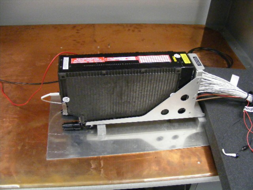
Installation:
The picture below details the VHF-2200 unit mounted in the ARINC 600 3MCU mount.
These type mounts have mechanical mechanisms to allow capture and restraint of the
front feet of the unit. This restraint ensures the unit will not come loose from the mount
and also that the ARINC defined connector does remains in contact with the rear pins.
The harness that connects the RMP to the VHF-2200 is defined by the aircraft
manufacturer. The pinout is defined by the ARINC 750 and 716 standard to allow
interchangeable product migration. The VHF-2200 pinout can be found below.
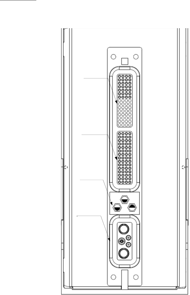
Rear Pin Out
Error! Reference source not found.The following pictures provide a generic depiction
of the VHF-2200 rear connector. The top, middle and bottom insert will be defined later
in this chapter.
Top Insert (TP)
Middle Insert (MP)
ARINC 600
Index Pin Code 04
Bottom Insert (BP)
VHF-2200 Rear Connector Layout (not to scale)

A
B
C
D
1
TEFO Enable
Input Discrete
COM B Mic.
PTT
Input Discrete
COM B Analog
Data Output - Hi
COM B Analog
Data Output - Lo
2
Reserved for
Monitor Port
Transmit
COM B
Voice/Data
Select
Input Discrete
Crosslink Output
- Hi
Crosslink Output
- Lo
3
Crosslink Input -
Hi
Crosslink Input -
Lo
DC Ground
Reserved for
Monitor Port
Receive
4
COM B ACR
Data
429 Output - Hi
COM B ACR
Data
429 Output - Lo
COM B ACR #1
Data
429 Input - Hi
COM B ACR #1
Data
429 Input - Lo
5
COM B Mic
Input - Hi
COM B Mic
Input - Lo
COM B
Audio/Sidetone
Output - Hi
COM B
Audio/Sidetone
Output - Lo
6
Shop Mode
Input Discrete
COM B Mic
Key Event
Output Discrete
COM B ACR #2
Data
429 Input - Hi
COM B ACR #2
Data
429 Input - Lo
7
COM B Mic
Input
Ground
Audio Ground
CMS Bus #2
429 Output - Hi
CMS Bus #2
429 Output – Lo
8
SPARE
SPARE
SPARE
SPARE
9
SPARE
SPARE
SPARE
SPARE
10
SPARE
SPARE
SPARE
SPARE
11
SPARE
SPARE
SPARE
SPARE
13
SPARE
SPARE
SPARE
SPARE
14
SPARE
SPARE
SPARE
SPARE
15
SPARE
SPARE
SPARE
SPARE
VHF-2200 Top Plug

A
B
C
D
1
COM A Mic
Input - Hi
COM A Mic
Input - Lo
COM A Mic.
PTT
Input Discrete
COM A Mic
Key Event
Output Discrete
2
Tx Timer Disable
Program Pin
COM A Mic
Input
Ground
Data Load
429 Input - Hi
Data Load
429 Input –Lo
3
NON-TEFO
Power Return
NON-TEFO
Power Return
Installation
Configuration
Program Pin #2
DC Ground
4
Self Test
Input Discrete
Audio Ground
Data Load
429 Output - Hi
Data Load
429 Output – Lo
5
Analog Data
Input - Hi
Analog Data
Input - Lo
Installation
Configuration
Program Pin #1
8.33 kHz
Program
Output Discrete
6
CMS #1
429 Input - Hi
CMS #1
429 Input - Lo
CMS #2
429 Input - Hi
CMS #2
429 Input - Lo
7
Tuning Port B
429 Input - Hi
Tuning Port B
429 Input - Lo
COM A
Voice/Data Select
Input Discrete
COM A Data
Key Line
Input Discrete
8
+28 VDC NON -
TEFO Power
Input
Data Load Enable
Input Discrete
+28 VDC NON -
TEFO Power
Input
Data Key Line
Return
9
SDI_1
Program Pin
SDI_0
Program Pin
SDI Common
Ground
COM B Muting
Output Discrete
10
Program Pin
Common
Spare
Input Discrete
COM A
ACR Data
429 Output - Hi
COM A
ACR Data
429 Output - Lo
11
Tuning Port A
429 Input - Hi
Tuning Port A
429 Input - Lo
Maintenance
System ID #2
Input Discrete
Freq/Func Data
Select
Input Discrete
12
COM A ACR #1
Data 429 Input -
Hi
COM A ACR #1
Data 429 Input -
Lo
COM A ACR #2
Data 429 Input -
Hi
COM A ACR #2
Data 429 Input -
Lo
13
COM A Analog
Data Output - Hi
COM A Analog
Data Output - Lo
Reserved for
Squelch Disable
Input Discrete
Reserved for
Squelch Disable
Return
14
Maintenance
System ID #1
Input Discrete
Air/Ground
Input Discrete
CMS Bus #1
429 Output - Hi
CMS Bus #1
429 Output - Lo
15
COM A
Audio/Sidetone
Output - Hi
COM A
Audio/Sidetone
Output - Lo
COM A Muting
Output Discrete
Muting Return
VHF-2200 Middle Plug
VHF-2200 Bottom Plug
BP1
ANTENNA COAX
COM A
BP2
+28 VDC
TEFO POWER
BP3
RESERVED
(RF CROSSLINK)
BP5
ANTENNA COAX
COM B
BP4
+28VDC TEFO
Power Return
(Isolated from Chassis)