Rofu Section 4A Wiring Diagrams Basic Diagram
User Manual: Rofu Rofu Basic Wiring Diagram Wiring Diagrams and Instructions
Open the PDF directly: View PDF ![]() .
.
Page Count: 8
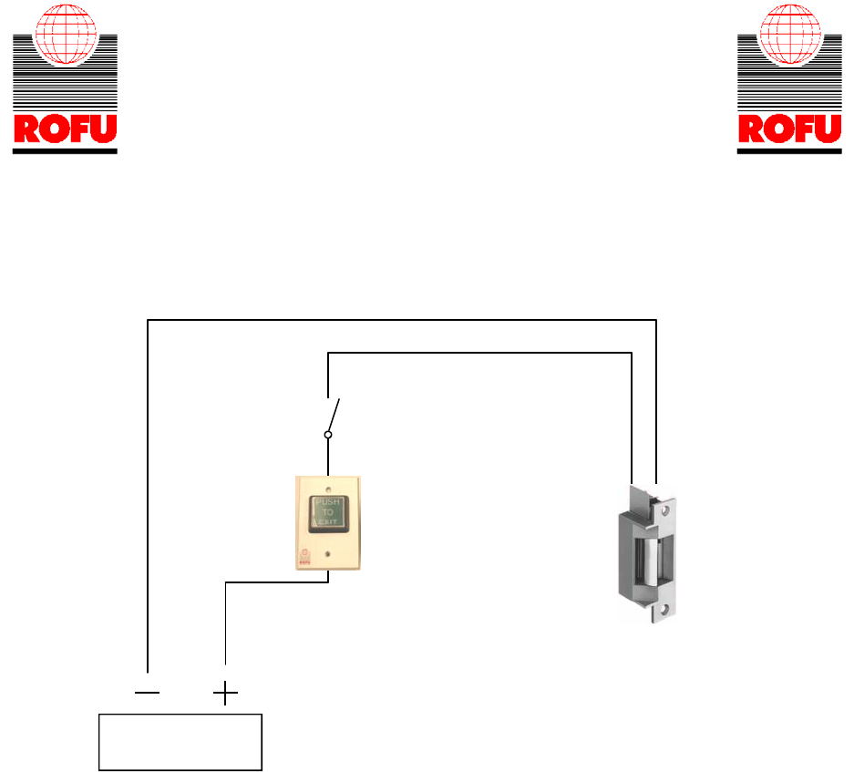
1
- WIRING INSTRUCTIONS—
fail secure strike with one button
Power Supply
Push Button
N/O
Fail Secure Strike
Polarity Insensitive
Depressing the push button would close the circuit, allow power to flow and release the strike.
Power Supply may be AC or DC, depending on the requirements of the strike.
In most cases AC power can be used intermittent (10 seconds or less). In most cases DC power can be used Continuous Duty (indefinite).
AC power will cause the strike to “buzz”, DC power will “click”.
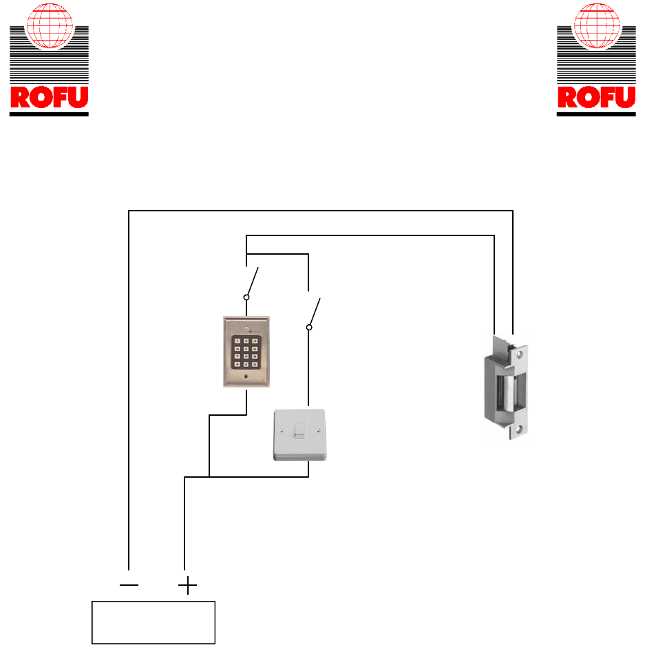
2
- WIRING INSTRUCTIONS—
fail secure strike with button and keypad
wired in parallel
Power Supply
Fail Secure Strike
Polarity Insensitive
Push Button
N/O
N/O
Depressing the push button or activating the keypad would close the circuit, allow power to flow and release the strike.
Power Supply may be AC or DC, depending on the requirements of the strike.
In most cases AC power can be used intermittent (10 seconds or less). In most cases DC power can be used Continuous Duty (indefinite).
AC power will cause the strike to “buzz”, DC power will “click”
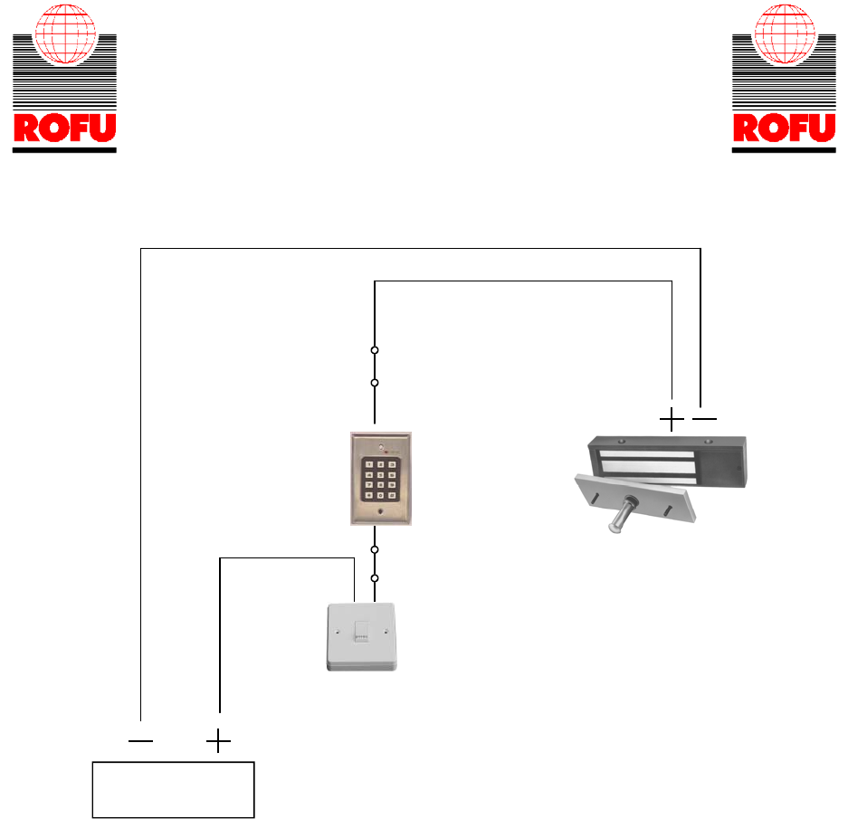
3
- WIRING INSTRUCTIONS—
fail safe strike with button and Keypad
wired in series
DC Power Supply
Electromagnetic Lock or a
Fail Safe Strike
(The strike is Polarity Insensitive)
Push Button
N/C
Depressing the push button or activating the keypad would open the circuit, stopping the flow of electricity and
causing the magnet or strike to release.
N/C
Power Supply for fail safe strikes and magnetic locks should be DC. If this is not available you may use an AC power source and wire inline a “Full
Wave Bridge” rectifier. This will convert the AC to DC. If you hear a “buzzing” sound, recheck your output on you power source to ensure that it is
DC output, or you can damage the magnetic lock or fail safe strike,
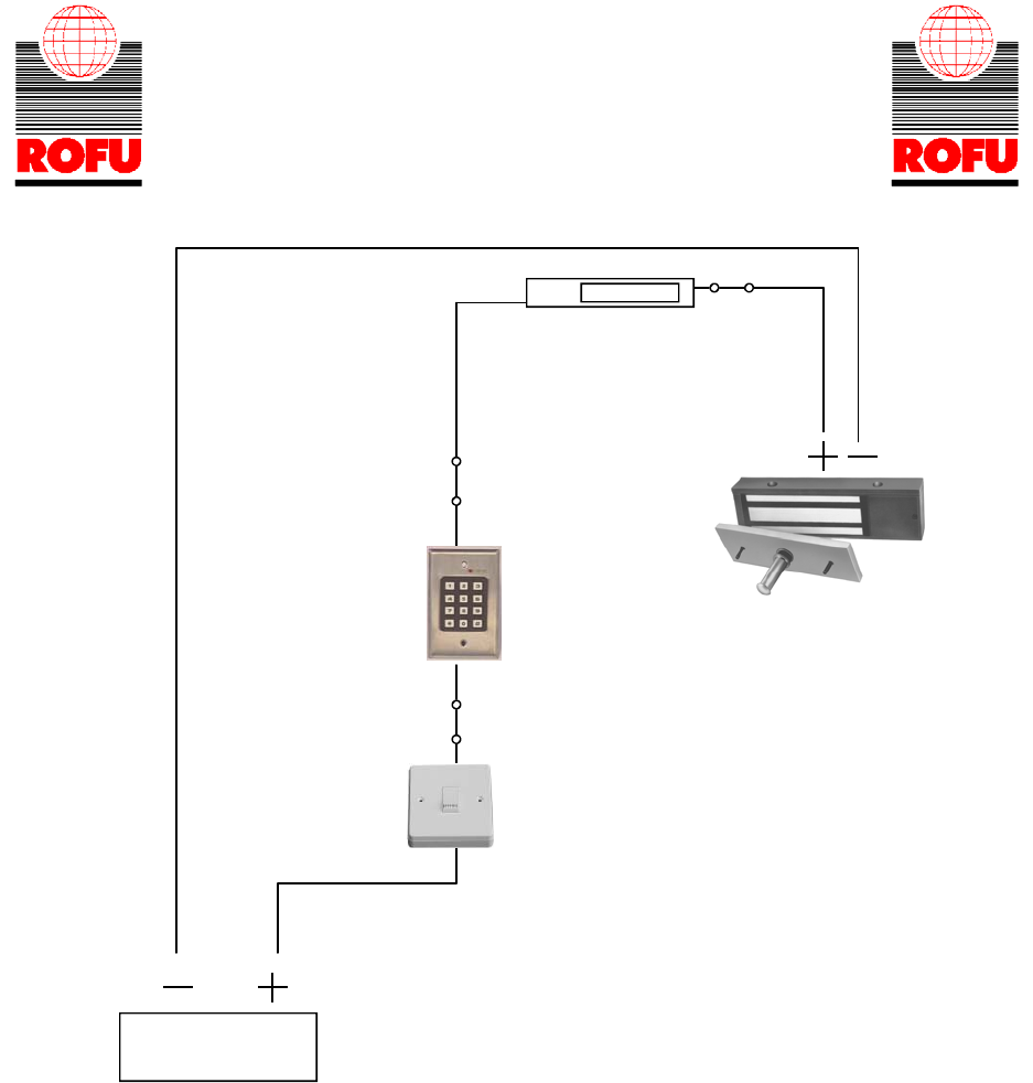
4
- WIRING INSTRUCTIONS—
magnetic lock or fail safe strike with button,
keypad and PIR
wired in series
Power Supply for fail safe strikes and magnetic locks should be DC. If this is not available you may use an AC power source
and wire inline a “Full Wave Bridge” rectifier. This will convert the AC to DC. If you hear a “buzzing” sound, recheck your output on you power
source to ensure that it is DC output, or you can damage the magnetic lock or fail safe strike,
DC Power Supply
Electromagnetic Lock or a
Fail Safe Strike
(The strike is Polarity Insensitive)
Push Button
N/C
Depressing the push button, activating the keypad or activating the PIR would open the circuit, stopping the flow of electricity
and causing the magnet or strike to release.
N/C
PIR N/C
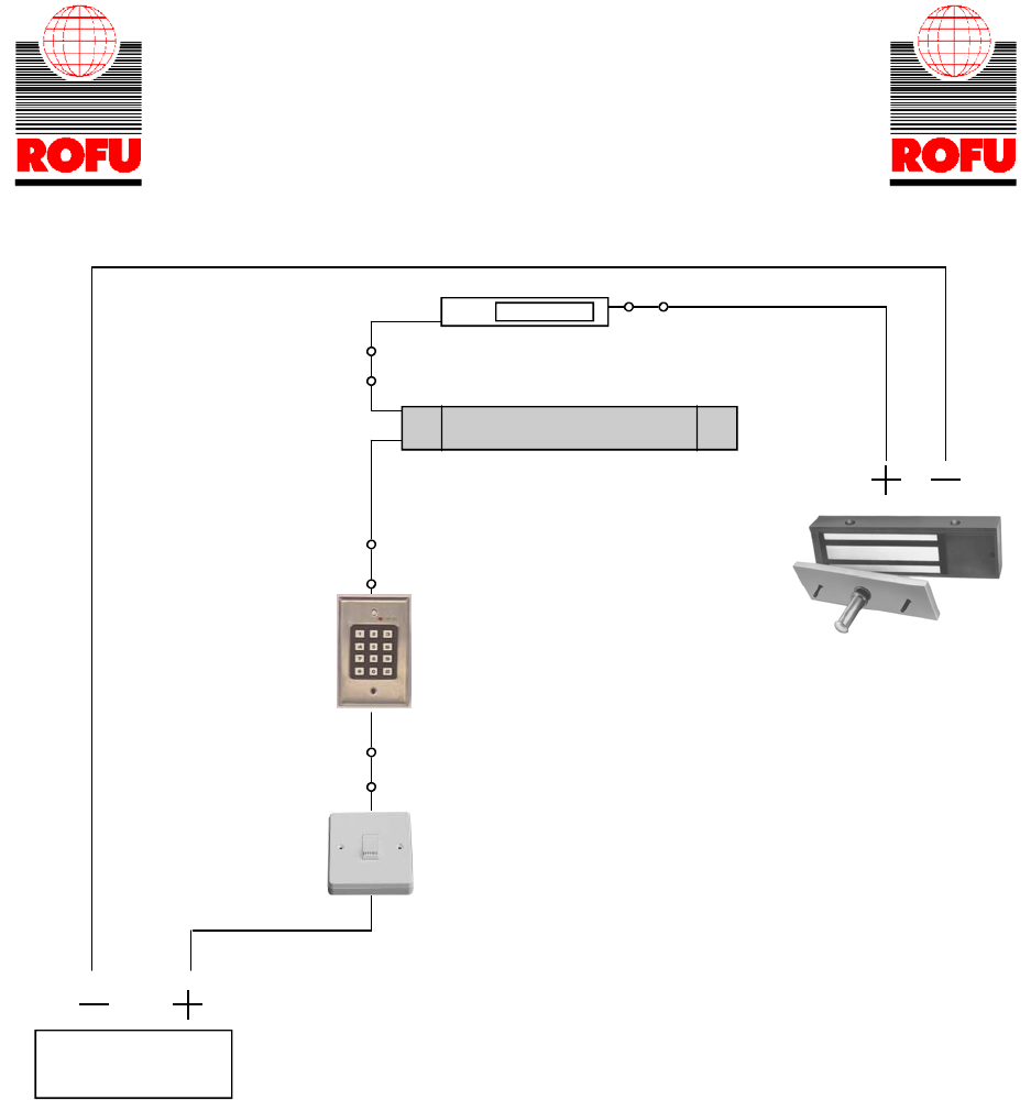
5
- WIRING INSTRUCTIONS—
magnetic lock or fail safe strike with button, keypad,
PIR and touch sense bar or micro-switch bar
wired in series
N/C
PIR
Power Supply for fail safe strikes and magnetic locks should be DC. If this is not available you may use an AC power source and wire inline a “Full
Wave Bridge” rectifier. This will convert the AC to DC. If you hear a “buzzing” sound, recheck your output on you power source to ensure that it is
DC output, or you can damage the magnetic lock or fail safe strike,
DC Power Supply
Electromagnetic Lock or a
Fail Safe Strike
(The strike is Polarity Insensitive)
Push Button
N/C
Depressing one of the push buttons, activating the keypad, activating the PIR or touching the bar would open the circuit,
stopping the flow of electricity and causing the magnet or strike to release.
N/C
N/C
Touch Sense bar or Micro-Switch bar
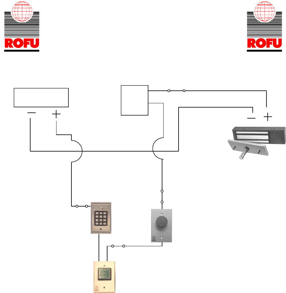
6
- WIRING INSTRUCTIONS—
Magnetic lock or fail safe strike with button, keypad,
maintained button and remote receiver.
wired in series
Power Supply for fail safe strikes and magnetic locks should be DC. If this is not available you may use an AC power source
and wire inline a “Full Wave Bridge” rectifier. This will convert the AC to DC. If you hear a “buzzing” sound, recheck your output on you power
source to ensure that it is DC output, or you can damage the magnetic lock or fail safe strike,
DC Power Supply
Electromagnetic Lock or a
Fail Safe Strike
(The strike is Polarity Insensitive)
Maintained
button
Depressing the push button, activating the keypad, activating the wireless button, or depressing the maintained button would open the circuit,
stopping the flow of electricity and causing the magnet or strike to release.
N/C
Receiver
N/C
N/C
Keypad
Push Button
7
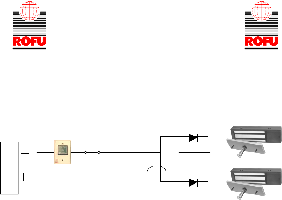
- WIRING INSTRUCTIONS—
Magnetic locks wired in parallel, with one button
controlling both magnets
We suggest using a IN4005 diode inline
magnets wired in parallel
Power Supply for fail safe strikes and magnetic locks should be DC. If this is not available you may use an AC power source and wire inline a “Full
Wave Bridge” rectifier. This will convert the AC to DC. If you hear a “buzzing” sound, recheck your output on you power source to ensure that it is
DC output, or you can damage the magnetic lock or fail safe strike,
IN4005 Diode
IN4005 Diode
DC Power Supply
N/C
Depressing the push button, would open the circuit, stopping the flow of electricity and causing both magnets or strikes to release.
Electromagnetic Locks or
Fail Safe Strikes
(The strike is Polarity Insensitive)
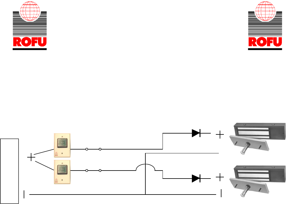
8
IN4005 Diode
IN4005 Diode
DC Power Supply
N/C
N/C
- WIRING INSTRUCTIONS—
Magnetic locks wired in parallel, with a
separate button controlling each magnet
We suggest using a IN4005 diode inline
magnets wired in parallel
Power Supply for fail safe strikes and magnetic locks should be DC. If this is not available you may use an AC power source
and wire inline a “Full Wave Bridge” rectifier. This will convert the AC to DC.
If you hear a “buzzing” sound, recheck your output on you power source to ensure that it is DC output,
or you can damage the magnetic lock or fail safe strike,
Depressing a push button, would open the circuit, stopping the flow of electricity to only one of the magnets or strikes to release.
Electromagnetic Locks or
Fail Safe Strikes
(The strike is Polarity Insensitive)
