User manual revised

Ver 0.3 ZyDAS WLAN Solution
ZyDAS WLAN Solution
ZDWlan_1211 User Guide
Version 0.3
ZyDAS
ZyDAS Technology Corporation
Doc. No.WLANUS1211 ZyDAS Confidential Information 1
2005/10/25
95.020T00
Ver 0.3 ZyDAS WLAN Solution
ZDWlan_1211 User Guide
1. How to Install ZD1211 driver and ZDWlan Utility:
1.1 Install: Phase 1
1.1.1 Copy the driver package (ex: 1211USB_Install_4214.exe) to any directory
of NoteBooK (or PC). The 1211USB_Install_4214.exe can be used at
ZD1211 Chip Set Only. It can be run on the Win98, WinME, Win2000 or
WinXP OS.
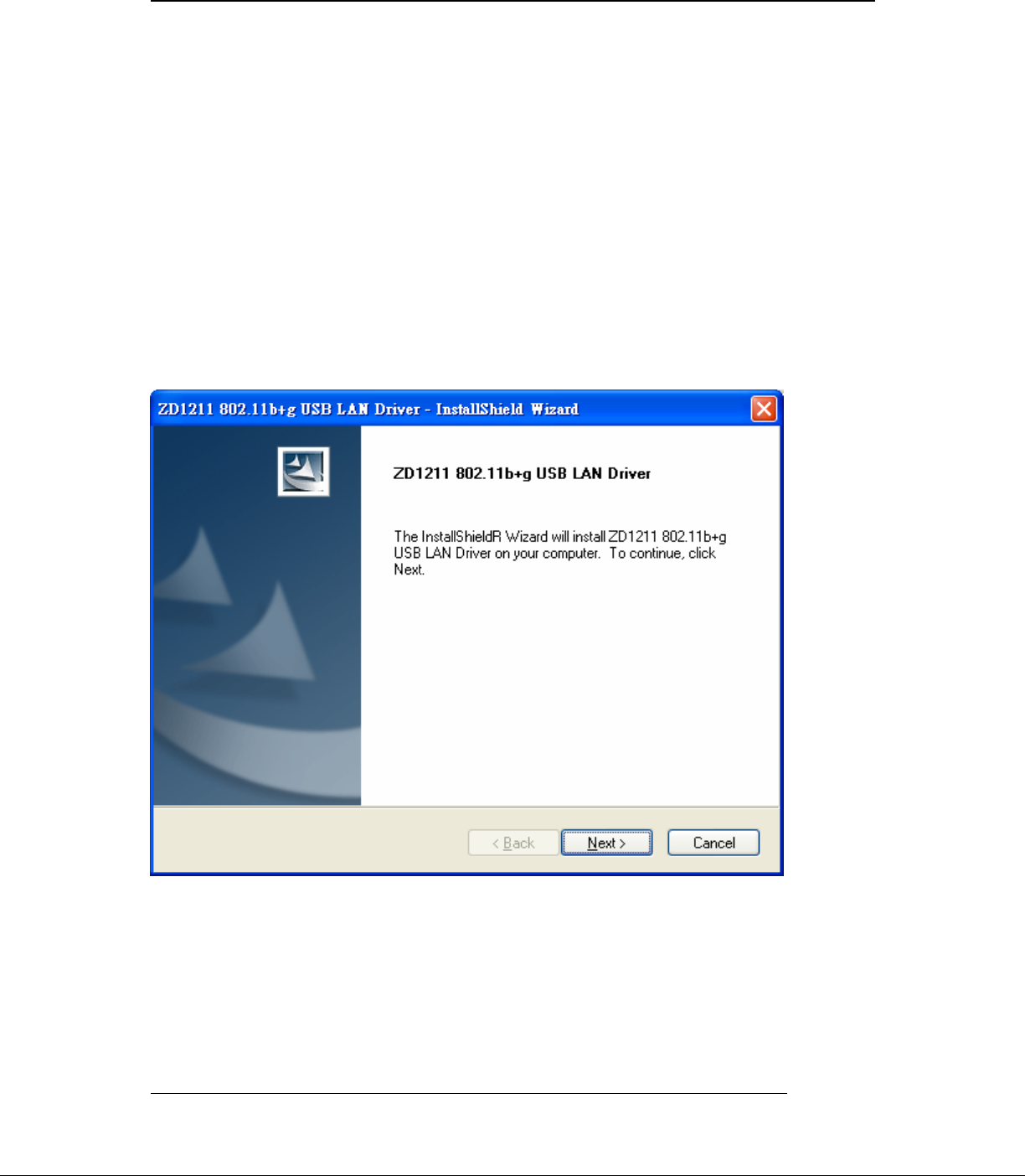
Figure 1-1
Doc. No.WLANUS1211 ZyDAS Confidential Information 2
2005/10/25
1.1.2 Click the package “1211USB_Install_4116.exe” then appear the
installation page shown as “Figure 1-1”.
95.020T00
Ver 0.3 ZyDAS WLAN Solution
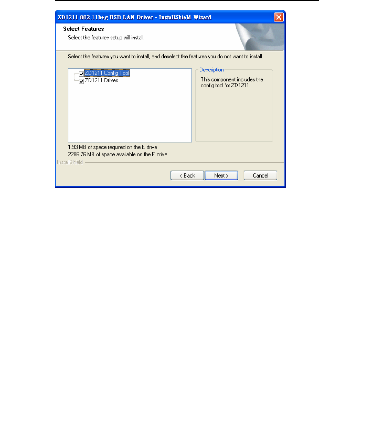
Figure 1-2
Doc. No.WLANUS1211 ZyDAS Confidential Information 3
2005/10/25
1.1.3 Press the “next” icon of Figure 1-1, then the page shown as “Figure 1-2”.
Select “ZD1211 Config Tool” or “ZD1211 Diver” or all of them to install
by checking the items.
Ver 0.3 ZyDAS WLAN Solution
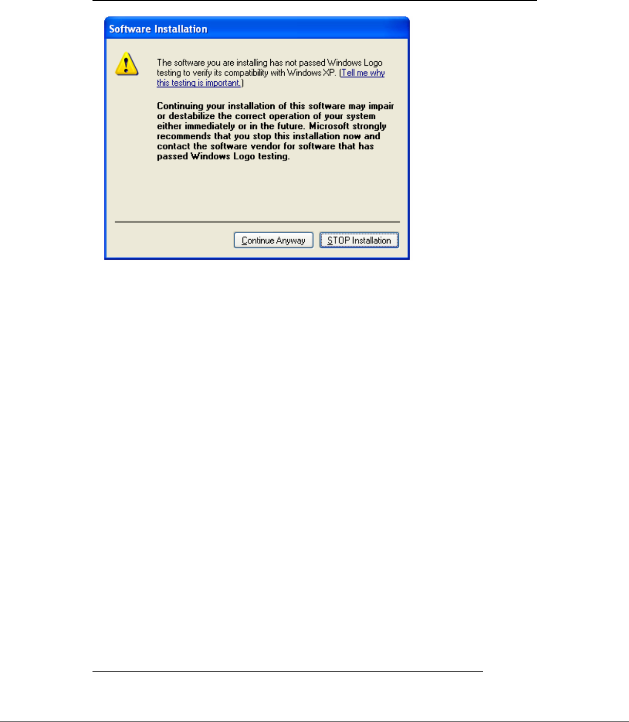
Figure 1-3
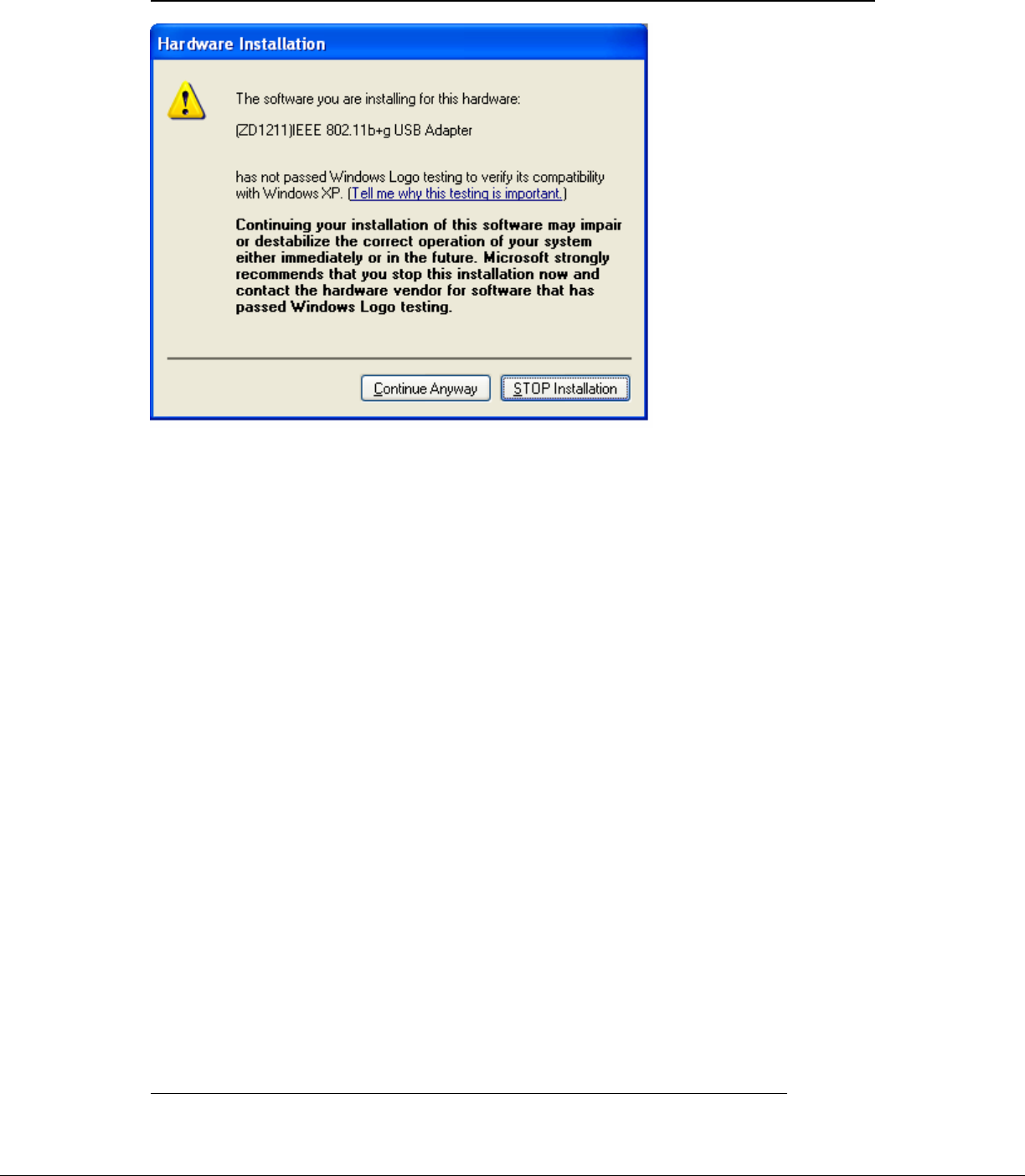
1.1.4 Press the “next ” icon of Figure 1-2, then the page shown as “Figure 1-3”.
Press the “Continue Anyway ” button of Figure 1-3, to finish the first
phase installation.
Doc. No.WLANUS1211 ZyDAS Confidential Information 4
2005/10/25
1.1.5 After finishing the phase 1 installation of the driver, the NoteBooK (or PC)
with Win98 or WinME OS shall be restarted, but Win2000 or WinXP OS
doesn’t need to be restarted.
Ver 0.3 ZyDAS WLAN Solution
1.2 Install: Phase 2
Figure 1-4
1.2.1 Insert the Wireless Card to slot of NB, then appear the installation page
shown as “Figure 1-4”.
For installing the driver automatically, please check the automation item.
Doc. No.WLANUS1211 ZyDAS Confidential Information 5
2005/10/25
Ver 0.3 ZyDAS WLAN Solution
Figure 1-5
Doc. No.WLANUS1211 ZyDAS Confidential Information 6
2005/10/25
1.2.2 When the automation item of “Figure 1-4” is selected, press “Next” button of
the page, then the “Hardware Installation” page shown as “Figure 1-5”.
Ver 0.3 ZyDAS WLAN Solution
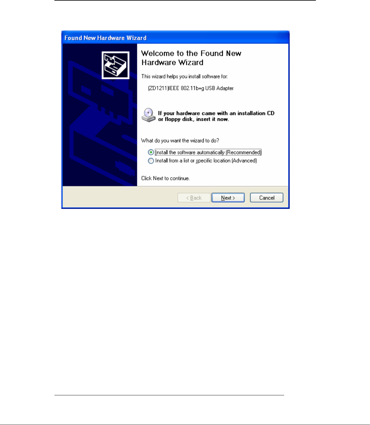
Figure 1-6
Doc. No.WLANUS1211 ZyDAS Confidential Information 7
2005/10/25
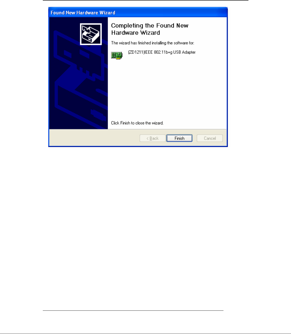
1.2.3 Press the “Continue Anyway ” button of Figure 1-5, then the page “Found
New Hardware Wizard” shown as “Figure 1-6”.
- Press the “Finish” button of “Figure 1-6” to finish the package
installation.
Ver 0.3 ZyDAS WLAN Solution
2. How to use the ZDWlan Utility: ( Station)
2.1 If you use the WinXP OS , the “Zero Configuration” of WinXP will be disable
first , then ZDWlan Utility can be used.
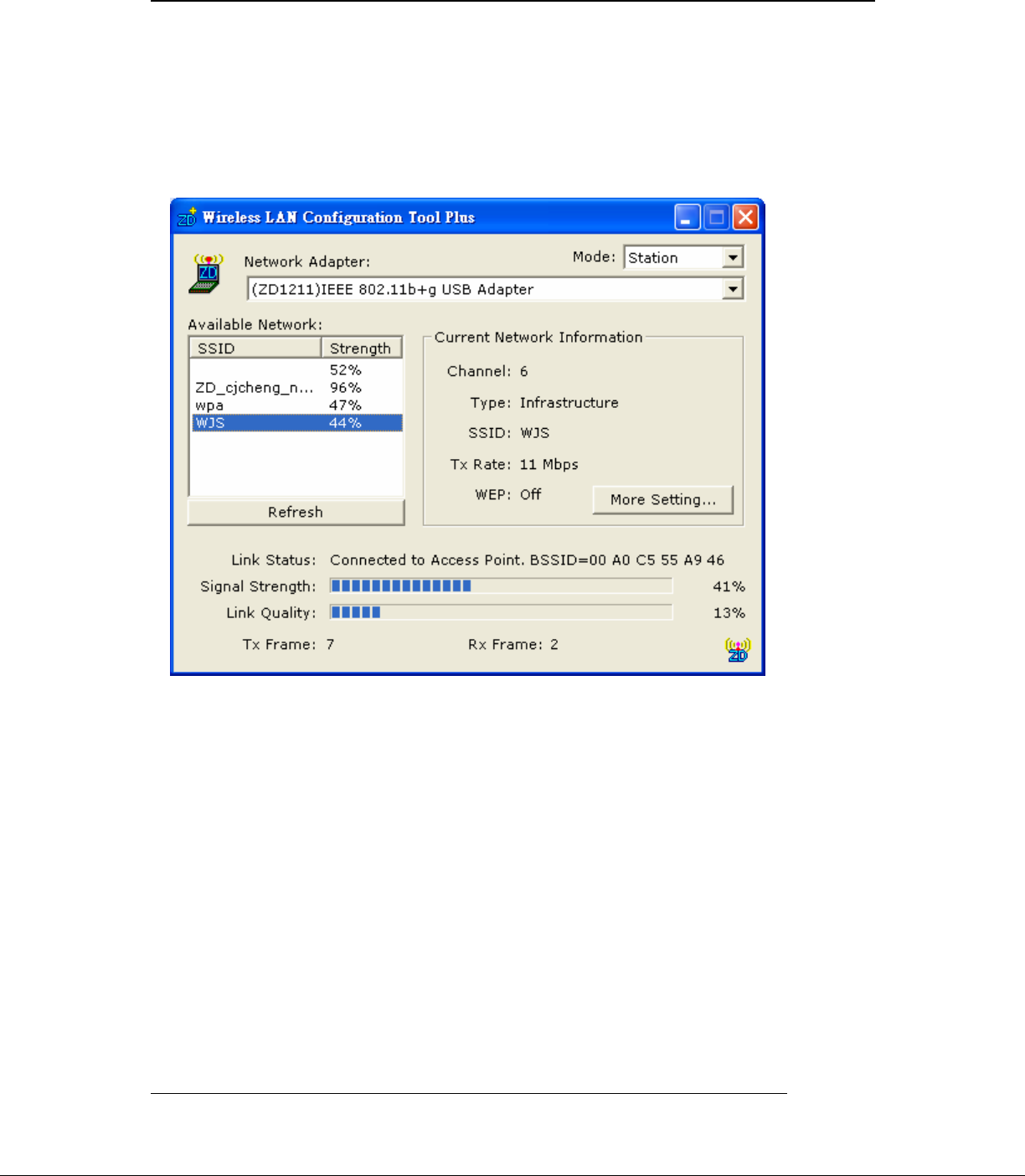
Figure 2-1
2.2 Open the ZDWlan Utility from “ Start menu bar \Program List \ ZyDAS 1211
Tool “. The Window is shown as “Figure 2-1”.
The adapter can be set at “Station” or “Access Point” Mode from the Mode drop
down menu. Station mode is selected for the item.
- You can site survey the neighboring SSID site by pressing the “Refresh”,
then sites name and signals strength of available SSID sites are shown on the
“Available Network” field.
- Double click the SSID site from “Available Network” field, and the SSID
can be connected directly.
Doc. No.WLANUS1211 ZyDAS Confidential Information 8
2005/10/25
- The information of the SSID is shown on the “ Current Network

Ver 0.3 ZyDAS WLAN Solution
Information”.
- Show the BSSID of connecting AP on the “Link Status” filed.
- “Signal Strength” and “Link Quality” shown on diagrammatic curve, and
described with percentage.
- Record the number of Tx frames on the filed of “Tx Frame”.
Doc. No.WLANUS1211 ZyDAS Confidential Information 9
2005/10/25
- Record the number of Rx frames on the filed of “Rx Frame”.
Ver 0.3 ZyDAS WLAN Solution
.
Figure 2-2
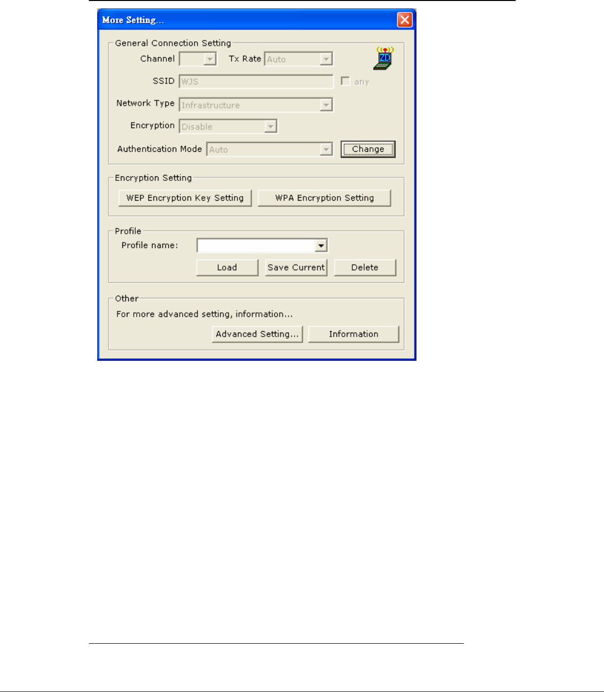
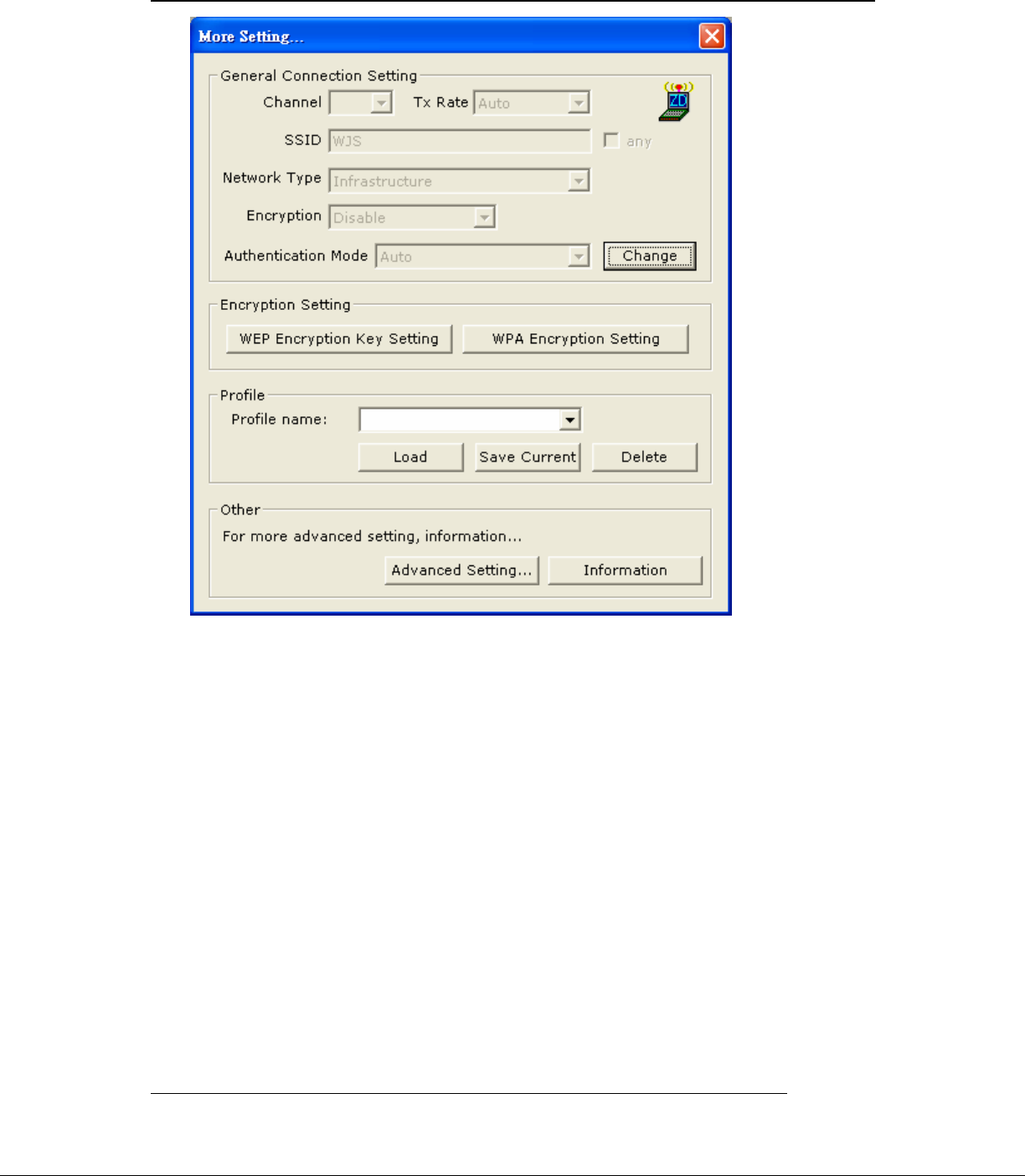
2.3 Click “ More Setting “ icon of Figure 2-1 to enter “More setting “ window. The
window is shown as “ Figure 2-2 ”.
Doc. No.WLANUS1211 ZyDAS Confidential Information 10
2005/10/25
2.3.1 “General Connection Setting” group:
- Read the current status from the group if the “Change” button is not
pressed.
- Press “Change” button for modifying the status, when the modification
is finished, press “Apply” to save it. The button “Change” and
“Apply” is alternately shown on the same position.
- Modify the SSID name from the “SSID” field. When use the item, the
“any “will be unchecked previously.
- Change the channel by drop down menu “ Channel”. When use the item,
the Ad_Hoc Mode will be set previously. .
- Select the transmission rate by “ Tx Rate” drop down menu.
Ver 0.3 ZyDAS WLAN Solution
- Select the “Ad_Hoc” or “Infrastructure” Mode by the “Network Type”
drop down menu.
- Select the “Enable WEP” or “Disable WEP” by the “Encryption” drop
down menu.
- Select the “Open System” , “Shared Key” mode or “Auto” from the
“Authentication Mode” drop down menu.
Doc. No.WLANUS1211 ZyDAS Confidential Information 11
2005/10/25
Figure 2-3
Ver 0.3 ZyDAS WLAN Solution
Figure 2-4
2.3.2 Encryption Setting :
Doc. No.WLANUS1211 ZyDAS Confidential Information 12
2005/10/25
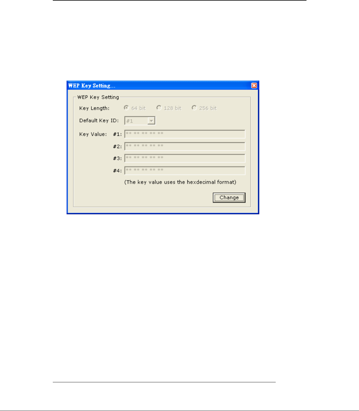
2.3.2.1 Press “WEP Encryption Setting” to enter the “WEP Key Setting” page
shown as Figure 2-3.
- Select the “Open System” , “Shared Key” mode or “Auto” from the
“authentication Mode” drop down menu.
- Press the “Change” button to modify the contents of “WEP Key setting”,
when it is finished, press “Apply” to save it. The button “Change” and
“Apply” is alternately shown on the same position.
- Select which key length 64,128 or 256 bits will be modified or used by
“Key Length” item.
- Select which key set will be use by the field of “Default Key ID”
Modify the 4 sets key depending on the selected key length on the field
of “Key Value”. The key value is used the hexadecimal format.

Ver 0.3 ZyDAS WLAN Solution
- Select which key format “hexadecimal” or “ASCII” will be used from
the “Key Format” .
2.3.2.2 Press “WPA Encryption Setting” to enter the “WPA Setting” page
shown as Figure 2-4.
- You can select the WPA authentication protocol “TLS” , “PEAP” or
“TTLS” from “Protocol” filed.
- “TLS” Setting: you don’t fill out the User name and Password field,
but the Certificate need to be used. When apply the setting, the “WPA
Setting page” must be closed.
- “PEAP” Setting: The User name, Password and Certificate are needed.
When apply the setting, the “WPA Setting page” must be closed.
-“ TTLS” Setting: The User name, Password and Certificate are needed,
and you must select the phase 2 authentication type (PAP, CHAP,
MSCHAP, MSCHAPv2) from the “ Phase2Auth” drop down menu.
When apply the setting, the “WPA Setting page” must be closed.
- If you select “pre-share-key” protocol , you can write down your
password on the filed of “Passphrase” , the password length can be
selected from 8 bytes to 63 bytes (ASCII format) depend on user .
When apply the setting, the “WPA Setting page” must be closed.
Doc. No.WLANUS1211 ZyDAS Confidential Information 13
2005/10/25
2.3.3 “Profile ” group:
- Select the profile that has been saved previously from the “Profile
name” drop down menu, then press “Load ” button to load the status to
use.
- Write the profile name on the field of “Profile name”, and press the
“Save Current” button to save the current status on the profile.
- Select the profile name that wanted to delete from the “Profile name”
drop down menu, and press “Delete” button to delete it
Ver 0.3 ZyDAS WLAN Solution
Doc. No.WLANUS1211 ZyDAS Confidential Information 14
2005/10/25
Figure 2-5
2.2.4 “Other” group:
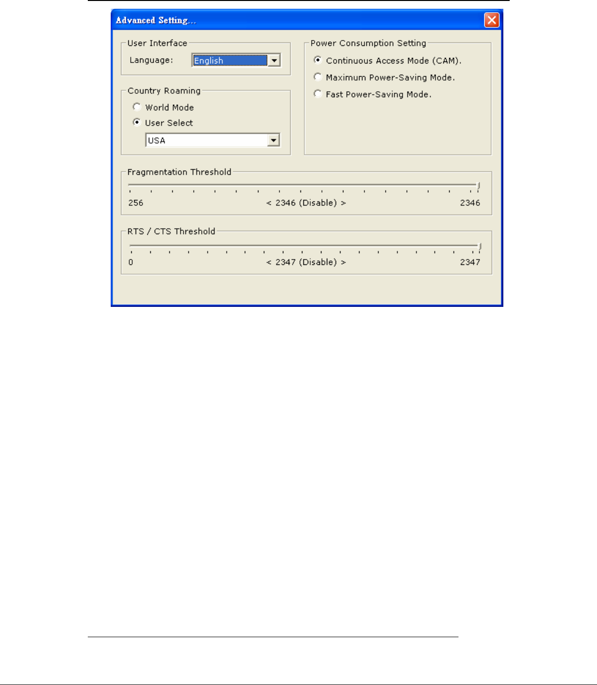
Press the “Advanced Setting” button, then the Advanced Setting page is
shown as Figure 2-5.
- Select the Window User Interface by the “Language” down drop menu.
If the English item is selected, all functions of window are described with
English. Select the Traditional Chinese item, and they are described with
Traditional Chinese.
- At “Power consumption Setting” group, select which power save level
want to be set by checking CAM Mode, Maximum Power-Saving mode or
Fast Power-Saving mode. The default is CAM mode. If the most save mode
want to use, select the Maximum Power-Saving mode, but it throughput is
lower than CAM and Fast Power-Saving mode. The throughput of “Fast
Power-Saving mode” is better than “Maximum Power-Saving mode”, but
its power save is less than “Maximum Power-Saving mode”.
- At “Country Roaming” group, the default depends on the region of
Ver 0.3 ZyDAS WLAN Solution
EEPROM. Select other region from “User Select” drop down menu, or
check “World Mode” item to set it to the word mode. When the word mode
is set, it depends on the behavior of AP. If the WLAN card is re-plug , the
setting will return to default setting.
- At “Fragmentation Threshold” bar, drop and move cursor to set the
fragmentation threshold point, the range is from 256 to 2346 bytes.
- At “RTS / CTS Threshold” bar, drop and move the cursor to set the RTS
threshold point, the range is from 0 to 2347 bytes.
Figure 2-6
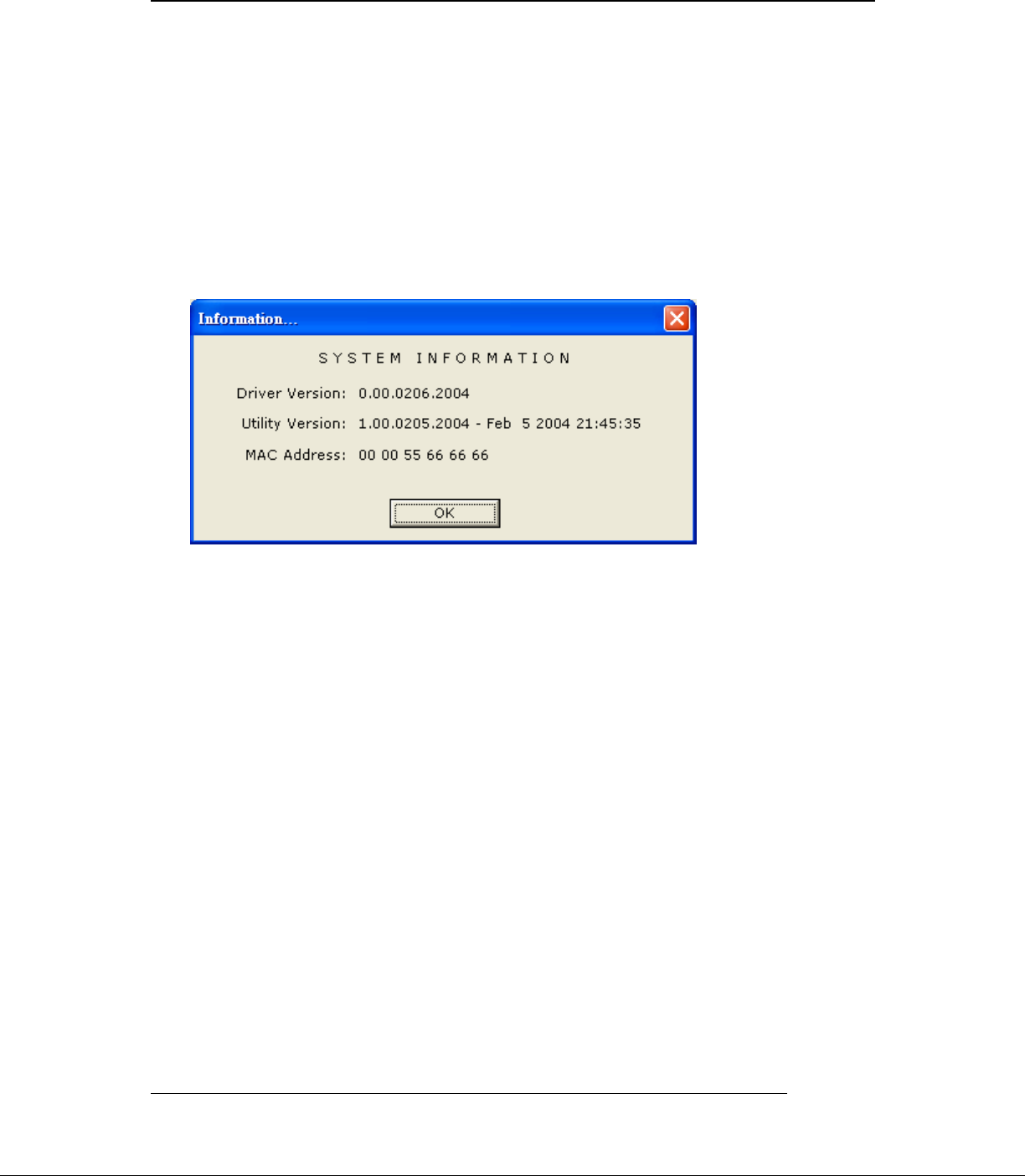
2.2.5 Press the “Information” button to enter the “Information” page shown as
Figure 2-6. It includes the Driver version, Utility Version and MAC
Address.
Doc. No.WLANUS1211 ZyDAS Confidential Information 15
2005/10/25
Ver 0.3 ZyDAS WLAN Solution
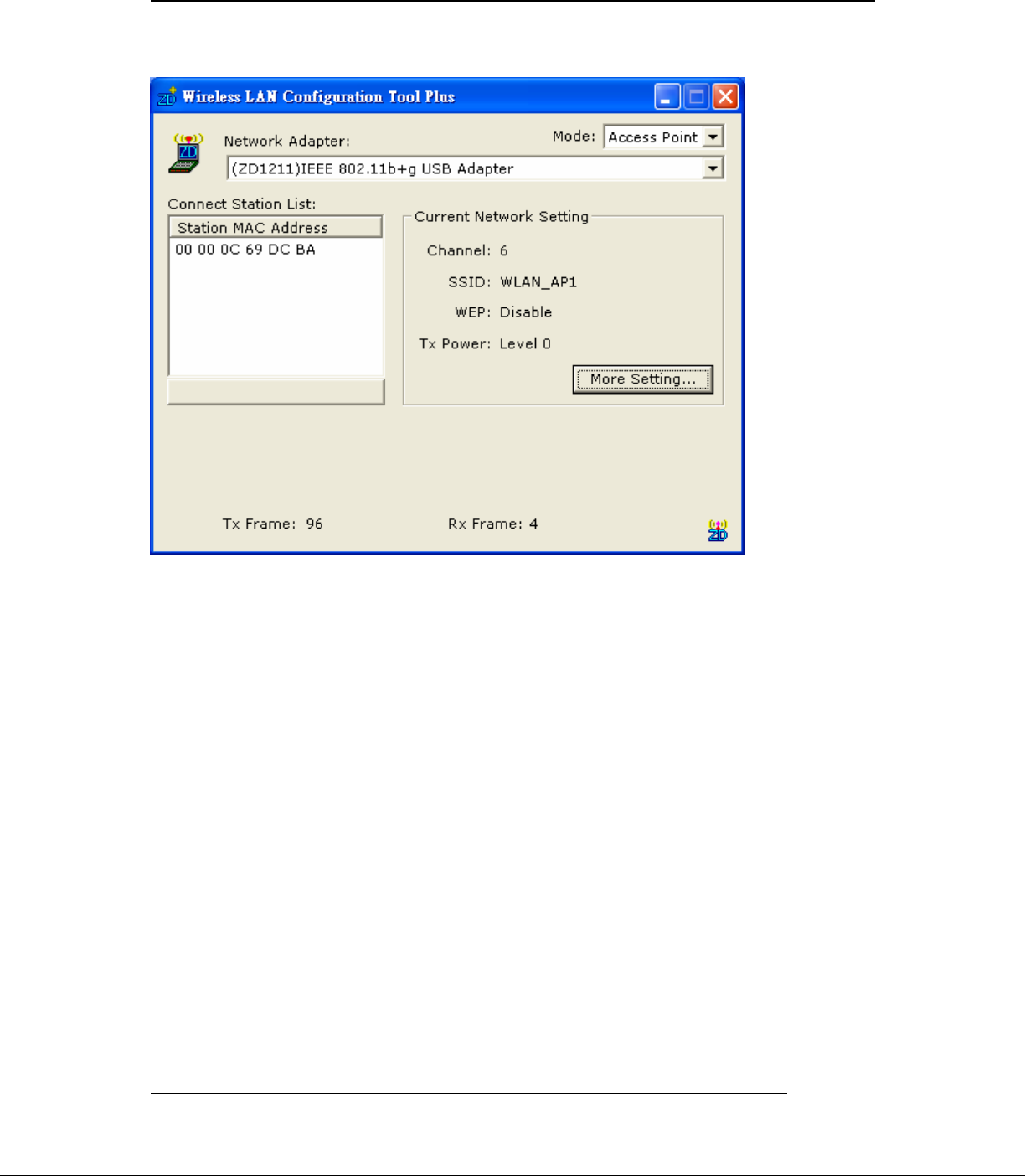
3. How to use the ZDWlan Utility: ( Soft Access Point)
Figure 3-1
3-1 Open the ZDWlan Utility from “ Start menu bar \Program List \ ZyDAS 1211
Tool “. The Window is shown as “Figure 2-1”. For the soft AP, please option the
“ Access Point” from drop down menu Mode filed, and it is shown as Figure 3-1.
- “Network Adapter” shows the available WLAN card for soft AP.
- If the WLAN stations link to the Soft AP , their MAC address will be
shown on the filed of the “Station MAC Address”.
- The current status of the AP is shown on the “current Network Setting”. It
can show which Channel is used, and what is the AP’s SSID. You can know
if the WEP is disable or enable. The Tx power level is shown on it too (The
is function not available now).
- The Tx Frame shows how many frames transmitted by the soft AP.
Doc. No.WLANUS1211 ZyDAS Confidential Information 16
2005/10/25
- The Rx Frame shows how many frames received by the soft AP.
Ver 0.3 ZyDAS WLAN Solution
Doc. No.WLANUS1211 ZyDAS Confidential Information 17
2005/10/25
Figure 3-2
Figure 3-3

Ver 0.3 ZyDAS WLAN Solution
Figure 3-4
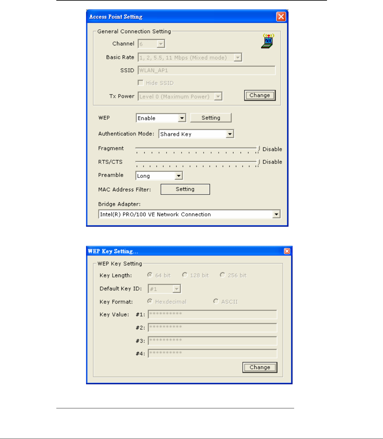
3-2 Click “ More Setting “ icon of Figure 3-1 to enter “More setting “ window. The
“Access Point Setting” page is shown as “ Figure 3-2 ”.
- Press the “Change” button to modify the “General Connecting Setting” ,
and press the “Apply” button , when the setting is finished. The button
“Change” and “Apply” is alternately shown on the same position.
- Select the channel from the drop down menu “ Channel”.
- The drop down menu "Basic Rate", ACK rate, can select four sets of basic
rates: set 1 {1, 2 Mbps (Mixed mode)}, set 2 {1, 2, 5.5, 11 Mbps (Mixed
mode)} , set 3 {1, 2, 5.5, 11, 6, 12, 24 Mbps (802.11g only)}, and set 4{6,
12, 24 Mbps(802.11g only)}. A 802.11b station can connect to the AP only
when the setting is set 1 or set 2. A 802.11g station is not limited.
- Modify the SSID name from the “SSID” filed.
- Check the “Hide SSID” to hide the SSID that means the WLAN station
can’t site survey the AP’s SSID.
- There are 4 sets transmit power level can be selected on the “Tx power”
filed.( The function is not available now.)
Doc. No.WLANUS1211 ZyDAS Confidential Information 18
2005/10/25
- Enable or Disable the WEP form the drop down menu “WEP”.

Ver 0.3 ZyDAS WLAN Solution
- Press the “Setting” button to open the “WEP key setting” shown as Figure
3-3. Press the “Change” button to modify the contents of “WEP Key
setting”, when it is finished, press “Apply” to save it. The button “Change”
and “Apply” is alternately shown on the same position. Select which key
length 64,128 or 256 bits will be modified or used by “Key Length” item.
Select which key set will be use by the field of “Default Key ID”. Modify
the 4 sets key depending on the selected key length on the field of “Key
Value”. The key value is used the hexadecimal format. Select which key
format “hexadecimal” or “ASCII” will be used from the “Key Format”.
- Select the “Open System” or “Shared Key” mode from the
“authentication Mode” drop down menu.
- At “Fragment” bar, drop and move cursor to set the fragmentation threshold
point, the range is from 256 to 2346 (Disable) bytes.
- At “RTS / CTS” bar, drop and move the cursor to set the RTS/CTS
threshold point, the range is from 0 to 2347(Disable) bytes.
- Select the Long preamble or Short preamble from the “Preamble” drop
down menu.
- Press the “Setting” button of “MAC Address Filter” to fill the MAC
addresses that will be accepted or filtered. It’s shown as Figure 3-4. Select
“Disable” or “Accept” or “Filter” from the filed of drop menu “Filter Type”.
There are 16 sets MAC addresses can be filled on the “Filter MAC
Address”. If all setting is finished, please press Apply to save it.
Doc. No.WLANUS1211 ZyDAS Confidential Information 19
2005/10/25
- Select the NIC card for bridge function from the filed of drop menu “Bridge
Adapter”. If the bridge function will be disable, please select the “ No
bridge” item from “Bridge Adapter”.
(Fig. 1) FCC ID: TC2N1000
FCC LABEL LOCATION
The label will be permanently affixed at a conspicuous location on the device.
Label
Federal Communication Commission Interference Statement
This equipment has been tested and found to comply with the limits for a Class B digital device, pursuant to
Part 15 of the FCC Rules. These limits are designed to provide reasonable protection against harmful
interference in a residential installation. This equipment generates, uses and can radiate radio frequency
energy and, if not installed and used in accordance with the instructions, may cause harmful interference to
radio communications. However, there is no guarantee that interference will not occur in a particular
installation. If this equipment does cause harmful interference to radio or television reception, which can be
determined by turning the equipment off and on, the user is encouraged to try to correct the interference by
one of the following measures:
- Reorient or relocate the receiving antenna.
- Increase the separation between the equipment and receiver.
- Connect the equipment into an outlet on a circuit different from that
to which the receiver is connected.
- Consult the dealer or an experienced radio/TV technician for help.
This device complies with Part 15 of the FCC Rules. Operation is subject to the following two conditions: (1)
This device may not cause harmful interference, and (2) this device must accept any interference received,
including interference that may cause undesired operation.
FCC Caution: Any changes or modifications not expressly approved by the party responsible for
compliance could void the user's authority to operate this equipment.
IMPORTANT NOTE:
FCC Radiation Exposure Statement:
This equipment complies with FCC radiation exposure limits set forth for an uncontrolled environment. This
equipment should be installed and operated with minimum distance 20cm between the radiator & your
body.
This transmitter must not be co-located or operating in conjunction with any other antenna or transmitter.
IEEE 802.11b or 802.11g operation of this product in the U.S.A. is firmware-limited to channels 1 through
11.
This device is intended only for OEM integrators under the following conditions:
1) The antenna must be installed such that 20 cm is maintained between the antenna and users, and
2) The transmitter module may not be co-located with any other transmitter or antenna,
3) For all products market in US, OEM has to limit the operation channels in CH1 to CH11 for 2.4G band by
supplied firmware programming tool. OEM shall not supply any tool or info to the end-user regarding to
Regulatory Domain change.
As long as 3 conditions above are met, further transmitter test will not be required. However, the OEM
integrator is still responsible for testing their end-product for any additional compliance requirements
required with this module installed (for example, digital device emissions, PC peripheral requirements, etc.).
IMPORTANT NOTE: In the event that these conditions can not be met (for example certain laptop
configurations or co-location with another transmitter), then the FCC authorization is no longer considered
valid and the FCC ID can not be used on the final product. In these circumstances, the OEM integrator will
be responsible for re-evaluating the end product (including the transmitter) and obtaining a separate FCC
authorization.
End Product Labeling
This transmitter module is authorized only for use in device where the antenna may be installed such that
20 cm may be maintained between the antenna and users. The final end product must be labeled in a
visible area with the following: “Contains FCC ID:TC2N1000”.
Manual InformationTo the End User
The OEM integrator has to be aware not to provide information to the end user regarding how to install or
remove this RF module in the user's manual of the end product which integrates this module.
The end user manual shall include all required regulatory information/warning as show in this manual.