Rolls Royce 1004227 Users Manual Design Evolution, Reliability And Durability Of Aero Derivative Combustion Turbines
1004227 to the manual 324bea1c-c516-4cd3-8775-dffb35cc17f3
2015-02-06
: Rolls-Royce Rolls-Royce-1004227-Users-Manual-524888 rolls-royce-1004227-users-manual-524888 rolls-royce pdf
Open the PDF directly: View PDF ![]() .
.
Page Count: 82

Design Evolution, Reliability and Durability of
Rolls-Royce Aero-Derivative Combustion Turbines
Pedigree Matrices, Volume 6
1004227
Effective December 6, 2006, this report has been made publicly available in accordance with Section 734.3(b)
(3) and published in accordance with Section 734.7 of the U.S. Export Administration Regulations. As a result
of this publication, this report is subject to only copyright protection and does not require any license agreement
from EPRI. This notice supersedes the export control restrictions and any proprietary licensed material notices
embedded in the document prior to publication.
EPRI Project Manager
D. Grace
ELECTRIC POWER RESEARCH INSTITUTE
3420 Hillview Avenue, Palo Alto, California 94304-1395 ▪ PO Box 10412, Palo Alto, California 94303-0813 ▪ USA
800.313.3774 ▪ 650.855.2121 ▪ askepri@epri.com ▪ www.epri.com
Design Evolution, Reliability and
Durability of Rolls-Royce
Aero-Derivative Combustion
Turbines
Pedigree Matrices, Volume 6
1004227
Technical Update, March 2006

DISCLAIMER OF WARRANTIES AND LIMITATION OF LIABILITIES
THIS DOCUMENT WAS PREPARED BY THE ORGANIZATION(S) NAMED BELOW AS AN
ACCOUNT OF WORK SPONSORED OR COSPONSORED BY THE ELECTRIC POWER RESEARCH
INSTITUTE, INC. (EPRI). NEITHER EPRI, ANY MEMBER OF EPRI, ANY COSPONSOR, THE
ORGANIZATION(S) BELOW, NOR ANY PERSON ACTING ON BEHALF OF ANY OF THEM:
(A) MAKES ANY WARRANTY OR REPRESENTATION WHATSOEVER, EXPRESS OR IMPLIED, (I)
WITH RESPECT TO THE USE OF ANY INFORMATION, APPARATUS, METHOD, PROCESS, OR
SIMILAR ITEM DISCLOSED IN THIS DOCUMENT, INCLUDING MERCHANTABILITY AND FITNESS
FOR A PARTICULAR PURPOSE, OR (II) THAT SUCH USE DOES NOT INFRINGE ON OR
INTERFERE WITH PRIVATELY OWNED RIGHTS, INCLUDING ANY PARTY'S INTELLECTUAL
PROPERTY, OR (III) THAT THIS DOCUMENT IS SUITABLE TO ANY PARTICULAR USER'S
CIRCUMSTANCE; OR
(B) ASSUMES RESPONSIBILITY FOR ANY DAMAGES OR OTHER LIABILITY WHATSOEVER
(INCLUDING ANY CONSEQUENTIAL DAMAGES, EVEN IF EPRI OR ANY EPRI REPRESENTATIVE
HAS BEEN ADVISED OF THE POSSIBILITY OF SUCH DAMAGES) RESULTING FROM YOUR
SELECTION OR USE OF THIS DOCUMENT OR ANY INFORMATION, APPARATUS, METHOD,
PROCESS, OR SIMILAR ITEM DISCLOSED IN THIS DOCUMENT.
ORGANIZATION(S) THAT PREPARED THIS DOCUMENT
EPRI
NOTICE: THIS REPORT CONTAINS PROPRIETARY INFORMATION THAT IS THE INTELLECTUAL PROPERTY
OF EPRI, ACCORDINGLY, IT IS AVAILABLE ONLY UNDER LICENSE FROM EPRI AND MAY NOT BE
REPRODUCED OR DISCLOSED, WHOLLY OR IN PART, BY ANY LICENSEE TO ANY OTHER PERSON
OR ORGANIZATION.
This is an EPRI Technical Update report. A Technical Update report is intended as an informal report of
continuing research, a meeting, or a topical study. It is not a final EPRI technical report.
NOTE
For further information about EPRI, call the EPRI Customer Assistance Center at 800.313.3774 or
e-mail askepri@epri.com.
Electric Power Research Institute and EPRI are registered service marks of the Electric Power
Research Institute, Inc.
Copyright © 2006 Electric Power Research Institute, Inc. All rights reserved.

iii
CITATIONS
This report was prepared by
Electric Power Research Institute
3420 Hillview Avenue
Palo Alto, CA 94304
Principal Investigator
D. Grace
This report describes research sponsored by the Electric Power Research Institute (EPRI).
The report is a corporate document that should be cited in the literature in the following manner:
Design Evolution, Reliability and Durability of Rolls-Royce Aero-Derivative Combustion
Turbines: Pedigree Matrices, Volume 6, EPRI, Palo Alto, CA: 2006. 1004227.

v
PRODUCT DESCRIPTION
Competitive pressures are driving power generators to exploit aviation combustion turbine
technology to create more efficient and powerful generation plants at lower cost. However, the
use of aero-derivative combustion turbines (third generation or "next generation") carry a degree
of technical risk because technologies incorporated into their design push them to the edge of the
envelope. This report reviews the design evolution and experience base of advanced Rolls-Royce
aero-derivative combustion turbines in a comprehensive format, which facilitates an assessment
of the technical risks involved in operating these high-technology combustion turbines. In
addition, a quantitative analysis-or reliability, availability, and maintainability (RAM)
assessment-is made for Rolls-Royce’s Avon, RB211 and Trent aeroderivative engines.
Results & Findings
Elements of aero-derivative technology developed in the 1970s form the basic design foundation
of the aero-derivative type machines of today. These designs have been refined over time to
provide proven, reliable, and maintainable designs while allowing the users the maximum degree
of flexibility in plant designs or configurations. The aero-derivative's greatest asset is its
modularity. With complete interchangeability of like modules and line-replaceable components,
it relies on a maintenance philosophy called "repair by replacement.” High performance, high
efficiency aero-derivatives are also fast starting and tolerant to cycling, characteristics that make
them suitable for peaking power and distributed generation applications. There are some generic
long-term problems associated with aero-derivatives, however, including bearings and seals that
require monitoring and conditioning equipment, Dry Low Emissions (DLE) combustion systems
that need refinement, and compressors sensitive to stall or surge.
The ultimate result of this report is a concise presentation of the design evolution of Rolls-Royce
combustion turbines in the form of a pedigree matrix that allows risk to be assessed. The
pedigree matrices identify design trends across all of a manufacturer's products that can be
categorized as low, medium, or high risk. Some of the trends identified as high risk include (1)
single crystal alloys and complex cooling schemes, (2) DLE combustion systems, and (3)
proprietary Thermal Barrier Coatings (TBCs) and bond coatings exclusive to industrial turbine
applications. Experience information includes site listings, O&M issues, and RAM-Durability
fleet data to provide a comprehensive assessment of model maturity.
Challenges & Objectives
Adapting aviation combustion turbine technology to power generation allows power companies
to benefit from development efforts and costs already absorbed by commercial and military
development programs. Computer-aided engineering and design programs and computer-aided
manufacturing programs make it possible to rapidly develop and produce new turbines.
However, this increased rate of change has increased the potential risk of new product

vi
introductions as design changes go from the ‘drawing boards’ into production testing at a
customer’s site early in the learning curve. The absence of long-term experience with the
technology raises issues of reliability and durability. For specific models and components,
chronic durability problems could result in insurability issues potentially undermining a project’s
financial structure.
Applications, Values & Use
This report, along with EPRI’s previously published design evaluations for GE aero-derivative
combustion turbines (EPRI report 1004220) and Pratt and Whitney aero-derivative combustion
turbines (EPRI report 1004222), provide a context for the risk assessment of currently available
aero-derived combustion turbine designs for power generation. This information is essential
background to generation planning and equipment procurement decisions. Aero-derivative
machines have been of particular interest due to their inherently short construction schedules,
fast startup times, and ease of maintenance, particularly in simple cycle configuration for
peaking and distributed generation service.
EPRI Perspective
To help project developers, owners and operators manage the risks of new combustion turbine
technologies, the durability surveillance report series supported by the EPRI New CT/Combined
Cycle Design and Risk Mitigation Program provides a structured context for understanding
design changes that drive these risks and related life cycle O&M costs. This information fully
complements a machine selection process heavily based on first cost, efficiency, and delivery
schedule. The multi-volume report series, along with regular updates, covers heavy-frame and
aero-derivative turbine product lines manufactured by ALSTOM, General Electric, Pratt &
Whitney, Rolls-Royce, Siemens Power Generation, and Mitsubishi Power Systems.
Approach
The project team reviewed the design characteristics of the Rolls-Royce aero-derivative
combustion turbine product lines (RB211, RB211 Uprate, and the Trent) to assess the technical
risk associated with these advanced technology combustion turbine designs. Information was
drawn from operations data and directly from the owners of machine fleet leaders operating in
peaking, cycling or baseload service. The resulting pedigree matrix supplemented with reported
experience consolidates information for each combustion turbine model into a format that allows
the reliability status of the machines to be reviewed and major design changes or areas of
potential risk to be evaluated. In addition, the team determined RAM statistics from the fleet of
engines reporting to the Operational Reliability Analysis Program (ORAP) database.
Keywords
Combustion Turbines
Aero-Derivative Gas Turbines
Reliability
Durability
Risk Assessment

vii
ACKNOWLEDGMENTS
Thanks to Ted Gaudette (formerly of Strategic Power Systems, Inc.) and to Ian Langham of Ian
Langham & Associates Inc. for preparing the original report in 2002. Thanks to Rolls-Royce for
welcoming EPRI attendance at the Turbine Operator’s Conference in Houston in 2005. Thanks
to Dale Paul and Bob Steele at Strategic Power Systems, Inc. for providing current reliability
statistics for the Rolls-Royce engines reporting to the ORAP database.

EPRI Proprietary Licensed Material
ix
CONTENTS
1 INTRODUCTION ....................................................................................................................1-1
Risk Trends ...........................................................................................................................1-3
Current Technology Trends Related to Industrial Combustion Turbines: Low Risk ........1-3
Applied Aero Technology Trends Directly Transferred to Industrial Combustion
Turbines: Low to Medium Risk ........................................................................................1-3
Advanced Aero Technology Trends Transferred to Industrial Combustion Turbines:
Medium to High Risk ........................................................................................................1-4
Independently Developed Technology Applied to Industrial Combustion Turbines:
Medium to High Risk ........................................................................................................1-5
Other Risk Factors............................................................................................................1-6
The Use of Advanced Technology for Peaking Duty.............................................................1-7
Insurers and Lenders Perspective.........................................................................................1-8
2 ROLLS-ROYCE AERO-DERIVATIVE COMBUSTION TURBINE BACKGROUND..............2-1
Summary...............................................................................................................................2-1
RB211 Background Information ............................................................................................2-1
RB211 Horsepower Ratings.............................................................................................2-3
RB 211 Maintenance Approach........................................................................................2-4
Turnaround Time and Costs ........................................................................................2-5
Parts Life Upgrades .....................................................................................................2-5
Trent Background Information...............................................................................................2-7
Trent Maintenance Approach ...........................................................................................2-9
Avon Background Information...............................................................................................2-9
Pedigree Matrix for the RB211 and Trent 60 Engines.........................................................2-10
3 RELIABILITY, AVAILABILITY AND MAINTAINABILITY......................................................3-1
Data Analysis: Rolls-Royce Aero-derivative Engines...........................................................3-1
RAM Statistics: Avon, RB211 and Trent - All Duties .......................................................3-2
Additional RB 211 Operating Statistics.............................................................................3-4

EPRI Proprietary Licensed Material
x
RAM Assessment..................................................................................................................3-4
Conclusion ............................................................................................................................3-4
4 BIBLIOGRAPHY ....................................................................................................................4-1
Literature Citations ................................................................................................................4-1
A KNOWN ISSUES .................................................................................................................. A-1
B RB 211 MAINTENANCE SCOPE ......................................................................................... B-1
RB 211 - 2,000 Hour Inspection........................................................................................... B-1
RB 211 - 8,000 Hour Inspection........................................................................................... B-1
RB 211 - Midlife Workscope................................................................................................. B-3
On Removal..................................................................................................................... B-3
Rebuild ............................................................................................................................ B-6
RB 211 - Overhaul Workscope............................................................................................. B-7
On Receipt of Engine ...................................................................................................... B-7
C RAM TERMS AND DEFINITIONS ........................................................................................ C-1
D INSTALLATION LISTS......................................................................................................... D-1


EPRI Proprietary Licensed Material
xiii
LIST OF TABLES
Table 2-1 Pedigree Matrix: Rolls-Royce RB211-6562, RB211-6761, Trent 60 (DLE and
WLE) Engine Design Characteristics ...............................................................................2-11
Table 3-1 RAM Statistics: Fleet Characteristics for Avon, RB211, and Trent............................3-2
Table 3-2 RAM Statistics for Roll-Royce Avon, RB211 and Trent Engines – All Duties............3-3
Table 3-3 Additional RB 211 Operating Statistics......................................................................3-4
Table A-1 Listing of Known Issues for Rolls-Royce Units......................................................... A-1
Table D-1 RB211 Sites ............................................................................................................. D-2
Table D-2 Trent Sites................................................................................................................ D-4
Table D-3 Avon Sites................................................................................................................ D-5

EPRI Proprietary Licensed Material
1-1
1
INTRODUCTION
The power generation market place and the combustion turbine market in particular are evolving
at an ever-increasing pace. Market forces are driving the introduction of new technologies and
advanced combustion turbines designs. The introduction of these technologies inherently
involves risk. The economic pressure of a market moving towards deregulation intensifies this
risk of new technologies. Whereas in the past new products were gradually introduced into the
market, the demands of competing in an open market have driven the pace of incorporating new
technologies to improve profitability on a $/kW basis. The intent of this report is to allow a
qualitative assessment of the risks involved in the use of these new technologies to be made.
In reviewing the available information on the designs of the heavy-duty combustion turbines,
several immediate observations can be drawn on the progression and evolution of the
combustion turbine over the last several decades. The economic pressures in the market place
have driven the pace of incorporation of military and commercial aviation combustion turbine
technology (e.g. single crystal turbine blades) into the power generation market. This increased
rate of design changes has also increased the potential risk of the new product introductions.
This increased risk is incurred for several reasons but is primarily attributed to going from the
‘drawing boards’ into production testing at a customer’s site early in the learning curve before
the design changes have been fully tested and proven over time.
In the past, the rate of incorporation of military and commercial aviation combustion turbine
technology into industrial combustion turbines was slow due to limited production schedules
(compared to military or commercial aviation) and largely limited to the under 50 MW class of
industrial aeroderivative combustion turbines. In recent years, this technology is being
incorporated into the new generation frame machines to create more efficient and powerful
plants at lower costs by:
• Taking advantage of the development efforts and costs initially absorbed by the commercial
and military development programs
• Availability of computer-aided engineering and design programs (CAE/CAD)
• Computer-aided manufacturing programs (CAM), and the current worldwide manufacturing
capability
The advanced frame machines being produced today and the future Advanced Turbine System
(ATS) machines sponsored by the U.S. Department of Energy are blending these technologies
more quickly and producing hybrid combustion turbines with frame technologies, aero designed
flow paths, aero designed cooling technologies, and industrial designed low NOx combustion
systems. The advanced industrial machines have even surpassed the military and commercial

EPRI Proprietary Licensed Material
Introduction
1-2
turbines in combustion technology with dry low NOx and CO levels that are several orders of
magnitude lower and meet land based pollution requirements in many geographic areas.
The enabling technology of today’s advanced frame machines lies with the computer codes and
manufacturing processes developed by the aviation combustion turbine industry. The application
of these processes is inevitable under the pressure of the power generation industry to produce
power at low cost with maximum efficiency, reliability, and availability.
The power generation combustion turbines have different operating demands than the aviation
combustion turbines and the designers and developers have programs in place to advance the
technology beyond the aviation programs. Manufacturers have extended the technology to more
advanced industrial thermal barrier coatings (TBCs), oxidation resistant coatings, bond coat
technologies, large size single crystal blade and vane manufacturing processes, single digit dry
low NOx combustion systems, and integrated electronic digital control systems handling more
than 4800 I/Os.
The trends by all the major manufacturers are similar with the adoption of the aviation
technology into the flow paths, with corresponding advances in materials, cooling schemes,
coatings, and clearance control. The basic approach, inherent in each manufacturer’s design
philosophy, is evident in their general combustion turbine designs (rotors, combustion systems,
and proprietary technology) but the general trend to higher firing temperatures, pressure ratios,
efficiency, low emissions, reliability (99%), and availability (96%) goals is similar. The overall
approach to compete worldwide is based on cost per MW. Supporting the supplied equipment
with long term maintenance contracts is the internal corporate incentive to provide reliable
equipment and designs. With the merging of companies and aviation and industrial technologies
to maintain competitiveness, the large frame combustion turbines are ‘hybrids’ absorbing
technology that previously lagged by a decade before incorporation into industrial turbines. The
industrial aero-derivative and some advanced frame combustion turbines are to the point of being
the leading edge of technology in the overall combustion turbine environment in terms of
efficiency, emissions, and advanced technology.
This strategy by the manufacturers is propelled in large part by advanced combustion turbines
becoming the “only game in town” due to the current worldwide disfavor with nuclear and fossil
boiler plants. The requirement to provide sited power quickly and cost effectively, with
guarantees, is pushing these technologies forward at a rapid pace.
In order to understand the risk associated with new product introductions, the changes in the new
products must first be understood. The design evolution of these machines have been reviewed
and incorporated in a Pedigree Matrix. The pedigree matrix consolidates information for
selected combustion turbine models into a format that allows the design evolution of the
advanced machines to be reviewed and major design changes or areas of potential risk to be
evaluated.

EPR Proprietary I Licensed Material
Introduction
1-3
Risk Trends
Based upon the review of the designs from all of the manufacturers, several trends are readily
apparent. These trends in the development of advanced designs involve incorporation of current
industrial combustion turbine technology, transfer of aircraft engine technology to industrial
combustion turbines, and new technologies developed specifically for industrial combustion
turbines. The subsections below discuss these trends in general terms and categorize the trends
in terms of relative risk (Low Medium, or High).
Current Technology Trends Related to Industrial Combustion Turbines: Low Risk
Elements of aero-derivative class technology developed in the 1970s form the basic design
foundation of the aero-derivative type machines of today. These designs have been refined over
time to provide proven, reliable, and maintainable designs while allowing the users the
maximum degree of flexibility in plant designs or configurations. These design trends, which
can be considered relatively low risk with respect to product reliability, include:
• High Degree of Modularity and Interchangeability
• Flight engine heritage provides for modular construction with separate sections completely
interchangeable with other like modules.
• Compact size allows for ease of maintenance and allows for easy removal in sections or in its
entirety with relatively common tools.
• Bolted on accessories and on-engine instrumentation that is accessible and designed for ease
of removal and replacement.
• High degree of commonality with the flight engine to retain durability gains of proven
hardware and retain lower costs due to higher production rates.
• Pre-tested packaged power units with small foot print for multiple units per site
• Fast starting and loading with tolerances to cycling duty.
• Easily adapted to cogeneration and combined cycle configurations.
Applied Aero Technology Trends Directly Transferred to Industrial Combustion
Turbines: Low to Medium Risk
Technology transfer with minimum risk to industrial aero-derivative and frame type combustion
turbines based on proven designs from the military/commercial combustion turbine have been
accomplished with CAE/CAD/CAM programs and analyses. The result is dramatic efficiency
and airflow performance improvements (e.g. air and gas flow paths) without impacting the
reliability or availability of the combustion turbine. Variable position compressor vanes have
contributed to improved part load performance and are desirable for DLE combustion.
Aerodynamic 2D and 3D designs have improved surge margins, compressor efficiency, and
general operability ranges. The aero-derivative compressors are sensitive to the occurrence of
surge and usually require a borescope inspection after a surge occurs to inspect for any

EPRI Proprietary Licensed Material
Introduction
1-4
abnormality in the flow path. Adoption of proven aviation technology has minimized leakage
paths and has improved clearance control. These aviation to industrial transfer technology
trends, which can be considered low to medium risk with respect to product reliability include:
• Advanced compressor designed flow paths
− Controlled diffusion airfoils
− Multiple circular arc airfoils
− Double circular arc airfoils
− 2D and 3D aerodynamics
− Variable vanes
− Shrouded stators with improved labyrinth seals
− Increased surge margins
− Exit (outlet) guide vanes
• Active and Passive Clearance and leakage control
Advanced Aero Technology Trends Transferred to Industrial Combustion
Turbines: Medium to High Risk
Hot end technology transferred to industrial turbines with firing temperatures in the
2300 o - 2600oF (1260o – 1427oC) range has been a challenge because of the duty cycle imposed
on the land-based turbine. The advanced materials (e.g. single crystal [SC] castings), exotic
cooling schemes, advanced coatings, and clearance control all had to be scaled to the sizes
utilized in the larger frame sized combustion turbine. Designing the 3D aerodynamic flow path
and providing adequate cooling for all the required blade and vane rows without exceeding base
metal temperature was required while maintaining durability, acceptable stress levels, and
vibratory characteristics.
The manufacturing of turbine blades and vanes with single crystal technology and the
development of appropriate coatings and bond coatings for these materials is a challenge for the
designers and manufacturers and currently should be classified as medium to high risk due to the
current level of experience in the field. These advanced aviation to industrial transfer technology
trends, which can be considered medium to high risk with respect to product reliability include:
• Turbine flow path
• 2D and 3D aerodynamics
• Advanced cooling technology*
− Convection cooling schemes
− Impingement cooling schemes
− Film cooling schemes

EPR Proprietary I Licensed Material
Introduction
1-5
− Multi-pass serpentine cooling schemes
− “Shower-head” cooling schemes
• Advanced materials
− Directionally solidified alloys
− Single crystal alloys*
− Low sulfur alloys*
• Advanced coatings
− TBCs*
− Oxidation coatings*
• Clearance and leakage control
− Passive
− Active*
− Abradable shrouds/labyrinth seals
− Brush seals
* Higher risk technologies
Independently Developed Technology Applied to Industrial Combustion Turbines:
Medium to High Risk
Some technological advances require independent design and development for the conditions
and environment the land based combustion turbines experience. The exhaust emission
requirement is a prime example where current regulations require NOx emissions below 25
ppmv, with an increasing number of locations requiring single digits. The aviation industry has
not yet addressed this challenge. The duty cycle of the aviation combustion turbine requires
take-off temperature for 150 to 300 hours total during its overhaul cycle (operational time to
depot repair) whereas the industrial land based turbine with DLE control, turndown
requirements, inlet heating, and ambient temperature could conceivably operate at continuous
rated power and rated firing temperature for the majority of its overhaul cycle. Since the time at
temperature constraint is greater for the industrial combustion turbine, the TBCs, oxidation
coatings, bond coatings, and materials must survive in a much harsher environment long-term
than the commercial aviation equivalent combustion turbine. Reliability and durability of this
technology is considered medium to high risk because much of the enabling technology has to be
developed and proven. Existing advanced systems are complex and have yet to be proven for
long term durability. Blades that have exotic coatings, in some cases, cannot be stripped and
recoated, thus are non-repairable and may not achieve full design life for the combustion turbine
design. This results in increased life cycle costs. Steam cooling for the combustion transition
pieces, vanes, and/or blades is being developed by manufacturer, university and DOE/ATS

EPRI Proprietary Licensed Material
Introduction
1-6
development programs and is entering commercial use. Advanced industrial technology trends
which are considered medium to high risk with respect to product reliability include:
• Dry low NOx Combustion systems*
• Cannular and annular designs with multiple fuel injection nozzles
• Exclusive industrial TBCs and bond coatings*
• Exclusive oxidation coatings*
• Closed loop steam cooling systems*
• External cooling air cooling systems
• Closed loop air cooling systems
• Staged combustion for high turndown capability
*Highest risk technologies
Rolls-Royce advanced aero technology is being applied to ALSTOM engines under a long-term
technology transfer agreement (ref. Diesel & Gas Turbine Worldwide April 2002, p. 4). Very
high temperature technologies, advanced aerodynamics, very high strength/high temperature
materials and protective coatings will be applied to improve efficiency, power output and
durability of ALSTOM’s heavy duty combustion turbines. Note that a technology transfer
agreement was in place with Westinghouse in the early 1990’s to apply advanced technology to
the frame 501F and G machines. Considering that Westinghouse and Mitsubishi Heavy
Industries developed the 501F/G machines jointly, the same technology may have been
incorporated into the 50 Hz 701F/G machines by MHI. Furthermore, Siemens subsequently
acquired Westinghouse, presumably gaining access to that previous technology as well.
Other Risk Factors
The transfer, development, and introduction of new hardware into the industrial power
generation environment are part of the scope of a system that contributes to the life cycle cost
picture. Hardware, first cost, and new advanced technology is misused if the integration of the
whole system from “cradle to grave” is not addressed, because hardware is only a portion of the
risk. Some elements of these “other risk elements” are summarized below. This is not intended
to be a complete list of items. These items may have as significant an impact on the successful
lifetime operation of the plant as the “advanced hardware” if not addressed adequately.
Users
• Experience/skill level
• Degree of training
• Cost reduction in O&M programs
• Heavy reliance on OEM’s

EPR Proprietary I Licensed Material
Introduction
1-7
• Single, large capacity units
• Minimum resources applied to Monitoring, Diagnostic, and Prognostic Programs
Original Equipment Manufacturers
• Integration of systems
• Competitive economics
• Corporate downsizing
• Sourcing compromises (country of sale or worldwide)
• Long term maintenance contracts (burden on OEMs) and extent shared with the suppliers
The Use of Advanced Technology for Peaking Duty
The attraction of the new technology combustion turbines, as compared to what can be called
“mature” technology combustion turbines, lies primarily in the increased thermal efficiency.
Current “Advanced Class” combustion turbines (those with firing temperatures of 2300oF
(1260oC) or greater) have simple cycle efficiencies that are approximately 2% better than their
“mature” technology or earlier counterparts. This efficiency increase makes an enormous
difference in operating costs over the life of the plant. Obviously, the more the plant operates,
the bigger the advantage would be.
The aero-derivative combustion turbines also offer more flexibility of power when multiple units
are at a single site. Fast starting and loading times means that multiple blocks of capacity can be
quickly dispatched in cycling duty with added flexibility for the User.
For many, new technology would be the clear choice, all other things being equal. However, all
other things are seldom equal. The other differences that must be evaluated are several. During
system peaks, when power can be sold at steep premiums, having the ability to produce some
fraction of plant total capacity (i.e. 4 of 6 RB211’s operating) can have a very favorable impact
on profitability versus one large frame unit down for an extended period of time.
New technology also pertains, separately, to environmental compliance and emissions
performance. Indeed, the mature classes of combustion turbines may be forced to utilize new
technology combustion systems to meet stricter emissions standards. Generally, higher NOx
emissions would be produced at the higher firing temperatures and the turbines with the highest
firing temperatures require the most sophisticated emission control technology. To control NOx,
and CO, manufacturers use complex combustion systems designed to precisely control the
fuel/air mixture and the combustion process in general. There is clear evidence that these
complex systems are not as robust as their simpler, low-tech counterparts. However, it is the site
emissions requirements that dictate the selection of combustion systems.
Consequently, the advantages of new technology combustion turbines must be evaluated against
the disadvantages. The cost of fuel will be a very important factor in the determination, as will
the expected service time of the unit. If service time is low, and the cost of fuel is low, then the

EPRI Proprietary Licensed Material
Introduction
1-8
efficiency advantage of the new technology combustion turbine might not offset the increased
maintenance costs. It is a difficult equation to solve, especially when trying to predict changes
over the 20 to 30 year life of a typical plant.
Insurers and Lenders Perspective
Technology risk is of interest not only to owners and operators but also to insurance companies
and project lenders. Insurers protect owners and lenders from major financial loss due to costly
but infrequent accidental events. In some cases, unproven technology and changes in design can
lead to catastrophic failures and/or extended durations of unavailability. Insurers are therefore
keenly aware of the introduction of new models and designs. Insurance for newly introduced
“prototype” designs typically require very high financial responsibility on the part of the
manufacturer until they have demonstrated several thousand hours of operation. At that point,
the new model enters the category of “unproven” until typically one to three units leading the
fleet have operated successfully for over 8,000 hours at rated conditions. During this period,
some components may be excluded from coverage, as well as design and manufacturing defects.
Depending on the results of this operating period, the insurer would then classify the model as
“proven”, although they may take exception to insurance coverage for certain high-risk
components until problems are resolved. In going from “prototype” to “unproven” to “proven”,
deductible and premium amounts are reduced as the insurer perceives less risk. Extensive testing
of the engines for reliability in a controlled environment such as a manufacturer facility is judged
as being far superior to field testing to demonstrate performance and reliability.
Advanced technologies are perceived as having more risk mainly because they are being used in
new applications and are being scaled up to larger capacities. Overall, insurers consider the
following factors as significantly extending the risk of accident:
• New designs (typically highlighted by a change in model name)
• Higher firing temperature
• Higher capacity/output
• Higher compressor pressure ratio
Major insurance companies closely monitor and track performance of the combustion turbine
suppliers and their specific models individually, and track their claim history for each model.
Some insurers retain more in-house engineering expertise than others, but all have become more
dependent upon OEM technical and marketing materials for information. Interestingly, some
combustion turbine models are rated differently by different insurers; manufacturers are
generally eager to get their models moved from “unproven” to “proven”, signaling more
acceptance by insurers and therefore easing the sale of their model to the project developer. It
appears that an insurer’s recent claim history and/or anecdotal evidence plays a major role in the
models risk rating.
Insurers expect to profit from their activities by the receipt of premiums and their investments.
However, their experience in the 1990’s was that insuring combustion turbines was a losing
business. In 2001 and 2002, premiums were increased and deductibles were increased to try to

EPR Proprietary I Licensed Material
Introduction
1-9
compensate for their losses. Some companies concluded they would no longer participate due to
the perceived risks, while others entered the market due to improving margins. In 2004 and
2005, the market again became “softer” and premiums decreased on a relative basis. The
insurance market appears to be fundamentally based on supply and demand of its “product”, with
volatility somewhat decoupled from quantified technical risk.
Project lenders are highly risk-averse to a multitude of risks, and require the project owner/
operator to carry insurance so that the cash flow to service the debt is secure. Typically, the
owner/operator obtains their insurance coverage through a broker, who deals with a number of
primary insurers to find the best financial arrangement for the insured. Although the primary
insurers actually underwrite the risk, issue the policies, and settle claims, they in turn pass along
much of their risk along to one of several reinsurance companies. In essence, the primary
insurers themselves are risk-averse and the primary insurance risks are aggregated by the re-
insurers.
The main type of insurance that is impacted by technical risk is Boiler and Machinery Insurance
(or Machinery Breakdown Insurance). This insurance covers direct damage from sudden and
accidental breakdown of mechanical, electrical or pressure vessel equipment, such as turbines,
boilers, generators, motors, pumps, transformers and switchgear. Deductible amounts are
typically set to be higher than the maximum loss that could be typically expected over the course
of the normal life, i.e. an amount that would be typically budgeted as an allowance for unplanned
maintenance, and that the project could sustain without jeopardizing its financial health.
Deductible amounts of $500,000 to $3,000,000, depending on project size, would not be
uncommon.
Business Interruption Insurance is sometimes also required, depending on the project. This
insurance covers the revenue lost due to the lack of generation i.e. unavailability, over an
extended period of time caused by an event covered under the Boiler and Machinery Insurance.
In this case, the deductible is typically expressed as a number of days, i.e. the maximum normal
number of days to obtain parts and install them if required to return the unit to service, typically
45-60 days, although longer periods result in lower premiums.
When insurers are quoting coverage level for a particular project and the annual premiums and
deductibles, many factors are considered. Besides the many aspects of uncertainty and costs
related to potential risks, insurers also consider the general marketplace for their products, the
degree of competition, and their ability to gain additional business associated with the power
project. Technology risk is one part of the equation
.

EPRI Proprietary Licensed Material
2-1
2
ROLLS-ROYCE AERO-DERIVATIVE COMBUSTION
TURBINE BACKGROUND
Summary
Rolls-Royce’s aero-derivative heritage goes back more that forty years with an active role in
establishing the combustion turbine in marine application with such units and the Proteus,
Gnome, Tyne Spey, and Olympus combustion turbine propulsion units. Rolls-Royce has more
than 975 marine installations with over 6 million operating hours. Many units are still operating
today.
The Proteus (2.7 MW/4,000 hp) and Avon (14MW/19,000 hp) combustion turbines were used in
industrial applications for electrical generation and mechanical drive applications since 1964.
These two units have more than 1200 units installed base with more 48 million operating hours.
The acquisition of Allison engines in 1994 added additional scope and experience in the 2-9 MW
range with various models of the Rolls Allison 501, 601, 570, and 571. The Rolls Allison family
of combustion turbines adds an additional 2200 units and 75 million operating hours of
experience.
Initial designs for the aero-derived industrial RB211 began in 1965 with the first installation in
1974 in pipeline service. The first DLE production RB211 was delivered in October of 1994 to
Pacific Gas Transmission Company in pipeline service. The RB211 has more than 410 units and
an installed base with more than 15 million hours of operation, with over 50 customers in 20
countries. The RB211 has over 220 onshore and 120 offshore installations. There are more than
70 DLE units with well over 1,000,000 hours of operation, with the lead unit at over 45,000
hours.
The industrial Trent began initial design work in 1988 and became operational at the Whitby
Cogeneration Project in 1996. The industrial Trent is the world’s largest aero-derivative
combustion turbine at 51.2 MW and 41.6% efficiency at ISO conditions. The new water-
injected Trent can achieve 58 MW.
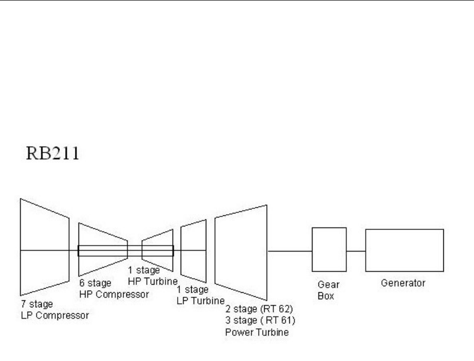
RB211 Background Information
The RB211 has evolved since its introduction in 1974. The RB211 was a successful follow-on
to the highly successful Avon used in utility, industrial power generation, cogeneration,
mechanical drives, and gas compression. The RB211 has a two-spool gas generator with a
EPRI Proprietary Licensed Material
Rolls-Royce Aero-Derivative Combustion Turbine Background
2-2
seven-stage low pressure compressor (LPC), six-stage high pressure compressor (HPC) driven
by a single-stage high pressure turbine (HPT), and a single axial stage, low pressure turbine
(LPT) which drives the LPC via an inner coaxial shaft, for a total of 5 pre-balanced modules.
The RB211 for power generation is derived from the three-spool aero RB211 flight engine in
which a final three-stage turbine drives a single-stage wide-chord fan.
Figure 2-1
Industrial RB211: Gas Generator and Free Power Turbine
The standard combustor is a single, fully annular, combustion chamber with eighteen air-spray
burners with atomizing fuel nozzles for liquid fuel. The DLE combustion system was introduced
in 1994 that resulted in a radical design change to the combustion module. The design change
includes nine reverse-flow radial combustors. Each combustion chamber contains a two-stage
combustion assembly with the air and fuel divided between the series-staged combustors. The
combustion module has the same physical dimensions as the standard module and is completely
upgradeable for all RB211 units without incurring a major overhaul. Combustors can be
configured for gas, liquid or dual fuel capability.
The RB211 incorporates an industrial type, free power turbine on a large pedestal base that
supports both the power turbine and the gas generator. The power turbine (for earlier models RT
56 and RT 62) is a two-stage free power turbine that uses journal bearings and mineral oil for
lubrication. Aimed at the pipeline/compressor drive application (oil and gas market) the power
turbine is design to rotate at 4800 to 4880 rpm. The RB211 is a hot end drive. For utility
applications, a reduction gearbox is required to reduce the speed to 1500 or 1800 rpm to drive a
four-pole generator for 50 and 60 hertz utility applications.
The new three-stage RT61 free power turbine, based on the aero Trent 800 engine’s turbine, is
designed for improved efficiency and is used with the uprated RB211. The new design
incorporates a three-stage, free power turbine but is lighter in weight with modular construction

EPR Proprietary I Licensed Material
Rolls-Royce Aero-Derivative Combustion Turbine Background
2-3
for ease in maintainability. This unit also requires a reduction gearbox in electrical utility
applications.
Several significant upgrades are available for RB211-24C and -24G gas generators which are
generally included in the RB211-24GT:
• DLE “short style” combustor for premix natural gas firing. The new “short style” reduces
acoustic resonance and dynamic pressure pulsations compared with the previous “long style”
DLE burner. The DLE retrofit can achieve less than 25 ppm of NOx and CO. There are over
80 units with over 1.5 million hours experience with the DLE combustor (may includes all
DLE styles). The DLE burner generally requires no manual tuning in the field.
• Dual fuel conversion for diffusion flame combustion of natural gas or fuel oil includes the
swirler burner for improved liquid fuel firing, as well as improved gas firing when it contains
condensable liquids
• Gas generator RB211-24G from -24C. Includes replacement of the HP turbine assembly,
including new directionally solidified blades with improved cooling. Either the user can
choose to maximize power and efficiency, or extend creep life of components by up to 50%
by derating the firing temperature 25 F (14 C).
• IP Compressor life improvement. A new stage 7 stator design and new stage 5 and 6
components reduce frettage due to aerodynamic excitation that ultimately could cause stator
breakup and downstream damage.
• Power turbine upgrade of either RT56 or RT62 for use with higher temperatures from the
RB211-24G gas generator. The upgrade generally includes blades, vanes, casings and
diffusers.
RB211 Horsepower Ratings
Engine type Horsepower Designation
-22 26,400 Coberra 264
-24A 29,600 Coberra 6256
-24C 34,000 Coberra 6456 / 6462
-24G 39,600 Coberra 6562
-24G DLE 40,500 Coberra 6762
-24GT 45,000 Coberra 6761

EPRI Proprietary Licensed Material
Rolls-Royce Aero-Derivative Combustion Turbine Background
2-4
RT 56 – (Cooper Bessemer) 56” Diameter, two stage, Reaction Turbine.
For the –22, -24A and –24C engines
RT 62 - (again Coopers) 62” Diameter, two stage, Reaction Turbine.
For the –24G and –24G DLE engines
RT 61 - (based on the Trent 800 aero engine) 61“ Diameter, three stage, Reactive Turbine
For the –24GT or uprated engine
RB 211 Maintenance Approach.
The time line for RB 211 maintenance, based on over 25 years of operating experience, is as
follows:
• 2,000 hour Inspection and Compressor soak wash
• 8,000 hour Inspection and borescope inspection
• 25,000 hour Mid Life Inspection & 04 Module Overhaul
• 50,000 hour Full Overhaul of the engine
(Inspection/overhaul details and workscope are described in the Appendix).
Both the 2,000 and 8,000 hour Inspections are carried out with the engine remaining in place.
The 2,000 inspection and soak wash can be accomplished in 4 to 6 hours, whereas the 8,000 hour
inspection with the borescope will need 8 to 10 hours of downtime. The standard turnaround
time for the RB211 gas generator is roughly 40-50 days.
For the Mid Life Inspection, the engine has to be removed from the berth but may be overhauled
at the site or depot. If spare 04 Module and IP Compressor Stator assemblies or access to ‘pool’
units is available, the work can be done on site. Otherwise, the engine is dispatched to the
Vendor’s overhaul shop to carryout this operation.
The Modular design of this engine allows for the swap of any Module once the engine is ‘bulk
stripped’ to its individual Modules. In the case of the 25,000 hour Mid Life, the 04 Module has
to be changed out. With the Vendors repair crew of two / three men, along with their tooling,
this task can be accomplished in three to four days, depending on client’s downtime window.
Two cranes (3 Tonne & 5 Tonne) with a lift height of 14 meters is a minimum requirement.
Historically, there are two areas in the RB 211 that have been life-limiting features. First, the
rubber dampening used in the inner shrouds of the I.P. Compressor Stage 5, 6 Stator
assemblies and the Stage 7 Stator or Outlet Guide Vane assembly degrades. This allows the
vanes to ‘flutter’ and leads to high cycle fatigue. Thus far, these assemblies have to be inspected
at 25,000 hours. Secondly, the ‘Z’ notch of the H.P. Turbine Blade outer shrouds suffers
from heat erosion and need to be repaired at this juncture. Failing that, the erosion will progress
to a point where the blades are beyond repair limits.

EPR Proprietary I Licensed Material
Rolls-Royce Aero-Derivative Combustion Turbine Background
2-5
Once the engine is removed from the berth, it can be placed on its transportation stand. At this
point the I.P. Turbine assembly can be uncoupled from its curvic coupling and removed. Then,
by use of the two cranes, the engine can be lifted into the vertical position and be placed nose
down on the lifting fixture. This allows for the removal of the 05 and the 04 Modules.
At this point the 01, 02 and 03 Modules are lifted and turned such that the assembly is now
resting on the 03 Module casing. This allows for the removal of the 01 and 02 Modules. Once
the 02 Module is removed the half casings can then be split, allowing access to the Stage 5 and 6
Stator assemblies for replacement.
The Stage 7 or OGV Ring assembly is the front part of the 03 module and can be replaced with
the spare assembly or ‘pool’ unit.
Rebuilding the engine is basically the reverse of the above procedure.
The 04 Module, along with the I.P. Stage 5,6 and 7 Stators, are then taken back to the overhaul
shop for full refurbishment to the latest Mod standard, to be placed back in the ‘pool’ or returned
to the Customer, if they were his spare assemblies.
One thing that should be emphasized here is that this experience is based on base load operation,
using gas fuel. Deviations from this scenario i.e. prolonged running with the bleed valves open,
will alter the inspection criteria. Other than these inspections clean fuel and clean air are a
must, to help prolong the life of the engine.
Turnaround Time and Costs
• As mentioned above, a Mid Life can be accomplished in the field with two men in 3 to 4
days.
• The 04 module will take approximately 40 days to fully recondition in the overhaul shop. In
the case of the IP Stage 5, 6 and 7 Stator assemblies, it will take 21 days to accomplish their
repair.
• Average cost of a Mid Life on the above components has been running in the region of
$ 345,000 to 375,000 US.
• For a full engine overhaul, the turntime is averaging 95 days and the costs are in the region of
$850,000 US.
Parts Life Upgrades
As discussed in the section - Maintenance Approach, the parts life issue was detailed. In the case
of the I.P. Compressor Stator assemblies, here are the latest Modifications these parts should be
refurbished to.

EPRI Proprietary Licensed Material
Rolls-Royce Aero-Derivative Combustion Turbine Background
2-6
I.P. Stage 5 Stator: to Mod. 1205. This will put hard facing on the vane feet and the
assembly will be re rubbered with machine injected, RTV 851
dampening medium.
I.P. Stage 6 Stator: to Mod. 1159, as above
Stage 7 (OGV Ring): to Mod. 1190, as above
Note: A redesigned OGV Ring was introduced thru Mod. 1249. This
assembly cannot be reworked from Mod 1117 or Mod 1190
assemblies. The redesigned vanes in this standard, feature full width
vane feet, hard facing and the RTV 851 rubber. New engines will
have this latest standard.
H.P. Turbine Blades: To combat the ‘shroud erosion’ extra cooling air and a better
protective coating was introduced to the blades.
Mod 1217: This introduced rear outer discharge nozzle (RODN) slots in the
package 1 combustor that delivered cooling air to the outer shroud of
the blades.
Mod 1131: H.P. Turbine Blades in MAR M002 material and coated with
Sermaloy ‘J’
Mini Flare Erosion: Burning and erosion of the Combustion Liner ‘mini flares’, although
not a life limiting feature, it will eventually cause problems to the fuel
nozzle head section.
These ‘mini flares’ are changed at the 25,000 hour refurbishment of
the 04 Module. Any minor flaking of the thermal barrier coating
(TBC) in the combustor can also be repaired at this time.
05 Module ‘Coking’: Another area of risk in the RB 211 has been oil ‘coking’ in the
scavenge and vent lines in the 05 module. This is cause by ‘crash’
stops, where the latent heat causes the residual oil in the bearing cavity
to coke up. Over time this coke completely blocked the main oil
scavenge line and oil was forced out the bearing cavity vent lines.
There are two ways to solve this problem.
First, review the unit’s shutdown experience and determining what can
be classed as a ‘cool’ stop. A ‘cool’ stop is where the engine is
brought down to idle RPM and remains at that speed for 5 to 8
minutes, before being shutdown. This gives the engine, and the close
coupled Power Turbine, a chance to ‘cool’ considerably from their
running temperature. On actual field tests it was found that on a crash

EPR Proprietary I Licensed Material
Rolls-Royce Aero-Derivative Combustion Turbine Background
2-7
stop the bearing cavity can see temperatures in excess of 400 degrees
in the ninety minutes following a crash stop. Whereas, on a cool stop
that cavity temperature only got up to just over 275 degrees. No oil in
the world can stand the former temperature, without laying down some
coke.
Secondly, to allow for the emergency stops – fire, gas in the building
etc. modifications were incorporated to get cool air into the 05 Bearing
Cavity after such an event. A Davis valve (Mod 1136) has shop air
connected to one inlet. When the engine suffers a crash shutdown, the
valve opens allowing shop air to pass, via the vent lines, into the
bearing cavity thus keeping it cool. Mod 1135 was also introduced to
allow a double vent of this cavity, and Mod 1123 fits a new connection
on the 05 module that a pressure gauge can be installed to set the shop
air pressure to the bearing cavity.
Service experience has shown that the combination of these
modifications has greatly reduced the amount of oil ‘coking’ seen in
this bearing cavity.
H.P. Compressor – Stage 5 Vanes:
There have been incidents of High Cycle Fatigue cracking on Stage 5
H.P. Compressor Vanes. It has been associated with Operators who
experience extremely cold ambient conditions. It has also occurred
when the bleed valves have been way out of their schedule, or the
bleed valve controller has seized.
Mod 1275 introduces the ‘spade foot’ stator to overcome this problem.
DLE Combustor Noise: Mod 1313 has gone a long way toward reducing the ‘noise’ in the
DLE combustor. This modification introduces Asymmetric Fuel
Injectors in the Primary combustion area.
However, 30% of the engines still had unacceptable levels of noise.
Asymmetric or split Secondary Fuel Injectors are now being
introduced
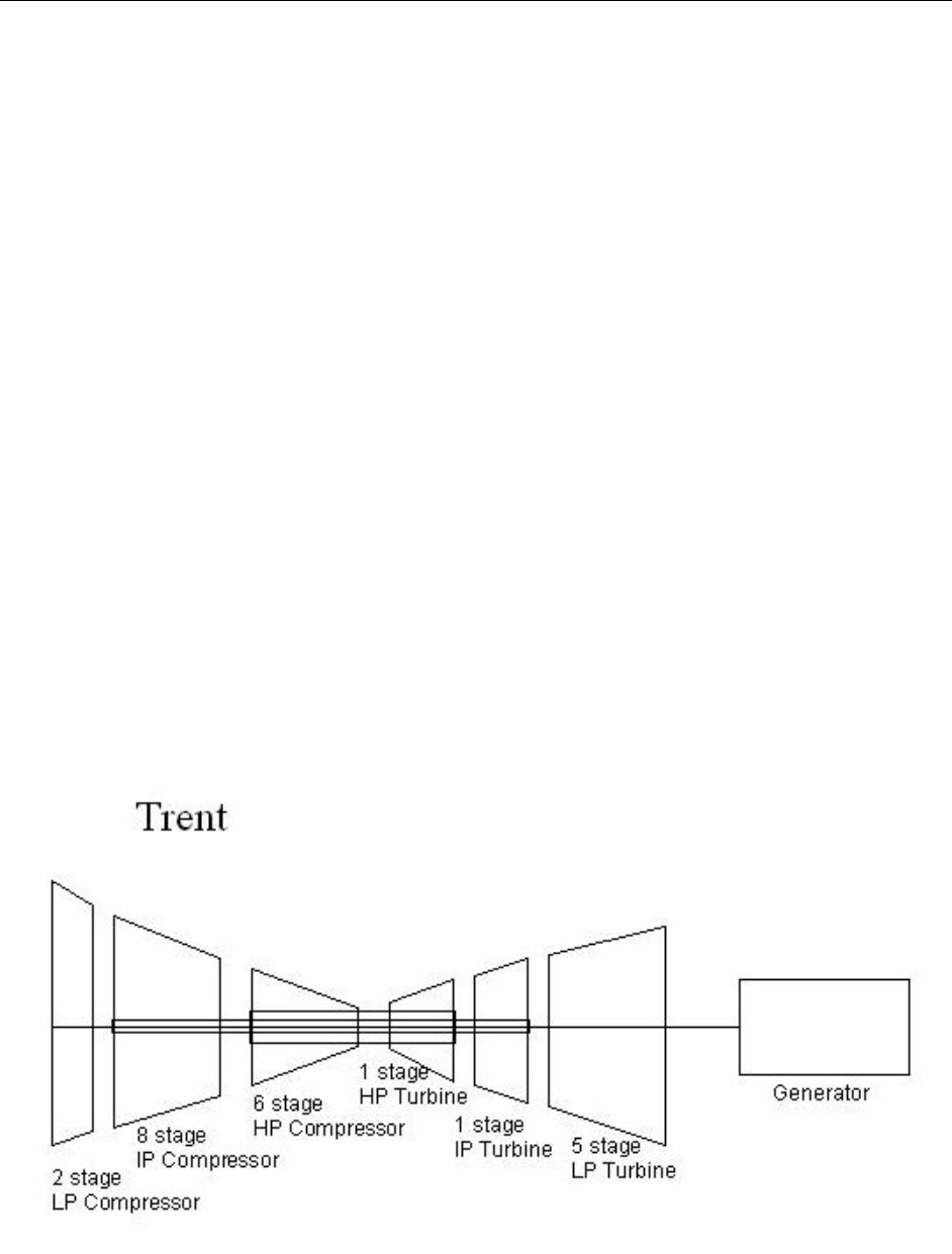
Trent Background Information
The industrial Trent design uses much of the aero Trent 800 engine core with the addition of a
new two-stage low-pressure compressor (LPC) in lieu of the high-bypass wide-chord fan on the
aero Trent. The main difference is the radical change to the DLE combustion system with eight
can-type combustors that are reverse-flow combustion design, radially mounted, perpendicular to
the axis of rotation. The DLE concept has been designed in the industrial Trent upfront.
Initially, the unit had difficulty meeting 25 ppm NOx emissions. A Wet Low Emission (WLE)
version has been developed and has been running in the UK. On-line emissions monitoring
EPRI Proprietary Licensed Material
Rolls-Royce Aero-Derivative Combustion Turbine Background
2-8
controls water usage to meet emission levels for changes in power demand and ambient
conditions.
The 8-stage intermediate pressure compressor (IPC) and the 6-stage high-pressure compressor
(HPC) are identical to the Aero Trent 800. The HPT and IPT are also single stages and identical
to the Aero 800 Trent. The low-pressure turbine LPT incorporates five stages, of which the first
three stages are identical to the Aero 800 Trent. The last two stages have longer blades because
the low-pressure shaft system is a direct drive system rotating at lower speed than the aero and
the expansion ratio is higher. This increase in expansion ratio is due to the need to extract all the
available energy for power production in the industrial turbine while the aero version retains
some of this kinetic energy to provide thrust.
Like GE’s LM6000, the low-pressure spool rotates at 3600/3000 rpm and is directly coupled to
the generator. No reduction gearbox is required. For 50-Hertz operation, the stagger angle on
the low-pressure compressor blades are changed slightly and the LPC rotates at 3000 rpm. The
industrial Trent is unique in that it is the largest aero-derivative combustion turbine in the world
at 51.2 MW and incorporates the three-shaft arrangement in both the compressor and turbine
sections. The industrial Trent is a hot end drive.
The three-shaft arrangement provides for better stage matching and performance since each
spool is optimized and allows for more efficient operation than an equivalent 2-spool turbine.
This design results in fewer stages, fewer airflow regulating provisions such as variable stators
and bleeds, a shorter turbine, and a high degree of modularity with its attendant benefits during
maintenance.
Figure 2-2
Industrial Trent

EPR Proprietary I Licensed Material
Rolls-Royce Aero-Derivative Combustion Turbine Background
2-9
The fundamental feature of the aero-derived turbine is its modularity. The industrial Trent
consists of 6 prebalanced and interchangeable modules. A module can be removed and replaced
with a module from the module pool and operations resumed without any other work being
necessary. This offers considerable benefits to a user in terms of reduced spares inventory,
increased availability, and the ability to defer refurbishment costs. Some users might choose to
send the entire engine back to a repair depot where the module changes can be made more easily.
There are over 10 units currently operating in power generation service, with at least 5 of those
in combined-cycle service. Other Trent engines have been sold for gas compression duty. At
about 40-42% efficiency, the Trent engine is currently the most efficient engine in its size
category of 50-58 MW.
The engine requires a 12 hour cool down cycle. It may use an External Heat Exchanger for
cooling air to blades and vanes.
Trent Maintenance Approach
As with the RB211, the industrial Trent engine package is designed for ease of maintenance.
Currently, all Trent engines are maintained under long-term maintenance contracts. Scheduled
maintenance occurs as follows:
• 4,000 Hour (or 6 month) Intermediate Maintenance: boroscope inspection of hot section
components
• 8,000 Hour (or annual) Annual Maintenance: boroscope inspection, plus functional checks of
gas turbine package systems and safety checks of equipment and control system
• 25,000 Hour HP/IP Core Replacement: includes annual maintenance, plus
refurbishment/replacement of worn parts and re-coating of parts as required.
• 50,000 Hour Whole Engine Replacement: includes annual maintenance, plus a total engine
strip and refurbishment of all parts, which extends engine life through a second 50,000 hour
interval.
Modules can be swapped out in the field in as little as 72 hours. The unit can be easily split into
3 portions: the LP compressor, the HP/IP core, and the LP turbine.
Avon Background Information
The industrial Avon engine, introduced in 1964, has seen more than a 44% increase in power
rating and improvement of over 14% in efficiency in the last 40 years. The current model, the
Avon-2656, produces 15.6 MW at 30.3% efficiency. Cumulatively, the Avon in its various
applications has more than 1,200 installed units with over 53 million operating hours. In
electrical power generation, there are approximately 529 units with over 11 million operating
hours. A recently announced upgrade will provide an additional 6-8% capacity and about 3
percentage points higher efficiency.

EPRI Proprietary Licensed Material
Rolls-Royce Aero-Derivative Combustion Turbine Background
2-10
The 17 stage gas generator provides a compression ratio of 8.8:1 and is driven by a 3 stage
turbine. The 2 stage power turbine drives a 4-pole generator at 1500-1800 rpm, similar to the
RB211.
Although some new units are sold each year, the product line appears to be phasing out for
electrical generation applications. Rolls-Royce provides continuing support for the relatively
large existing fleet. Furthermore, several upgrades have been implemented: the swirler burner
for improved handling of liquids in otherwise gaseous fuel (similar to the upgraded diffusion
burner for the RB211), and improved components for increased power and efficiency. Even
though a DLE combustor was previously announced for the Avon, that work is apparently not
going forward. Although standardized skid-mount packages are being developed for the RB211
and Trent, the effort for a highly-engineered Avon package is not anticipated.
Unlike the maintenance schedule for the RB211 and Trent engines, the Avon is refurbished at
roughly 30,000 and 60,000 hours, while undergoing a comprehensive overhaul at 90,000-
100,000 hours. The standard turnaround time is 40 days.
Pedigree Matrix for the RB211 and Trent 60 Engines
This section provides a review of the Pedigree Matrix developed for the Rolls-Royce RB211 and
Trent industrial combustion turbine product line currently relevant for new electrical generation
projects. The Pedigree Matrix is structured to show the distinguishing characteristics of the
selected models, and the significant or major design changes from each model.
The Pedigree Matrix for the Rolls-Royce RB211-6562, RB211-6761 (Uprate), and the Trent 60
current production industrial units is provided in the following table. Items with gray
background highlight areas of significant design changes compared with previous designs from
the manufacturer.

EPR Proprietary I Licensed Material
Rolls-Royce Aero-Derivative Combustion Turbine Background
2-11
Table 2-1
Pedigree Matrix: Rolls-Royce RB211-6562, RB211-6761, Trent 60 (DLE and WLE) Engine Design Characteristics
Design
Characteristic
RB211 – 6562
(RB211-24G Gas Generator
with RT62 Power Turbine)
RB211 – 6761
(RB211-24GT Gas
Generator with RT61 Power
Turbine)
Trent 60 DLE
(Derivative of AERO 800 on
Boeing 777 and Airbus
A330)
Trent 60 WLE
(Derivative of AERO 800 on
Boeing 777 and Airbus
A330)
Reliability, Maintainability, Durability
Comments
Distinguishing
Features
Standard Annular
Combustor
(Non - DLE) 5 Modules,
Free Power Turbine,
External Gearbox
DLE Combustor Option
More efficient Power
Turbine
DLE Combustor, 3 Spools
with 6 Modules , LP
Turbine drives Generator
and LP Compressor
Directly
Std. Diffusion Combustor
with Water Injection, 3
Spools with 6 Modules ,
LP Turbine drives
Generator and LP
Compressor Directly
Fully interchangeable modules with advanced
condition monitoring techniques allows high levels
of availability with a minimum of downtime.
Year of
Introduction
1993 (DLE option in 1994)
Original RB211 Model 1980
RB211-6556 Model 1990
(-24C GG with RT56 PT)
2000
RB211-6762 Model (-24G
Gas Generator and
RT62 Free Turbine) 1999
1997
(was initially named Trent 50) 2002
Approximate
Fleet Size
240 RB211-24G
Total of 400+ RB211
incl. 260+ mech. drive and
80+ Power Generation
68 DLE engines.
All Existing Units can be
Retro-Fitted
New “short style” DLE
reduces dynamics
10+ Total Operating
1 in Ontario, Canada
5 in the UK
1 in Denmark
5 Ordered for Power
Generation
1
Four (4) development
engines running
Designed for maintenance with full modular
features and five interchangeable modules
Designed with condition monitoring system and
multiple borescope ports
Modules are light weight and easily transportable
Output, ISO, Gas
Fuel
28.8 MW (50 Hz or 60 Hz)
27.5 MW (DLE) 32.1 MW (50 Hz or 60 Hz)
51.5 MW (50 Hz)
51.7 MW (60 Hz)
(58 MW max.)
58 MW (50 Hz)
58 MW (60 Hz)
Utilized on 220 onshore applications and 120
offshore applications
Heat Rate, ISO,
LHV
9,226 Btu/kWh
(9,734 kJ/kWh)
9,415 Btu/kWh DLE
(9,933 kJ/kWh)
8,680 Btu/kWh
(9,158 kJ/kWh)
8,104 Btu/kWh
(8,488 kJ/kWh) 50 Hz
8,138 Btu/kWh
(8,530 kJ,/kWh) 60 Hz
Approx. 8,400 BTU/kWh
(8,900 kJ/kWh)
Firing
Temperature
2128 oF
1164 oC
2250 oF
1232 oC
HPT Inlet 2250 oF
1232 oC
HPT Inlet 2250 oF ?
1232 oC ?
Thermal
Efficiency, ISO,
Gas Fuel
36.2% 39.3% 42.1% 41.0%
Industry leading efficiency and reliability are
achieved by incorporating the latest technological
advances proven in the flight engine.
Efficiency and flexibility makes this design also
well-suited for pipeline operation

EPRI Proprietary Licensed Material
Rolls-Royce Aero-Derivative Combustion Turbine Background
2-12
Design
Characteristic
RB211 – 6562
(RB211-24G Gas Generator
with RT62 Power Turbine)
RB211 – 6761
(RB211-24GT Gas
Generator with RT61 Power
Turbine)
Trent 60 DLE
(Derivative of AERO 800 on
Boeing 777 and Airbus
A330)
Trent 60 WLE
(Derivative of AERO 800 on
Boeing 777 and Airbus
A330)
Reliability, Maintainability, Durability
Comments
Exhaust Flow,
ISO, Gas Fuel
208.7 lb/sec
94.5 kg/sec
207.4 lb/sec
94.0 kg/sec
351 lb/sec
159 kg/sec
358 lb/sec
163 kg/sec
Exhaust
Temperature,
ISO, Gas Fuel
916 F
492 C
941 F
505 C
LPT Outlet Temp 801 F
427 C
LPT Outlet Temp 813 F
434 C
Compression
Ratio -
Compressor
Discharge to Inlet
20.8:1 21.0:1 35.0:1 35.5 : 1
Output End
(Drive End)
Hot End Driven by RT 62
power turbine through
reduction gearbox @
4880/1800/1500
Hot End RT61 Power Turbine
driven through reduction
gearbox 4800/1800/1500
Hot End directly driven by
LPT at 3600/3000
(Stagger on LPC blades
changed for 3000 rpm
operation)
Hot End directly driven by
LPT at 3600/3000
(Stagger on LPC blades
changed for 3000 rpm
operation)
Compressor
Stages
7 stage LP/IPC
6 stage HPC
7 stage LP/IPC
6 stage HPC same as Aero
Trent 700
LPC 2 Stages
IPC 8 Stages
HPC 6 Stages
LPC 2 Stages
IPC 8 Stages
HPC 6 Stages
Extractions Bleed Valves Rear IPC
Bleed Valves Center HPC
LPC 18 Exit Bleed Doors
IPC 4 Bleed Doors Stage 8
HPC 3 Bleed Doors Stage 3
LPC 18 Exit Bleed Doors
IPC 4 Bleed Doors Stage 8
HPC 3 Bleed Doors Stage 3
Accessories Gas / Air or hydraulic starters
are available
Anti-Icing feature deleted.
Continuous pulse air filter
used to minimize icing.
Gas / Air or hydraulic starters
are available
Gearbox mounted main
lubrication oil pump and the
starter/clutch assembly drive
shafts
Speed probes and manual
rotation feature
Gearbox mounted main
lubrication oil pump and the
starter/clutch assembly drive
shafts
Speed probes and manual
rotation feature
The inlet contains two rings of 20 nozzles each;
the inboard ring is used for off-line water wash
and the outboard ring is used for on-line water
washes.
Bearings,
Number and
Type. (all)
Continuously
Lubricated
IP Rotor 3 Bearings
HP Rotor 3 Bearings
Thrust Bearing Double Ball
(Duplex)
IP Rotor 3 Bearings
HP Rotor 3 Bearings
Thrust Bearing Double Ball
(Duplex)
3 Thrust (Ball) Bearings
5 Roller (Cylindrical Roller
Bearings
3 Thrust (Ball) Bearings
5 Roller (Cylindrical Roller
Bearings
Uses aircraft anti-friction rolling element bearing
lubricated by synthetic fluids. The industrial
power turbine uses mineral oil and requires
separate oil system
Starting Times:
to breaker
closure
to full load
Total time
8 Minutes to purge and
warm-up
2 minutes to baseload
10 Minutes Total for Start
8 Minutes to purge and
warm-up
2 minutes to baseload
10 Minutes Total for Start
16 minutes including Purge
and Warm-up;
10 minutes to Baseload
25-30 minutes Total for Start
10 minutes fast start to full
load
(no life limitation)

EPR Proprietary I Licensed Material
Rolls-Royce Aero-Derivative Combustion Turbine Background
2-13
Design
Characteristic
RB211 – 6562
(RB211-24G Gas Generator
with RT62 Power Turbine)
RB211 – 6761
(RB211-24GT Gas
Generator with RT61 Power
Turbine)
Trent 60 DLE
(Derivative of AERO 800 on
Boeing 777 and Airbus
A330)
Trent 60 WLE
(Derivative of AERO 800 on
Boeing 777 and Airbus
A330)
Reliability, Maintainability, Durability
Comments
Starting Means Hydraulic Starter via radial
drive gearbox on HPC
Hydraulic Starter via radial
drive gearbox on HPC
Hydraulic Starter
(250 kW motor)
Hydraulic Starter
(250 kW motor)
Compressor
Variable Stages 1 stage of 34 VIGV's
1 stage Solid Variable Inlet
Guide Vane (VIGV)
Revised VIGV Control
RVDT (Rotary Variable Diff.
Transformer)
IGVs in Front of the LPC
IPC has Stage 1 VIGV's
IPC has 2 rows of VSVs
HPC has no variable stators
IGVs in Front of the LPC
IPC has Stage 1 VIGV's
IPC has 2 rows of VSVs
HPC has no variable stators
Compressor
Blades
LPC Titanium Blades coated
with Sermetel "W"; HPC
Blades Stage 1 Ti, Stg 2-6
Stainless Steel
LPC Blades-Titanium
IPC Blades-Titanium
HPC Blades 1,2 - Titanium
HPC Blades 3,4,5 - Nimonic
LPC Blades-Titanium
IPC Blades-Titanium
HPC Blades 1,2 - Titanium
HPC Blades 3,4,5 - Nimonic
Compressor
Vanes
First stage (34) VIGV's,
Stages 2 thru 7 fixed on IP
Compressor. 6 fixed stages
of stators in the HP
Compressor
Redesigned Stage 5 stator,
Hard-faced stage 6 stator,
First stage (34) VIGV's,
Stages 2 thru 7 fixed on IP
Compressor. 6 fixed stages
of stators in the HP
Compressor Revised OGV
ring ( Stage 7) fitted to IP
Compressor.
LP - 1 variable 2 fixed
IP 2 Variable 7 fixed HP 8
fixed
LP - 1 variable 2 fixed
IP 2 Variable 7 fixed HP 8
fixed
Compressor
Rotor
IPC Welded Drum SS & Ti
HPC Welded Drum Ti Trent 800 HPC Compressor
LPC Operates at 3600 or
3000 RPM without the need
for a reduction gear. The
LPC blades are changed for
50 Hz Operation.
LP - 2 Stage IP - 8 Stage
HP - 6 stages
LPC Operates at 3600 or
3000 RPM without the need
for a reduction gear. The
LPC blades are changed for
50 Hz Operation.
LP - 2 Stage IP - 8 Stage
HP - 6 stages
Compressor
Casings
Air Intake Al Alloy Casting
IPC Casing Al Alloy Casting
HPC 12% Cr SS
Single Skin Inlet Bullet-nose
with the elimination of anti-
icing (-24G and -24GT)
LPC Outer Case is Split to
Access the LPC Stators
LPC Outer Case is Split to
Access the LPC Stators
Turbine Casings Turbine Casing Nimonic PE.
16
Single Piece Frame Turbine
Support

EPRI Proprietary Licensed Material
Rolls-Royce Aero-Derivative Combustion Turbine Background
2-14
Design
Characteristic
RB211 – 6562
(RB211-24G Gas Generator
with RT62 Power Turbine)
RB211 – 6761
(RB211-24GT Gas
Generator with RT61 Power
Turbine)
Trent 60 DLE
(Derivative of AERO 800 on
Boeing 777 and Airbus
A330)
Trent 60 WLE
(Derivative of AERO 800 on
Boeing 777 and Airbus
A330)
Reliability, Maintainability, Durability
Comments
Turbine Vanes -
HP
Mar-M-002, Sermaloy J
coating, air-cooled
Mar-M-002, Sermaloy J
coating, air-cooled
MarM002, Pt-Al coating, air-
cooled
Identical to the Aero 800
except for minor film cooling
modification
MarM002, Pt-Al coating, air-
cooled
Identical to the Aero 800
except for minor film cooling
modification
Typically performs Hot Gas Path Inspections at
25,000 fired hours and turbine overhauls at
50,000 fired hours
Turbine Vanes -
IP C1023, Sermaloy J coating C1023, Sermaloy J coating MarM002, Pt-Al coating
Identical to the Aero 800
MarM002, Pt-Al coating
Identical to the Aero 800
Turbine Vanes -
LP
(see Power Turbine
description)
(see Power Turbine
description)
LPT-1,2 MarM002
LPT-3 C1023
LPT-4, 5 IN738LC
LPT-1,2 MarM002
LPT-3 C1023
LPT-4, 5 IN738LC
Turbine Blades -
HP
HPT-1 CMSX4 DS, Sermaloy
1515 coating, air-cooled
(upgrade from RB211 -24C)
Identical to the Aero RB211-
524G/H-T
HPT-1 CMSX4 Single
Crystal,
Sermaloy J Coating, air-
cooled
(was MarM002 with Pt-Al for -
24G prior to upgrade)
Identical to the Aero 800 - Air
Cooled
HPT Blades CMSX4, Single
Crystal
Platinum-Aluminide Coating
(cooling air from HPC-6)
Identical to the Aero 800 - Air
Cooled
HPT Blades CMSX4, Single
Crystal
Platinum-Aluminide Coating
(cooling air from HPC-6)
Uses blades directly from Trent 800, minor
changes in the film cooling pattern on the HP
Nozzle
Turbine Blades -
IP
Stage 1 LPT Blades CMSX4
(Directionally Solidified),
Coated with Sermaloy 1515
(upgrade from RB211 -24C)
Stage 1 LPT Blades CMSX4
(Directionally Solidified),
Coated with Sermaloy 1515
Identical to the Aero 800 -
Uncooled
IPT Blades RR3000,
directionally-solidified
(proprietary nickel-based
super-alloy)
Platinum-Aluminide Coating
Identical to the Aero 800 -
Uncooled
IPT Blades RR3000,
directionally-solidified
(proprietary nickel-based
super-alloy)
Platinum-Aluminide Coating
Turbine Blades -
LP
(see Power Turbine
Description)
(see Power Turbine
Description)
The first three stages of the
LPT are identical to Aero 800;
the last two stages have
increased expansion ratio to
extract all of the available
energy from the gas stream
for power production, having
larger gas path area and a
lower exit Mach Number than
the Aero 800
LPT-1 MarM002 LPT-2,3
IN713 LPT-4, 5 IN718

EPR Proprietary I Licensed Material
Rolls-Royce Aero-Derivative Combustion Turbine Background
2-15
Design
Characteristic
RB211 – 6562
(RB211-24G Gas Generator
with RT62 Power Turbine)
RB211 – 6761
(RB211-24GT Gas
Generator with RT61 Power
Turbine)
Trent 60 DLE
(Derivative of AERO 800 on
Boeing 777 and Airbus
A330)
Trent 60 WLE
(Derivative of AERO 800 on
Boeing 777 and Airbus
A330)
Reliability, Maintainability, Durability
Comments
Turbine Rotor (see Power Turbine
Description)
(see Power Turbine
Description)
HPT 1 Stage, IPT 1 Stage
LPT 5 Stages with aft 2
stages functioning as a
Power Turbine
HPT 1 Stage, IPT 1 Stage
LPT 5 Stages with aft 2
stages functioning as a
Power Turbine
PT Free Power
Turbine
(Industrial Type)
RT62 Introduced 1982;
Two stage PT with industrial
thrust & journal bearing
RT61 Introduced in 1997;
Three Stage PT unit with
industrial thrust and journal
bearings
(see LP Turbine Description) (see LP Turbine Description)
PT Casings
Pedestal base that supports
both PT & GG assemblies
Strutless inlet & exhaust
diffusers
Lighter weight unit with
modular construction (5) (see LP Turbine Description) (see LP Turbine Description)
PT Nozzle Vanes Stage 1 vanes Rene' 80
Stage 2 vanes U - 500
46 First Stage Nozzle Vanes
Rene' 80
60 Second Stage Nozzle
Vanes U-500
60 Third Stage Nozzle Vanes
N-155
(see LP Turbine Description) (see LP Turbine Description)
PT Rotor
Shaft AISI 4340 high tensile
Ni Cr Mo Alloy Steel
(Overhung design)
Shaft AISI 4340 high tensile
Ni Cr No Alloy Steel
(Overhung design)
(see LP Turbine Description) (see LP Turbine Description)
PT Rotor Blades
1st stage blades: Rene' 80
(83 count)
2nd stage blades U-500
(83 count)
1st Stage Blades:Rene' 80
(83 count)
2nd Stage Blades U-500
(79 count)
3rd Stage Blades N-155
(71 count)
Interlocking, shrouded blades
with honeycomb tip seals
(see LP Turbine Description) (see LP Turbine Description)
PT Rotor Disks Both disks INCO 901 Ni Co
Base Alloy
Disks are joined with Curvic
Couplings
Inco 901
(see LP Turbine Description) (see LP Turbine Description)
PT Bearings &
Seals
Kingsbury type Thrust
Bearing (1)
Tilting Pad type Journal
Bearings (2)
Labyrinth Seals (SS)
Kingsbury Type Thrust
Bearing (1)
Tilting Pad Type Journal
Bearings (2)
Labyrinth Seals (SS)
(see LP Turbine Description) (see LP Turbine Description)

EPRI Proprietary Licensed Material
Rolls-Royce Aero-Derivative Combustion Turbine Background
2-16
Design
Characteristic
RB211 – 6562
(RB211-24G Gas Generator
with RT62 Power Turbine)
RB211 – 6761
(RB211-24GT Gas
Generator with RT61 Power
Turbine)
Trent 60 DLE
(Derivative of AERO 800 on
Boeing 777 and Airbus
A330)
Trent 60 WLE
(Derivative of AERO 800 on
Boeing 777 and Airbus
A330)
Reliability, Maintainability, Durability
Comments
Distinguishing
Features
(from earlier
models)
RT62 Power Turbine
Single Crystal Turbine Blades
(HPT & IPT)
Radial Can-Annular DLE
Combustor
The Radial DLE combustor is
a radical departure from the
aero version with DLE
designed in up front
Phase 5 annular combustor
(similar to Aero Trent)
Number of
Combustors
Single fully annular
combustor with steel outer
casing and NIMONIC 263
liner
Eighteen fuel nozzles
Series Staged 9 Can Type
DLE radially mounted pre-mix
lean burner chambers with a
single fuel injector for each
can
8 Can Type DLE with reverse
flow Perpendicular to the Axis
of Rotation
3 stage lean burn DLE
Combustor Materials-INCO
625 and Haynes 230
24? fuel burners on standard
Phase 5 Combustor
Dual Fuel Capable
Emission
Capabilities 170+ ppmv NOx @ 15% O2
DLE 25 vppm NOx on gas
42 vppm NOx on liquid fuel
with water injection
25 ppm CO
25 ppmv NOx, 25 ppmv CO
at 15% O2 on gas
Water injection is required for
LF operation
NOx - 25 vppm
CO < 32 vppm
(diffusion burner with water
injection)
DLE combustor uses 2 stages with precise control
of the fuel flow division rather than trying to
control the air flow
RB211 has over 250,000 DLE fired hours of
operation
Emission
Abatement
Configuration
Standard combustor - DLE
retrofit available?
DLE Combustion System -
Standard Combustor
Available?
DLE Combustion System Water injection thru combined
fuel / water injectors RB211 uses WI for NOx control on LF
Control System Flexitrend by En-Tronic Flexitrend by En-Tronic Woodward Woodward
Utilizes time proven control systems with digital
electronics
Proven operation in remote areas with operator-
less control and protection.
Options
Integrated auxiliary drive fro
lube oil, seal oil and hydraulic
systems

EPRI Proprietary Licensed Material
3-1
3
RELIABILITY, AVAILABILITY AND MAINTAINABILITY
Data Analysis: Rolls-Royce Aero-derivative Engines
This chapter provides statistical evaluation of the Reliability, Availability, and Maintainability
(RAM) performance of the Rolls-Royce Avon, RB211, and Trent machines in power generation
applications. The fleet is represented by units that report to the Operational Reliability Analysis
Program (ORAP) managed by Strategic Power Systems (SPS). RAM data is reported to ORAP
on a voluntary basis and therefore not all units in a particular fleet are represented. To the extent
that the data is based on a substantial number of the fleet units in a particular category, the results
are representative statistical sampling of that fleet. See Appendices for details about ORAP and
RAM statistics.
Simple cycle plant statistics are provided in this report because the focus is on the combustion
turbine. The impact of the combustion turbine and its interaction with the operation and
maintenance of the plant is considered the prime issue. Other studies examine the balance of
plant RAM for combined cycles, including the HRSG and steam turbines.
For most models, the majority of the units reporting in the ORAP database are baseload electric
or cogenerators, although the smaller capacity models also have a substantial number of units in
simple cycle mode for peaking duty. The units currently performing cycling duty formerly were
baseloaded units and have recently transitioned to cycling duty. At a site with a single unit the
tendency of the cycling unit is to shutdown for the weekend. At sites with multiple units the
tendency of the cycling units is shutdown on a rotating schedule. Some of the units run for
longer fired hours per start, then shutdown on the third night and restart in the morning to
minimize the total number of on-off cycles.
The maintenance philosophy implemented by the OEMs and Users has a direct impact on RAM
and is the leading cause of a plant’s unavailability. The demand and use of a combustion turbine
greatly influences these decisions but unavailability is a User/OEM controlled parameter of when
and how scheduled and unscheduled maintenance is performed. For instance, plants that are
simple cycle peakers may have less incentive to minimize the time required to perform scheduled
maintenance, and therefore have lower availability than baseload units of the same model. For
peakers, reliability and availability are most critical during seasons in which electricity prices are
at a premium.
This report contains a summary of RAM statistics available at the time of publication. More
detailed statistics, including future annual updates, are available to current project 80.002 funders
via electronic download from www.epri.com. Login is required. Proceed to Program 80 in the

EPRI Proprietary Licensed Material
Reliability, Availability and Maintainability
3-2
Generation area, Strategic Generation Options and go to Newsletters/ Program Updates under the
Research Area Updates section in the left sidebar.
RAM Statistics: Avon, RB211 and Trent - All Duties
Data from the Operational Reliability Analysis Program (ORAP) was utilized to provide
statistics on Rolls-Royce engines. The following table summarizes the characteristics for the
Rolls-Royce fleet as represented by the units reporting to ORAP. The statistics are for all units
reporting that meet SPS criteria for inclusion in the database for a particular year. As such, they
are a subset of Rolls-Royce entire operating fleet. 2005 is the first year in which Rolls-Royce
data is available in ORAP; therefore trending over time is not available.
Table 3-1
RAM Statistics: Fleet Characteristics for Avon, RB211, and Trent
Avon RB211 Trent
Time Period 1 Year: 2005 1 Year: 2005 2 Years: 2004, 2005
No. of Units 6 10 4, 8
Unit-Years 4.2 8.1 11.1
Period Hours 36,790 70,960 97,240
Fired Hours 29,700 45,250 18,860
Service Factor 81% 64% 19%
Units that report for less than 100% of the time period result in partial unit-year data. Units
reporting less than 70% of a calendar year are typically excluded from the data set. Note that
this data set represents a limited sampling of engines in each model type and therefore the RAM
statistics may not accurately represent the larger fleet.
The following table summarizes the combined duty RAM statistics for the Rolls-Royce fleet
reporting to ORAP.

EPR Proprietary I Licensed Material
Reliability, Availability and Maintainability
3-3
Table 3-2
RAM Statistics for Roll-Royce Avon, RB211 and Trent Engines – All Duties
Model
& Year Availability
(%) Reliability
(%) Service
Factor
(%)
Service
Hours/Start Starting
Reliability
(%)
Average
Load
(MW)
Forced
Outage
Factor
(%)
Scheduled
Outage
Factor (%)
Unscheduled
Outage
Factor (%)
Mean
Time
Between
Failure
(Hours)
Mean
Time
To
Repair
(Hours)
Avon
2005 97.5 99.4 81 215 93 N/A 0.6 1.7 0.2 423 3
RB211
2005 83.4 86.8 64 159 97 20 13.2 2.9 0.5 285 453
Trent
2004 82.1 86.1 24 28 82 47 13.9 3.9 0.1 59 18
Trent
2005 75.0 88.7 17 14 87 46 11.3 4.9 8.8 38 35
Average values compiled from Operational Reliability Analysis Program (ORAP). 2005. MTBF and MTTR include both forced and unscheduled Maintenance
hours. High MTBF of RB211 due to a single event requiring 4,416 hours before restored to operation.

EPRI Proprietary Licensed Material
Reliability, Availability and Maintainability
3-4
Additional RB 211 Operating Statistics
The following table provides average Reliability and Availability statistics for a limited number
of RB 211 engines based on a one-year operational study. Statistical values are from sources
other than ORAP and have not been verified.
Table 3-3
Additional RB 211 Operating Statistics
Type # Number of Units Service Factor Availability % Reliability %
24 A 9 56.4 90.2 98.3
24 C 21 61.07 90.2 98.6
24 G 13 52.26 98.0 99.5
24G DLE 16 71.8 95.9 99.8
Avg. of Fleet 93.6% 99.0%
Avg. of -24G & DLE 97.0% 99.8%
RAM Assessment
The typical benchmark for mature heavy-duty and aero-derivative engines is 99% reliability,
94% availability and 95% starting reliability, on average. The Avon exceeds these minimum
expectations; however, the RB211 and Trent machines, as represented by these particular fleets
reporting to ORAP, do not meet benchmark values. Furthermore, the Trent does not meet
expectations for starting reliability. Since the Trent engines in this sample appear to be in
peaking service, starting reliability is a critical factor as well. Again, caution is advised since the
number of units in the ORAP statistical sample is relatively small, particularly for the Avon and
RB211 engines. The single year operational study data on RB211 engines shows more favorable
availability and reliability statistics, particularly for the later sub-model type G.
Conclusion
The aero-derivatives are generally classified as “under 50 MW”. The industrial Trent breaks that
barrier and is the word’s largest aero-derivative combustion turbine at 51.2 MW. The heritage of
the aero-derivatives leads to the inherent development of flexible, high power density, and highly
efficient industrial combustion turbines. By their very nature they are generally more complex
and more exotic than the frame type (heavy duty) industrial combustion turbine. The frame type
industrial combustion turbine, however, is adopting much of the aero technology to the point that
there is a similarity of the flow paths cooling schemes, coatings, and combustion technologies.
The limiting factor is not the transfer of technology but in the manufacturing of frame size
components from the aero size components.

EPR Proprietary I Licensed Material
Reliability, Availability and Maintainability
3-5
The review of the frame pedigree matrices in a previous EPRI Report TR-114081, “Gas Turbine
Design Evolution and Risk” clearly shows a high degree of commonality between the design of a
frame unit and an aero-derivative unit. But at the same time, they are extremely different. One
cannot operate a frame unit like an aero-derivative and visa versa. Also, the modularity with
small sizes and lighter weights promote “repair by replacement” philosophy as part of the aero-
derived heritage. The User must accept the “repair by replacement” philosophy and understand
the inherent design features of the aero-derivatives. The prime features are multi-spools and
multiple main rolling element shaft bearings. The lubrication system uses synthetic lubricating
fluid and the turbine requires high degree of purity and cleanliness. The aero-derivative
combustion turbine with more variable geometry, control devices, and accessories experiences
approximately twice the number of forced outages as the frame units. But, because of the aero-
derivative’s inherent maintenance features, the turbine can generally be restored to operation in
half the time as a similar frame outage. Therefore, the net downtime is the same for aero-
derivatives and frame turbines (i.e. the Forced Outage Factors (FOF) are roughly equivalent).
The main difference is the downtime associated with major outages requiring disassembly and
repair of the frame units on site.
The inherent design of the aero-derivative industrial combustion turbine is generally more
complex and exotic and has more parts and more moving parts to fail. The aero-derivative
industrial combustion turbine also has more instrumentation to allow for designed control and
protection. Due to its heritage, it is easier to repair and return to service.
The aero-derivative’s greatest asset is its modularity. With complete interchangeability of like
modules and line replaceable components, it relies on a maintenance philosophy called “repair
by replacement”. The Rolls-Royce aero flight engines have a long history of being the world’s
most powerful and reliable turbines. The industrial versions of these engines are continuing that
tradition and are some of the world’s most powerful and reliable industrial turbines.
The features outlined below represent the major differences between aero-derivatives and frame
units, other than their power density:
• Modularity, promoting repair by replacement
• Aircraft heritage for fast starting and tolerance to cycling
• Ease of maintenance
• High performance and efficiency
Some long-term problems associated with aero-derivatives include:
• Bearing and seals requiring monitoring and conditioning equipment
• DLE combustion systems requiring refinement to meet stringent objectives
• Compressor sensitivity to stall or surge
Lastly, the repair cycle and actual costs to achieve high availability must be accounted for in life
cycle evaluations. The cost of membership into a lease program, the cost of leased turbine
usage, and the cost of repair to the Users turbine has to be considered and assessed by the Users.

EPRI Proprietary Licensed Material
4-1
4
BIBLIOGRAPHY
Literature Citations
• “New applications for Trent”, Turbomachinery International, Sept/Oct 2005, pp 9-12.
• T. Scarinci and C. Barkey (Rolls-Royce Canada), “Dry Low Emissions Technology for
the Trent 50 Gas Turbine”, paper presented at Power-Gen Europe, Barcelona, Spain, May
2004.
• “Dedicated facilities built for Avon and RB211 overhauls and repairs” (Rolls Wood
Group in Aberdeen, Scotland), Gas Turbine World, Apr/May 2004, pp 24-26.
• “Rolls-Royce Expands Allison Turbine Users Association”, Turbomachinery
International, Nov/Dec 2002 pp 30-31.

EPRI Proprietary Licensed Material
A-1
A
KNOWN ISSUES
Table A-1
Listing of Known Issues for Rolls-Royce Units
Issue Symptom Comments
Ancillary Package
Design Numerous Deficiencies Cooper Bessemer, now part of Rolls-Royce,
packaged the unit as a Coberra 6256 and
then, with the higher powered machines, the
Coberra 6562 unit. The troublesome Lube
Oil skid problems have now been resolved.
Westinghouse also offered a package design
known as the EconoPac concept. While the
turbine performed very well, there were
problems with some aspects of the initial
package design, which were corrected by
RR.
Digital Control
System Upgrade Software and card
problems The new Entronics, (now part of Rolls-
Royce), control system required software
and card changes with introductory units (as
with any new product introduction that has
not yet been widely tested)
DLE Combustion Acoustics Initially the DLE technology produced
unacceptable acoustic problem within the
DLE combustion system. Modifications and
testing are being introduced to eliminate
these problems.
DLE Combustion -
Trent NOx Emissions The Trent DLE has had difficulty meeting 25
ppm NOx emissions guarantees. A new DLE
design is expected in 2003 to resolve the
issue.
Combustor
Module Casing -
Trent
Gas Leakage –
Maximum Power
Derating
A revised casing for the Trent DLE
combustor module is expected in 2003 to
resolve this issue. Until then the maximum
pressure ratio during cold day operation is
limited.
General - Trent Numerous Deficiencies Numerous problems occurring on the lead
machine (Whitby Cogen) in 1996-1999 –
resolutions indicated. Details unknown.

EPRI Proprietary Licensed Material
B-1
B
RB 211 MAINTENANCE SCOPE
RB 211 - 2,000 Hour Inspection
• Carry out a soak wash of the engine’s compressor.
• On completion of the above;
− Inspect the Intake Flare for any cracks or damage
− Examine the Variable Intake Guide Vanes (VIGV’s) and visible
− Compressor Blades for nicks, dents and foreign object damage.
− Clean up the floor and ensure items are removed from the plenum.
• Remove and inspect the oil scavenge block Magnetic Chip Detectors.
− Refer to the RB 211 Maintenance Manual for go and no go limits on any metallic
contamination.
• Fit new ‘O’ rings to the mag plugs before reinstalling same. (Service Bulletin # 108)
• Remove and clean the gas generator mounted lube oil filters (if installed).
• Check the security of all accessible connections, clamps, brackets, locking devices and nuts.
• Check all external pipes, conduit, and electrical leads for evidence of frettage or wear. Gas
fuel ‘flex’ pipes are very susceptible to this problem.
• Examine the exterior of the engine casings for signs of air or oil leaks. Also check for
cracks, dents distortion and hot spots.
• Check the level of the oil in the lube oil reservoir tank. Replenish as required.
• Ensure the static seal of the VIGV Master Ram has sufficient oil in it.
• Remove a sample of lube oil and send it for analysis and oil acidity reading.
RB 211 - 8,000 Hour Inspection
• Ensure that all applicable Service Bulletins and Service Information Letters are carried out
on both the Gas Generator and the Lube Oil Console.
• Carry out all the 2,000 hour inspections, including a soak wash of the engine compressor.
• Check the Nose Bullet as per Chapter 6 of the Maintenance Manual (M/M) Vol. 1.

EPRI Proprietary Licensed Material
RB 211 Maintenance Scope
B-2
• Conduct a full internal borescope examination of the engine. Refer to the M/M Volume 1,
Chapter 6. for reference and allowable limits of any nicks, dents or other foreign object
damage found.
• Examine all borescope blanking plugs, which extend into the gas generator, for frettage and
wear. Any major frettage should be investigated and the plug changed.
• Examine the rubber flexible joint seal between the Intake Flare and the engine flange.
• Check the variable inlet guide vane (VIGV) operating mechanism for freedom of movement
and security of linkages. Inspect the VIGV bushes for wear.
• Check the security and condition of the VIGV high and low speed stops.
• Remove and check the Blow Off Valve (BOV) Control Solenoid. Refer to the M/M Vol.1,
Chapter 6 and Service Bulletin # 54.
• On RB 211 – 24’A’ & ‘C’ engines, visually inspect and service the VIGV Master Ram
assembly, as per the M/M Vol.1, Chapter 6, Paragraphs 11 & 12.
• On the Master Ram assembly, remove the P2 air splitter housing and carefully clean the
needle valve and seat. Do not adjust the Ram.
• Remove and clean the HP 3 air filter.
• Remove and check the discharge rate of the Igniter Plugs. Change one or both as required.
• If it is still installed, remove and clean the gas generator mounted lube oil filter. Reference
should be made to Service Bulletin # 55.
• Check the functioning and calibration of the Vibration Monitoring equipment. The M/M
Vol. 1, Chapter 6 details this check. Replace any components as required.
• A DC resistance and insulation test should be carried out on all of the engines electrical
components.
• Check and service the Davis Vent valve. The seal replacement is detailed in Service Bulletin
# 104. Valve connections are detailed in M/M Chapter 2.
• Check the Gas Starter and associated pipework for any evidence of oil leaks.
• Change the Main Lube Oil Skid mounted Filters. Refer to the Maintenance and Parts Manual
Off-Engine Parts, Vol. 1A, Part 1A, Chapter 4.
• On the Mark 2 Console, clean or replace the in line filter to the Pegasus Valve.
• On the Mark 3 Console, clean or replace the in line filter to the MOOG Valve.
• Check the inert gas pressure of the lube oil system accumulator.
• Replace the inlet filter to the fuel valve actuator.
• Perform a function check on the high-speed shut-off cock in the fuel skid.
• It is recommended that a check of all pressure switches, solenoids, heaters, thermostats, and
electrical equipment, mounted off engine, be carried out as per the manufacture’s

EPRI Proprietary Licensed Material
RB 211 Maintenance Scope
B-3
instructions. These instructions and checks are to be found in the Maintenance and Parts
Manual, off-engine parts, Volume 1A, Part 1A, Chapter 3 and Chapter 3 of Part 2A.
• On re-start of the engine, carryout an airflow control system check. Chapter 7, paragraph 4
in the Maintenance Manual gives the full details.
RB 211 - Midlife Workscope
To conducted schedules maintenance of the engine and overhaul of the 04 Module plus the I.P.
Stage 5, 6 and 7 (OGV Ring) Stator Vane assemblies at approximately 25,000 operating hours.
This work to be carried out at Customers premises if ‘POOL’ assemblies are available. The
same workscope would apply for a shop visit.
On Removal
• Conduct Engine Inspection, include external visual inspection and record any damage to the
engine accessories.
• List and report any missing parts or other visual abnormalities/conditions observed.
• Ensure rotating assemblies are free of rubs and/or stiffness.
• Bulk strip engine into modules.
01 Module:
• Visually inspect, in the bulk strip condition, Front Roller Bearing, Abradable Seals, Variable
Inlet Guide Vanes, Actuating Ring and IGV ram.
• Electrically check the N1 Magnetic Speed Sensors and electrical connector.
• Visually Inspect Diaphragm Seal, Cylinder and Cover Abradable Seals.
02 Module:
• Remove the I.P. Compressor Half Casings from the Assembly
• Remove Stage 5 and 6 Stator Assemblies. Prepare these components for shipping to Vendor
for full overhaul to latest mod. Standard.
• Visually Inspect Compressor Half Casings and Stage 1 to 4 Stators in the Bulk Strip
Condition (i.e. Check Blade Path Linings, Stators and Inner Shrouds).
• Inspect the IPC Rotor as an Assembly.
• Rebuild the 02 Module using ‘POOL’ Assemblies.
03 Module:
• Remove the Stage 7 Outlet Guide Vane (OGV) Ring assembly. Prepare the component for
shipping to Vendor for full overhaul to the latest mod. Standard.

EPRI Proprietary Licensed Material
RB 211 Maintenance Scope
B-4
• Visually inspect the remainder of the module in the bulk condition (i.e. Curvic Coupling,
thrust bearings).
• Electrically check the N2 Magnetic Speed Sensors and electrical connectors.
• Fit the ‘POOL’ OGV Ring Assembly
04 Module:
Prepare the 04 Module for shipping to Vendor. At Vendor Premises, the module will be
fully overhauled to this workscope.
• Overhaul in accordance with accepted standards.
• Dismantle to detail, clean and inspect.
• Visually and dimensionally, inspect the Burner Sealing Liners.
• Dimensionally inspect ALL of the abradable linings, renew where required.
• Comply with the following Repair Notes and Overhaul Information Alerts:
RN5003 Replacement of HP compressor curvic coupling joint bolts
RN5009 Renew HP compressor bolts in Jethete material at every
Ex-service strip
RN5016 Engine components life limitation data
RN5017 Log book cyclic life information
RN5020 Reduced cyclic life of specific HP compressor rotor Stages
to 2 disc assembly
RN5022 Restricted usage of Nimonic 80A fasteners
RN5024 HP turbine blade check procedure
RN5033 Fatigue failures of compressor, turbine rotor blades and stator vanes
RN5036 Inspection of HP Compressor Stage 3 disc for corrosion
and cracking (at 48,000 hours)
RN5039 Inspection standard for HP turbine blades
0IA005 HPT blades for thermal cracking
0IA032 Stage 5 stator vane feet frettage
0IA035 Stage 5 stator vane failure
0IA037 Stage 5 stator vane platform gaps proforma
0IA043 Revised HP Turbine honeycomb seal clearances
TI30029 Re-protect the outer casing with Sermetal ‘W’

EPRI Proprietary Licensed Material
RB 211 Maintenance Scope
B-5
Compressor Rotor HP (Section 1664)
• Inspect the HP compressor rotor path linings and incorporate modifications 1115 and 1189, if
required. Reprotect if necessary.
• Incorporate Mod 1167 - Improved bolt material on combustor.
• Replace the curvic coupling bolts in accordance with RN5003, if required.
• Inspect the HP compressor rotor blades, stators, and repair as necessary.
• Crack test the following components and reprotect if satisfactory:
Stage 1-2 HP Compressor Disc
Stage 3 HP Disc (RN5036)
Stage 4, 5 and 6
Stage 1-6 HP Blades
Stage 1-5 HP Compressor vanes
Combustion Liners (Sections 1092 – 1092/A – 1092/B)
• Consign the Front combustion Liner for condition assessment and overhaul.
Turbine Rotor Discs and Shaft HP (Sections 1071-1071/A)
• Dimensionally inspect the Panel Support and Rotor Disc Location.
• Subject the following components to crack testing.
HP Turbine Disc
HP Turbine Blades
Panel Support
HP Turbine Bearing Inner Race
Conical Shaft
• Visually inspect the remaining components.
• Renew the thermal barrier coating on the rear combustion liner.
Nozzle Case and Nozzle Vanes HP (Section 1081)
• Strip to detail.
• Inspect the HP Seal Segments, repair and renew the Honeycomb seals as necessary.
• Consign the HP NGV’s for repair, as required, and reprotection with Sermaloy ‘J’ coating in
accordance with Mod 1110.

EPRI Proprietary Licensed Material
RB 211 Maintenance Scope
B-6
Rebuild the Module to the Rolls-Royce overhaul specification, fits and clearances etc. and ship
back to the Customer or replace in the ‘POOL’.
05 Module:
• Carry out dimension check of IPT Rotor setting.
• Inspect the IP Turbine Casing Assembly in the Bulk Condition, including Seal Segments, IP
NGV’s, HP and IP Roller Bearings and Static Abradable Seals.
• Inspect the IP Turbine Rotor Assembly in the Bulk condition. Check wear on IP
• Turbine blade ‘Z’ notch, turbine disc, shaft, coupling and IPT bearing.
• Insure no ‘coking’ in oil scavenge or vent lines in the ‘spider’.
• Carry out the following Repair Notes and Overhaul Information Alerts:
− RN5018 HP/IP support internal pipe inspection/test
− RN5037 IP Turbine Blade inspection criteria
• Embody the following modifications:
− Mod 1123 Revised vent connection, if required
06 Module:
• Visually Inspect all accessories, including Air and Oil Piping, Nose Bullet and P2 Air Filter.
• Electrically check Thermocouple Harness.
• Remove HP and IP Bleed Valves and Overhaul.
• Replace Seals in Davis Valve.
Rebuild
Using the Customers spare 04 Module, rebuild the engine to the Rolls-Royce Overhaul build
specification and fits/clearance limits.

EPRI Proprietary Licensed Material
RB 211 Maintenance Scope
B-7
RB 211 - Overhaul Workscope
This overhaul workscope is conducted as schedule maintenance at approximately 50,000
Operating Hours, providing the engine had a midlife inspection repair at 25,000 hours.
On Receipt of Engine
• Take pictures of engine on the inbound truck (i.e. tie down straps etc.)
• Inspect and report condition of engine transportation stand and bag.
• Open bag and photograph all four sides of the engine especially engine components or parts
that are damaged or missing.
• Carry out full “booking in” inspection of the engine, checking that the rotating assemblies are
free of rubs and stiffness.
• Any missing parts/components or other visual abnormalities should be immediately reported
to the Customer.
• Remove the Nose Bullet, “A” Frame, Intake Extension Ring etc. and prepare the engine for a
vertical lift.
• Carry out an airflow check of the 01, 03 and 05 module oil lines and record findings.
• Place the engine on the “pot” vertically for removal of all the 06 module components
(i.e. all pipes, harnesses etc.)
• Bulk strip the engine into its five (5) modules.
01 Module:
Air Inlet and Front Bearing Support (Section 1020)
• Detail strip the module – wash, NDT and inspect all components.
• Replace the I.P. Roller Bearing.
• Incorporate MOD 633 on IP front static seal.
• Inspect anti-icing manifold, check for damage, cracks or other defects. Ensure MOD 961 is
embodied.
• Inspect anti-icing sleeve for wear. NOTE: Discuss with Customer deletion of Anti-Ice
System (Mod 1051) where applicable.
• Inspect nose bullet for dents, cracks and other defects. Incorporate IRBT1120.
• Inspect support frame assembly. Incorporate IRBT1120.
• Inspect actuating ring check for free movement.
• Inspect bearing, housing, repaint if necessary.

EPRI Proprietary Licensed Material
RB 211 Maintenance Scope
B-8
• Inspect VIGV’s, crack test, measure inner and outer journals. Inspect threads.
• Measure and inspect inner and outer bushes.
• Embody the following Repair Notes (RN):
− RN 5002 – Wear of VIGV Trunnions and associated parts
− RN 5035 – Acceptance Standard for VIGV Vespel Bushes
• Inspect IGV arm assembly, re-protect if necessary.
• Inspect air intake casing assembly, locally crack test, repaint if necessary.
• Renew metco on all static seals (MOD 830, MOD 1044).
• Inspect all remaining parts.
• Overhaul Master & Follower (2) Inlet Guide Vane Rams.
• Inspect and electrical check RPM indicator system
It is recommended to incorporate MODs 1104, 1054, 1081, 1044, 1164, if not already
incorporated. These Mod’s, and all other modifications, should be discussed and agreed to by
the customer.
02 Module:
Compressor Casing and Vanes IP (Section 1665)
• Detail strip the module – wash NDT, inspect and record/embody the following Overhaul
Information Alert (OIA):
• OIA 014 – Inspection of IP Vanes Stages 5 & 6.
• Main Casing: Inspect general condition and report – repaint casing and incorporate Mod 734.
• Inspect shrouds Stage 1 through 6, overhaul process.
• Inspect liners for serviceability, replace if necessary.
• Inspect and overhaul process Stage 1 through 4 vanes.
• Overhaul process Stage 5 and 6; incorporate Mod 1159 (Stage 6) or Mod 1205 (Stage 5).
Incorporate MODs 734, 1101, 1036 if applicable.
It is recommended to incorporate the latest mod standard on the IP Stage 5 and 6 Stator Vane
Assemblies.
Latest MOD Standard – Stage 5 to MOD 1205
Stage 6 to MOD 1559
Customer should be advised as to what MODs can be incorporated.
• Rebuild the casings as per standard procedure.

EPRI Proprietary Licensed Material
RB 211 Maintenance Scope
B-9
Compressor Rotor IP (Section 1666)
• Detail strip the Rotor. Wash, NDT, inspect and record/embody the following:
− RN 5015 – Cyclic Lives of Critical Group A Components
− RN 5016 – Engine Component Life Limitation Data
− RN 5023 – Inspection/Crack testing of Stage 6 Disc for Corrosion
− OIA 017 – Log Book Cyclic Information
• Inspect all rotor drums and seals.
• Inspect IP compressor stub shaft and curvic coupling for wear.
• Inspect all blades Stage 1 through 7, overhaul process. Incorporate MODs 701, 984, 794. It
is also recommended to incorporate MODs 1044 and 1159.
• Rebuild and balance the rotor assembly as per standard procedure.
03 Module:
Internal Gearbox (Section 1010)
• Detail Strip, Clean and Inspect.
• Embody the following:
− RN 5005 – Acceptance Standard for Bevel and Spur Gears
− RN 5025 – Inspection of Helical Spines
− RN 5034 – Corrosion Acceptance Standard for IP Compressor Rear Stub Shaft
− CTS 1154 – Centrifugal Clutch Carrier Assembly – Spin test
− MOD 1017 – Oil Seals: Kalrez material
− MOD 1161 – Oil Seals: Kalrez material
• Crack test the starting mechanisms.
HS Gearbox Drive Quill and Fittings (Section 1045)
• Detail Strip, Clean and Inspect.
RPM Indicating System HP (Section 1420)
• Detail Strip, Clean and Inspect.
• Embody the following:
− RN 5016 – Engine Component Life Limitation Data, Magnetic Speed Sensor
− OIA 030 – Wire Locking of HP/IP Probes
− OIA 044 – Fitting Procedure of HP Speed Probe LW18358

EPRI Proprietary Licensed Material
RB 211 Maintenance Scope
B-10
− MOD 1231 – Revised HP Speed Probes
Compressor Intermediate Case (Sections 1661/1661A)
• Detail Strip, Clean and Inspect.
• Re-protect the Compressor Intermediate Case.
• Replace Thread Inserts on the Starter Mounting Flange, Borescope Ports and BOV Mounting
Flange.
It is recommended that the Outlet Guide Vane Ring (OGV) be modified up to the latest
applicable MOD standard i.e. 1249 (1190)
NOTE: Lower standards of OGV ring can only be upgraded to MOD 1190. MOD 1249 is
incorporated through replacement only. Again customer should be advised/and agree to
what MODs can be incorporated.
HP and IP Compressor Location Bearings (Section 1668)
• Detail Strip, Clean and Inspect.
• Replace the HP Thrust Bearing (MOD 1183 Standard) and IP Thrust Bearing (MOD 899
Standard).
• Crack Test the following components:
− Rear Stub Shaft
− Sleeve Inner IP Bearing
− Sleeve Locking
− Coupling IP Shaft
• Dynamic Balance the Rear Stub Shaft during build.
• Rebuild all sub assemblies then rebuild 03 as per standard procedure.
04 Module:
Attachment Fittings HP Turbine Rotor (Section 1069)
• Detail Strip, Clean and Inspect.
Turbine Rotor Discs and Shaft HP (Sections 1071 – 1071/A)
[If required – carry out a “porcupine check” before strip as per RN5024]
• Detail Strip, Clean and Inspect.
• Embody the following:
− RN 5016 – Engine Components Life Limitation Data

EPRI Proprietary Licensed Material
RB 211 Maintenance Scope
B-11
− RN 5017 – Log Book Cyclic Life Information
− RN 5024 – HP Turbine Blade Check Procedure
− RN 5033 – Fatigue failures of Compressor, turbine rotor blades and stator vanes
− RN 5039 – Inspection standard for HP turbine blades
− OIA 005 – HPT blades for thermal cracking
− MOD 1167 – Single life bolts
• Dimensionally inspect the Panel Support and Rotor Disc Location.
• In conjunction with the OEM and Customer, review the HP turbine creep life.
• Consign HP turbine blades for weld repair of the outer shroud abutment and non-abutment
faces to MOD 1130 & 1131 Sermaloy ‘J’ Coating.
• Overhaul process HP Turbine Disc and front rear cones.
• Inspect rear bearing track and seals.
• Inspect all rotating seals.
• Visually inspect all Remaining Components.
• Rebuild and rebalance the HP Turbine Rotor as per standard procedures.
Nozzle Case and Nozzle Vanes HP (Section 1081)
• Detail Strip, Clean and Inspect.
• Embody the following:
− RN 5012 – Acceptance standard of the cooling tube in HP NGV’s.
− RN 5022 – Restricted usage of Nimonic 80A fasteners.
− RN 5033 – Fatigue failures of compressor, turbine rotor blades and stator vanes.
− OIA 043 – Revised HP Turbine honeycomb seal clearances.
• Inspect the HP Seal Segments, repair and renew the Honeycomb seals as necessary.
• Consign the HP NGV’s for repair, as required, and re-protection with Sermaloy ‘J’ coating in
accordance with MOD 1110.
• Rebuild the HP Nozzle cases as per standard procedures.
Attachment Parts and Fittings Combustion Liners (Section 1088)
• Detail Strip, Clean and Inspect.
Attachment Fittings Combustion Outer Case (Section 1089)
• Detail Strip, Clean and Inspect.

EPRI Proprietary Licensed Material
RB 211 Maintenance Scope
B-12
Combustion Outer Case (Section 1090-1090/A)
• Detail strip, clean and inspect.
• Re-protect the outer casing with Sermetal “W” coating
Combustion Liner (Sections 1092-1092A-1092B)
• Detail Strip, Clean and Inspect.
• Embody the following:
− OIA 040 – Debris in front combustion liner
− OIA 043 – Revised HP Turbine honeycomb seal clearances
• Consign the Front Combustion Liner for condition assessment then overhaul process.
Combustion Outer Case Fittings (Section 1093)
• Detail Strip, Clean and Inspect.
Compressor Casing and Vanes HP (Section 1662)
• Detail Strip, Clean and Inspect.
• Visually inspect all casings, cones and inner shrouds. Replace ‘Metco’ and ‘Feltmetal’
linings and repaint. Inspect integrity of all rivets, trap nuts, alignment pins and borescope
plug locations plates.
• Inspect all Stators and route for overhaul process.
• Rebuild as per standard procedure and machine casing assembly to the appropriate machine
instruction drawing.
• Embody the following:
− OIA 032 – Stage 5 stator vane feet frottage
− OIA 035 – Stage 5 stator vane failure
Compressor Rotor HP (Section 1664)
• Detail Strip, Clean and Inspect.
• Remove all blades, visually inspect and overhaul process.
• Strip HP compressor rotor to overhaul process Stage 1 and 2 Disc assembly, Stage 3 Disc
and rear Compressor Shaft.
• Inspect locking plates Stages 1 through 4.
• Incorporate MOD 1167 – Improved bolt material on combustor.
• Embody the following:
− RN 5003 – Replacement of HP compressor curvic coupling joint bolts.

EPRI Proprietary Licensed Material
RB 211 Maintenance Scope
B-13
− RN 5009 – Renew HP compressor bolts in Jethete material at every service strip.
− RN 5020 - Reduced cyclic life of specific HP compressor rotor Stages 1 to 2 discs
Assembly
− RN 5033 – Fatigue failures of compressor, turbine rotor blades and stator vanes
− RN 5036 – Inspection of HP Compressor Stage 3 disc for corrosion and cracking
(48,000 hours)
• Crack test all rotating components.
• Rebuild and balance the rotor assembly.
• Rebuild the 04 module assembly as per standard procedure.
05 Module:
Turbine Rotor Discs and Shaft IP (Sections 1072 and 1072/A)
• Detail Strip, Clean and Inspect.
• Subject the Turbine Assembly to swash and concentricity checks and comply with RN 5021.
• Embody the following:
− RN 5016 – engine component life limitation data
− RN 5017 – Engine component records and component life marking
− RN 5021 – Interlock blades, acceptance standard
− RN 5025 – Inspection of IP shaft splines (crack test)
− RN 5037 – IP Turbine Blade inspection criteria
− MOD 1186 – IP Turbine disc rim, increasing cooling
− OIAGEN 010 – IP Turbine blade fitment
− OIAGEN 019 – Taper Bolt discoloration
• Strip, crack test and inspect the following components and O/H process:
• IP Turbine Disc
− IP Turbine Inner Bearing Race
− IP Turbine Shaft (RN 5025/20)
− Metering Plate
• IP Turbine Blades re-protect with Sermaloy “J” (MOD 1187).
• In conjunction with the OEM and customer, review the IP turbine creep life.
• Rebuild and balance as per standard procedure.
Nozzle Case and Nozzle Casings (Sections 1080 – 1080A)

EPRI Proprietary Licensed Material
RB 211 Maintenance Scope
B-14
• Detail Strip, Clean and Inspect.
• Embody the following:
− RN 5018 – HP/IP support internal pipe inspection/test
− RN 5029 – Replace thread inserts
− OIA 027 – IP Turbine Blade Tip clearance check
− OIA 033 – Debris Ingress
− OIA 036 – Oil feed pipe crack detection
− MOD 1181 – IP Bearing retainer improved abradable/clearance (1181/121)
• Strip coating and crack test the IP NGV’s. If satisfactory, re-protect with Sermaloy “J” in
accordance with MOD 1110.
• Replace the IP and HP roller bearings.
• Renew the ‘Metco” on HP and IP bearing retainers.
• Inspect HP and IP bearing support as follows:
X-Ray to ensure integrity of all internal tubes and brackets
• Inspect all panels and seals.
• Visually inspect main IP casing for any discrepancies.
• Renew honeycomb seal on IP seal segments; incorporate MOD 1141 if applicable on original
part number.
• Inspect all remaining components.
• Replace the inserts at theT6 thermocouple locations.
• Incorporate MODs 1084 and 1129. It is recommended to incorporate MODs 1123, 1135 and
1136.
• Rebuild as per standards procedure.
06 Module:
• Wash and inspect all pipes.
• Visually and electrically inspect harnesses and thermocouple harness.
• Overhaul the fuel burners in accordance with the Rolls-Royce Overhaul Standard.
• Recondition all accessories as such IP and HP bleed valves and bleed valve controller.
• Electrically check HP3 transducer.
• Inspect accelerometers or vibration pick-ups.
• Pressure test burner feed pipes.
• Strip and clean scavenge block assembly.

EPRI Proprietary Licensed Material
RB 211 Maintenance Scope
B-15
• Visually inspect starter or as advised by customer.
• Visually inspect all remaining components and recondition as necessary.
• Incorporate MOD 1149.
It is recommended to incorporate MODs 1135, 1136, 1164, 1078, 1054, 1071, 1124 and 1266
Non-Engine Components
• Inspect transportation stand for serviceability.
• Inspect transportation bag for serviceability.
Engine Test
Conduct performance test in accordance with Rolls-Royce CTS 1165.

EPRI Proprietary Licensed Material
C-1
C
RAM TERMS AND DEFINITIONS
Term Definition
Availability (%) (Avail) 1001 •
+
−⎟
⎟
⎠
⎞
⎜
⎜
⎝
⎛
HoursPeriodUnit
HoursOutageScheduledHoursOutageForced
where Scheduled Outage Hours = Maintenance
Unscheduled Outage Hours + Maintenance
Scheduled Outage Hours
Reliability (%) (Reliab) 1001 •
⎟
⎟
⎠
⎞
⎜
⎜
⎝
⎛−HoursPeriodUnit
HoursOutageForced
Forced Outage Factor (%) (FOF) 100•
⎟
⎟
⎠
⎞
⎜
⎜
⎝
⎛
HoursPeriodUnit
HoursOutageForced
Scheduled Maintenance Factor (%) 100•
⎟
⎟
⎠
⎞
⎜
⎜
⎝
⎛
HoursPeriodUnit
HoursOutageScheduleenanceintMa
Unscheduled Maintenance Factor (%) 100•
⎟
⎟
⎠
⎞
⎜
⎜
⎝
⎛
HoursPeriodUnit
HoursOutageUnscheduleenanceintMa
Service Factor (%) (SF) 100•
⎟
⎟
⎠
⎞
⎜
⎜
⎝
⎛
HoursPeriodUnit
HoursService
Starting Reliability (%) (SR) 100•
⎟
⎟
⎠
⎞
⎜
⎜
⎝
⎛
StartsAttemptedofNumber
StartsSuccessfulofNumber
Service Hours per Start (SH/Start) ⎟
⎟
⎠
⎞
⎜
⎜
⎝
⎛
StartsSuccessful
HoursService
Average Load ⎟
⎟
⎠
⎞
⎜
⎜
⎝
⎛
HoursService
GeneratedHoursMegawattGross
Mean Time Between Failure (MTBF) ⎟
⎟
⎠
⎞
⎜
⎜
⎝
⎛
OperationofStateafromTrips
HoursService
Mean Time To Repair (MTTR) ⎟
⎟
⎠
⎞
⎜
⎜
⎝
⎛
OperationofStateafromTrips
TripsfromsultingReHoursOutage
Mission (Running) Reliability e -λt
where λ = Failure Rate and
t = Mission Time (SH/Start)

EPRI Proprietary Licensed Material
RAM Terms and Definitions
C-2
The above equations adhere to IEEE Standard 762: Standard Definitions for use in Reporting Electric Generating
Units Reliability, Availability, and Productivity
Unavailability Types
SPS ORAP® System IEEE 762 Equivalent (1987)
Forced Outage Types
FOA Forced Outage - Automatic Trip: While the unit was
operating a component failure or other condition
occurred which caused the unit to be shut down
automatically by the control system.
Unplanned Outage (UO)
UO Class 1
FOM Forced Outage - Manual Shutdown: While the unit was
operating a component failure or other condition
occurred which resulted in a decision by the appropriate
person (or persons) to manually trip the unit from
service.
Unplanned Outage (UO)
UO Class 1
UO Class 2
UO Class 3
FS Failure to Start: A signal was given to start the unit but
the starting sequence was not fully completed (unit did
not synchronize with system) within the required time
period. Sequential failures to start caused by a single
problem are to be counted as one failure to start event,
unless corrective action is performed or a successful start
is achieved in the interim.
Unplanned Outage (UO)
UO Class 0
FU Forced Unavailability:
1. The unit was available in the Reserve Shutdown
(standby) state, but a component failure or other
condition caused it to be reclassified as "Unavailable".
2. An extension of a planned maintenance action due to
additional component failure/repair.
Unplanned Outage (UO)
UO Class 1
Scheduled Outage Types
MU Maintenance - Unscheduled: Maintenance that is
required, but has not been specified in the maintenance
plan. This outage type can be a result of a unit shutdown
(when the unit is not required or outage time has been
scheduled) to facilitate repairs to the unit.
Unplanned Outage (UO)
UO Class 4
MS Maintenance - Scheduled: Maintenance that is pre-
planned, well in advance of the outage, as part of the
maintenance plan.
Planned Outage (PO)
Other Outage Types
DR Derating: A component failure or limitation causes a
decrease in the output of the unit. Planned Derating
Unplanned Derating
NC Non-Curtailing Event - A redundant component fails, but
does not impact the intended operation of the equipment. (No outage code exists in
IEEE Std. 762)
CM Concurrent Maintenance: Maintenance is performed
while downtime is charged to another component or
while the unit is operating on-line or is available to start
off-line (in reserve shutdown).
(No outage code exists in
IEEE Std. 762)

EPRI Proprietary Licensed Material
D-1
D
INSTALLATION LISTS
The following tables provide a representative listing of installation sites for Rolls-Royce RB211,
Trent and Avon models in electrical generation applications. Mechanical drive and off-shore
applications in the oil and gas industry are not included. For instance, there are over 240 units in
mechanical drive applications (29,000 to 38,000 hp each), with over 40 having DLE combustors.
Sites are sorted by commercial operating date (COD) in inverse chronological order, when
known. Source: INTURB database (www.eprictcenter.com/inturb).
Legend: CC = Combined Cycle
Cogen = Cogeneration Only
SC = Simple Cycle
NG = Natural Gas
DO = Distillate Oil

EPRI Proprietary Licensed Material
Installation Lists
D-2
Table D-1
RB211 Sites
Company Site City State Country Model
Cycle
Type Number
of CTs Fuel MW
rating COD
PT PLN Persero Jakarta Jakarta Area Jakarta Indonesia RB211
6562 Cogen 1 NG 23 2004
Electricidade de Portugal
SA (EDP)
EDP Energen
Fafen Energia
Cogen Camacari BA Brazil RB211
6761 CC/Cogen 3 NG 134 2003
Rolls-Royce Power
Ventures (RRPV)
Rolls-Royce Power
Ventures Ltd
Ankara Bilkent
(University) Ankara Turkey RB211 Cogen 1 NG 37 2003
E.ON AG
Powergen CHP Ltd Mersey Docks Liverpool UK/England
& Wales RB211 Cogen 1 Unknown 30 2002
Electricidade de Portugal
SA (EDP)
EDP Cogeracao Carrico Carrico Portugal
RB211
6562 Cogen 1 Unknown 25 2002
Direccion Provincial de
Energia (DPE) Mataderos Ushuaia
Tierra Del
Fuego Argentina RB211 SC 1 Unknown 27 2001
Abengoa SA Curtis Ethanol Curtis Galacia Spain RB211 Cogen 1 Unknown 25 2001
Bilkent Holding AS Bilenerji
Cogeneration Ankara Turkey RB211 CC/Cogen 1 NG, DO 37 2000
Wolverine Power Supply
Coop Inc George Johnson
(Hersey) Johnson MI USA RB211 SC 4 DO 50 2000
PT PLN Persero Tanjung Batu Samarinda East
Kalimantan Indonesia RB211 CC/Cogen 2 Unknown 50 1999
Elf Elgin Elgin UK RB211 SC 2 NG 54 1998
Ertisa SA Heulva Ertisa Heulva Spain RB211 SC 1 Unknown 27 1997
Union Fenosa SA
Union Explosivos Rio Tinto
SA Huelva Refinery Huelva Spain RB211 Cogen 1 NG, LPG 26 1997
Perusahaan Umum Listrik
Negara Co Samarinda East
Kalimantan Borneo Indonesia RB211 SC 2 NG 54 1996
TransCanada Corp
TransCanada PipeLines Ltd Kapuskasing Kapuskasing ON Canada RB211 CC/Cogen 1 NG 26 1996
TransCanada Corp
TransCanada PipeLines Ltd North Bay North Bay ON Canada RB211 CC/Cogen 1 NG 26 1996

EPRI Proprietary Licensed Material
Installation Lists
D-3
Company Site City State Country Model
Cycle
Type Number
of CTs Fuel MW
rating COD
Statoil Heidrun OS Norway RB211 SC 3 NG 56 1994
AGIP SpA
AGIP (UK) Ltd Tiffany OS UK RB211 SC 3 NG 75 1992
BP Bruce Field North Sea UK RB211 SC 2 NG 50 1992
Norsk Hydro A/S Oseberg A OS Norway RB211 SC 5 NG 50 1992
Shell Oil Co
Shell Exploration and
Production Company Gannet OS UK RB211 SC 3 NG 50 1992
TransCanada Corp
TransCanada Power LP Nipigon Nipigon ON Canada RB211 CC/Cogen 1 NG 26 1992
Formosa Plastics Corp Ol Plant Taiwan COB6462 SC 1 Unknown 32 1991
BP Miller OS UK RB211 SC 3 NG 75 1990
Osaka Petrochemical Co Osaka Osaka Japan RB211 SC 1 NG 25 1989
BP
BP Production Co Anschutz Ranch Evanston WY USA RB211 SC 2 NG 43 1987
BP
BP Production Co Anschutz Ranch Evanston WY USA RB211 Cogen 2 NG 41 1987
BP
BP Production Co Wasson ODC Unit Denver City TX USA RB211 SC 1 NG 21 1987
Shell Oil Co
Shell Exploration and
Production Company Tern OS UK RB211 SC 2 NG 51 1987
Marathon Oil (UK) Limited Brae B OS UK RB211 SC 3 NG 77 1986
ExxonMobil Corp
Mobil North Sea Limited Beryl B OS UK/England
& Wales RB211 SC 2 NG 45 1983
Brown & Root Houston South China Sea South
China Sea Philippines RB211
6562 SC 1 Unknown
SPO Oslavany AS Oslavany Cz-66412
Oslavany Czech
Republic RB211 SC 1 Unknown 28
Aker Maritime Kiewit-Husky
Energy White Rose Field Jeanne
D'Arc Basin Canada RB211 SC 3 NG 90

EPRI Proprietary Licensed Material
Installation Lists
D-4
Table D-2
Trent Sites
Company Site City State Country Model
Cycle
Type Number
of CTs Fuel MW
rating COD
TransCanada Corp
TransCanada PipeLines Ltd Bear Creek
Cogen Grande
Prairie AB Canada Trent CC/Cogen 1 NG 80 2003
Rolls-Royce Power Ventures (RRPV)
Rolls-Royce Engineering Croydon
Powre Facility Croydon UK/England
& Wales Trent SC 1 NG 50 2001
Energi E2 A/S Avedore
Power Station Dk-2650
Hvidovre Denmark Trent CC/Cogen 2 Unknown 140 2001
Rolls-Royce Power Ventures (RRPV)
Rolls-Royce Power Ventures Ltd Ansty Factory Ansty
(Coventry) UK/England
& Wales Trent Cogen 1 Unknown 49 2001
Rolls-Royce Power Ventures (RRPV)
Rolls-Royce Engineering Bristol
Cogeneration Bristol UK Trent SC 1 NG 50 2000
Rolls-Royce Power Ventures (RRPV)
Rolls-Royce Engineering Exeter Power
Facility Exeter Southwest
England UK Trent SC 1
NG,
FO#6 50 2000
Rolls-Royce Power Ventures (RRPV)
Heartlands Power Ltd Fort Dunlop
(Heartlands)
Warwick-
shire
(Birming-
ham)
UK/England
& Wales Trent SC 2 NG 100 1999
Rolls-Royce Power Ventures (RRPV)
Rolls-Royce Engineering Viking Power
Facility
Seal Sands
on
Teesside Durham UK/England
& Wales Trent SC 1 NG 50 1999
RWE Group
Rolls-Royce Power Engineering Derby
Cogeneration Derbyshire UK/England
& Wales Trent CC/Cogen 1 NG 60 1999
Northern Electric plc Newcastle-
Upon-Tyne Newcastle
Upon Tyne UK/England
& Wales Trent Cogen 1 Unknown 52 1998
Calpine Corp Whitby Mill
Cogeneration Whitby ON Canada Trent Cogen 1 NG 50 1996
Rolls-Royce Power Ventures (RRPV)
Rolls-Royce Power Ventures Ltd Altwater
WWTP Montreal QC Canada Trent SC 1 NG 53

EPRI Proprietary Licensed Material
Installation Lists
D-5
Table D-3
Avon Sites
Company Site City State Country Model
Cycle
Type Number
of CTs Fuel MW
rating COD
Pakchina Fertilizer
Ltd Haripur Pakchina Haripur Pakistan Avon Cogen 1 Unknown 14 1997
Schon Power
Generation Ltd Pakchina Haripur Haripur Pakistan Avon SC 1 Unknown 15 1997
Electricite de France
(EDF)
Electricite de France -
Guyane
Kourou Kourou French
Guiana Avon SC 2 Unknown 31 1990
Korea Petrochemical
Industries Co Onsan South Korea Avon SC 1 Unknown 15 1990
Tokyo Metropolitan
Government Azuma Tokyo Japan Avon SC 1 Unknown 16 1990
Tokyo Metropolitan
Government Shinozaki Wwtp Tokyo Japan Avon SC 1 Unknown 16 1990
Honam
Petrochemical Corp Yeochon Plant
(HPC) Yeochon South Korea Avon SC 1 Unknown 19 1988
Yemen Hunt Oil Co Marib Hunt Marib Yemen Avon SC 3 Unknown 39 1988
Public Electricity
Corporation (PEC) Alif Yemen Avon SC 3 Unknown 47 1987
Elsam A/S Studstrup Dk-8100 Arhus C Denmark Avon SC 1 Unknown 13 1986
General Petroleum
Co SPC GT Syria Avon SC 1 Unknown 17 1986
Nippon Telegraph
and Telephone Corp
(NTT) Tokyo NTT Tokyo Japan Avon SC 1 Unknown 17 1986
Petroleum
Development Oman
(PDO) Yibal Gas Plant Yibal Oman Avon SC 3 Unknown 38 1983
Tarong Energy Corp
Ltd Tarong Nanango QLD Australia Avon SC 1 Unknown 15 1983
CRA/Barrack House
Group Jurien Bay Australia Avon SC 1 Unknown 16 1982
Empresa Electrica
Guaracachi SA Karachipampa Potosi Boliva Avon SC 1 Unknown 16 1982

EPRI Proprietary Licensed Material
Installation Lists
D-6
Company Site City State Country Model
Cycle
Type Number
of CTs Fuel MW
rating COD
Abu Dhabi Gas
Industries Ltd
(ADGAS)
Bu Hasa
(ADGAS) Abu Dhabi United Arab
Emirates Avon SC 4 Unknown 45 1981
General Electric Co
of Libya Abu Kamash Libya Avon SC 2 Unknown 29 1981
General Electric Co
of Libya Misurata Steel
Works Misurata Libya Avon SC 1 Unknown 11 1981
E.ON AG
PowerGen plc Ince Cuerdley Warrington
UK/England
& Wales Avon SC 2 Unknown 50 1979
Dallah Establishment Ads Jeddah Saudi
Arabia Avon SC 1 Unknown 17 1978
Maritime Electric Co
Ltd Borden Port Borden PE Canada Avon SC 1 DO 15 1978
National Iranian Oil
Co (NIOC) Pazanan Field Iran Avon SC 2 Unknown 29 1978
Zambia Consolidated
Copper Mines
(ZCCM)
Luanshya
Nchanga Luanshya Zambia Avon SC 3 Unknown 44 1977
BHP Co Ltd
BHP Minerals Mount Newman Newman WA Australia Avon SC 1 Unknown 14 1976
NRG Asia-Pacific Ltd Gladstone
Comalco Gladstone QLD Australia Avon SC 1 Unknown 14 1976
Premier Power Ltd Ballylumford A Larne County Antrim UK/Northern
Ireland Avon SC 2 Unknown 120 1976
British Energy plc
Bruce Power Inc Bruce Tiverton ON Canada Avon SC 8 DO 133 1974
ExxonMobil Corp
Exxon Mobil Australia Longford Gas
Plant Longford VIC Australia Avon SC 1 Unknown 14 1974
SWB AG Mittelsburen Bremen HB Germany Avon SC 1 Unknown 88 1974
Vattenfall AB Hallstavik Hallstavik Sweden Avon SC 2 Unknown 116 1974
Vattenfall AB Lahall Sweden Avon SC 4 Unknown 232 1974
Abu Dhabi National
Oil Co (ADNOC) Asab Asab Abu Dhabi
United Arab
Emirates Avon SC 3 Unknown 44 1973
E.ON AG
E ON Energie AG Audorf Germany Avon SC 1 Unknown 88 1973

EPRI Proprietary Licensed Material
Installation Lists
D-7
Company Site City State Country Model
Cycle
Type Number
of CTs Fuel MW
rating COD
Fingrid Oyj Huutokoski Fin-79620
Huutokoski Finland Avon SC 6 Unknown 174 1973
Power and Water
Authority Berrimah Darwin NT Australia Avon SC 1 Unknown 14 1973
Vattenfall AB Gothenburg Sweden Avon SC 1 Unknown 58 1973
Wolverine Power
Supply Coop Inc George Johnson
(Hersey) Johnson MI USA Avon SC 2 DO 54 1973
Electricity Supply
Board (ESB Ireland)
Coolkeeragh Power
Ltd
Coolkeeragh Maydown County
Londonderry UK/Northern
Ireland Avon SC 1 Unknown 60 1972
Imperial Chemical
Industries Ltd (ICI) Middlesborough UK/England
& Wales Avon SC 1 Unknown 15 1972
Scottish and
Southern Energy plc
Scottish Hydro-
Electric plc
Arnish Lewis UK/Scotland Avon SC 2 Unknown 29 1972
Burlington Electric
Dept (VT) Lake Street Gas
Turbine Burlington VT USA Avon SC 2 DO 28 1971
Delta Electricity Munmorah Doyalson NSW Australia Avon SC 1 Unknown 12 1971
E.ON AG
E ON Energie AG Itzehoe Pe Germany Avon SC 1 Unknown 88 1971
EnBW Energie-
Versorgung
Schwaben AG Marbach D-71672 Marbach Germany Avon SC 1 Unknown 77 1971
ESEBA Generacion Bragado Buenos Aires Argentina Avon SC 1 Unknown 13 1971
ESEBA Generacion Pehuajo Buenos Aires Argentina Avon SC 1 Unknown 13 1971
Fingrid Oyj Kristiina Kristiinankaupunki Finland Avon SC 2 Unknown 58 1971
London Underground
Ltd Greenwich Greenwich UK/England
& Wales Avon SC 8 Unknown 116 1971
Macquarie
Generation Liddell Muswellbrook NSW Australia Avon SC 2 Unknown 44 1971
Qatar Fertilizer Co
(QAFCO) Mesaieed
(QAFCO) Mesaieed Qatar Avon SC 7 Unknown 102 1971

EPRI Proprietary Licensed Material
Installation Lists
D-8
Company Site City State Country Model
Cycle
Type Number
of CTs Fuel MW
rating COD
Vattenfall AB Gotland Vattenfall Gotland Sweden Avon SC 2 Unknown 116 1971
Virgin Islands Water
& Power Authority St. Thomas Charlotte VA USA Avon SC 1 Unknown 26 1971
Australian Newsprint
Mills Ltd Boyer Boyer Australia Avon SC 1 Unknown 14 1970
CS Energy Corp Ltd Mica Creek
Power Station Mount Isa QLD Australia Avon SC 1 NG 14 1970
CS Energy Corp Ltd Middle Ridge Toowoomba QLD Australia Avon SC 1 Unknown 60 1970
Edison International
Edison Mission
Energy Fiddlers Ferry Cuerdley Warrington UK/England
& Wales Avon SC 4 Unknown 116 1970
Papua New Guinea
Electricity
Commission Moitaka Port Moresby Papua New
Guinea Avon SC 1 Unknown 20 1970
RWE Group
Innogy Holdings plc Didcot Didcot Oxfordshire
UK/England
& Wales Avon CC/Cogen
Multishaft 4 Unknown 572 1970
Sithe Energies Inc Framingham
Power Plant Framingham MA USA Avon SC 3 DO 43 1970
Sithe Energies Inc West Medway
Power Plant West Medway MA USA Avon SC 3 DO 135 1970
Boston Generating
LLC Mystic Station Everett MA USA Avon SC 1 DO 14 1969
CS Energy Corp Ltd Swanbank Power
Station Ipswich QLD Australia Avon SC 1 Unknown 30 1969
International Power
plc Rugeley B Rugeley Staffordshire UK/England
& Wales Avon SC 2 Unknown 50 1969
London Electricity plc Cottam Cottam Near
Retford Nottinghamshire UK/England
& Wales Avon SC 4 Unknown 25 1969
Sithe Energies Inc Edgar Power
Plant North Weymouth MA USA Avon SC 2 DO 28 1969
E.ON AG
PowerGen plc Kingsnorth Rochester Kent UK/England
& Wales Avon SC 4 Unknown 72 1968
Esso
Esso UK plc Milford Haven
Refinery Milford Haven UK/England
& Wales Avon SC 1 Unknown 14 1968
Newfoundland Power
Inc Salt Pond Burin Bay Arm NF Canada Avon SC 1 DO 14 1968

EPRI Proprietary Licensed Material
Installation Lists
D-9
Company Site City State Country Model
Cycle
Type Number
of CTs Fuel MW
rating COD
Shell Oil Co Carrington Shell UK/England
& Wales Avon SC 1 Unknown 14 1968
TXU Corp
TXU Europe Group
plc West Burton Retford Nottinghamshire UK/England
& Wales Avon SC 4 Unknown 72 1968
E.ON AG
E ON Energie AG Emden D-6725 Emden 1 Germany Avon SC 1 Unknown 52 1967
Newfoundland and
Labrador Hydro Holyrood Holyrood NF Canada Avon SC 1 DO 14 1966
RWE Group
Innogy Holdings plc Thorpe Marsh Doncaster South Yorkshire UK/England
& Wales Avon SC 2 Unknown 56 1966
ScottishPower plc Clydes Mill UK/Scotland Avon SC 1 Unknown 55 1965
Stadtwerke
Dusseldorf AG Flingern Dusseldorf Germany Avon SC 1 Unknown 77

ELECTRIC POWER RESEARCH INSTITUTE
3420 Hillview Avenue, Palo Alto, California 94304-1395 • PO Box 10412, Palo Alto, California 94303-0813 • USA
800.313.3774 • 650.855.2121 • askepri@epri.com • www.epri.com
Export Control Restrictions
Access to and use of EPRI Intellectual Property is
granted with the specific understanding and
requirement that responsibility for ensuring full
compliance with all applicable U.S. and foreign export
laws and regulations is being undertaken by you and
your company. This includes an obligation to ensure
that any individual receiving access hereunder who is
not a U.S. citizen or permanent U.S. resident is
permitted access under applicable U.S. and foreign
export laws and regulations. In the event you are
uncertain whether you or your company may lawfully
obtain access to this EPRI Intellectual Property, you
acknowledge that it is your obligation to consult with
your company’s legal counsel to determine whether
this access is lawful. Although EPRI may make
available on a case-by-case basis an informal
assessment of the applicable U.S. export classification
for specific EPRI Intellectual Property, you and your
company acknowledge that this assessment is solely
for informational purposes and not for reliance
purposes. You and your company acknowledge that it
is still the obligation of you and your company to make
your own assessment of the applicable U.S. export
classification and ensure compliance accordingly. You
and your company understand and acknowledge your
obligations to make a prompt report to EPRI and the
appropriate authorities regarding any access to or use
of EPRI Intellectual Property hereunder that may be in
violation of applicable U.S. or foreign export laws or
regulations.
The Electric Power Research Institute (EPRI)
The Electric Power Research Institute (EPRI), with
major locations in Palo Alto, California, and Charlotte,
North Carolina, was established in 1973 as an
independent, nonprofit center for public interest energy
and environmental research. EPRI brings together
members, participants, the Institute’s scientists and
engineers, and other leading experts to work
collaboratively on solutions to the challenges of electric
power. These solutions span nearly every area of
electricity generation, delivery, and use, including
health, safety, and environment. EPRI’s members
represent over 90% of the electricity generated in the
United States. International participation represents
nearly 15% of EPRI’s total research, development, and
demonstration program.
Together…Shaping the Future of Electricity
© 2006 Electric Power Research Institute (EPRI), Inc. All rights
reserved. Electric Power Research Institute and EPRI are registered
service marks of the Electric Power Research Institute, Inc.
Printed on recycled paper in the United States of America 100422
7
