Root RGW2400-OD Direct Sequence Spread Spectrum Transceiver User Manual
Root Inc Direct Sequence Spread Spectrum Transceiver
Root >
Contents
- 1. User Manual
- 2. Program manual
- 3. US power limitation
User Manual

Z990002-D08-12
Instruction Manual
RGW2400/OD
U.S.A.

2
FCC Notice
This equipment has been tested and found to comply with the limits for a Class B digital device,
pursuant to Part 15 of the FCC Rules. These limits are designed to provide reasonable protection
against harmful interference in a residential installation. This equipment generates, uses, and
can radiate radio frequency energy and, if not installed and used in accordance with the
instructions, may cause harmful interference to radio communications. However, there is no
guarantee that interference will not occur in a particular installation. If this equipment does
cause harmful interference, the user is encouraged to try to correct the interference by one or
more of the following measures:
• Reselect or relocate the antenna.
• Increase the separation between the equipment and receiver.
• Consult the dealer or an experienced radio technician for help.
Changes or modifications not expressly approved in writing by ROOT Inc. may void the user’s
authority to operate this equipment. ROOT Inc. can not accept any financial or other
responsibilities that may be the result of your use of this information, including direct, indirect,
special, or consequential damages.

3
Handling precautions
Strictly observe the following important handling precautions when using the product:
W
WARNING
ARNING
Indicates that user's mishandling of the product may lead to a
danger resulting in a serious injury or death.
CAUTION
CAUTION
Indicates that user's mishandling of the product may lead to a
danger resulting in an injury or a physical damage alone.
l WARNING
Working at high place to install the main unit and antenna may result in an injury or
death due to a fall. Do not work in an unstable position or shaky footing and be sure
to ensure the safety before starting work.
l WARNING
Do not put up the antennal in a thunderstorm, on a windy day or in a cold season,
otherwise you may be struck by lightning or may be subject to other danger.
l WARNING
When installing the main unit and antenna, firmly fix them in accordance with the
installation manual. If they are insufficiently fixed, they may drop, causing an
injury or death.
l WARNING
The main unit and AC adaptor get hot extremely, causing a burn or injury.
Carefully handle them, when it is necessary to touch them, as they generate heat,
place them in a well-ventilated location.
l WARNING
Do not use them in abnormal conditions where smoke or offensive smell is coming
out, otherwise causing a fire, electric shock or trouble.
l CAUTION
When installing or removing each unit, be sure to turn off power supply
beforehand. If it is installed or removed with power turned on, a trouble may occur.
l CAUTION
Never disassemble the equipment, otherwise causing a trouble.
l CAUTION
Do not drop the product and do not give a strong shock to it, otherwise causing a
trouble.
l CAUTION
Never open the main unit.
l CAUTION
4
Do not use it near a television or radio. Do not install it near a television antenna
etc., otherwise causing an electromagnetic interference, equipment trouble and
communication error.
l CAUTION
Do not use it near anything that consumes large electric power and generates noise
or strong radio waves (microwave oven etc.), otherwise resulting in equipment
trouble or communication error.

5
Table of contents
1 System Configurations 6
2 Name of Each Part 7
3 Installing Main Unit 9
3.1 Mount the Main Unit.............................................................................................. 9
3.2 Installing the Interface Cable................................................................................ 10
4 Antenna Selection 13
4.3 Antenna List ......................................................................................................... 13
4.4 Cable List.............................................................................................................. 13
5 Specifications14
6 For More Help 15
6
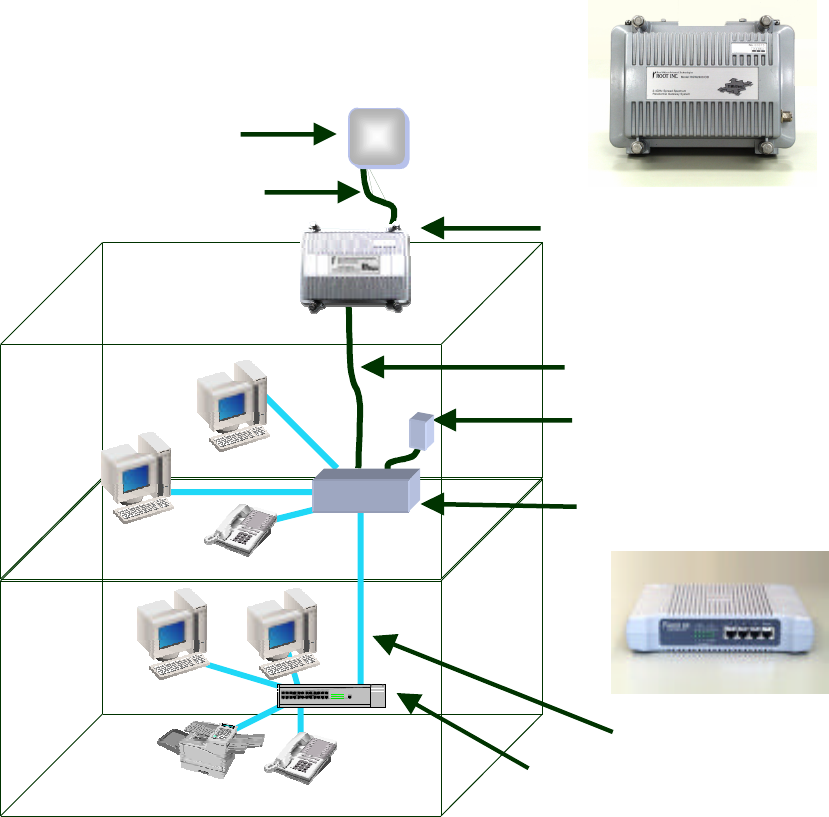
1 System Configurations
RGW2400/OD is a separate type radio router that can be installed outdoor.
It consists of the following components:
RGW2400/OD
OD main unit
Junction unit
(HUB with built-in 4 ports)
AC Adapter
IF cables (10m/20m)
Antennal cable
10/100BASE-T
HUB
Antenna
7
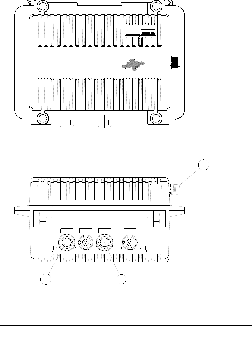
2 Name of Each Part
BLUE WHITE
11Mbit/sec
Model:RGW2400/OD
2.4GHzSpread Spectrum
ResidentiaiGateway System
RealObjectOrientedTechnologies
ROOT INC.
No. 00001
2.4DS4
1
2 3
RGW2400/OD_ Main Unit
(1)Antenna Terminal
Connect the antenna._After completion of connection, finish with self-melting
adhesive tape for waterproofing.
(2)Interface-Cable Connector 2
Connect the interface cable with a blue cap.
8
(3)Interface-Cable Connector 1
Connect the interface cable with a white cap.
Pass the interface cable. Connect the cable to the inside connector and then fit the cable
clamp. After completion of setting, finish with self-melting adhesive tape for
waterproofing.
FDX/Col
Main
Radio RunTxRxLink
RGW2400/OD
ROOT INC.
Main
Up3
2
1
Link/Act
1 2 3 Uplink
Link/Act 100
CONSOLE I/F 2 I/F 1 GND
BLUE WH ITE
DC IN
14 15
1716 18 19 20
4 5 6
7 8 9 10 11 12 13
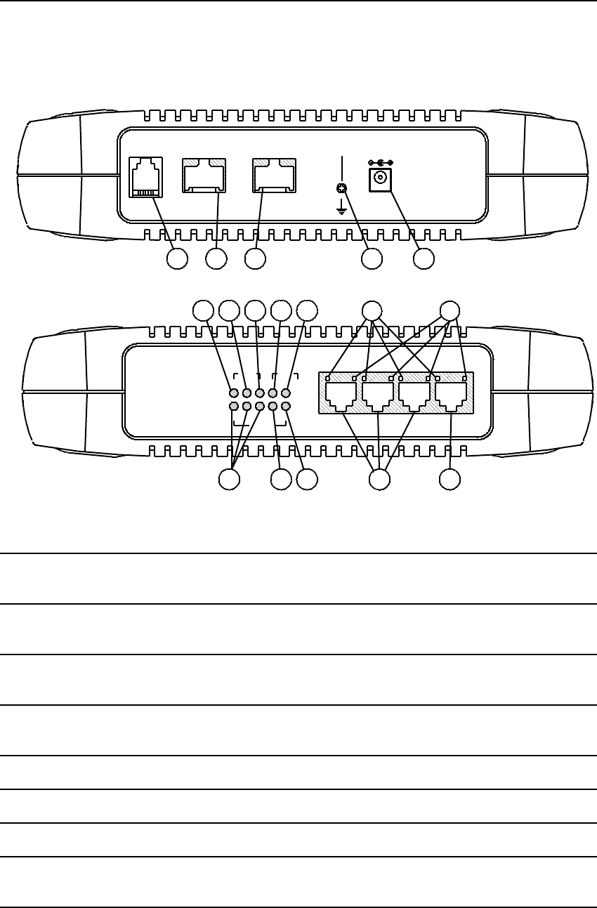
RGW2400/OD Junction Unit
(4)FDX/Col Lamp
Indicates the state of each port of the hub. It is on, while the main unit is connected by
full duplex. It blinks when a collision occurs.
(5)Uplink Port FDX/Col Lamp
It is the FDX/Col lamp of Uplink port of the hub and has the same contents of display
as other ports.
(6)Main Unit FDX/Col Lamp
It is the FDW/Col lamp between the main unit and hub and has the same contents of
other ports.
(7)Radio LINK Lamp
When a radio packet is received, this lamp turns on. When radio-related setting is
changed, it turns off.
(8)Radio RX Lamp
While receiving a radio packet, this lamp is on.
(9)Radio TX Lamp
While transmitting a radio packet, this lamp is on.
(10)RUN Lamp
When this unit is turned on and initializing is completed, this lamp is on.
(11)Main Unit Link/Act Lamp
When a link is established between the main unit and hub, this lamp is on.
This lamp also functions as Active indicator.
(12)Link/Active Lamp of Each Port

9
It is Link/Act lamp of each port of the hub.
(13)10/100 Lamp
When each port of the hub is connected with 10BASE-T, this lamp is off.
When it is connected with 100BASE-T, this lamp is on.
(14)10/100BASE-T Port
They are ports of the hub. Connect to PC(s) with straight cable(s).
(15)Uplink Port
It is a port provided only for Uplink. Connect it to other hub with a straight cable
(16)Console Connector for Maintenance
It is a serial port for maintenance such as settings etc. Connect it to a PC with an
exclusive cable.
(17)Interface Cable Connector 2
Connect the interface cable with a blue cap.
(18)Interface Cable Connector 1
Connect the interface cable with a white cap.
(19)GND Terminal
It is the GND terminal. Earth this terminal.
(20)DC Jack
Connect the attached DC adapter.
3 Installing Main Unit
3.1 Mount the Main Unit
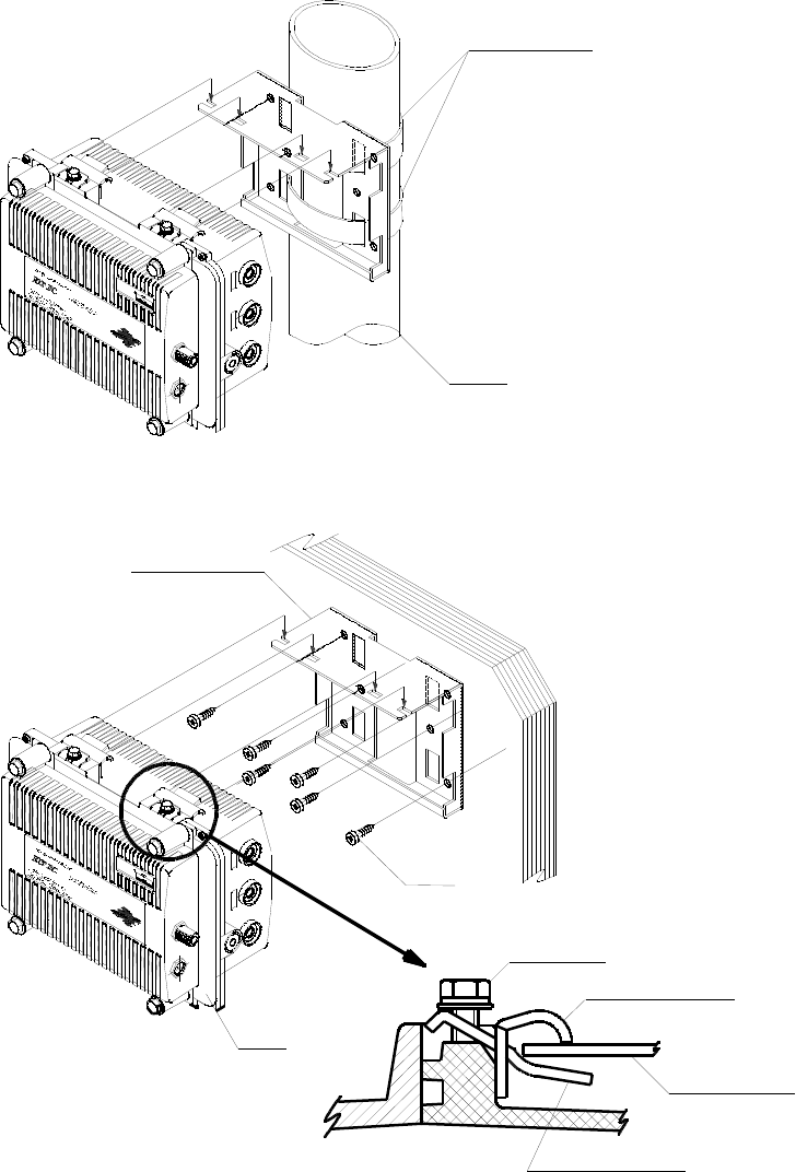
StainlessSteelBand
(OptionalParts)
Hexagonhead bolt
Main unit
Pole
Pole Mounting
Wall Mounting
ClampA
ClampB
The sectionalplan
Unit Holder
11
Mbit
/sec
M
od
el
:R
GW2 4
00
/O
D
2.4
GH
zS
pr
eadS
pect
rum
R
e
sid
en
tiaiGa
t
ewa
yS
y
st
em
Rea
lObje
ctOrientedTe
ch
n
ol
o
gies
R
O
OTI
N
C
.
No.00001
2.4DS4
Unit Holder
Tappingscrew
11
Mbit
/sec
M
od
el
:R
GW
24
00
/O
D
2.4GH
zS
pr
eadS
pect
rum
R
e
sid
en
tiaiGa
t
ewa
yS
y
st
em
R
ea
lObje
ctOrie
ntedTe
ch
n
ol
o
gies
R
O
OTI
N
C
.
No
.00001
2
.4DS4
3.2 Installing the Interface Cable
1. Slide the plug cover of each interface cable for few inches.
*1: Only Main Unit side can slide the cover.
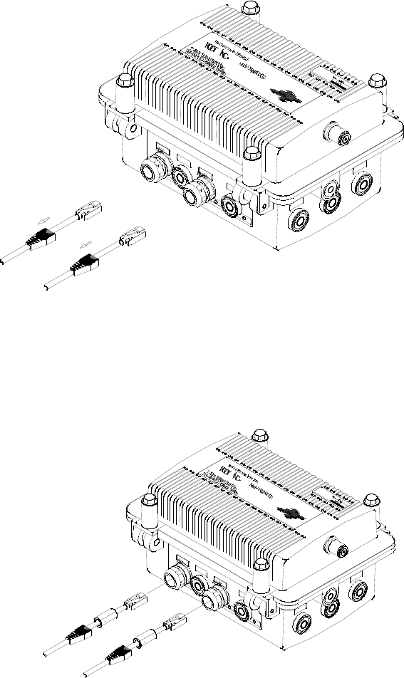
11
2. Loosen the plastic shells of bushings for interface cables.
*2: To ease insertion of the cables.
W
H
ITE
BL
UE
1
1M
b
it
/sec
M
o
del:R
G
W
2
4
00
/O
D
2
.4G
HzS
p
rea
dS
pectru
m
R
eside
ntiaiGa
tew
a
yS
yste
m
R
ealOb
je
c
tO
rien
tedTechn
o
lo
gies
R
O
O
TIN
C
.
N
o.0
0
00
1
2
.4
DS4
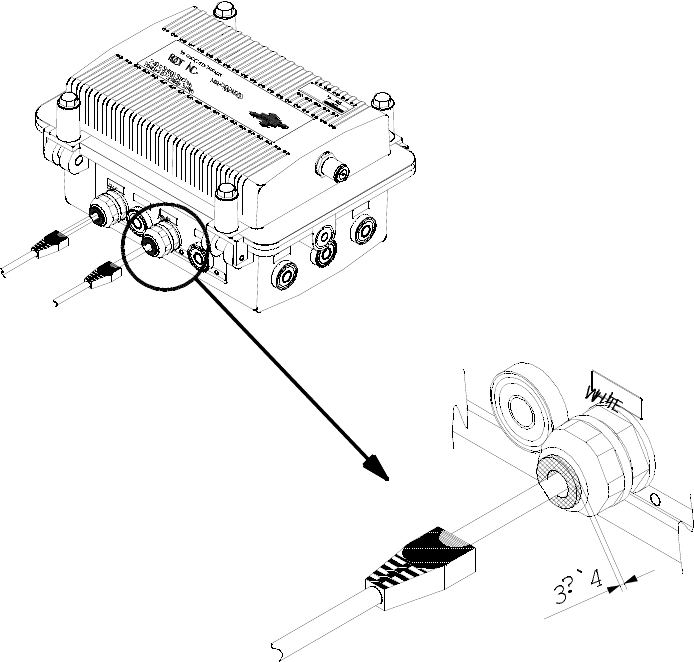
3. Prepare rubber gaskets and put them on each cable.
*3: Just behind of the plug.
4. Insert the cables and gaskets into the bushings one by one.
*4: Be sure, Blue (blue plug cover) cable to “BLUE” labeled bushing,
and White (transparent plug cover) cable to “WHITE” bushing .
W
H
ITE
BL
UE
1
1
Mb
it
/sec
M
o
del:R
G
W
2
4
0
0
/O
D
2
.4G
HzS
p
rea
dS
pec
tru
m
R
eside
ntia
iGa
tew
a
yS
yste
m
R
ea
lO
b
jec
tO
rien
te
dTech
n
olo
gies
R
O
O
TIN
C
.
N
o.0
0
00
1
2
.4DS4
5. Confirm if the plugs are engaged to the sockets in the box.
*5: When the plug is locked, a click sound occurs.
Pay attention on the rotation of the cable: to set the lock lever upward.
6. Tighten the plastic shells of the bushings.
*6: Up to end of the traverse.
12
(mm)
3?`4
W
H
ITE
W
H
ITE
BL
UE
1
1Mb
it
/sec
M
o
del:R
G
W
2
4
0
0
/O
D
2
.4G
HzS
p
rea
dS
pec
tru
m
R
e
side
ntia
iGa
tew
a
yS
yste
m
R
ealO
b
jec
tO
rien
tedTechn
o
lo
gies
R
O
O
TIN
C.
No
.0
00
0
1
2
.4
DS4
13
4 Antenna Selection
NOTICE
The antennas for the RGW2400/OD must be professionally installed on permanent structures for
outdoor operations. The installer is responsible for ensuring that the limits imposed by the Federal
Communications Commission (FCC) Regulations with regard to Maximum Effective Isotropic
Radiated Power (EIRP) and Maximum Permissible Exposure (MPE) are not violated. As such,
installer must insure that a separation of at least 2m is maintained at all times between the transmit
antenna and all persons.
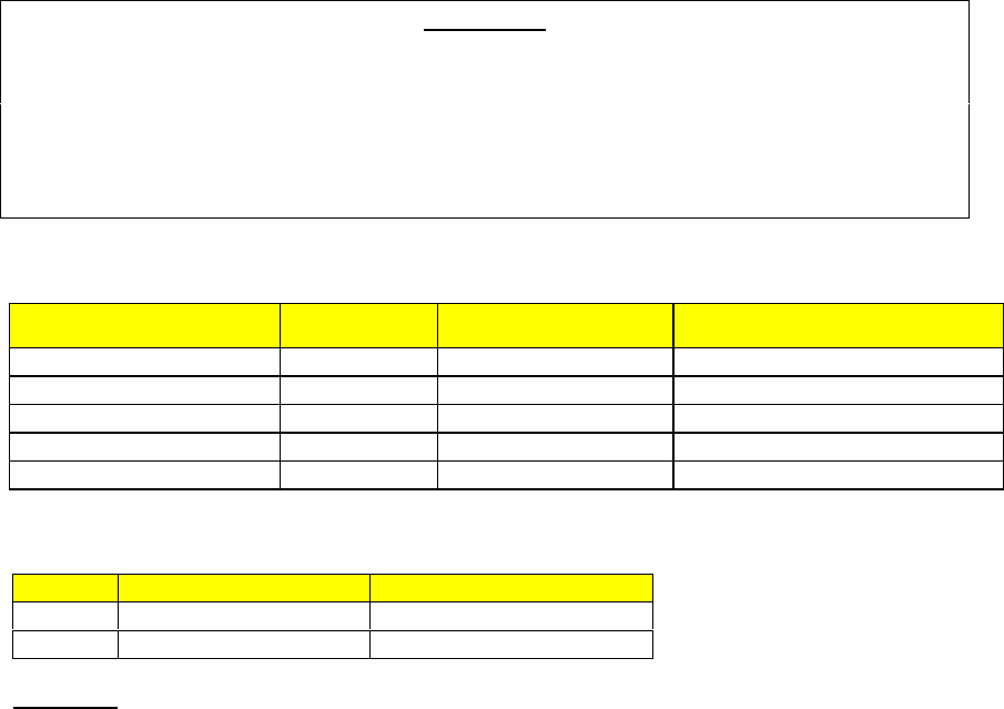
4.3 Antenna List
Antenna type Gain (dBi) Model ID Operating Channels, US
Omni 6 MFB24006 5,6,7 (with 45 ft cable min.)
Patch 8 MP24008XFPT 5,6,7 (with 45 ft cable min.)
Omni 10 MFB24010 5,6,7 (with 45 ft cable min.)
Sector 13 MSP24013MB 5,6,7,8,9 (with 45 ft cable min.)
Directional 15 HG2415G 5, 6 (with 45 ft. cable min.)
4.4 Cable List
NO. Length(ft.) Loss(dB)
1 15 1.02
2 40 2.72
NOTICE
It is possible only to connect it with Point to Point when the value by which the cable
loss is pulled from the antenna gain is 14dBi or more. Do not use it in Point to
multipoint.

14
5 Specifications
General
Characteristics Specifications
Power supply Single phase AC120V 60Hz
Power consumption 8W 12VA
Power feed AC adaptor
Main unit: 270_198_134mmDimensions
Junction unit: 220_209_50mm
Main unit: 4.4kgWeight
Junction unit: 0.7kg
LED Indicators Run, Link/Act
Switching Hub
Characteristics Specifications
Conforming to IEEE802.3 10BASE-TStandard
and IEEE802.3u_100BASE-TX
Number of ports 4 (One port for Uplink only)
At full duplex: 802.3x flow control methodFlow control
At half duplex: Back pressure method
MAC address table 1024
Aging time 5 minutes
Frame buffer 128Kbytes
Switching system Store-and-forward
LED Indicators Link/Act, 10/100, FDX/Col (for Port 1 to 3,
Uplink and Main)
Radio Interface
Characteristics Specifications
Standard FCC
Frequency in use 2400 to 2483.5MHz
Antenna connector N-J type
Modulation system DSSS
Transmission power 10mW/MHz (Max.)
Frequency channel 2412 to 2472MHz (13 ch)
Transmission rate 1,2,5.5,11Mbps
MAC protocol IEEE802.11b
LED Indicators TX, RX, Link
15
6 For More Help
Contact:
ROOT INC.
1-17-8, NISHIKATA BUNKYO-KU
TOKYO 113-0024, JAPAN
E-Mail: sales@root-hq.com