Roseman Engineering 2288 Hardwire FIA User Manual
Roseman Engineering Ltd. Hardwire FIA
User Manual

FuelFocus™ FMS System
Installation Guide
#RID-FG3-04-AW
Version 1.7 December 2016
AssetWorks LLC
998 Old Eagle School Road, Suite 1215
Wayne, PA 19087
Telephone: 610.225.8350
Facsimile: 610.971.9447
www.assetworks.com
Copyright © 2016 AssetWorks LLC
All Rights Reserved.

998 Old Eagle School Road, Suite 1215 | Wayne, Pennsylvania 19087 | T: 610-225-8350 | F: 610.971.9447 | www.assetworks.com
2
Table of Contents
1 Introduction .............................................................................................................................. 5
Purpose .............................................................................................................................. 5
System Overview ................................................................................................................ 5
Components Overview ........................................................................................................ 5
1.3.1 Modular Fleet Journal (FJ3) ......................................................................................... 6
Required Tools ................................................................................................................... 7
Required Materials .............................................................................................................. 7
Wiring Instructions .............................................................................................................. 7
2 Installation ................................................................................................................................ 8
Installation Considerations .................................................................................................. 8
3 FJ3 Installation ....................................................................................................................... 10
Mount the FJ3 ................................................................................................................... 10
Mount the RF Antenna ...................................................................................................... 12
Connect the FJ3 to the Battery or Power Source .............................................................. 12
Connect the FJ3 to Ground ............................................................................................... 12
4 Wiring VSS or Pulse Vehicles ................................................................................................ 13
Locating the Vehicle Speed Sensor (VSS) ........................................................................ 13
Connect the Data Interface to the FJ3............................................................................... 13
4.2.1 Connect the FJ3 an Odometer ................................................................................... 27
4.2.2 Electronic Odometer or Speedometer ........................................................................ 27
4.2.3 Reed Type Mechanical Adaptor ................................................................................. 27
4.2.4 Engine Hours ............................................................................................................. 28
5 Wiring the CAN Bus Vehicles ................................................................................................. 30
Connect the Ignition Switch to the FJ3 .............................................................................. 30
Connect the Data Interface to the FJ3............................................................................... 30
5.2.1 Connect the FJ3 to an OBD II Connector (Light Duty Vehicle) ................................... 44
5.2.2 Connect the FJ3 to a J1939 Connector (Heavy Duty Vehicle) .................................... 45
5.2.3 Connect the FJ3 to a 3 pin J1939 Connector (Heavy Duty Vehicle) ........................... 47
6 Wiring J1708 Vehicles............................................................................................................ 48
Connect the Ignition Switch to the FJ3 .............................................................................. 48
Connect the Data Interface to the FJ3............................................................................... 48
6.2.1 Connect the FJ3 to the J1708 CAB9 Connector ......................................................... 62
6.2.2 Connect the FJ3 to the J1708 CAB Connector ........................................................... 64
7 Completion of Installation ....................................................................................................... 65
Verify Installation .............................................................................................................. 65
8 FJ3 Flashing Tool .................................................................................................................. 66
Purpose ............................................................................................................................ 66
Preparation steps .............................................................................................................. 66
Updating the FJ3 Flash Tool Version ................................................................................ 67
Instructions for Flash Tool FJ3 Box V1 .............................................................................. 71
Instructions for Flash Tool FJ3 Box V4 and Above ............................................................ 72
9 Fueling Options ...................................................................................................................... 73
SVID Mounting and Installation ......................................................................................... 73
9.1.1 Mounting the Fuel Inlet Antenna (FIA) ....................................................................... 73
9.1.2 Mounting the SVID ..................................................................................................... 74
9.1.3 FIA to SVID ................................................................................................................ 74
9.1.4 SVID Installation ........................................................................................................ 75
Hardwire Fuel Inlet Antenna Connector Installation Instructions ....................................... 79

998 Old Eagle School Road, Suite 1215 | Wayne, Pennsylvania 19087 | T: 610-225-8350 | F: 610.971.9447 | www.assetworks.com
3
9.2.1 Troubleshooting ......................................................................................................... 81
10 Connecting the FJ3 to the GPS Tracking Device [Optional] ................................................... 82
11 Driver ID [Optional] ................................................................................................................ 84
Connecting the Driver ID ................................................................................................... 84
Installing the Driver ID Reader [Tag Reader] ..................................................................... 85
12 Appendices ............................................................................................................................ 87
Appendix A: Capturing Vehicle Data ................................................................................. 87
12.1.1 Capturing Odometer and Engine Hours Information................................................... 87
12.1.2 Vehicle Data Collection (VDC) - Option...................................................................... 87
12.1.3 Vehicle Speed Sensor (VSS) ..................................................................................... 87
Appendix B: CAN Bus Data Connectors .......................................................................... 90
12.2.1 Vehicle OBD-II Connector J1962 ............................................................................... 90
12.2.2 SAE J1939 Data Interface Connector ........................................................................ 91
12.2.3 3 PIN J1939 Data Interface Connector....................................................................... 91
Appendix C: J1708 Data Connectors ................................................................................ 92
12.3.1 SAE J1708 Data Interface Cables .............................................................................. 92
Option 1: SAE J1708 Model 1708CAB9 ................................................................................... 92
Option 2: SAE J1708 Model 1708CAB ..................................................................................... 92
Appendix D: Wiring for Speed Pulse ................................................................................. 93
12.4.1 Speed Pulse Wiring ................................................................................................... 93
12.4.2 Speed Pulse Wiring with Passive GPS ...................................................................... 94
12.4.3 Speed Pulse Wiring with Passive GPS and Driver ID ................................................. 95
Appendix E: CAN Bus Wiring for Light Duty Vehicles ........................................................ 96
12.5.1 CAN Bus: Light Duty Vehicles .................................................................................... 96
12.5.2 CAN Bus: Light Duty with Passive GPS ..................................................................... 97
12.5.3 CAN Bus: Light Duty with Passive GPS and Driver ID ............................................... 98
Appendix F: CAN Bus Wiring for Heavy Duty Vehicles ..................................................... 99
12.6.1 CAN Bus: Heavy Duty Vehicles ................................................................................. 99
12.6.2 CAN Bus: Heavy Weight with Passive GPS ............................................................. 101
12.6.3 CAN Bus: Heavy Weight with Passive GPS and Driver ID ....................................... 103
Appendix G: J1708CAB [6-pin] Connector Wiring ........................................................... 105
12.7.1 Wiring for the J1708CAB [6-pin] Connector ............................................................. 105
12.7.2 Wiring for the J1708CAB [6-pin] Connector with Passive GPS ................................ 106
12.7.3 Wiring for the J1708CAB [6-pin] Connector with Passive GPS and Driver ID ........... 107
Appendix H: The FCC Wants You to Know .................................................................... 108

998 Old Eagle School Road, Suite 1215 | Wayne, Pennsylvania 19087 | T: 610-225-8350 | F: 610.971.9447 | www.assetworks.com
4
Important Notice
AssetWorks LLC cannot guarantee the RF Vehicle ID Box installation techniques
discussed herein are complete and effective on every make, model and year of vehicle
and equipment now in the marketplace or coming in the future. At times vehicle
manufacturers make changes to the engine computer, wiring and/or electronics with new
model years and in fact also during mid-year production. After market accessories may
also impact the installation of the RF Vehicle ID Box. AssetWorks provides updates as
soon possible after discovering installation challenges, new OBD types or anything
effecting proper operation. We request feedback from the many very knowledgeable
Automotive Technicians working with this technology. If installation issues arise with new
model years or unique equipment we request immediate and detailed feedback so
corrections and enhancement may be made in a timely fashion. Working together we can
assure that the FuelFocus system remains the finest available. Information on updates and
new programs or procedures will be made available via the Fuel Focus installation
trainers, the newsletter and the customer support desk. AssetWorks urges all trained
Technicians , Supervisors and Managers to avail themselves of the newsletter by
contacting " AssetWorks Fuel Support" <fuelsupport@assetworks.com> to be included on
the
subscription list.

998 Old Eagle School Road, Suite 1215 | Wayne, Pennsylvania 19087 | T: 610-225-8350 | F: 610.971.9447 | www.assetworks.com
5
1 Introduction
Purpose
This FuelFocus® Vehicle Subsystem Installation Manual instructs how to install the
Modular Fleet Journal Type 3 (FJ3). Review this manual prior to installing the FJ3.
Incorrect installations may cause the system to malfunction.
Read this entire manual before your first installation.
System Overview
The AssetWorks FJ3 is the integral component of the AssetWorks FuelFocus® FMS
System in the vehicle. The following are required to properly install and utilize the
FuelFocus® FJ3:
• AssetWorks FuelFocus® Fuel Management System Island Controllers
• Pumps/dispensers modified using FuelFocus nozzle tags
• WAF Receiver Kit installed in the FuelFocus Island Controller
A shielded cable is required, as described in the manual. Failure
to use one will void the warranty.
Components Overview
This section describes the various components that compose the AssetWorks
FuelFocus® System, for you to determine the equipment needed for your particular
fleet of vehicles.
Each Vehicle Unit includes the following components:
• SVID (Small Vehicle Identification Device) Type 3 (If applicable)
• Modular Fleet Journal Type 3 (FJ3)
• Fuel Inlet Antenna (FIA)
• FIA Adapter (if SVID is not used)

998 Old Eagle School Road, Suite 1215 | Wayne, Pennsylvania 19087 | T: 610-225-8350 | F: 610.971.9447 | www.assetworks.com
6
1.3.1 Modular Fleet Journal (FJ3)
The FJ3 is the main component of the Fleet Journal system installed in the vehicle. It
stores the vehicle usage data, which includes the start and end times of a trip,
beginning and ending odometer readings, maximum speed and more. This provides
the fleet manager full supervision and control over the use of all fleet vehicles.
The FJ3 data automatically transfers to the Fleet Journal application via the WAF
unit. Fleet Journal processes the data and generates the required reports for the fleet
manager to use.
The FJ3 can be configured to record odometer and/or engine hour readings
The Vehicle data is uploaded in one of the following methods:
• 2.4GHz Wireless connection with fuel station controller.
• 2.4GHz Wireless VDC connection at parking lot, garage, etc.
• On line connection via cellular modem.
This document describes the installation procedures for the FJ3 (2.4 GHz).
Description Part No.
Modular Fleet Journal Type 3 RID-FG3-04-AW
Power Consumption
The FJ3 receives its power from the vehicle’s battery. The power requirements are:
Measure values
Average @ 12V
Engine ON 27mA 34mA with hardwire FIA
Sleep 7mA 12mA with hardwire FIA
Note
If you experience battery drain, we recommend the use of an automotive
“shut-down” timer or similar, available from the automotive aftermarket. This
is commonly used on police/emergency and utility vehicles to prevent dead
batteries due to drain from aftermarket installed electronics.

998 Old Eagle School Road, Suite 1215 | Wayne, Pennsylvania 19087 | T: 610-225-8350 | F: 610.971.9447 | www.assetworks.com
7
Required Tools
The following tools are required to complete the installation procedures:
• Screwdrivers
• Box wrenches
• Crimping tool
• Wire stripping tool
• Drill with 1/8" drill bit
• Heat gun (for heat-shrink insulation)
Required Materials
The following materials are required to complete the installation procedures:
• Two conductor twisted pair cable – 20 - 22 AWG with foil shield and drain wire
• Wire terminals. Do not use Scotch Locks.
• 3/8" inch self-tapping, sheet metal screws (Rittal SZ2487 or equivalent) with
matching flat washers and split washers
• Grommets
• Three amp fuse and fuse holder
• Wire ties, wire solder and wire loom
• Heat shrink tubing
• Butt connectors for 20 - 22 AWG wire
Wiring Instructions
The general procedures for wiring the FJ3 are as follows:
• Using a wire stripping tool, remove insulation to bare 3/8" of wire.
• Press firmly on the connector locking tab.
• Insert the exposed wire end.
• Release the locking tab.
• Check to make certain the wire is held firmly in place and that the wire insulation
is not pinched in the terminal.
Use gasoline and oil-resistant wiring only. Route wires away
from moving parts and the vehicle’s exhaust system.

998 Old Eagle School Road, Suite 1215 | Wayne, Pennsylvania 19087 | T: 610-225-8350 | F: 610.971.9447 | www.assetworks.com
8
2 Installation
Follow the installation instructions detailed in the following sections.
Note
When performing wiring procedures, follow the instructions in Wiring
Instructions on page 7.
Installation Considerations
Before mounting the FJ3 and SVID, determine the best place to install. Consider the
following four basic recommendations:
• Weather Protection – Select a weather-protected location. The FJ3 is not
waterproof. Consider an area where it will not be exposed to water/moisture,
during vehicle operation or cleaning.
• Cable Runs – The Fuel Inlet Antenna (FIA) is mounted in a Class I, Division I
hazardous location. The wiring is intrinsically safe, and therefore must not come
within two inches of any existing wires or cable harness. Installing the FJ3 to
minimize the FIA cable length makes it easier to adhere to this safety rule. The
FJ3 also requires connections to power and ground, so it should be located in an
area where you can readily access these sources easily.
• Cable Routing –Keep cables from coming in contact with moving parts, and
away from parts that generate excessive heat, electrical noise, or areas that may
impede safety. These areas include the drive shaft, fan blades, belts, adjustable
steering column, alternators, fluorescent lighting, foot pedals, radiator, engine,
exhaust system, and other dangerous areas. Try to gather all conductors at a
common point when routing cables, routing the cables to the FJ3 in a group. The
FJ3 must be kept at least three feet from the filler neck opening. This includes
cases where the FJ3 is mounted in the trunk, as that is not a vapor-sealed area.
Wire loom is recommended to protect the wiring.
• Cable Clearance – Keep the FJ3 and cables at least six (6) inches from devices
with a strong magnetic field such as fan motors or speakers.
Do not use an electric drill or any other electrically-powered
tools within 3 feet of the filler neck or fuel tank, as this area is
considered a Class I, Group D hazardous location.
Do not use a heat gun or any other heating device within 3 feet
of the filler neck or fuel tank as this area is considered a Class
I, Group D hazardous location.
The Fuel Inlet Antenna and its wiring are intrinsically safe.
Ensure there is complete separation between the transmitter
wiring and any existing auto wiring. Also avoid routing wires
near the auto exhaust systems or fuel lines.
Mount the FJ3 at least 3 feet from the filler neck.
Water and/or moisture can seep in through the connectors
causing permanent damage!
998 Old Eagle School Road, Suite 1215 | Wayne, Pennsylvania 19087 | T: 610-225-8350 | F: 610.971.9447 | www.assetworks.com
9
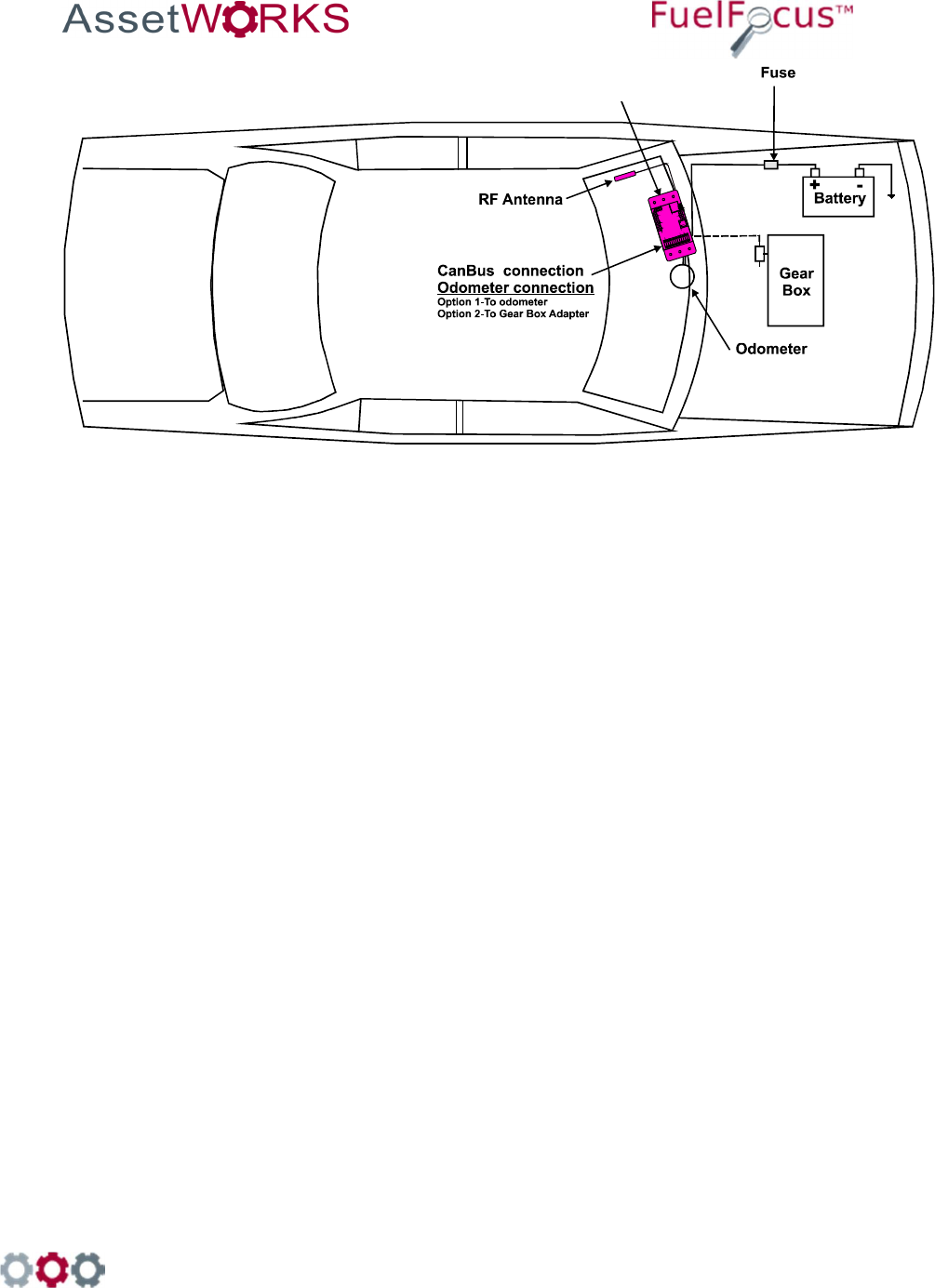
Figure 1: Typical Vehicle Wire Routing
FJ3

998 Old Eagle School Road, Suite 1215 | Wayne, Pennsylvania 19087 | T: 610-225-8350 | F: 610.971.9447 | www.assetworks.com
10
3 FJ3 Installation
Mount the FJ3
1. After reviewing the recommendations listed in 2.1 “ Installation Installation Considerations”,
mount the FJ3 as follows:
• If possible, mount it on the same side of the vehicle as the filler neck.
• For a passenger car, the FJ3 can be mounted under the dashboard or in the
trunk, provided that the unit is at least 3 feet from the filler neck.
• For a truck or bus, the FJ3 can be mounted inside the vehicle's electric
enclosure.
2. Drill at least two 1/8" holes for the FJ3 mounting. Use the FJ3 to mark the holes (see Figure 2:
FJ3 Wiring Diagram)
3.
4. Figure 2 shows the FJ3 mounted on the vehicle chassis, or any other metal portion of the vehicle
whenever possible.
Do not use an electric drill or any other electrical power tool
within 3 feet of the filler neck or fuel tank. This area is
considered a Class I Group D hazardous location.
5. Using the two 3/8" self-tapping mounting screws and two lock washers, mount the FJ3 to the
vehicle frame. You must use two self-tapping sheet metal screws.
998 Old Eagle School Road, Suite 1215 | Wayne, Pennsylvania 19087 | T: 610-225-8350 | F: 610.971.9447 | www.assetworks.com
11
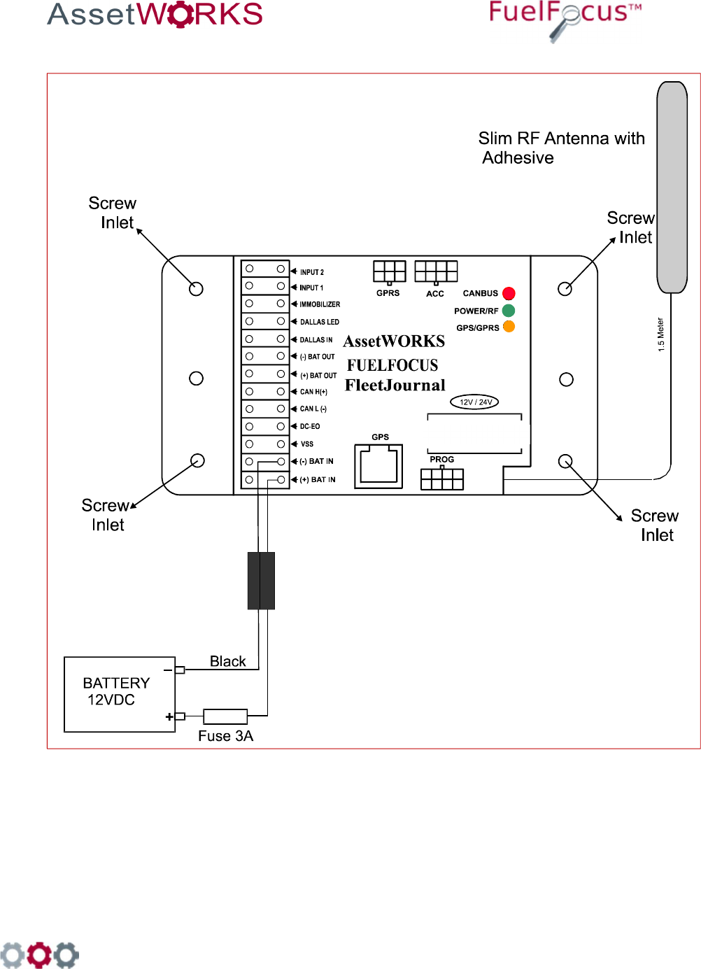
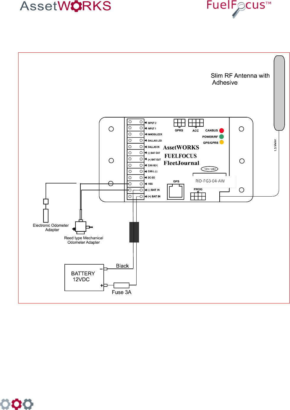
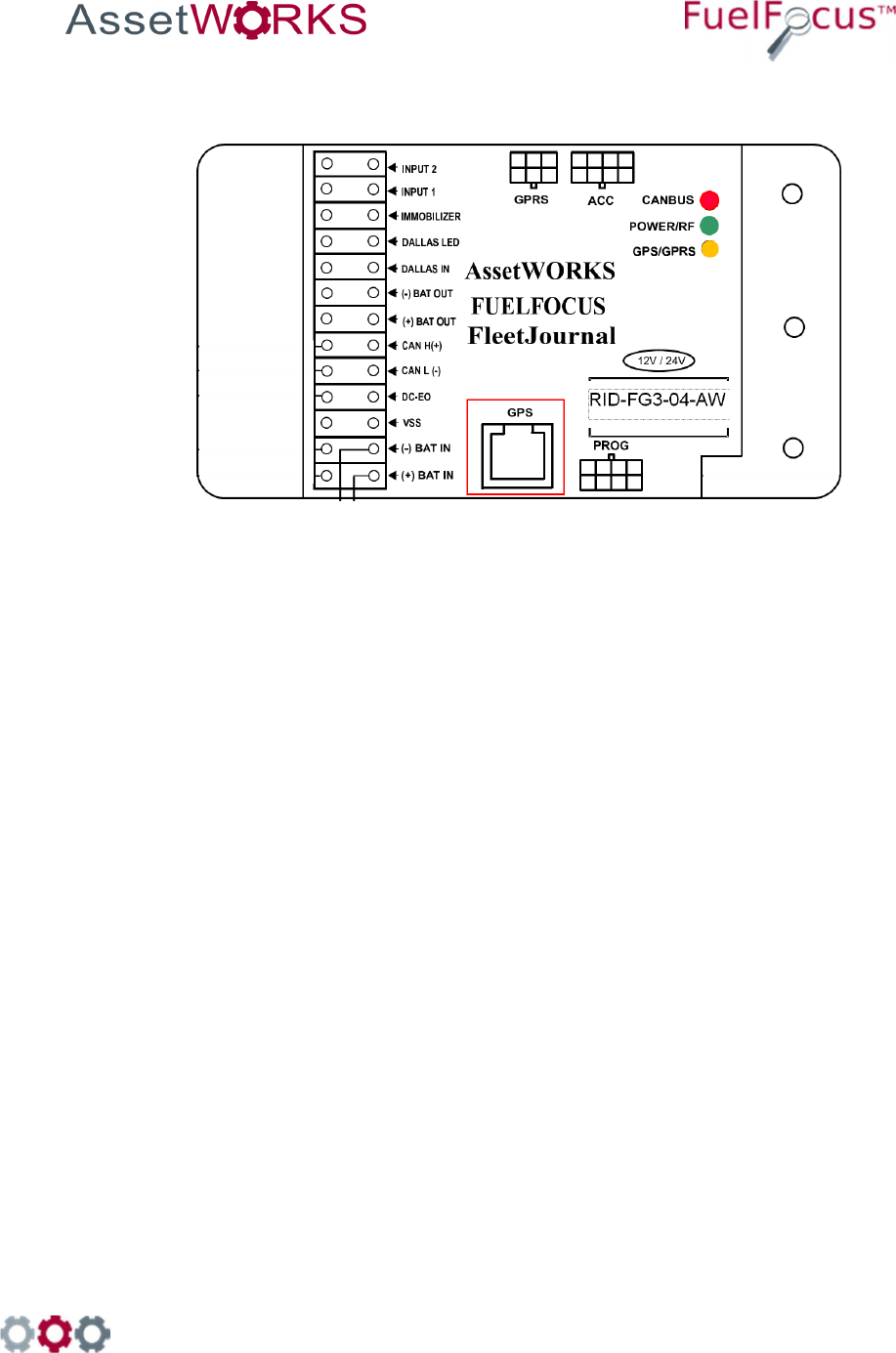
Figure 2: FJ3 Wiring Diagram
RID-FG3-04-AW

998 Old Eagle School Road, Suite 1215 | Wayne, Pennsylvania 19087 | T: 610-225-8350 | F: 610.971.9447 | www.assetworks.com
12
Mount the RF Antenna
The RF Antenna can be mounted by removing the protective layer from the adhesive
back and attaching to the vehicle windshield. The same location can be used near
the rear window if desired.
Note: Clean the windshield before mounting the antenna.
In busses, the RF Antenna can be mounted in the sign compartment area, if made of
fiberglass.
The antenna must not be concealed on all sides by metal.
Note
The RF Antenna should be fastened and secured appropriately. Do not coil
the antenna wire.
Connect the FJ3 to the Battery or Power Source
Positive (+) connection can be from any 12 or 24 DC volt source.
1. If your power source is the battery, run a wire from the battery to the FJ3 and
connect it to BATT (+). This wire requires a 3 amp fuse to protect the FJ3.
Connect the FJ3 to Ground
Connect the FJ3 to a ground, to the vehicle metal chassis, or to the negative (-) post
on the vehicle's battery.
• When connecting to the vehicle battery:
Prepare a black auto wire with a terminal on each end. Connect the black (-)
cable from BATT (-) on the FJ3 to the negative (-) terminal on the battery. Tie the
wire to the vehicle frame.
• When connecting to the vehicle metal chassis:
Connect a black ground cable from BATT (-) on the FJ3 to one of the FJ3’s
mounting screws. Loop the cable end around the screw between the screw head
and the FJ3 plate and tighten the screw.
Note
This will connect the FJ3 to ground only if the FJ3 is affixed to the metal
chassis of the car.

998 Old Eagle School Road, Suite 1215 | Wayne, Pennsylvania 19087 | T: 610-225-8350 | F: 610.971.9447 | www.assetworks.com
13
4 Wiring VSS or Pulse Vehicles
Locating the Vehicle Speed Sensor (VSS)
The VSS usually originates near the rear of the transmission case. From there it
usually travels to the engine control computer, speedometer and the cruise control
computer. Pick a location to tap the circuit near the engine control computer
interface, reducing risk of incorrect data due to ignition noise. Also, as with any
electronic accessory, a good ground connection is necessary. Improper grounding
could result in a ground loop condition, which may affect the accuracy of the unit.
Note AssetWorks can provide you with an aftermarket catalog for VSS+
wire, its color, and how many pulses per mile the vehicle has.
Connect the Data Interface to the FJ3
The instructions for this procedure depend on the type of vehicle
To view how to capture vehicle data, refer to the Fueling Options
Either SVID [Fuel Inlet Antenna Connector P/N RID-IN-54]
Or Hardwire [Fuel Intel Antenna Connector P/N RID-EM-02]
Both options also require a Fuel Intel Antenna [P/N RVC-XX –XX]
SVID Mounting and Installation
4.3.1 Mounting the Fuel Inlet Antenna (FIA)
Note
Use shielded cable type Olympic part # 2886 or equivalent, polypropylene
insulated, twisted pair, aluminum Mylar shield, 20 – 22 AWG stranded
tinned copper drain wire, chrome vinyl jacket. Temperature rating: -20ºC to
60ºC.
Connect the FIA coil before mounting, to avoid using the heat gun
near the fuel tank. Before making this connection, plan on where
you are going to mount the SVID. Then make sure you have
clearance to pass the SVID from the filler neck to the mounting
location.
If you do not have enough clearance, first position the FIA coil on
the vehicle. Then pull the wire out to a safe distance (at least three
feet from the fuel filler neck) to heat the shrink-wrap insulation.
Then pull the wire back for final mounting.
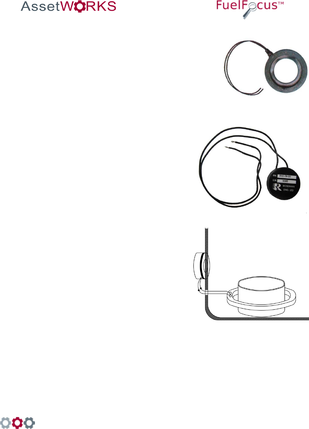
Select a Fuel Inlet Antenna (FIA) with an internal diameter that allows it to fit snugly over the

998 Old Eagle School Road, Suite 1215 | Wayne, Pennsylvania 19087 | T: 610-225-8350 | F: 610.971.9447 | www.assetworks.com
14
filler neck. (A variety of sizes are available from AssetWorks.) Slide the FIA down over the filler
neck and slide it back until it is securely in place. (See note)
The intrinsically safe FIA wires must be tie wrapped at various locations between the FIA and
the SVID. One tie will be placed on the FIA wire, directly behind the antenna, to prevent the
antenna from falling off the filler neck.
Note
The FIA must be placed no more than four inches from the filler neck
opening. If the exposed portion of the filler neck pipe is longer than four
inches, place a plastic tie behind the antenna to hold it in place. You may
now install the odometer adaptor (if required) according to the
manufacturer's instructions. Then proceed to "Mounting the SVID".
4.3.2 Mounting the SVID
The location of the SVID will be determined according to the device type.
SVID with external antenna is mounted in the vehicle trunk or behind the fuel tank.
Important
The SVID should be mounted on the vehicle before performing the
activation.
4.3.3 FIA to SVID
Connect each of the intrinsically safe FIA wires to the "T-Ring" points (Polarity is not important)
at the SVID. Pass the SVID and its intrinsically safe cable to the selected mounting site. You
must find a clear path to run the cable from the fuel tank to the selected SVID mounting site.
You may use existing holes in the vehicle body. Make sure not to drill outer parts of the vehicle
and not to cause any damage to the operation of vehicle. Use grommets to protect cable that
you pass through holes. Remove plastic or rubber parts blocking the way. Make sure to re-
install all removed parts after the wires have been passed through.
Do not use an electric drill or any other electrical power tools within
3 feet of the filler neck or fuel tank as this area is considered a
Class I, Group D hazardous location.

998 Old Eagle School Road, Suite 1215 | Wayne, Pennsylvania 19087 | T: 610-225-8350 | F: 610.971.9447 | www.assetworks.com
15
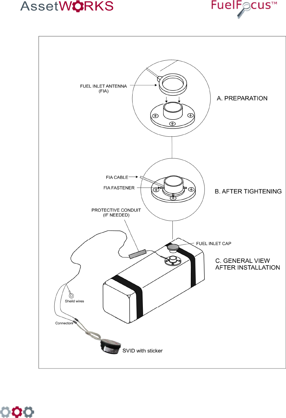
4.3.4 SVID Installation
4.3.4.1 SVID Installation with external antenna wires on fuel tank
1.
Install the Fuel Inlet Antenna
– FIA ring on the fuel tank
inlet. Select the FIA ring
according to the vehicle type.
2.
Route the FIA wires through a
protective conduit under
vehicle chassis to the SVID.
3.
Clean the surface of the
vehicle with alcohol; make
sure to remove all grease
and debris.
4.
Remove the sticker on the
back of the SVID device and
stick it to the cleaned surface
as shown.
5.
Connect the SVID antenna
wires with FIA wires using
two suitable connectors.

998 Old Eagle School Road, Suite 1215 | Wayne, Pennsylvania 19087 | T: 610-225-8350 | F: 610.971.9447 | www.assetworks.com
16
4.3.4.2
SVID Installation With External Antenna Wires on the Vehicle Trunk
1.
Install the fuel inlet antenna -FIA
ring on the fuel tank inlet. Select
a ring according to the vehicle
type.
2.
Drill 7mm hole in fueling
compartment, insert a grommet,
and insert the 2 wires. Install the
SVID in the vehicle trunk behind
the fuel inlet.
3.
Clean the surface of the vehicle
with alcohol. Make sure to
remove all grease and debris.
4.
Connect the SVID antenna wires
to the FIA ring wires with two
suitable connectors using
crimping tool.
998 Old Eagle School Road, Suite 1215 | Wayne, Pennsylvania 19087 | T: 610-225-8350 | F: 610.971.9447 | www.assetworks.com
17
4.3.4.3 FIA Installation on a Light Duty Vehicle Fuel Tank

998 Old Eagle School Road, Suite 1215 | Wayne, Pennsylvania 19087 | T: 610-225-8350 | F: 610.971.9447 | www.assetworks.com
18
4.3.4.4 Installation on a Heavy Duty Vehicle Fuel Tank
998 Old Eagle School Road, Suite 1215 | Wayne, Pennsylvania 19087 | T: 610-225-8350 | F: 610.971.9447 | www.assetworks.com
19
Hardwire Fuel Inlet Antenna Connector
Installation Instructions
FCC Compliance
FCC ID: 2AKAM2288
998 Old Eagle School Road, Suite 1215 | Wayne, Pennsylvania 19087 | T: 610-225-8350 | F: 610.971.9447 | www.assetworks.com
20
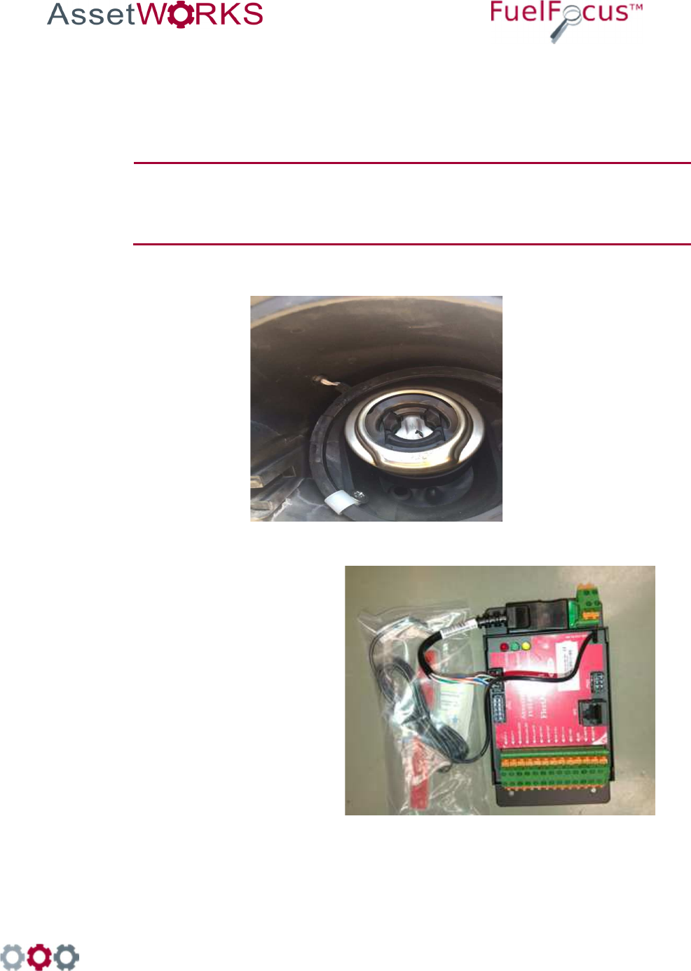
To install the Hardwire FIA:
1. Select a fuel inlet antenna diameter to fit the vehicle’s fuel tank inlet [one size larger].
2. Install it using the dedicated snaps provided.
3. Make sure the fuel inlet antenna cable is long enough to reach the location where the
FleetJournal 3 will be installed.
Note
If necessary the cable may be extended. Use shielded cable type Olympic
part # 2886 or equivalent, polypropylene insulated, twisted pair, aluminum
Mylar shield, 20 – 22 AWG stranded tinned copper drain wire, chrome vinyl
jacket. Temperature rating: -20ºC to 60ºC.
4. Solder and/or use moisture. To prevent connection problems in the future, proof the
connections and if necessary shrink the tubing.
5. Install the FleetJournal 3. See Chapter 3 FJ3 Installation.
6. Connect the hardwire FIA
connector to the FleetJournal 3
[FJ3] ACC connector.
7. Install the hardwire FIA on the FJ3
wall utilizing the magnetic base.
8. Plug the fuel inlet antenna wires
into the green connection points
next to each other.

998 Old Eagle School Road, Suite 1215 | Wayne, Pennsylvania 19087 | T: 610-225-8350 | F: 610.971.9447 | www.assetworks.com
21
4.4.1 Troubleshooting
If the Hardwire FIA connection does not work [no proper signal], do the following:
1. Ensure that you are using a correct FIA and have a signal of at least 10 cm. If not replace the
FIA.
2. If there is still no proper signal, replace the FIA wire connection.
Note
The Fuel Inlet Antenna Connector is a sealed unit and cannot be repaired in
the field. Please return the defective units. Download an RMA from the
AssetWorks PartWorks website.

998 Old Eagle School Road, Suite 1215 | Wayne, Pennsylvania 19087 | T: 610-225-8350 | F: 610.971.9447 | www.assetworks.com
22
5 Connecting the FJ3 to the GPS
Tracking Device [Optional]
The GPS device tracks the location of vehicles in the field.
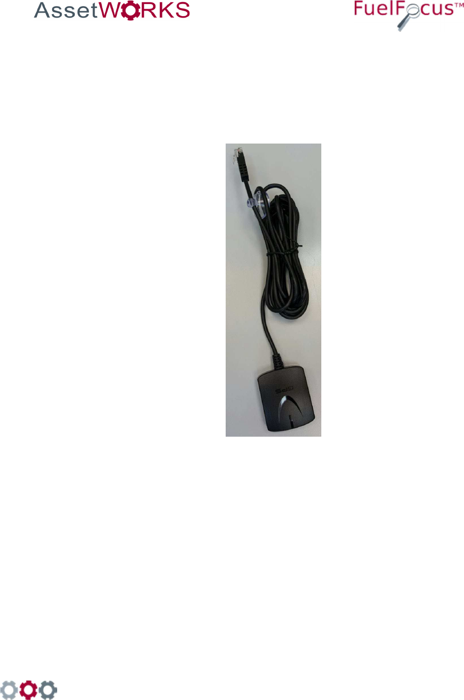
Figure 12 GPS Antenna Cable

998 Old Eagle School Road, Suite 1215 | Wayne, Pennsylvania 19087 | T: 610-225-8350 | F: 610.971.9447 | www.assetworks.com
23
To install the GPS tracking device:
1. Attach the RJ45 cable to the to the GPS connector on the FJ3.
2. Place the GPS antenna on the vehicle’s dashboard near the windshield.

998 Old Eagle School Road, Suite 1215 | Wayne, Pennsylvania 19087 | T: 610-225-8350 | F: 610.971.9447 | www.assetworks.com
24
6 Driver ID [Optional]
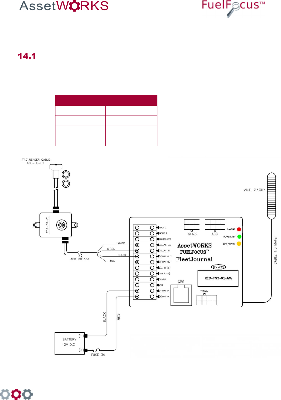
Connecting the Driver ID
To identify the driver of the vehicle, connect the Tag Reader wires to the FJ3 as
follows:
Wire Color Connect to:
White Dallas LED
Green Dallas In
Black (-) Bat Out
Red (+) Bat In
See Figure 13
Figure 13: Connecting the Driver ID reader to the FJ3

998 Old Eagle School Road, Suite 1215 | Wayne, Pennsylvania 19087 | T: 610-225-8350 | F: 610.971.9447 | www.assetworks.com
25
Installing the Driver ID Reader [Tag Reader]
Note: Place the Tag reader on the dashboard so that the Dallas key can be easily read.
1. Wire the Tag Reader cables to the FJ3 – see section Error! Reference source not found.
Error! Reference source not found..
2. Make a ½” hole on the dashboard for the Tag Reader.
3. Pull the Tag Reader through the hole.
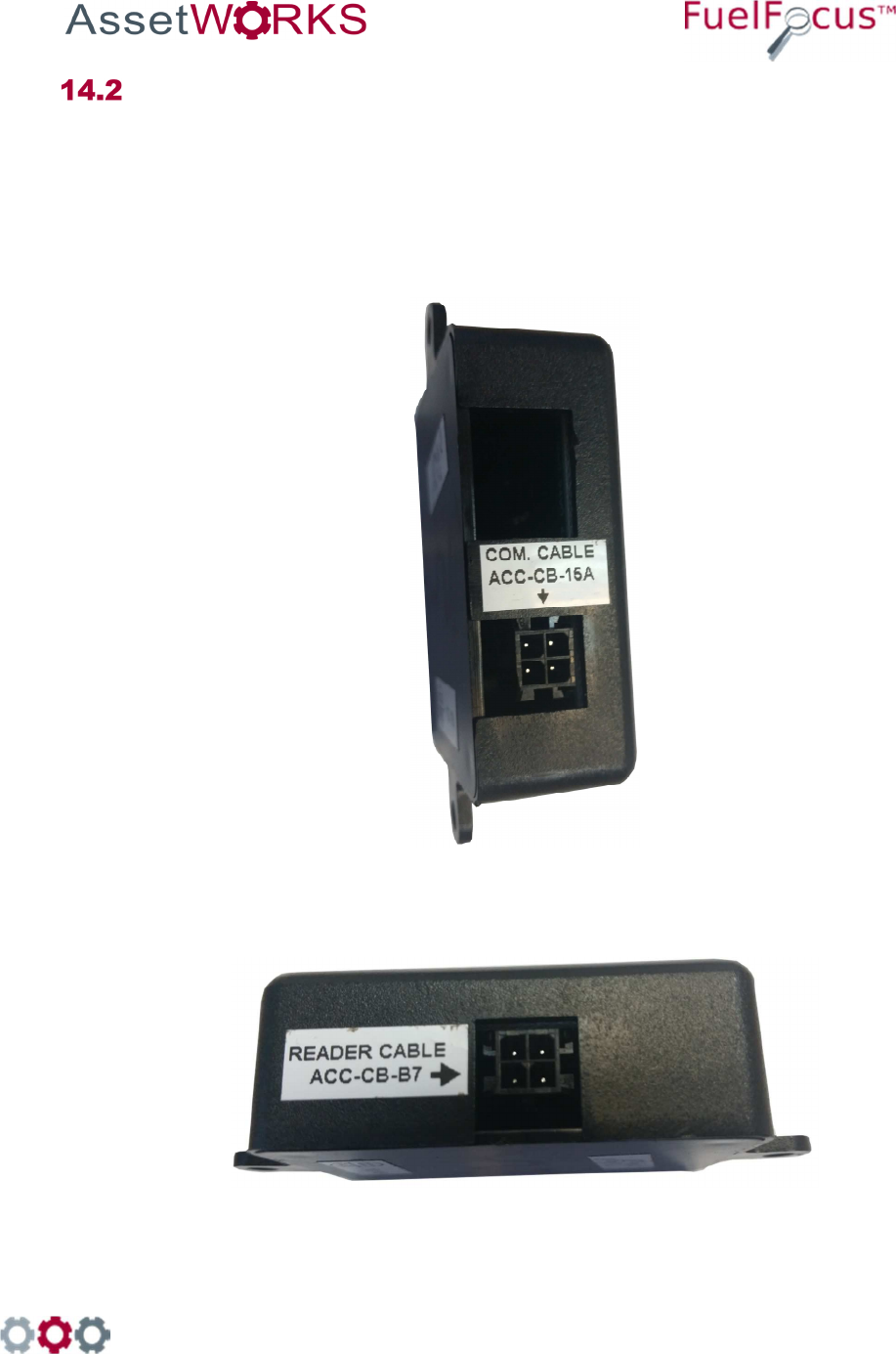
4. Connect the Com. Cable ACC-CB-15A cable to the FJ3.
Figure 14 COM Cable ACC-CB-15A
5. Connect the Reader Cable ACC-CB-B7 to the Driver ID Reader.
Figure 15 Reader Cable ACC-CB-B7

998 Old Eagle School Road, Suite 1215 | Wayne, Pennsylvania 19087 | T: 610-225-8350 | F: 610.971.9447 | www.assetworks.com
26
Important: The Driver ID Reader should be bright red after connecting and installing it correctly. If
there is a faint green light in the center of the Reader, this indicates that the Reader is
not correctly installed. All the connectors should slide in smoothly, do not force them.

998 Old Eagle School Road, Suite 1215 | Wayne, Pennsylvania 19087 | T: 610-225-8350 | F: 610.971.9447 | www.assetworks.com
27
7 Appendices
Appendix A: Capturing Vehicle Data
7.1.1 Connect the FJ3 an Odometer
There are two possible odometer connections:
Direct from either an electronic odometer or a speedometer.
From a mechanical odometer via a Reed type odometer adaptor. Also known as a
pulse transducer or “taxi tap”
Note If you are recording the vehicle's engine hours, you may skip this
section and go on to section 7.1.4 Engine Hours.
7.1.2 Electronic Odometer or Speedometer
If the vehicle has electronic instrumentation, run a single wire from the vehicle speed
sensor output VSS+ signal to the FJ3 and connect it to "VSS".
7.1.3 Reed Type Mechanical Adaptor
If the vehicle has a mechanical odometer, and using a Reed type adaptor, run two
wires to the FJ3 and connect it to "BATT(+)" and "VSS".
998 Old Eagle School Road, Suite 1215 | Wayne, Pennsylvania 19087 | T: 610-225-8350 | F: 610.971.9447 | www.assetworks.com
28
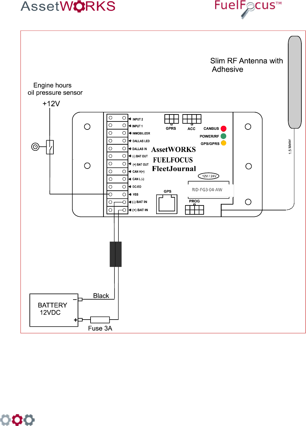
7.1.4 Engine Hours
To record engine hours, run a single wire from the oil pressure sensor (or any other
sensor that is at a continuous "high" state while the engine is running), to VSS.
Figure 3: FJ3 Wiring Diagram for Speed Pulse
998 Old Eagle School Road, Suite 1215 | Wayne, Pennsylvania 19087 | T: 610-225-8350 | F: 610.971.9447 | www.assetworks.com
29
Figure 4: FJ3 Wiring Diagram for Engine Hour Meter

998 Old Eagle School Road, Suite 1215 | Wayne, Pennsylvania 19087 | T: 610-225-8350 | F: 610.971.9447 | www.assetworks.com
30
8 Wiring the CAN Bus Vehicles
Connect the Ignition Switch to the FJ3
1. Run a wire from the vehicle ignition switch (or start/stop button on some hybrid
models) to the DC-EO terminal on the FJ3 (refer to Figure 5
: Wiring Diagram for
FJ3 with CAN Bus Interface for Light Duty Vehicles
and Figure 6: Wiring Diagram for
FJ3 with CAN Bus Interface for Heavy Duty Vehicles or Figure 7: Wiring Diagram
for FJ3 with CAN Bus Interface (3-pin connector) for Heavy Duty Vehicles)
2. The FJ3 needs constant 12 or 24 volt power at the BAT+ and BAT- terminals
Note
FJ3 will not function properly if an ignition On/Off wire is not
connected to the DC-EO terminal. FJ3 goes into Sleep mode
(Power Save) 30 minutes after turning off the ignition.
Connect the Data Interface to the FJ3
The instructions for this procedure depend on the type of vehicle, whether it is a heavy
duty vehicle or a light duty vehicle. Light duty vehicles have an OBD II connector, while
heavy duty vehicles have a SAE J1939 connector. The following sections provide
instructions for both types of vehicles.
To view the connectors’ pin out information, refer to Fueling Options
Either SVID [Fuel Inlet Antenna Connector P/N RID-IN-54]
Or Hardwire [Fuel Intel Antenna Connector P/N RID-EM-02]
Both options also require a Fuel Intel Antenna [P/N RVC-XX –XX]
SVID Mounting and Installation
8.3.1 Mounting the Fuel Inlet Antenna (FIA)
Note
Use shielded cable type Olympic part # 2886 or equivalent, polypropylene
insulated, twisted pair, aluminum Mylar shield, 20 – 22 AWG stranded
tinned copper drain wire, chrome vinyl jacket. Temperature rating: -20ºC to
60ºC.
Connect the FIA coil before mounting, to avoid using the heat gun
near the fuel tank. Before making this connection, plan on where
you are going to mount the SVID. Then make sure you have
clearance to pass the SVID from the filler neck to the mounting
location.
If you do not have enough clearance, first position the FIA coil on
the vehicle. Then pull the wire out to a safe distance (at least three
feet from the fuel filler neck) to heat the shrink-wrap insulation.
Then pull the wire back for final mounting.

998 Old Eagle School Road, Suite 1215 | Wayne, Pennsylvania 19087 | T: 610-225-8350 | F: 610.971.9447 | www.assetworks.com
31
Select a Fuel Inlet Antenna (FIA) with an internal diameter that allows it to fit snugly over the
filler neck. (A variety of sizes are available from AssetWorks.) Slide the FIA down over the filler
neck and slide it back until it is securely in place. (See note)
The intrinsically safe FIA wires must be tie wrapped at various locations between the FIA and
the SVID. One tie will be placed on the FIA wire, directly behind the antenna, to prevent the
antenna from falling off the filler neck.
Note
The FIA must be placed no more than four inches from the filler neck
opening. If the exposed portion of the filler neck pipe is longer than four
inches, place a plastic tie behind the antenna to hold it in place. You may
now install the odometer adaptor (if required) according to the
manufacturer's instructions. Then proceed to "Mounting the SVID".
8.3.2 Mounting the SVID
The location of the SVID will be determined according to the device type.
SVID with external antenna is mounted in the vehicle trunk or behind the fuel tank.
Important
The SVID should be mounted on the vehicle before performing the
activation.
8.3.3 FIA to SVID
Connect each of the intrinsically safe FIA wires to the "T-Ring" points (Polarity is not important)
at the SVID. Pass the SVID and its intrinsically safe cable to the selected mounting site. You
must find a clear path to run the cable from the fuel tank to the selected SVID mounting site.
You may use existing holes in the vehicle body. Make sure not to drill outer parts of the vehicle
and not to cause any damage to the operation of vehicle. Use grommets to protect cable that
you pass through holes. Remove plastic or rubber parts blocking the way. Make sure to re-
install all removed parts after the wires have been passed through.
Do not use an electric drill or any other electrical power tools within
3 feet of the filler neck or fuel tank as this area is considered a
Class I, Group D hazardous location.

998 Old Eagle School Road, Suite 1215 | Wayne, Pennsylvania 19087 | T: 610-225-8350 | F: 610.971.9447 | www.assetworks.com
32
8.3.4 SVID Installation
8.3.4.1 SVID Installation with external antenna wires on fuel tank
6.
Install the Fuel Inlet Antenna
– FIA ring on the fuel tank
inlet. Select the FIA ring
according to the vehicle type.
7.
Route the FIA wires through a
protective conduit under
vehicle chassis to the SVID.
8.
Clean the surface of the
vehicle with alcohol; make
sure to remove all grease
and debris.
9.
Remove the sticker on the
back of the SVID device and
stick it to the cleaned surface
as shown.
10.
Connect the SVID antenna
wires with FIA wires using
two suitable connectors.
998 Old Eagle School Road, Suite 1215 | Wayne, Pennsylvania 19087 | T: 610-225-8350 | F: 610.971.9447 | www.assetworks.com
33
8.3.4.2
SVID Installation With External Antenna Wires on the Vehicle Trunk
5.
Install the fuel inlet antenna -FIA
ring on the fuel tank inlet. Select
a ring according to the vehicle
type.
6.
Drill 7mm hole in fueling
compartment, insert a grommet,
and insert the 2 wires. Install the
SVID in the vehicle trunk behind
the fuel inlet.
7.
Clean the surface of the vehicle
with alcohol. Make sure to
remove all grease and debris.
8.
Connect the SVID antenna wires
to the FIA ring wires with two
suitable connectors using
crimping tool.

998 Old Eagle School Road, Suite 1215 | Wayne, Pennsylvania 19087 | T: 610-225-8350 | F: 610.971.9447 | www.assetworks.com
34
8.3.4.3 FIA Installation on a Light Duty Vehicle Fuel Tank
998 Old Eagle School Road, Suite 1215 | Wayne, Pennsylvania 19087 | T: 610-225-8350 | F: 610.971.9447 | www.assetworks.com
35
8.3.4.4 Installation on a Heavy Duty Vehicle Fuel Tank
998 Old Eagle School Road, Suite 1215 | Wayne, Pennsylvania 19087 | T: 610-225-8350 | F: 610.971.9447 | www.assetworks.com
36
Hardwire Fuel Inlet Antenna Connector
Installation Instructions
FCC Compliance
FCC ID: 2AKAM2288

998 Old Eagle School Road, Suite 1215 | Wayne, Pennsylvania 19087 | T: 610-225-8350 | F: 610.971.9447 | www.assetworks.com
37
To install the Hardwire FIA:
9. Select a fuel inlet antenna diameter to fit the vehicle’s fuel tank inlet [one size larger].
10. Install it using the dedicated snaps provided.
11. Make sure the fuel inlet antenna cable is long enough to reach the location where the
FleetJournal 3 will be installed.
Note
If necessary the cable may be extended. Use shielded cable type Olympic
part # 2886 or equivalent, polypropylene insulated, twisted pair, aluminum
Mylar shield, 20 – 22 AWG stranded tinned copper drain wire, chrome vinyl
jacket. Temperature rating: -20ºC to 60ºC.
12. Solder and/or use moisture. To prevent connection problems in the future, proof the
connections and if necessary shrink the tubing.
13. Install the FleetJournal 3. See Chapter 3 FJ3 Installation.
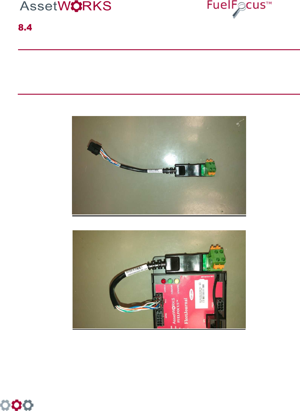
14. Connect the hardwire FIA
connector to the FleetJournal 3
[FJ3] ACC connector.
15. Install the hardwire FIA on the
FJ3 wall utilizing the magnetic
base.
16. Plug the fuel inlet antenna
wires into the green connection
points next to each other.

998 Old Eagle School Road, Suite 1215 | Wayne, Pennsylvania 19087 | T: 610-225-8350 | F: 610.971.9447 | www.assetworks.com
38
8.4.1 Troubleshooting
If the Hardwire FIA connection does not work [no proper signal], do the following:
3. Ensure that you are using a correct FIA and have a signal of at least 10 cm. If not replace the
FIA.
4. If there is still no proper signal, replace the FIA wire connection.
Note
The Fuel Inlet Antenna Connector is a sealed unit and cannot be repaired in
the field. Please return the defective units. Download an RMA from the
AssetWorks PartWorks website.

998 Old Eagle School Road, Suite 1215 | Wayne, Pennsylvania 19087 | T: 610-225-8350 | F: 610.971.9447 | www.assetworks.com
39
9 Connecting the FJ3 to the GPS
Tracking Device [Optional]
The GPS device tracks the location of vehicles in the field.
Figure 12 GPS Antenna Cable

998 Old Eagle School Road, Suite 1215 | Wayne, Pennsylvania 19087 | T: 610-225-8350 | F: 610.971.9447 | www.assetworks.com
40
To install the GPS tracking device:
3. Attach the RJ45 cable to the to the GPS connector on the FJ3.
4. Place the GPS antenna on the vehicle’s dashboard near the windshield.

998 Old Eagle School Road, Suite 1215 | Wayne, Pennsylvania 19087 | T: 610-225-8350 | F: 610.971.9447 | www.assetworks.com
41
10 Driver ID [Optional]
Connecting the Driver ID
To identify the driver of the vehicle, connect the Tag Reader wires to the FJ3 as
follows:
Wire Color Connect to:
White Dallas LED
Green Dallas In
Black (-) Bat Out
Red (+) Bat In
See Figure 13
Figure 13: Connecting the Driver ID reader to the FJ3

998 Old Eagle School Road, Suite 1215 | Wayne, Pennsylvania 19087 | T: 610-225-8350 | F: 610.971.9447 | www.assetworks.com
42
Installing the Driver ID Reader [Tag Reader]
Note: Place the Tag reader on the dashboard so that the Dallas key can be easily read.
6. Wire the Tag Reader cables to the FJ3 – see section Error! Reference source not found.
Error! Reference source not found..
7. Make a ½” hole on the dashboard for the Tag Reader.
8. Pull the Tag Reader through the hole.
9. Connect the Com. Cable ACC-CB-15A cable to the FJ3.
Figure 14 COM Cable ACC-CB-15A
10. Connect the Reader Cable ACC-CB-B7 to the Driver ID Reader.
Figure 15 Reader Cable ACC-CB-B7

998 Old Eagle School Road, Suite 1215 | Wayne, Pennsylvania 19087 | T: 610-225-8350 | F: 610.971.9447 | www.assetworks.com
43
Important: The Driver ID Reader should be bright red after connecting and installing it correctly. If
there is a faint green light in the center of the Reader, this indicates that the Reader is
not correctly installed. All the connectors should slide in smoothly, do not force them.

998 Old Eagle School Road, Suite 1215 | Wayne, Pennsylvania 19087 | T: 610-225-8350 | F: 610.971.9447 | www.assetworks.com
44
11 Appendices
Appendix A: Capturing Vehicle Data
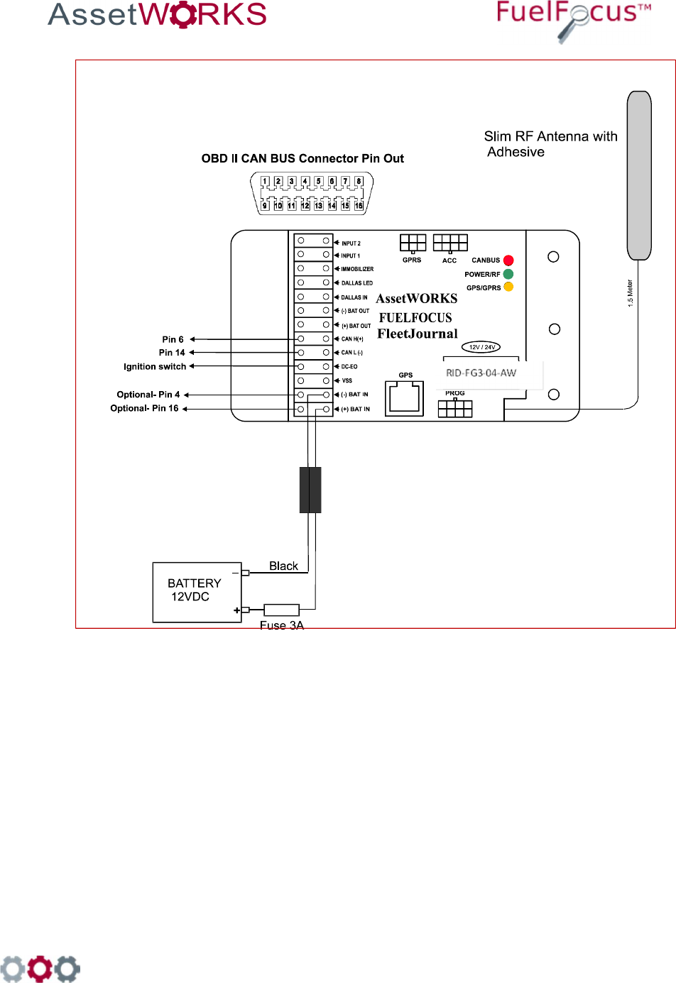
11.1.1 Connect the FJ3 to an OBD II Connector (Light Duty Vehicle)
If the vehicle has an OBD II connector, perform the following:
1. Run a twin wire cable from the vehicle connector to the FJ3.
2. Connect the FJ3 CAN_H to pin 6 of the OBD II connector.
3. Connect the FJ3 CAN_L to pin 14 of the OBD II connector.
Note
Optional Power Supply Connection
It is possible to supply the power to the FJ3 from the OBD II connector as
follows:
- Connect Pin 16 to BATT (+) on the FJ3.
- Connect Pin 4 to BATT (-) on the FJ3.
998 Old Eagle School Road, Suite 1215 | Wayne, Pennsylvania 19087 | T: 610-225-8350 | F: 610.971.9447 | www.assetworks.com
45
Figure 5: Wiring Diagram for FJ3 with CAN Bus Interface for Light Duty Vehicles
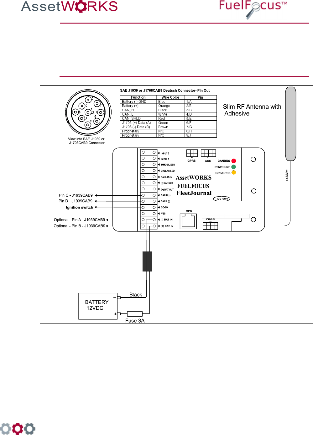
11.1.2 Connect the FJ3 to a J1939 Connector (Heavy Duty
Vehicle)
If the vehicle has a 9-pin Deutsch connector, perform the following:
1. Run a twin-wire cable from the vehicle connector to the FJ3.
2. Connect the CAN_H Black wire pin 3/C of the Deutsch connector to the FJ3 point
CAN_H.
3. Connect the CAN_L White wire pin 4/D of the Deutsch connector to the FJ3 point
CAN_L.
998 Old Eagle School Road, Suite 1215 | Wayne, Pennsylvania 19087 | T: 610-225-8350 | F: 610.971.9447 | www.assetworks.com
46
Note
Optional Power Supply Connection
It is possible to supply the power to the FJ3 from the J1939CAB9
connector as follows:
- Connect Pin 2/B to BATT (+) on the FJ3.
- Connect Pin 1/A to BATT (-) on the FJ3.
Figure 6: Wiring Diagram for FJ3 with CAN Bus Interface for Heavy Duty Vehicles
RID-FG3-04-AW
998 Old Eagle School Road, Suite 1215 | Wayne, Pennsylvania 19087 | T: 610-225-8350 | F: 610.971.9447 | www.assetworks.com
47
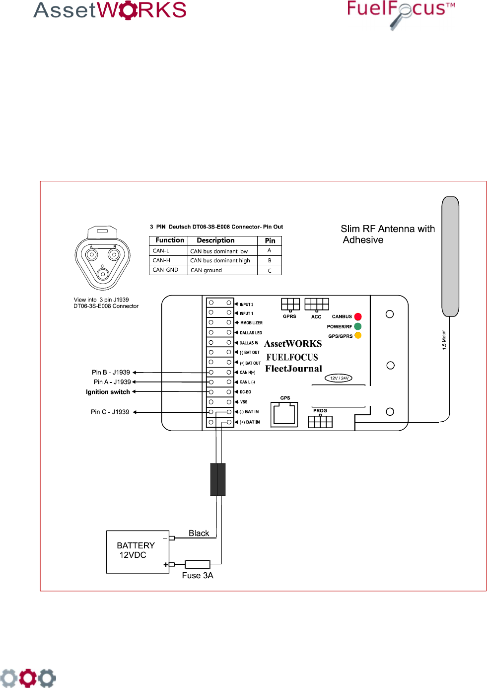
11.1.3 Connect the FJ3 to a 3 pin J1939 Connector (Heavy Duty
Vehicle)
If the vehicle has a 3-pin Deutsch connector, perform the following:
1. Run a twin-wire cable from the vehicle connector to the FJ3.
2. Connect the CAN_H pin B of the Deutsch connector to the FJ3 point CAN_H.
3. Connect the CAN_L pin A of the Deutsch connector to the FJ3 point CAN_L.
4. Connect the ground pin C of the Deutsch connector to the FJ3 point BATT (-).
Figure 7: Wiring Diagram for FJ3 with CAN Bus Interface (3-pin connector) for Heavy Duty Vehicles
RID-FG3-04-AW

998 Old Eagle School Road, Suite 1215 | Wayne, Pennsylvania 19087 | T: 610-225-8350 | F: 610.971.9447 | www.assetworks.com
48
12 Wiring J1708 Vehicles
Connect the Ignition Switch to the FJ3
Run a wire from the vehicle ignition switch to the DC-EO terminal on the FJ3 (see
Figure 2).
Note
FJ3 does not function properly if an ignition On/Off wire is not
connected. FJ3 goes into Sleep mode 30 min after turning off the
ignition.
Connect the Data Interface to the FJ3
The instructions for this procedure depend on the type of the connector equipped with
the vehicle – whether it is a J1708 CAB9 (9 pin) connector or a J1708 CAB (6 pin)
connector. The following sections provide instructions for both types of vehicles.
To view the connectors’ pin-out information, refer to the Fueling Options
Either SVID [Fuel Inlet Antenna Connector P/N RID-IN-54]
Or Hardwire [Fuel Intel Antenna
Connector P/N RID-EM-02]
Both options also require a Fuel Intel Antenna [P/N RVC-XX –XX]
SVID Mounting and Installation
12.3.1 Mounting the Fuel Inlet Antenna (FIA)
Note
Use shielded cable type Olympic part # 2886 or equivalent, polypropylene
insulated, twisted pair, aluminum Mylar shield, 20 – 22 AWG stranded
tinned copper drain wire, chrome vinyl jacket. Temperature rating: -20ºC to
60ºC.
Connect the FIA coil before mounting, to avoid using the heat gun
near the fuel tank. Before making this connection, plan on where
you are going to mount the SVID. Then make sure you have
clearance to pass the SVID from the filler neck to the mounting
location.
If you do not have enough clearance, first position the FIA coil on
the vehicle. Then pull the wire out to a safe distance (at least three
feet from the fuel filler neck) to heat the shrink-wrap insulation.
Then pull the wire back for final mounting.
Select a Fuel Inlet Antenna (FIA) with an internal diameter that allows it to fit snugly over the

998 Old Eagle School Road, Suite 1215 | Wayne, Pennsylvania 19087 | T: 610-225-8350 | F: 610.971.9447 | www.assetworks.com
49
filler neck. (A variety of sizes are available from AssetWorks.) Slide the FIA down over the filler
neck and slide it back until it is securely in place. (See note)
The intrinsically safe FIA wires must be tie wrapped at various locations between the FIA and
the SVID. One tie will be placed on the FIA wire, directly behind the antenna, to prevent the
antenna from falling off the filler neck.
Note
The FIA must be placed no more than four inches from the filler neck
opening. If the exposed portion of the filler neck pipe is longer than four
inches, place a plastic tie behind the antenna to hold it in place. You may
now install the odometer adaptor (if required) according to the
manufacturer's instructions. Then proceed to "Mounting the SVID".
12.3.2 Mounting the SVID
The location of the SVID will be determined according to the device type.
SVID with external antenna is mounted in the vehicle trunk or behind the fuel tank.
Important
The SVID should be mounted on the vehicle before performing the
activation.
12.3.3 FIA to SVID
Connect each of the intrinsically safe FIA wires to the "T-Ring" points (Polarity is not important)
at the SVID. Pass the SVID and its intrinsically safe cable to the selected mounting site. You
must find a clear path to run the cable from the fuel tank to the selected SVID mounting site.
You may use existing holes in the vehicle body. Make sure not to drill outer parts of the vehicle
and not to cause any damage to the operation of vehicle. Use grommets to protect cable that
you pass through holes. Remove plastic or rubber parts blocking the way. Make sure to re-
install all removed parts after the wires have been passed through.
Do not use an electric drill or any other electrical power tools within
3 feet of the filler neck or fuel tank as this area is considered a
Class I, Group D hazardous location.

998 Old Eagle School Road, Suite 1215 | Wayne, Pennsylvania 19087 | T: 610-225-8350 | F: 610.971.9447 | www.assetworks.com
50
12.3.4 SVID Installation
12.3.4.1 SVID Installation with external antenna wires on fuel tank
11.
Install the Fuel Inlet Antenna
– FIA ring on the fuel tank
inlet. Select the FIA ring
according to the vehicle type.
12.
Route the FIA wires through a
protective conduit under
vehicle chassis to the SVID.
13.
Clean the surface of the
vehicle with alcohol; make
sure to remove all grease
and debris.
14.
Remove the sticker on the
back of the SVID device and
stick it to the cleaned surface
as shown.
15.
Connect the SVID antenna
wires with FIA wires using
two suitable connectors.

998 Old Eagle School Road, Suite 1215 | Wayne, Pennsylvania 19087 | T: 610-225-8350 | F: 610.971.9447 | www.assetworks.com
51
12.3.4.2
SVID Installation With External Antenna Wires on the Vehicle Trunk
9.
Install the fuel inlet antenna -FIA
ring on the fuel tank inlet. Select
a ring according to the vehicle
type.
10.
Drill 7mm hole in fueling
compartment, insert a grommet,
and insert the 2 wires. Install the
SVID in the vehicle trunk behind
the fuel inlet.
11.
Clean the surface of the vehicle
with alcohol. Make sure to
remove all grease and debris.
12.
Connect the SVID antenna wires
to the FIA ring wires with two
suitable connectors using
crimping tool.

998 Old Eagle School Road, Suite 1215 | Wayne, Pennsylvania 19087 | T: 610-225-8350 | F: 610.971.9447 | www.assetworks.com
52
12.3.4.3 FIA Installation on a Light Duty Vehicle Fuel Tank

998 Old Eagle School Road, Suite 1215 | Wayne, Pennsylvania 19087 | T: 610-225-8350 | F: 610.971.9447 | www.assetworks.com
53
12.3.4.4 Installation on a Heavy Duty Vehicle Fuel Tank

998 Old Eagle School Road, Suite 1215 | Wayne, Pennsylvania 19087 | T: 610-225-8350 | F: 610.971.9447 | www.assetworks.com
54
Hardwire Fuel Inlet Antenna Connector
Installation Instructions
FCC Compliance
FCC ID: 2AKAM2288

998 Old Eagle School Road, Suite 1215 | Wayne, Pennsylvania 19087 | T: 610-225-8350 | F: 610.971.9447 | www.assetworks.com
55
To install the Hardwire FIA:
17. Select a fuel inlet antenna diameter to fit the vehicle’s fuel tank inlet [one size larger].
18. Install it using the dedicated snaps provided.
19. Make sure the fuel inlet antenna cable is long enough to reach the location where the
FleetJournal 3 will be installed.
Note
If necessary the cable may be extended. Use shielded cable type Olympic
part # 2886 or equivalent, polypropylene insulated, twisted pair, aluminum
Mylar shield, 20 – 22 AWG stranded tinned copper drain wire, chrome vinyl
jacket. Temperature rating: -20ºC to 60ºC.
20. Solder and/or use moisture. To prevent connection problems in the future, proof the
connections and if necessary shrink the tubing.
21. Install the FleetJournal 3. See Chapter 3 FJ3 Installation.
22. Connect the hardwire FIA
connector to the FleetJournal 3
[FJ3] ACC connector.
23. Install the hardwire FIA on the
FJ3 wall utilizing the magnetic
base.
24. Plug the fuel inlet antenna
wires into the green connection
points next to each other.

998 Old Eagle School Road, Suite 1215 | Wayne, Pennsylvania 19087 | T: 610-225-8350 | F: 610.971.9447 | www.assetworks.com
56
12.4.1 Troubleshooting
If the Hardwire FIA connection does not work [no proper signal], do the following:
5. Ensure that you are using a correct FIA and have a signal of at least 10 cm. If not replace the
FIA.
6. If there is still no proper signal, replace the FIA wire connection.
Note
The Fuel Inlet Antenna Connector is a sealed unit and cannot be repaired in
the field. Please return the defective units. Download an RMA from the
AssetWorks PartWorks website.
998 Old Eagle School Road, Suite 1215 | Wayne, Pennsylvania 19087 | T: 610-225-8350 | F: 610.971.9447 | www.assetworks.com
57
13 Connecting the FJ3 to the GPS
Tracking Device [Optional]
The GPS device tracks the location of vehicles in the field.
Figure 12 GPS Antenna Cable
998 Old Eagle School Road, Suite 1215 | Wayne, Pennsylvania 19087 | T: 610-225-8350 | F: 610.971.9447 | www.assetworks.com
58
To install the GPS tracking device:
5. Attach the RJ45 cable to the to the GPS connector on the FJ3.
6. Place the GPS antenna on the vehicle’s dashboard near the windshield.
998 Old Eagle School Road, Suite 1215 | Wayne, Pennsylvania 19087 | T: 610-225-8350 | F: 610.971.9447 | www.assetworks.com
59
14 Driver ID [Optional]
Connecting the Driver ID
To identify the driver of the vehicle, connect the Tag Reader wires to the FJ3 as
follows:
Wire Color Connect to:
White Dallas LED
Green Dallas In
Black (-) Bat Out
Red (+) Bat In
See Figure 13
Figure 13: Connecting the Driver ID reader to the FJ3
998 Old Eagle School Road, Suite 1215 | Wayne, Pennsylvania 19087 | T: 610-225-8350 | F: 610.971.9447 | www.assetworks.com
60
Installing the Driver ID Reader [Tag Reader]
Note: Place the Tag reader on the dashboard so that the Dallas key can be easily read.
11. Wire the Tag Reader cables to the FJ3 – see section Error! Reference source not found.
Error! Reference source not found..
12. Make a ½” hole on the dashboard for the Tag Reader.
13. Pull the Tag Reader through the hole.
14. Connect the Com. Cable ACC-CB-15A cable to the FJ3.
Figure 14 COM Cable ACC-CB-15A
15. Connect the Reader Cable ACC-CB-B7 to the Driver ID Reader.
Figure 15 Reader Cable ACC-CB-B7

998 Old Eagle School Road, Suite 1215 | Wayne, Pennsylvania 19087 | T: 610-225-8350 | F: 610.971.9447 | www.assetworks.com
61
Important: The Driver ID Reader should be bright red after connecting and installing it correctly. If
there is a faint green light in the center of the Reader, this indicates that the Reader is
not correctly installed. All the connectors should slide in smoothly, do not force them.

998 Old Eagle School Road, Suite 1215 | Wayne, Pennsylvania 19087 | T: 610-225-8350 | F: 610.971.9447 | www.assetworks.com
62
15 Appendices
Appendix A: Capturing Vehicle Data
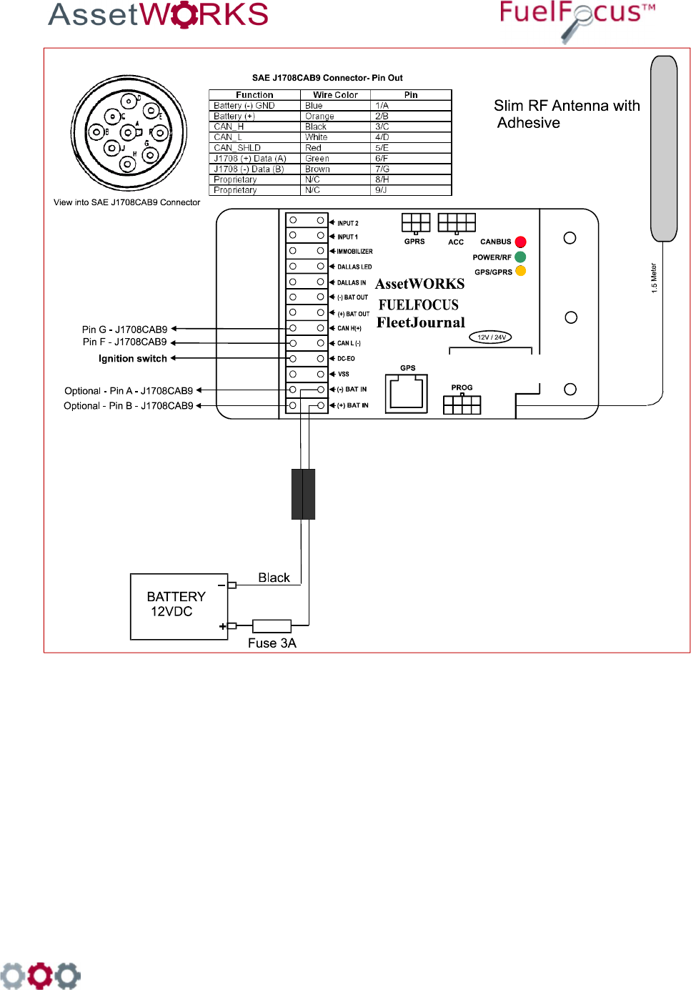
15.1.1 Connect the FJ3 to the J1708 CAB9 Connector
If the vehicle has 9 pin Deutsch connector, perform the following:
1. Run a twin wire cable from the vehicle connector to the FJ3.
2. Connect the J1708 Data link (+) wire from pin F of the Deutsch connector.
3. Connect the J1708 Data link (-) wire from pin G of the Deutsch connector.
Note
Optional Power Supply Connection
It is possible to supply the power to the FJ3 from the J1708CAB9 if pin 2/B has
12-24 volts with the ignition in the off position:
- Connect Pin 2/B to BATT (+) on the FJ3.
- Connect Pin 1/A to BATT (-) on the FJ3.
998 Old Eagle School Road, Suite 1215 | Wayne, Pennsylvania 19087 | T: 610-225-8350 | F: 610.971.9447 | www.assetworks.com
63
Figure 8: Wiring Diagram for FJ3 to J1708CAB9 (9 pin) connector
RID-FG3-04-AW
998 Old Eagle School Road, Suite 1215 | Wayne, Pennsylvania 19087 | T: 610-225-8350 | F: 610.971.9447 | www.assetworks.com
64
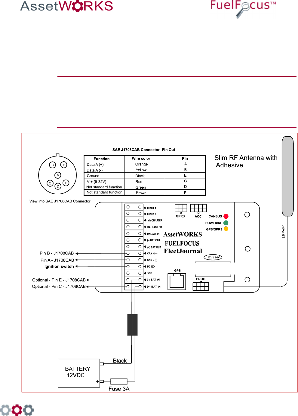
15.1.2 Connect the FJ3 to the J1708 CAB Connector
If the vehicle has a 6-pin Deutsch connector, perform the following:
1. Run a twin-wire cable from the vehicle connector to the FJ3.
2. Connect the J1708 Data link (+) wire from pin A of the Deutsch connector.
3. Connect the J1708 Data link (-) wire from pin B of the Deutsch connector.
Note
Optional Power Supply Connection
The power supply can be connected to FJ3 from the J1708 CAB
connector, if pin C provides 12 – 24 volts with the ignition in the off
position:
- Connect Pin C to BATT (+) on the FJ3.
- Connect Pin E to BATT (-) on the FJ3.
Figure 9: Wiring Diagram for FJ3 to J1708CAB (6 pin) connector
RID-FG3-04-AW

998 Old Eagle School Road, Suite 1215 | Wayne, Pennsylvania 19087 | T: 610-225-8350 | F: 610.971.9447 | www.assetworks.com
65
16 Completion of Installation
Verify Installation
Upon completing installation, verify that the GREEN LED on the FJ3 is blinking every
second. This indicates good power and grounding.
There are three indicator LEDs on the FJ3 (see
Figure 2
on page 11) one green LED,
one red LED and one orange LED:
LED COLOR FUNCTION INDICATION
RED
CANBUS
• Blinks every second when no data
received.
• Blinks according to the data transfer rate
when receiving data.
GREEN
Power and RF
RF transmission - Fast blinking Power ON -
Blinks every second
ORANGE
GPS/GPRS
Blinks when GPS unit is connected and data
from the GPS is transmitted
Note
During normal operations, the green LED also blinks every time an
RF message is received, indicating that the FJ3 is communicating
with the WAF or VDC antenna.
After power up, the green LED blinks every second. (Indicating
power and ground are connected).
The green LED also blinks every time an RF message is received.
(Indicating the FJ3 is communicating with the WAF or VDC antenna)
When FJ3 is set to Hour counter using the VSS input, the red LED is on.
(This indicates good communication with the vehicle/equipment.)
998 Old Eagle School Road, Suite 1215 | Wayne, Pennsylvania 19087 | T: 610-225-8350 | F: 610.971.9447 | www.assetworks.com
66
17 FJ3 Flashing Tool
Purpose
The FJ3 Flashing Tool is part of the FuelFocus Vehicle Subsystem. These instructions explain how
to upload a new FJ3 version for the flashing tool and how to program the FJ3 after the new version
has been loaded.
Preparation steps
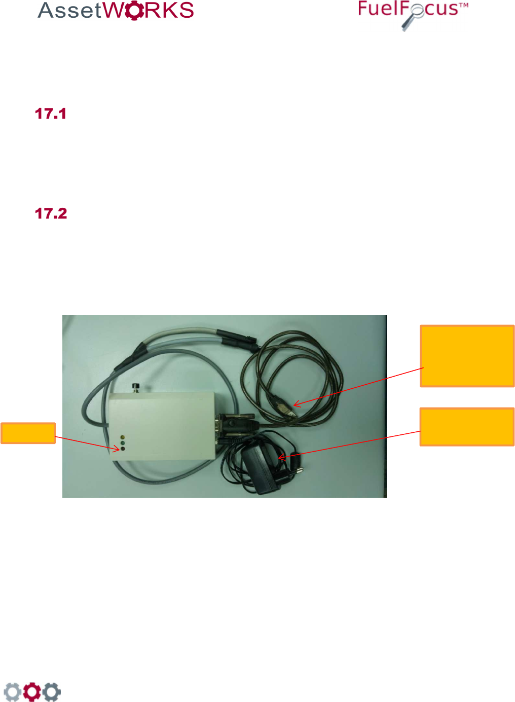
1. Connect a USB cable from the Flashing tool to your computer
2. Connect the Flashing tool to a 12V Power Supply
3. Locate the flashing tool software on your computer - ProgCa_UmArm.exe
Figure 10: Flashing Tool Preparation
Flashing Tool
#PRG-FG3-04
USB cable
GNR0094
to the
Computer
12 V Power
Supply
Pow
er
998 Old Eagle School Road, Suite 1215 | Wayne, Pennsylvania 19087 | T: 610-225-8350 | F: 610.971.9447 | www.assetworks.com
67
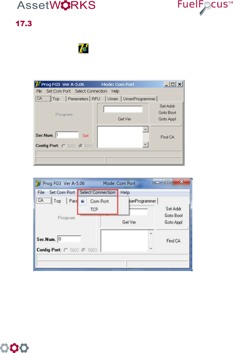
Updating the FJ3 Flash Tool Version
1. Verify that the Flashing Tool program files have been installed on your comuter
2. Double click
ProgUm5_.06.exe
icon or ProgCa_UmArm.exe. The Prog FG3 Ver A-5.06 window
is displayed.
3. Click Select Connection >Com Port
998 Old Eagle School Road, Suite 1215 | Wayne, Pennsylvania 19087 | T: 610-225-8350 | F: 610.971.9447 | www.assetworks.com
68
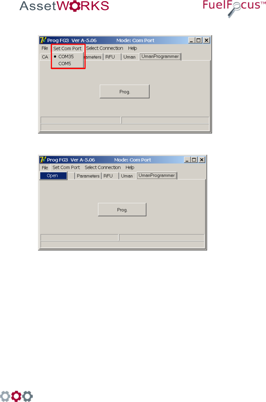
4. Click Set Com Port and select an available port on your comuter, such as COM35.
5. Click File > Open
998 Old Eagle School Road, Suite 1215 | Wayne, Pennsylvania 19087 | T: 610-225-8350 | F: 610.971.9447 | www.assetworks.com
69
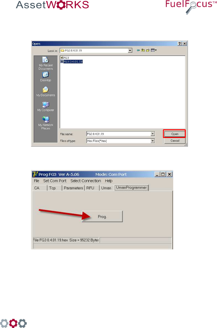
6. The Open file dialog box is displayed.
a. Select the FG3 hex file, for example: FG3 0.4.01.19.hex
b. Click Open to continue.
Click Prog to start the updating process.
998 Old Eagle School Road, Suite 1215 | Wayne, Pennsylvania 19087 | T: 610-225-8350 | F: 610.971.9447 | www.assetworks.com
70
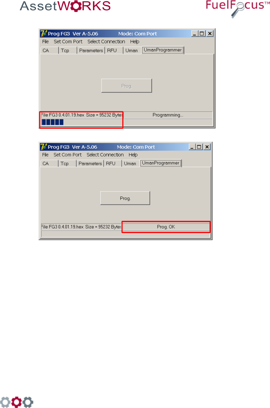
Verify that the status bar shows the progress.
8. Verify that the status bar shows Prog. OK
998 Old Eagle School Road, Suite 1215 | Wayne, Pennsylvania 19087 | T: 610-225-8350 | F: 610.971.9447 | www.assetworks.com
71
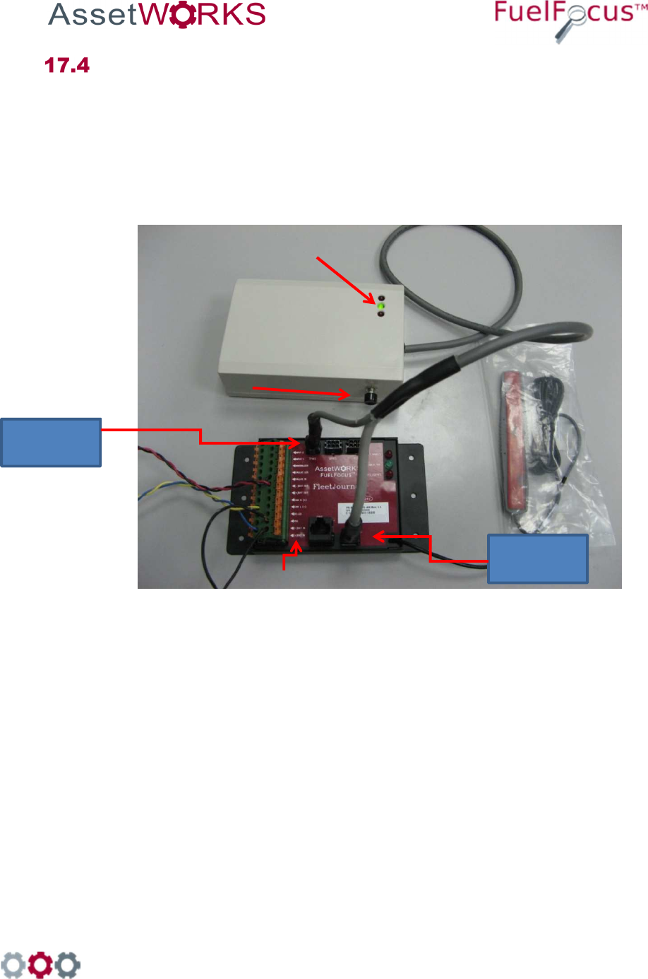
Instructions for Flash Tool FJ3 Box V1
FOR FJ3 with p/n RID-FG3-04-AW you will use both cables from the Flash Tool
1. Connect the two cables of the Flash Tool # PRG-FG3-04 to the FJ3 as shown:
Connect the 4 pin plug to TPMS connector
Connect the 6 pin plug to the PROG connector
2. Ensure that the FJ3 has 12V by validating the red light is lit on the flash tool
3. Press the black flash push Button for 2 seconds. The green light will blink during the flashing
process. When flashing is complete, the green light will stay lit (solid).
Figure 11 Flash Tool Connections
Flash
Tool
#PRG-FG3-04
Power In 12V
Indicator LED'S
PRG
TPMS
Flashing Push Button

998 Old Eagle School Road, Suite 1215 | Wayne, Pennsylvania 19087 | T: 610-225-8350 | F: 610.971.9447 | www.assetworks.com
72
Instructions for Flash Tool FJ3 Box V4 and Above
For FJ3 with - p/n RID-FG3-04–AW
and up with a single 6-pin PRG cable:
1. Connect the 6-pin plug of the Flash Tool # PRG-FG3-04 to the FJ3 into the PRG
connector.
2. Ensure that the FJ3 has 12V by validating the red light is lit on flash tool
3. Press the black flash push Button for 2 seconds. The green light will blink during the
flashing process. When flashing is complete, the green light stays lit (solid).
GREEN LED and RED LED on the Flashing Tool:
LED
COLOR
FUNCTION
INDICATION
RED Power Blinks when the Flash Tool is receiving power
GREEN
Flashing
• After pressing the black push button, the
green LED blinks while the Flash tool is
connected to the FJ3
• The green LED turns solid after flashing
completes successfully

998 Old Eagle School Road, Suite 1215 | Wayne, Pennsylvania 19087 | T: 610-225-8350 | F: 610.971.9447 | www.assetworks.com
73
18 Fueling Options
• Either SVID [Fuel Inlet Antenna Connector P/N RID-IN-54]
• Or Hardwire [Fuel Intel Antenna Connector P/N RID-EM-02]
Both options also require a Fuel Intel Antenna [P/N RVC-XX –XX]
SVID Mounting and Installation
18.1.1 Mounting the Fuel Inlet Antenna (FIA)
Note
Use shielded cable type Olympic part # 2886 or equivalent, polypropylene
insulated, twisted pair, aluminum Mylar shield, 20 – 22 AWG stranded
tinned copper drain wire, chrome vinyl jacket. Temperature rating: -20ºC to
60ºC.
Connect the FIA coil before mounting, to avoid using the heat gun
near the fuel tank. Before making this connection, plan on where
you are going to mount the SVID. Then make sure you have
clearance to pass the SVID from the filler neck to the mounting
location.
If you do not have enough clearance, first position the FIA coil on
the vehicle. Then pull the wire out to a safe distance (at least three
feet from the fuel filler neck) to heat the shrink-wrap insulation.
Then pull the wire back for final mounting.
Select a Fuel Inlet Antenna (FIA) with an internal diameter that allows it to fit snugly over the
filler neck. (A variety of sizes are available from AssetWorks.) Slide the FIA down over the filler
neck and slide it back until it is securely in place. (See note)
The intrinsically safe FIA wires must be tie wrapped at various locations between the FIA and
the SVID. One tie will be placed on the FIA wire, directly behind the antenna, to prevent the
antenna from falling off the filler neck.
Note
The FIA must be placed no more than four inches from the filler neck
opening. If the exposed portion of the filler neck pipe is longer than four
inches, place a plastic tie behind the antenna to hold it in place. You may
now install the odometer adaptor (if required) according to the
manufacturer's instructions. Then proceed to "Mounting the SVID".

998 Old Eagle School Road, Suite 1215 | Wayne, Pennsylvania 19087 | T: 610-225-8350 | F: 610.971.9447 | www.assetworks.com
74
18.1.2 Mounting the SVID
The location of the SVID will be determined according to the device type.
SVID with external antenna is mounted in the vehicle trunk or behind the fuel tank.
Important
The SVID should be mounted on the vehicle before performing the
activation.
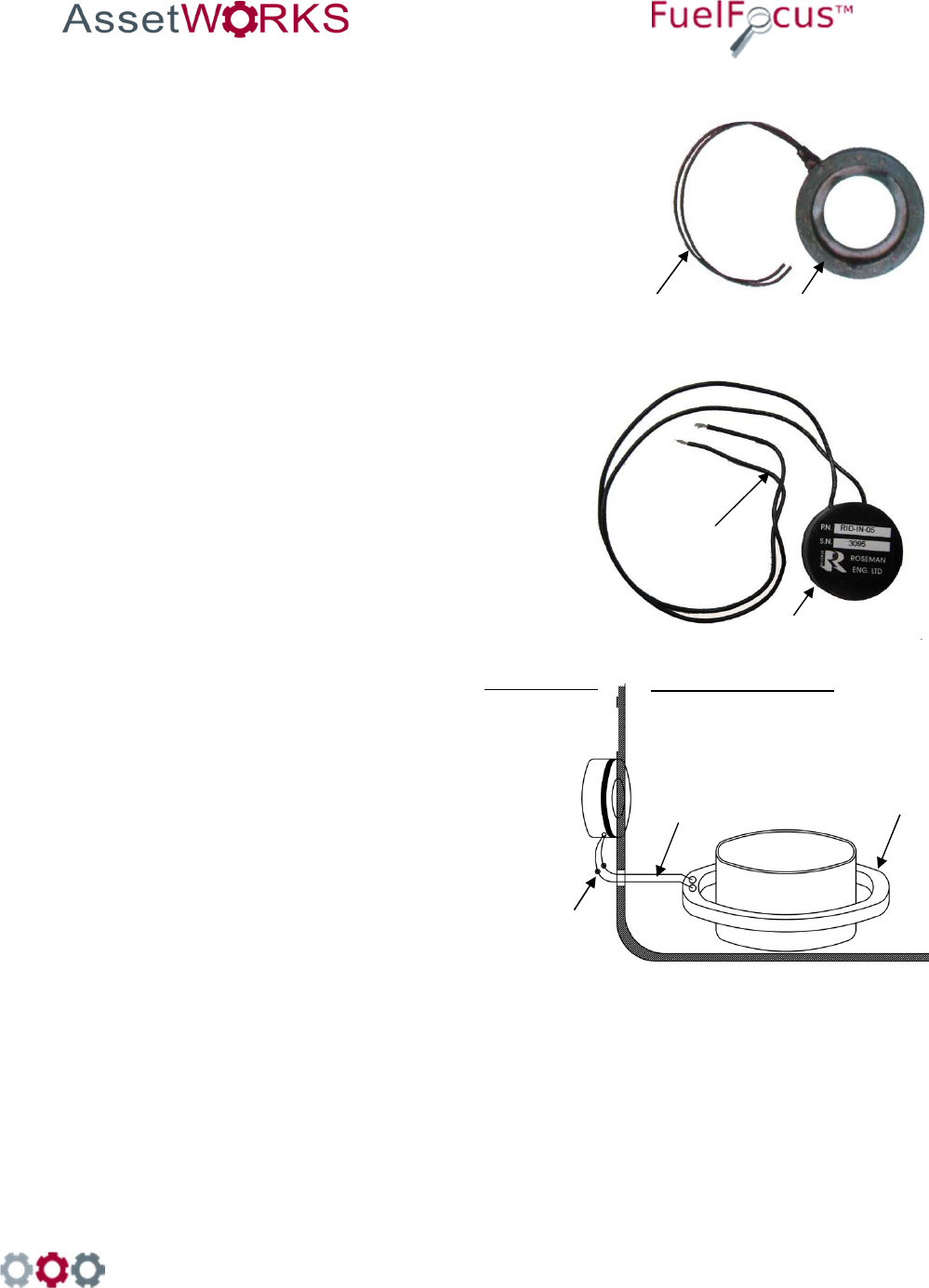
18.1.3 FIA to SVID
Connect each of the intrinsically safe FIA wires to the "T-Ring" points (Polarity is not important)
at the SVID. Pass the SVID and its intrinsically safe cable to the selected mounting site. You
must find a clear path to run the cable from the fuel tank to the selected SVID mounting site.
You may use existing holes in the vehicle body. Make sure not to drill outer parts of the vehicle
and not to cause any damage to the operation of vehicle. Use grommets to protect cable that
you pass through holes. Remove plastic or rubber parts blocking the way. Make sure to re-
install all removed parts after the wires have been passed through.
Do not use an electric drill or any other electrical power tools within
3 feet of the filler neck or fuel tank as this area is considered a
Class I, Group D hazardous location.
998 Old Eagle School Road, Suite 1215 | Wayne, Pennsylvania 19087 | T: 610-225-8350 | F: 610.971.9447 | www.assetworks.com
75
18.1.4 SVID Installation
18.1.4.1 SVID Installation with external antenna wires on fuel tank
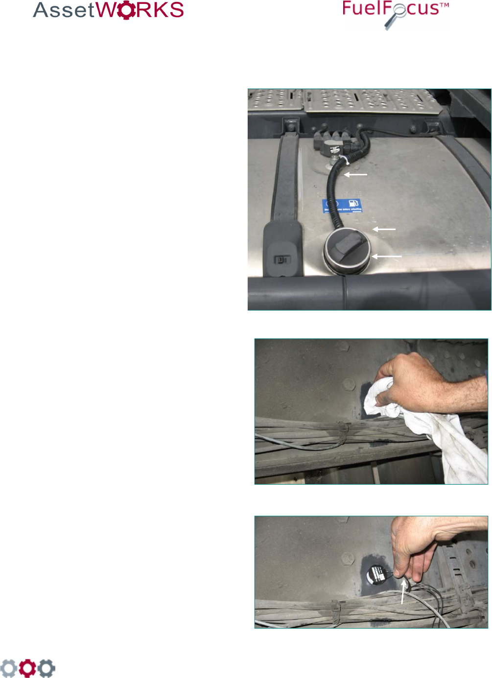
16.
Install the Fuel Inlet Antenna
– FIA ring on the fuel tank
inlet. Select the FIA ring
according to the vehicle type.
17.
Route the FIA wires through a
protective conduit under
vehicle chassis to the SVID.
18.
Clean the surface of the
vehicle with alcohol; make
sure to remove all grease
and debris.
19.
Remove the sticker on the
back of the SVID device and
stick it to the cleaned surface
as shown.
20.
Connect the SVID antenna
wires with FIA wires using
two suitable connectors.
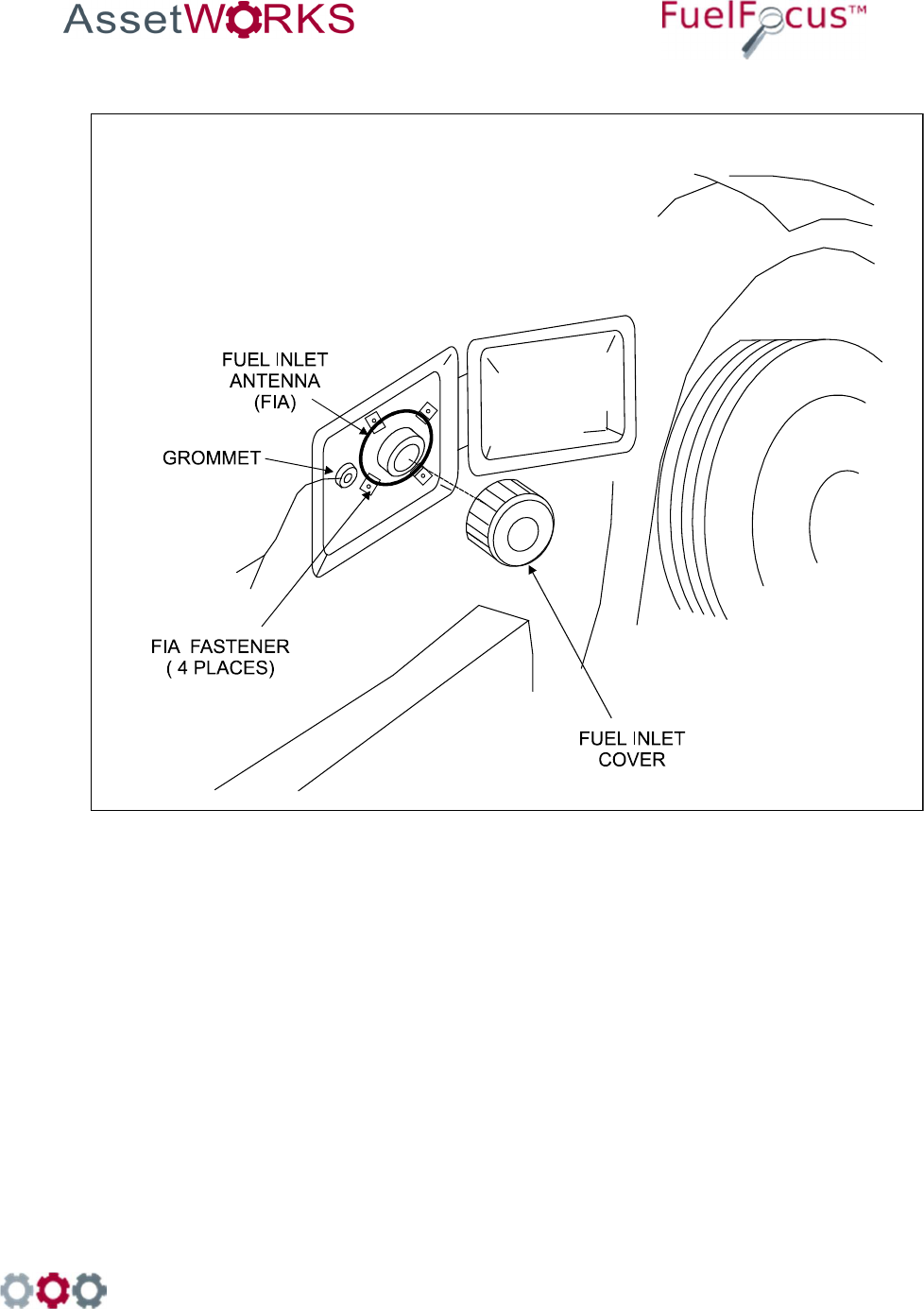
SVID antenna wires
Fuel inlet cover
FIA ring
Protective conduit
998 Old Eagle School Road, Suite 1215 | Wayne, Pennsylvania 19087 | T: 610-225-8350 | F: 610.971.9447 | www.assetworks.com
76
18.1.4.2
SVID Installation With External Antenna Wires on the Vehicle Trunk
13.
Install the fuel inlet antenna -FIA
ring on the fuel tank inlet. Select
a ring according to the vehicle
type.
14.
Drill 7mm hole in fueling
compartment, insert a grommet,
and insert the 2 wires. Install the
SVID in the vehicle trunk behind
the fuel inlet.
15.
Clean the surface of the vehicle
with alcohol. Make sure to
remove all grease and debris.
16.
Connect the SVID antenna wires
to the FIA ring wires with two
suitable connectors using
crimping tool.
Antenna Ring
Fueling compartment
Fuel inlet
Antenna wires
Antenna Ring
Antenna wires
FIA Ring
Antenna wires
Connectors
SVID
Vehicle trunk
SVID

998 Old Eagle School Road, Suite 1215 | Wayne, Pennsylvania 19087 | T: 610-225-8350 | F: 610.971.9447 | www.assetworks.com
77
18.1.4.3 FIA Installation on a Light Duty Vehicle Fuel Tank

998 Old Eagle School Road, Suite 1215 | Wayne, Pennsylvania 19087 | T: 610-225-8350 | F: 610.971.9447 | www.assetworks.com
78
18.1.4.4 Installation on a Heavy Duty Vehicle Fuel Tank

998 Old Eagle School Road, Suite 1215 | Wayne, Pennsylvania 19087 | T: 610-225-8350 | F: 610.971.9447 | www.assetworks.com
79
Hardwire Fuel Inlet Antenna Connector
Installation Instructions
FCC Compliance
FCC ID: 2AKAM2288

998 Old Eagle School Road, Suite 1215 | Wayne, Pennsylvania 19087 | T: 610-225-8350 | F: 610.971.9447 | www.assetworks.com
80
To install the Hardwire FIA:
25. Select a fuel inlet antenna diameter to fit the vehicle’s fuel tank inlet [one size larger].
26. Install it using the dedicated snaps provided.
27. Make sure the fuel inlet antenna cable is long enough to reach the location where the
FleetJournal 3 will be installed.
Note
If necessary the cable may be extended. Use shielded cable type Olympic
part # 2886 or equivalent, polypropylene insulated, twisted pair, aluminum
Mylar shield, 20 – 22 AWG stranded tinned copper drain wire, chrome vinyl
jacket. Temperature rating: -20ºC to 60ºC.
28. Solder and/or use moisture. To prevent connection problems in the future, proof the
connections and if necessary shrink the tubing.
29. Install the FleetJournal 3. See Chapter 3 FJ3 Installation.
30. Connect the hardwire FIA
connector to the FleetJournal 3
[FJ3] ACC connector.
31. Install the hardwire FIA on the
FJ3 wall utilizing the magnetic
base.
32. Plug the fuel inlet antenna
wires into the green connection
points next to each other.
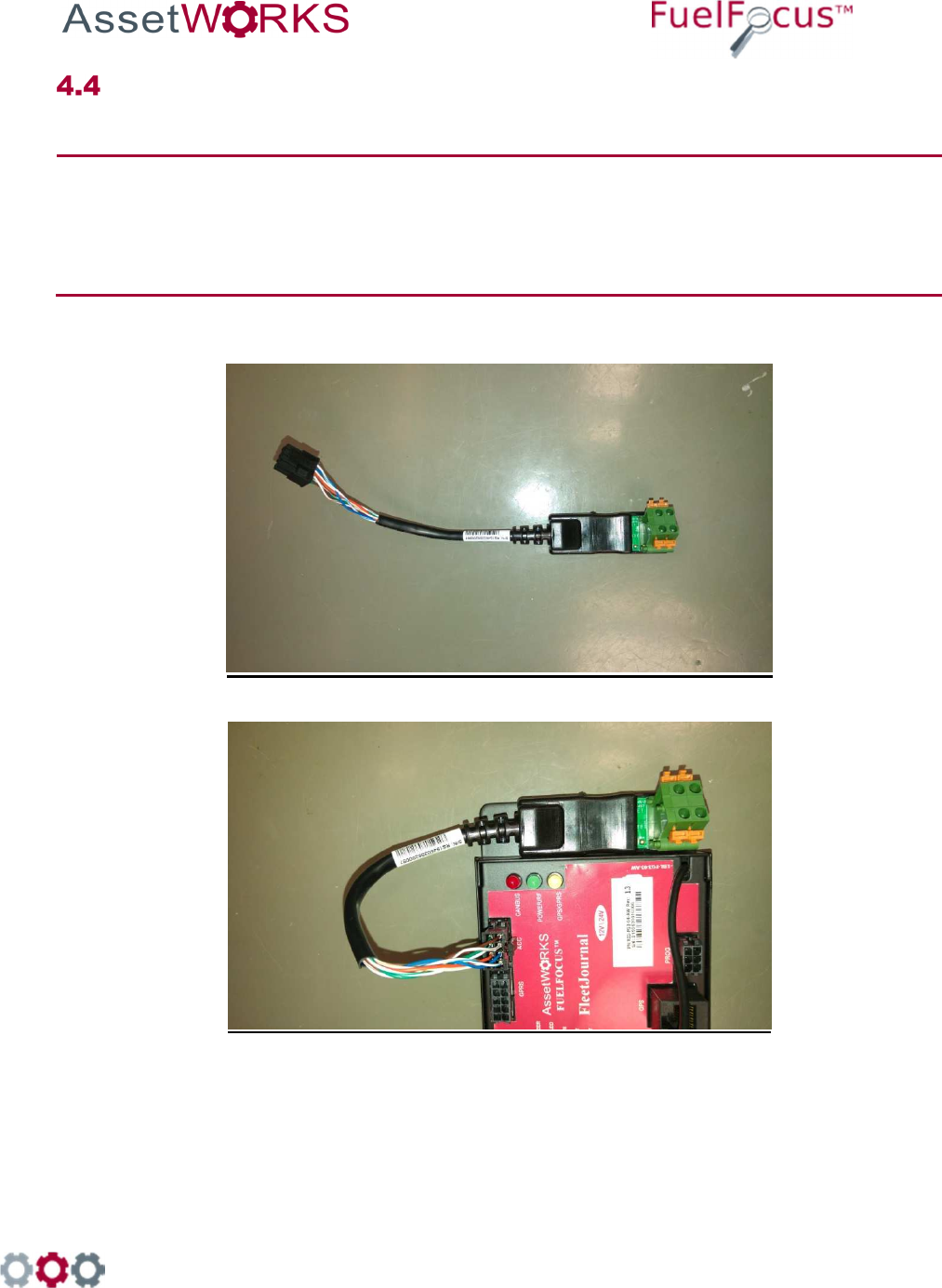
Hardwire
FIA connector plus
and ACC connector
FIA wire
connection points

998 Old Eagle School Road, Suite 1215 | Wayne, Pennsylvania 19087 | T: 610-225-8350 | F: 610.971.9447 | www.assetworks.com
81
18.2.1 Troubleshooting
If the Hardwire FIA connection does not work [no proper signal], do the following:
7. Ensure that you are using a correct FIA and have a signal of at least 10 cm. If not replace the
FIA.
8. If there is still no proper signal, replace the FIA wire connection.
Note
The Fuel Inlet Antenna Connector is a sealed unit and cannot be repaired in
the field. Please return the defective units. Download an RMA from the
AssetWorks PartWorks website.
Magnets
FIA Wire Connections

998 Old Eagle School Road, Suite 1215 | Wayne, Pennsylvania 19087 | T: 610-225-8350 | F: 610.971.9447 | www.assetworks.com
82
19 Connecting the FJ3 to the GPS
Tracking Device [Optional]
The GPS device tracks the location of vehicles in the field.
Figure 12 GPS Antenna Cable

998 Old Eagle School Road, Suite 1215 | Wayne, Pennsylvania 19087 | T: 610-225-8350 | F: 610.971.9447 | www.assetworks.com
83
To install the GPS tracking device:
7. Attach the RJ45 cable to the to the GPS connector on the FJ3.
8. Place the GPS antenna on the vehicle’s dashboard near the windshield.

998 Old Eagle School Road, Suite 1215 | Wayne, Pennsylvania 19087 | T: 610-225-8350 | F: 610.971.9447 | www.assetworks.com
84
20 Driver ID [Optional]
Connecting the Driver ID
To identify the driver of the vehicle, connect the Tag Reader wires to the FJ3 as
follows:
Wire Color Connect to:
White Dallas LED
Green Dallas In
Black (-) Bat Out
Red (+) Bat In
See Figure 13
Figure 13: Connecting the Driver ID reader to the FJ3
RID-FG3-04-AW

998 Old Eagle School Road, Suite 1215 | Wayne, Pennsylvania 19087 | T: 610-225-8350 | F: 610.971.9447 | www.assetworks.com
85
Installing the Driver ID Reader [Tag Reader]
Note: Place the Tag reader on the dashboard so that the Dallas key can be easily read.
16. Wire the Tag Reader cables to the FJ3 – see section Error! Reference source not found.
Error! Reference source not found..
17. Make a ½” hole on the dashboard for the Tag Reader.
18. Pull the Tag Reader through the hole.
19. Connect the Com. Cable ACC-CB-15A cable to the FJ3.
Figure 14 COM Cable ACC-CB-15A
20. Connect the Reader Cable ACC-CB-B7 to the Driver ID Reader.
Figure 15 Reader Cable ACC-CB-B7

998 Old Eagle School Road, Suite 1215 | Wayne, Pennsylvania 19087 | T: 610-225-8350 | F: 610.971.9447 | www.assetworks.com
86
Important: The Driver ID Reader should be bright red after connecting and installing it correctly. If
there is a faint green light in the center of the Reader, this indicates that the Reader is
not correctly installed. All the connectors should slide in smoothly, do not force them.

998 Old Eagle School Road, Suite 1215 | Wayne, Pennsylvania 19087 | T: 610-225-8350 | F: 610.971.9447 | www.assetworks.com
87
21 Appendices
Appendix A: Capturing Vehicle Data
21.1.1 Capturing Odometer and Engine Hours Information
If the FJ3 is to record the vehicle's odometer, you will need to obtain a pulse relevant to the
vehicle’s speed. You can accomplish this either by utilizing an Odometer Adaptor or by
receiving electronic pulses from the vehicle speed sensor (VSS) output. If your vehicle has a
cable driven speedometer, a transducer is needed to convert the mechanical turns of the
speedometer cable into electronic pulses that the FJ3 can read. Transducers may be ordered
through a local speedometer repair shop, through the vehicle manufacturer's parts distributor,
or directly from the sensor manufacturer.
21.1.2 Vehicle Data Collection (VDC) - Option
The AssetWorks VDC enables online wireless capture of odometer and/or engine hour
readings from vehicles equipped with the AssetWorks Vehicle Identification Fleet Gate (FJ3).
This data capture occurs when a vehicle passes within range of the Wireless Automated
Fueling (WAF) Receiver installed in a parking area or at a fuel island. The vehicle data is
transmitted to a local PC, which has the AssetWorks proprietary VSU application, and will
transmit it to the FleetFocus™ application server via TCP/IP protocol.
21.1.3 Vehicle Speed Sensor (VSS)
For FJ3 pulse counting to function properly, it requires an accurate speed signal from the
vehicle. This section provides a quick overview of what a speed signal is, and how to identify
a speed signal.
With the introduction of the electronic control module (ECM/ECU) found in all modern vehicles,
engineers use sensors to report operational data to this computer for processing.
In most cases, the vehicle’s speed signal is generated at the transmission output shaft. The
shaft turns at a speed directly proportional to the vehicle speed. Two different sensor types are
commonly found at this location. The most common type is called a variable reluctance
sensor. This is a fancy name for a series of magnets mounted to “shag”, which spins past an
inductor or coil. A voltage or pulse is induced in the circuit as the magnets’ lines of force cut
through the inductor. The end result is a signal that pulsates or oscillates at a speed directly
proportional to vehicle speed. The more modern but less common type of sensor is the Hall
Effect sensor, which works like the variable reluctance sensor, uses a tiny solid state switch
that is activated by a magnetic force. This result is a smaller and lighter sensor, generating a
cleaner signal.
There are many ways to identify the vehicle speed signal:
21.1.3.1 Using an Oscilloscope
Using an Oscilloscope is the easiest way to view and identify the VSS signal. It
shows a picture of the signal.
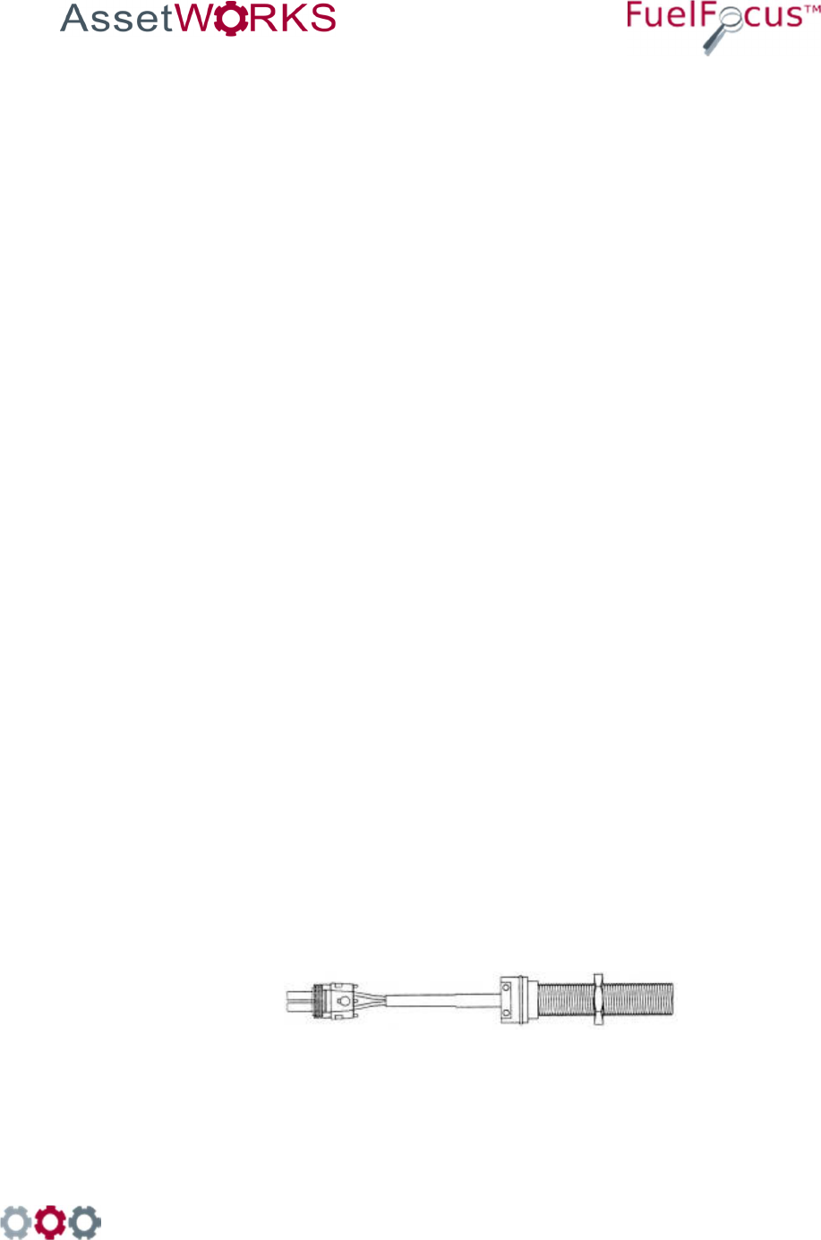
998 Old Eagle School Road, Suite 1215 | Wayne, Pennsylvania 19087 | T: 610-225-8350 | F: 610.971.9447 | www.assetworks.com
88
21.1.3.2 Using a Multi-Meter to Measure Frequency (Hz)
This is the easiest way to measure the speed signal without the use of a scope, but
watch out for some things. The meter may give incorrect readings at rest. The meter
uses A/C coupling to measure frequency, so it may try to measure noise to determine
its frequency. It is most important to measure frequency while the vehicle is moving.
The frequency increases proportionately to vehicle speed. If the measurements seem
to bounce around, you probably don't have the correct circuit.
21.1.3.3 Using a Multi-Meter to Measure A/C Voltage
This is another way to verify the VSS circuit. This method works poorly with Hall
Sensor outputs. This is because a Hall Sensor’s output varies in frequency but not
amplitude. Most A/C Mustimeters display voltage in RMS, which is about 70% of the
peak value of the A/C waveform. Since the peak voltage is constant with a Hall
Sensor, you will see only two readings; the reading while the vehicle is stationary,
and the reading while it is in motion. This is usually enough data to determine if you
have the right circuit.
Using an A/C Multimeter to test a variable reluctance sensor, which are the most
common, will work very well. As with frequency, A/C voltage should fluctuate in direct
proportion to the vehicle speed.
Upon identifying the VSS circuit, then determine the number of pulses per mile that
the sensor emits. To determine the speed and mileage, the VIB must know how
many pulses are emitted for a mile traveled. There are only a few different calibration
values. Most Ford and Chrysler products emit 8000 pulses per mile. Chevrolet
commonly uses 4000 at the control module, and 96000 at the transmission.
21.1.3.4 Electronic Odometer Adapter
If the vehicle is equipped with an electronic sending unit controlling the dashboard
speedometer, simply connect a wire between the signal line and the FJ3. If the
vehicle's electronic odometer line is also driving additional equipment, such as a
cruise control module or trip computer, there may not be enough signal strength to
add the FJ3 to this line. In this case, you must replace the single sensor with a dual-
output sender, or add an additional single sender to the unused sender port provided
on some vehicles.
For connection instructions please refer to vehicle manufacturer.
Figure 16 Single Electronic Adaptor
998 Old Eagle School Road, Suite 1215 | Wayne, Pennsylvania 19087 | T: 610-225-8350 | F: 610.971.9447 | www.assetworks.com
89
Figure 17 Dual Electronic Adaptor
21.1.3.5 Reed Type Mechanical Adaptor
A mechanical pulse Transducer (or taxi Tap) is required if the vehicle utilizes a
mechanical cable between the dashboard speedometer and the transmission. Try to
order the sensor with an 18 gauge shielded cable of sufficient length to reach the ID
Box without splicing. Consult AssetWorks on approved vendors for these
transducers.
Figure 18 Reed Type Mechanical Adaptor

998 Old Eagle School Road, Suite 1215 | Wayne, Pennsylvania 19087 | T: 610-225-8350 | F: 610.971.9447 | www.assetworks.com
90
Appendix B: CAN Bus Data Connectors
21.2.1 Vehicle OBD-II Connector J1962
Figure 19: Car Diagnostic Connector (female)
Pin No. Description
1 Manufacturer mandated
2 J1850 Bus+
3 Manufacturer mandated
4 Car ground
5 Signal ground
6 CAN High (J-2284)
7 ISO 9149-2 K output
8 Manufacturer mandated
9 Manufacturer mandated
10 J1850 Bus
11 Manufacturer mandated
12 Manufacturer mandated
13 Manufacturer mandated
14 CAN Low (J-2284)
15 ISO 9149-2 L output
16 Battery (+) voltage
Table 1: OBD-II Connector J1962 – Pin Description

998 Old Eagle School Road, Suite 1215 | Wayne, Pennsylvania 19087 | T: 610-225-8350 | F: 610.971.9447 | www.assetworks.com
91
21.2.2 SAE J1939 Data Interface Connector
Figure 20: SAE J1939 Model 1708CAB9
21.2.3 3 PIN J1939 Data Interface Connector
Figure 21: 3-pin Deutsch J1939 DT06-3S-E008
Pin No. Description
A CAN bus line, dominant Low (J-1939)
B CAN bus line, dominant High (J-1939)
C CAN ground (Car ground)
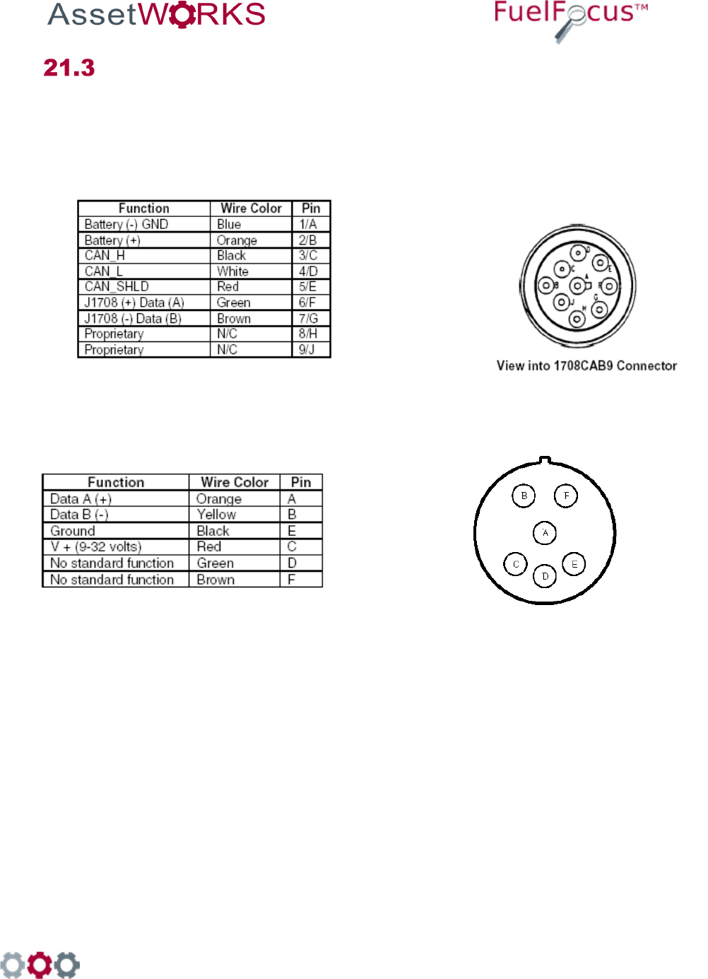
998 Old Eagle School Road, Suite 1215 | Wayne, Pennsylvania 19087 | T: 610-225-8350 | F: 610.971.9447 | www.assetworks.com
92
Appendix C: J1708 Data Connectors
21.3.1 SAE J1708 Data Interface Cables
Option 1: SAE J1708 Model 1708CAB9
Figure 22: SAE J1708 Model 1708CAB9
Option 2: SAE J1708 Model 1708CAB
Figure 23: SAE J1708 Model 1708CAB
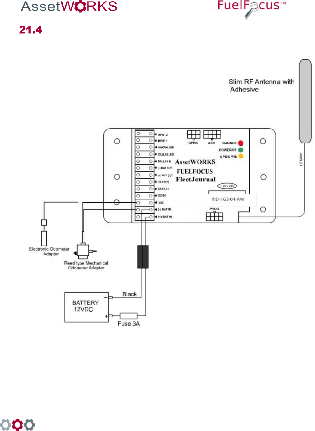
998 Old Eagle School Road, Suite 1215 | Wayne, Pennsylvania 19087 | T: 610-225-8350 | F: 610.971.9447 | www.assetworks.com
93
Appendix D: Wiring for Speed Pulse
21.4.1 Speed Pulse Wiring
Figure 24 Wiring Diagram for Speed Pulse
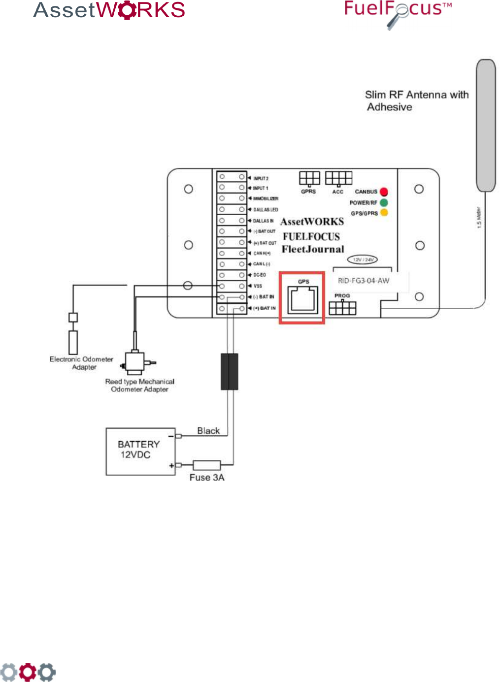
998 Old Eagle School Road, Suite 1215 | Wayne, Pennsylvania 19087 | T: 610-225-8350 | F: 610.971.9447 | www.assetworks.com
94
21.4.2 Speed Pulse Wiring with Passive GPS
Figure 25 Wiring Diagram for Speed Pulse with Passive GPS
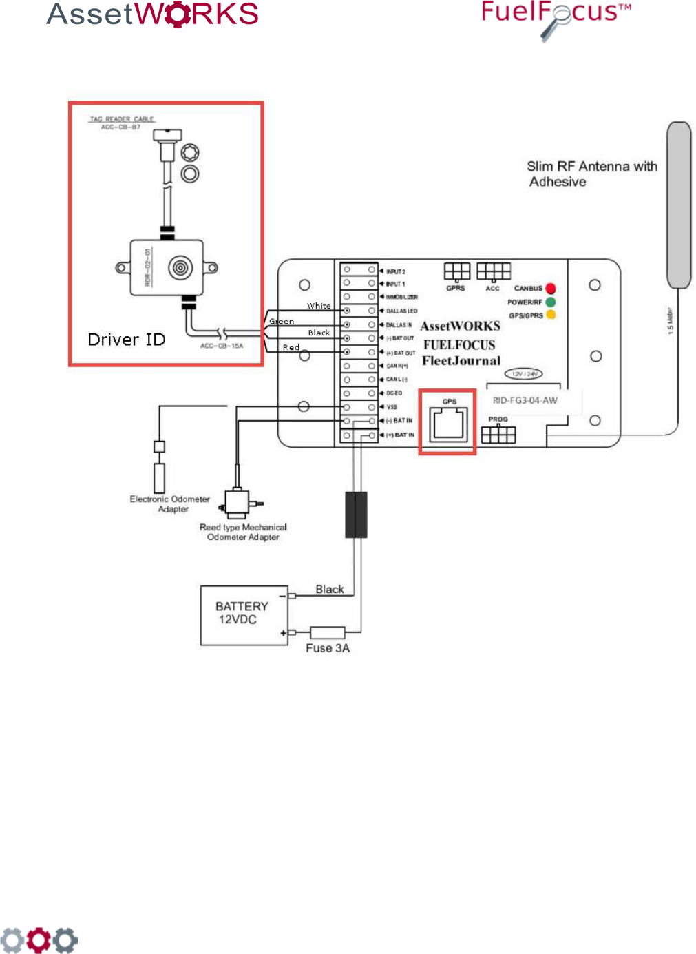
998 Old Eagle School Road, Suite 1215 | Wayne, Pennsylvania 19087 | T: 610-225-8350 | F: 610.971.9447 | www.assetworks.com
95
21.4.3 Speed Pulse Wiring with Passive GPS and Driver ID
Figure 26 Wiring Diagram for Speed Pulse with Passive GPS and Driver ID
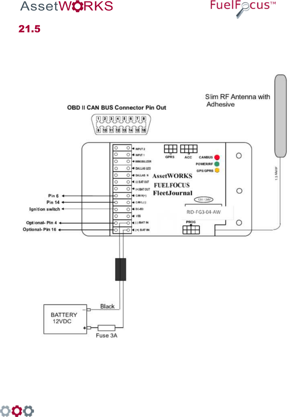
998 Old Eagle School Road, Suite 1215 | Wayne, Pennsylvania 19087 | T: 610-225-8350 | F: 610.971.9447 | www.assetworks.com
96
Appendix E: Wiring the CAN Bus for Light Duty
Vehicles
21.5.1 CAN Bus: Light Duty Vehicles
Figure 27 Wiring for the CAN Bus Interface for Light Duty Vehicles
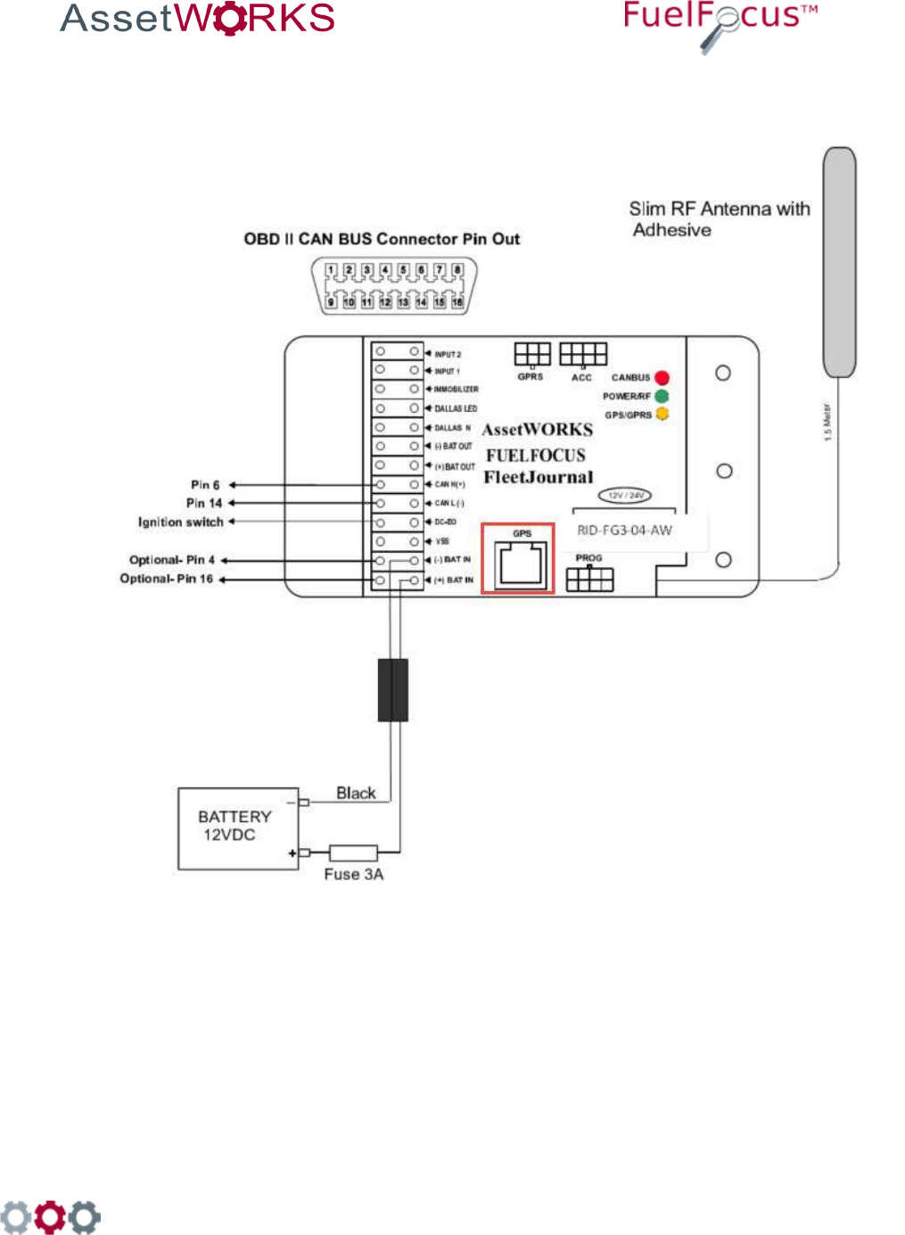
998 Old Eagle School Road, Suite 1215 | Wayne, Pennsylvania 19087 | T: 610-225-8350 | F: 610.971.9447 | www.assetworks.com
97
21.5.2 CAN Bus: Light Duty with Passive GPS
Figure 28 Wiring for the CAN Bus Interface for Light Duty Vehicles with Passive GPS
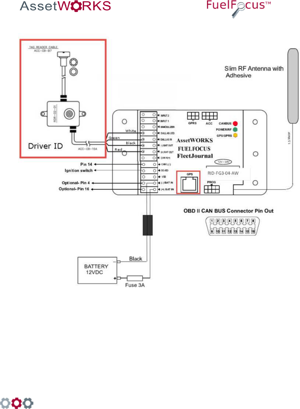
998 Old Eagle School Road, Suite 1215 | Wayne, Pennsylvania 19087 | T: 610-225-8350 | F: 610.971.9447 | www.assetworks.com
98
21.5.3 CAN Bus: Light Duty with Passive GPS and Driver ID
Figure 29 Wiring for CAN Bus Interface for Light Duty Vehicles with Passive GPS and Driver ID
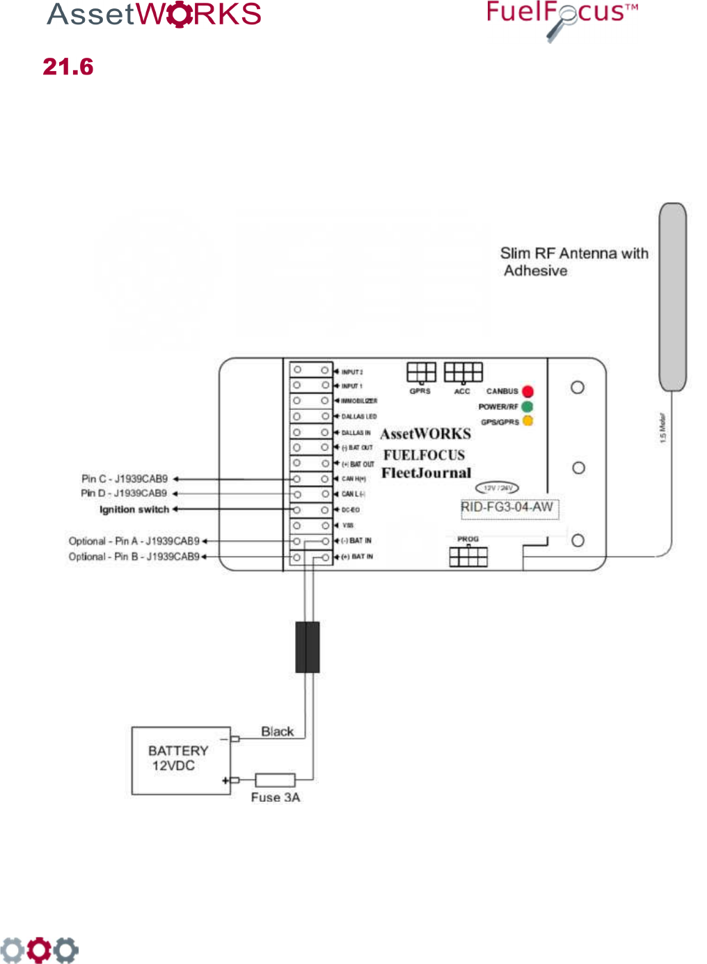
998 Old Eagle School Road, Suite 1215 | Wayne, Pennsylvania 19087 | T: 610-225-8350 | F: 610.971.9447 | www.assetworks.com
99
Appendix F: Wiring the CAN Bus for Heavy Duty
Vehicles
21.6.1 CAN Bus: Heavy Duty Vehicles
21.6.1.1 CAN Bus Heavy Duty Vehicles with SAEJ1939 Connector
Figure 30 Wiring for CAN Bus Heavy Duty Vehicles with SAEJ1939 Connector
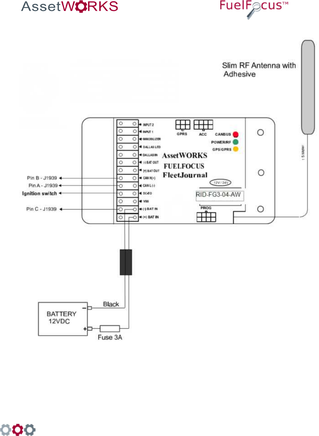
998 Old Eagle School Road, Suite 1215 | Wayne, Pennsylvania 19087 | T: 610-225-8350 | F: 610.971.9447 | www.assetworks.com
100
21.6.1.2 CAN Bus Heavy Duty Vehicles with [Triangular] 3-pin Deutsch Connector
Figure 31 Wiring for the CAN Bus Heavy Duty Vehicles with [Triangular] 3-pin Deutsch Connector
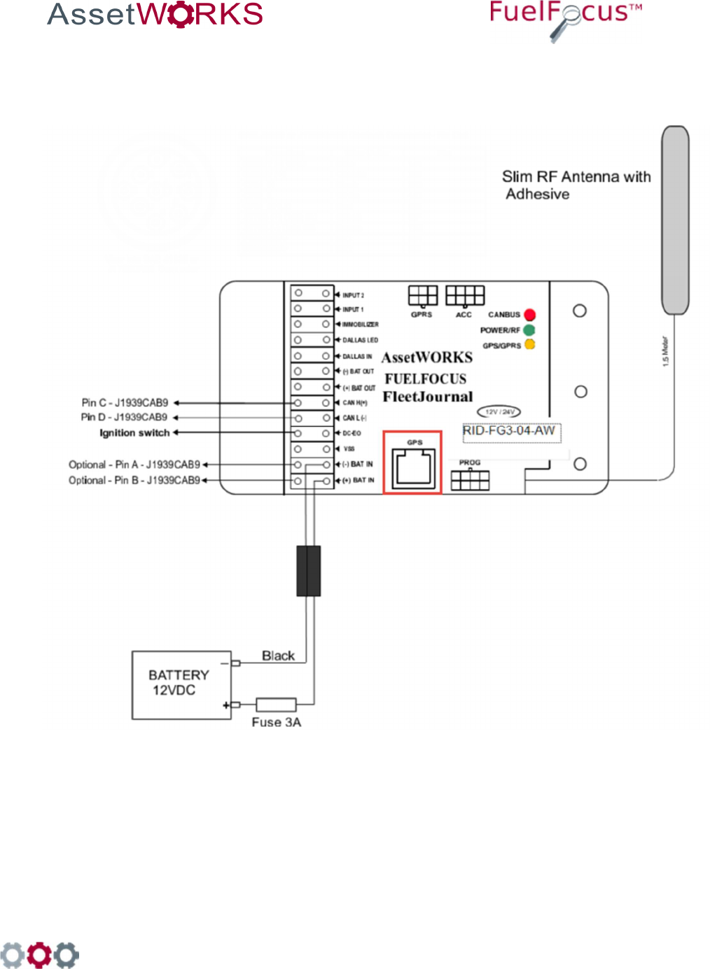
998 Old Eagle School Road, Suite 1215 | Wayne, Pennsylvania 19087 | T: 610-225-8350 | F: 610.971.9447 | www.assetworks.com
101
21.6.2 CAN Bus: Heavy Weight with Passive GPS
21.6.2.1 CAN Bus Heavy Duty Vehicles with SAEJ1939 Connector with Passive GPS
Figure 32 Wiring for CAN Bus Heavy Duty Vehicles with SAEJ1939 Connector and Passive GPS
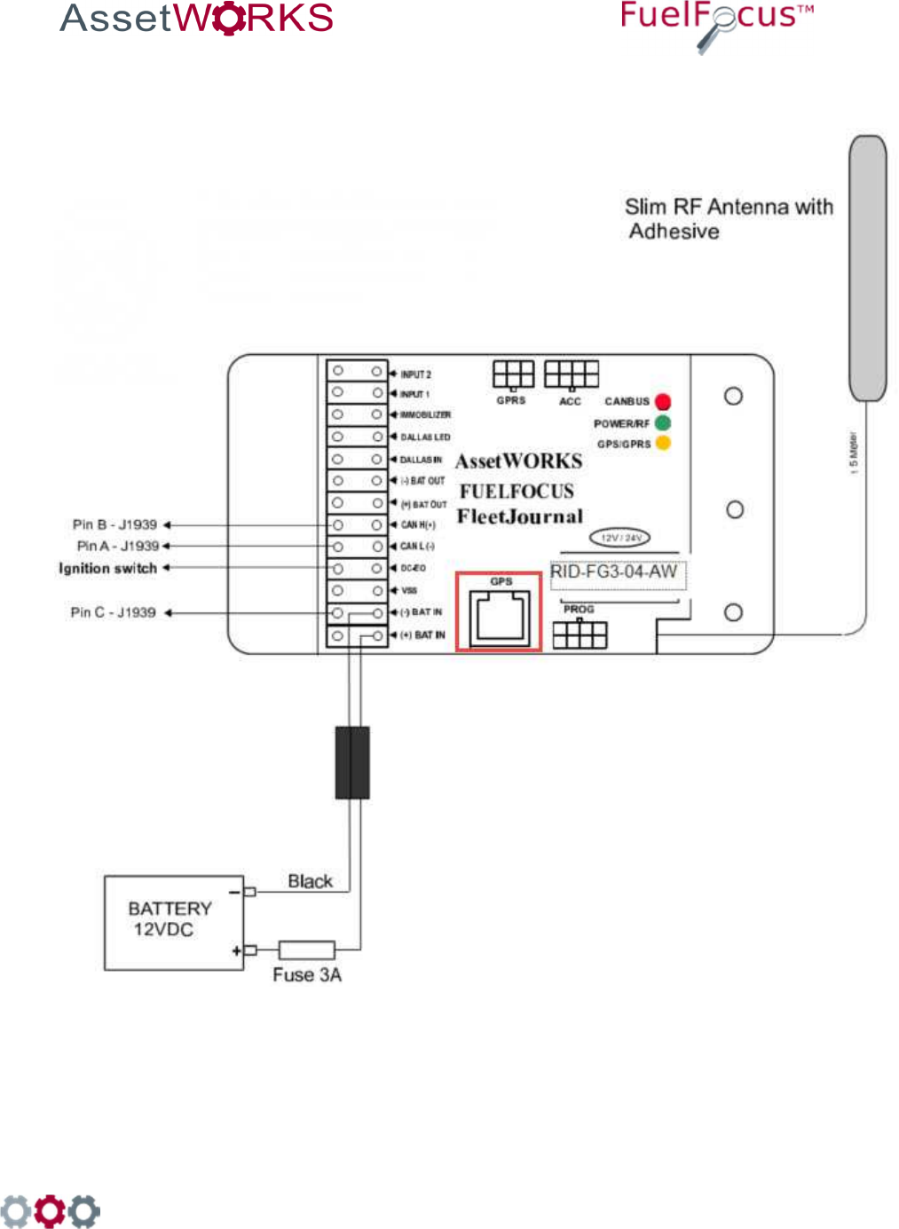
998 Old Eagle School Road, Suite 1215 | Wayne, Pennsylvania 19087 | T: 610-225-8350 | F: 610.971.9447 | www.assetworks.com
102
21.6.2.2 CAN Bus Heavy Duty Vehicles with [Triangular] 3-pin Deutsch Connector with
Passive GPS
Figure 33 Wiring for the CAN Bus Heavy Duty Vehicles with [Triangular] 3-pin Deutsch Connector with
Passive GPS
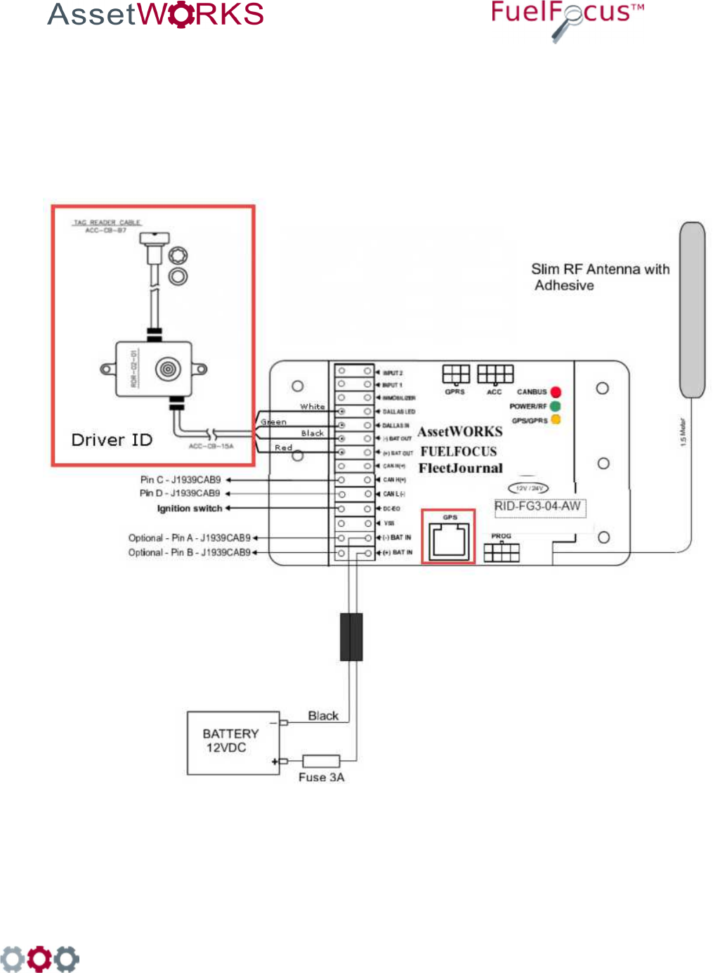
998 Old Eagle School Road, Suite 1215 | Wayne, Pennsylvania 19087 | T: 610-225-8350 | F: 610.971.9447 | www.assetworks.com
103
21.6.3 CAN Bus: Heavy Weight with Passive GPS and Driver ID
21.6.3.1 CAN Bus Heavy Duty Vehicles with SAEJ1939 Connector with Passive GPS and
Driver ID
Figure 34 Wiring for CAN Bus Heavy Duty Vehicles with SAEJ1939 Connector with Passive GPS and
Driver ID
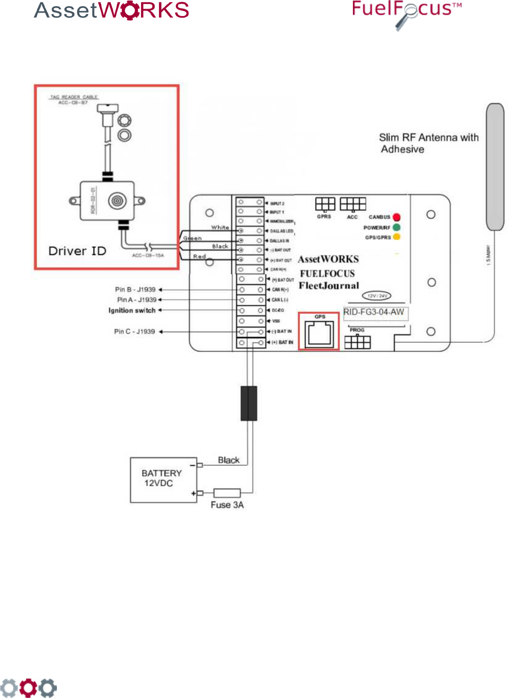
998 Old Eagle School Road, Suite 1215 | Wayne, Pennsylvania 19087 | T: 610-225-8350 | F: 610.971.9447 | www.assetworks.com
104
21.6.3.2 CAN Bus Heavy Duty Vehicles with [Triangular] 3-pin Deutsch Connector with
Passive GPS and Driver ID
Figure 35 Wiring for the CAN Bus Heavy Duty Vehicles with [Triangular] 3-pin Deutsch Connector
with Passive GPS and Driver ID
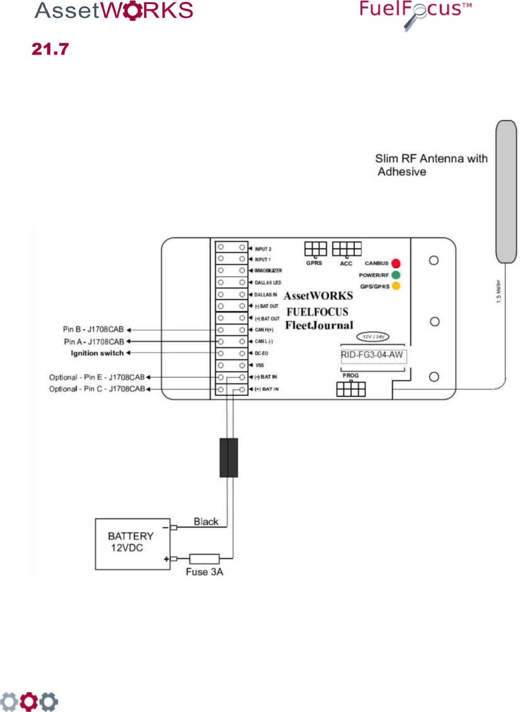
998 Old Eagle School Road, Suite 1215 | Wayne, Pennsylvania 19087 | T: 610-225-8350 | F: 610.971.9447 | www.assetworks.com
105
Appendix G: Wiring the J1708CAB [6-pin]
Connector
21.7.1 Wiring for the J1708CAB [6-pin] Connector
Figure 36 Wiring for the J1708CAB [6-pin] Connector
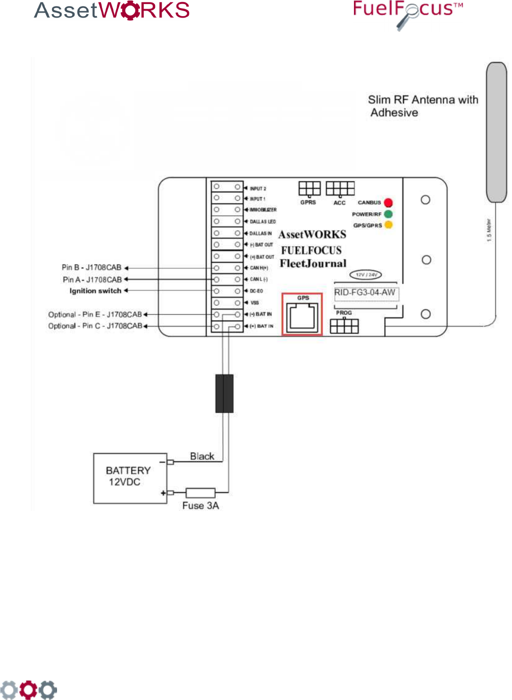
998 Old Eagle School Road, Suite 1215 | Wayne, Pennsylvania 19087 | T: 610-225-8350 | F: 610.971.9447 | www.assetworks.com
106
21.7.2 Wiring for the J1708CAB [6-pin] Connector with Passive GPS
Figure 37 Wiring for the J1708CAB [6-pin] Connector with Passive GPS
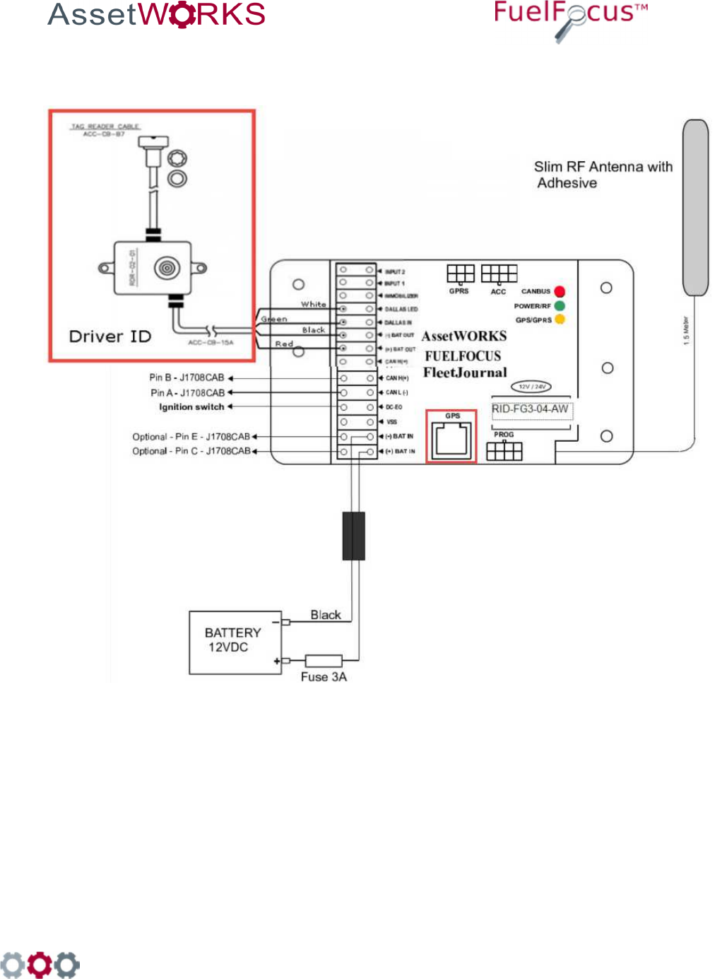
998 Old Eagle School Road, Suite 1215 | Wayne, Pennsylvania 19087 | T: 610-225-8350 | F: 610.971.9447 | www.assetworks.com
107
21.7.3 Wiring for the J1708CAB [6-pin] Connector with Passive GPS
and Driver ID
Figure 38 Wiring for the J1708CAB [6-pin] Connector with Passive GPS and Driver ID
998 Old Eagle School Road, Suite 1215 | Wayne, Pennsylvania 19087 | T: 610-225-8350 | F: 610.971.9447 | www.assetworks.com
108
Appendix H: The FCC Wants You to Know
This equipment has been tested and found to comply with the limits for a Class B digital
device, pursuant to Part 15 of the FCC rules. These limits are designed to provide reasonable
protection against harmful interference in a residential installation. This equipment generates
uses and can radiate radio frequency energy and, if the equipment not installed and used in
accordance with the instructions, may cause harmful interference to radio communications.
However, there is no guarantee that interference will not occur in a particular installation. If this
equipment does cause harmful interference to radio or television reception, which can be
determined by turning the equipment off and on, the user is encouraged to try to correct the
interference by one or more of the following measures:
a) Reorient or relocate the receiving antenna.
b) Increase the separation between the equipment and receiver.
c) Connect the equipment to an outlet on a circuit different from that to which the
receiver is connected.
d) Consult the dealer or an experienced radio/TV technician.
FCC Warning
Modifications not expressly approved by the manufacturer could void the user authority to
operate the equipment under FCC Rules.
This device complies with Part 15 of the FCC Rules. Operation is subject to the following two
conditions:
(1) This device may not cause harmful interference.
(2) This device must accept any interference received, including interference
that may cause undesired operation.