Rosemount Aerospace 8730L1-5 Aircraft interface device User Manual
Rosemount Aerospace Inc. Aircraft interface device
Contents
- 1. User manual
- 2. user manual
user manual

Rosemount Aerospace Inc.
14300 Judicial Road
Burnsville, MN 55306-4898
Tel: 952 892 4000
Fax: 952 892 4800
www.utcaerospacesystems.com
Page 1 of 13
THIS DOCUMENT IS THE PROPERTY OF UTC AEROSPACE SYSTEMS. YOU MAY NOT POSSESS, USE, COPY OR DISCLOSE THIS DOCUMENT OR ANY
INFORMATION IN IT, FOR ANY PURPOSE, INCLUDING WITHOUT LIMITATION, TO DESIGN, MANUFACTURE OR REPAIR PARTS, OR OBTAIN ANY
GOVERNMENT APPROVAL TO DO SO, WITHOUT UTC AEROSPACE SYSTEMS’S EXPRESS WRITTEN PERMISSION. NEITHER RECEIPT NOR
POSSESSION OF THIS DOCUMENT ALONE, FROM ANY SOURCE, CONSTITUTES SUCH PERMISSION.POSSESSION, USE, COPYING OR DISCLOSURE
BY ANYONE WITHOUT UTC AEROSPACE SYSTEMS’S EXPRESS WRITTEN PERMISSION IS NOT AUTHORIZED AND MAY RESULT IN CRIMINAL AND/OR
CIVIL LIABILITY.
USER MANUAL
Aircraft Interface Device
Rosemount Aerospace Inc. Model 8730L Series
Document Number D06429976 Revision 06
Controlled electronic approvals are on file and available for review:
Reference Change Order #: SISMN067934
Prepared by
Jeffery Paatela
Design Engineer
3 NOV 2016
Prepared and
Approved by
Ryan Kollman
Design Engineer
NOTE:
References to the company in this document will be made as Rosemount Aerospace Inc. (RMTAERO).
U.S. Export Classification: EAR: 7E994
By Sandee Pomplun at 12:19 pm, Nov 07, 2016
USER MANUAL — Aircraft Interface Device
Page 2 of 13
Rosemount Aerospace Inc. Model 8730L Series
D06429976 Revision 06
UTC AEROSPACE SYSTEMS PROPRIETARY
SUBJECT TO THE RESTRICTION ON THE TITLE OR COVER PAGE.
U.S. Export Classification: EAR: 7E994
Revision History
Revision
Section
Change Description
CO Number
02
All
Initial release
SISMN059487
03
2.1
Updated model information
SISMN061700
3.3.4
Updated approval information
04
2.5
Updated antenna recommendations with gain limits
SISMN064413
3.3.3
Added instructions for retrieving R&TTE DoC
All
Formatting updates
05
2.2
Added statement on device mounting
SISMN066356
2.5
Updated antenna info
Table 2
Updated radio information
06
2.5
Updated antenna info
SISMN067934

USER MANUAL — Aircraft Interface Device
Page 3 of 13
Rosemount Aerospace Inc. Model 8730L Series
D06429976 Revision 06
UTC AEROSPACE SYSTEMS PROPRIETARY
SUBJECT TO THE RESTRICTION ON THE TITLE OR COVER PAGE.
U.S. Export Classification: EAR: 7E994
Table of Contents
1 ABOUT THIS DOCUMENT 5
1.1 Purpose .................................................................................................................................................................. 5
1.2 Applicable Documents ............................................................................................................................................ 5
1.3 Abbreviations and Acronyms .................................................................................................................................. 6
1.4 Terms and Definitions ............................................................................................................................................. 7
2 AIRCRAFT INTERFACE DEVICE (AID) 8
2.1 AID Overview .......................................................................................................................................................... 8
2.2 Mechanical Interfaces ............................................................................................................................................. 9
2.3 Electrical Interfaces................................................................................................................................................. 9
2.4 Power Requirements ............................................................................................................................................ 10
2.5 Wireless Antenna Recommendations ................................................................................................................... 10
3 CERTIFICATIONS 11
3.1 DO-160 ................................................................................................................................................................. 11
3.2 DO-254 and DO-178C .......................................................................................................................................... 12
3.3 Wireless Regulatory Compliance And Industry Certification ................................................................................. 12
3.3.1 FCC ............................................................................................................................................................. 12
3.3.2 Industry Canada........................................................................................................................................... 12
3.3.3 CE ................................................................................................................................................................ 13
3.3.4 PTCRB ......................................................................................................................................................... 13

USER MANUAL — Aircraft Interface Device
Page 4 of 13
Rosemount Aerospace Inc. Model 8730L Series
D06429976 Revision 06
UTC AEROSPACE SYSTEMS PROPRIETARY
SUBJECT TO THE RESTRICTION ON THE TITLE OR COVER PAGE.
U.S. Export Classification: EAR: 7E994
List of Tables
Table 1: Applicable Documents .................................................................................................................................. 5
Table 2: Model Configurations .................................................................................................................................... 9
Table 3: Power Supply.............................................................................................................................................. 10
List of Figures
Figure 1: 8730L Series AID ........................................................................................................................................ 8
USER MANUAL — Aircraft Interface Device
Page 5 of 13
Rosemount Aerospace Inc. Model 8730L Series
D06429976 Revision 06
UTC AEROSPACE SYSTEMS PROPRIETARY
SUBJECT TO THE RESTRICTION ON THE TITLE OR COVER PAGE.
U.S. Export Classification: EAR: 7E994
1 ABOUT THIS DOCUMENT
The 8730L Series Aircraft Interface Device (AID) provides an interface between various aircraft avionics systems
and nontraditional avionics equipment such as Electronic Flight Bags (EFB), In-Flight Entertainment (IFE)
Systems, broadband communications systems (cellular, Wi-Fi) or onboard network servers; providing both a
hardware and software firewall protecting the critical aircraft systems against any adverse effect from the
interfacing nontraditional equipment.
The AID incorporates a variety of industry standard interfaces; including Ethernet, ARINC 429, ARINC 717, RS-
232, RS-422/485, USB, and Discrete inputs/outputs. The AID also provides a removable mass data storage
device enabling local data storage to hosted applications. An optional embedded cellular or Wi-Fi radio using
remote antennas is available.
The AID incorporates a Linux operating system running on a PowerPC based micro-processor utilizing DDR3
memory. Software supports avionics interface data reception, transmission, concentration, and recording. Access
to this data is provided to locally hosted or remote equipment applications via a built-in ARINC 834 server.
1.1 Purpose
This Users Manual provides an overall guide to the 8730L AID.
1.2 Applicable Documents
The following specifications, drawings, and publications, of latest issue when not specified, form a part of this
document to the extent specified herein.
Table 1: Applicable Documents
Rosemount Aerospace Inc.
Document No.
Document Title
8730L1
Specification Control Drawing for the AID
Industry Standards
Document No.
Document Title
ARINC 429
Aircraft Mark 33 Digital Information Transfer System
ARINC 664
Aircraft Data Network
ARINC 717
Flight Data Acquisition and Recording System
ANSI/TIA/EIA-232-B
Interface between data terminal equipment and data circuit terminating equipment
ANSI/TIA/EIA-422-B
Electrical Characteristics of balanced digital interface circuits
ANSI/TIA/EIA-485-B
Electrical characteristics of generators and receivers for use in balanced digital multiport systems

USER MANUAL — Aircraft Interface Device
Page 6 of 13
Rosemount Aerospace Inc. Model 8730L Series
D06429976 Revision 06
UTC AEROSPACE SYSTEMS PROPRIETARY
SUBJECT TO THE RESTRICTION ON THE TITLE OR COVER PAGE.
U.S. Export Classification: EAR: 7E994
1.3 Abbreviations and Acronyms
AID
Aircraft Interface Device
ARINC
Aeronautical Radio Incorporated
DDR3
Double Data Rate type 3 Synchronous
Dynamic Random Access Memory
DoC
Declaration of Conformity
EFB
Electronic Flight Bag
ICD
Interface Control Document
IFE
In-Flight Entertainment
lbs
pounds
SIM
Subscriber Identity Module
USB
Universal Serial Bus
VDC
Voltage - direct current

USER MANUAL — Aircraft Interface Device
Page 7 of 13
Rosemount Aerospace Inc. Model 8730L Series
D06429976 Revision 06
UTC AEROSPACE SYSTEMS PROPRIETARY
SUBJECT TO THE RESTRICTION ON THE TITLE OR COVER PAGE.
U.S. Export Classification: EAR: 7E994
1.4 Terms and Definitions
Qualification — Demonstrates that the implementation meets the requirements and is suitable for operation in the airplane.
Shall — Expresses a binding requirement.
Should/May — Expresses a recommended or allowed action.
Validation — Identifies that the requirements for a product are sufficiently correct and complete.
Verification — Identifies that the implementation has been evaluated to determine that all design requirements have been
met.
Will — Expresses a declaration of intent.
USER MANUAL — Aircraft Interface Device
Page 8 of 13
Rosemount Aerospace Inc. Model 8730L Series
D06429976 Revision 06
UTC AEROSPACE SYSTEMS PROPRIETARY
SUBJECT TO THE RESTRICTION ON THE TITLE OR COVER PAGE.
U.S. Export Classification: EAR: 7E994
2 AIRCRAFT INTERFACE DEVICE (AID)
2.1 AID Overview
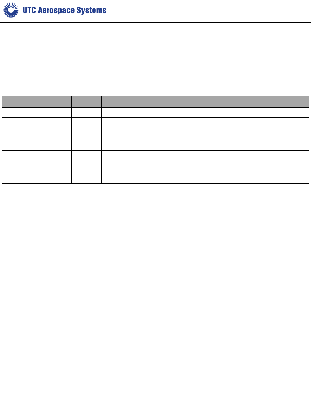
The 8730L AID has the following external features as shown in Figure 1:
J1, 37-pin D-sub connector providing interfaces to the following: Aircraft +28V power, Chassis Ground,
ARINC 664 Ethernet 10/100 Base T, ARINC 717 Harvard Bi-Phase receiver, ARINC 429 Bipolar receivers,
ARINC 429 Bipolar transmitters, RS-232, and discrete inputs
J2, 37-pin D-sub connector providing interfaces to the following: ARINC 664 Ethernet 10/100/1000 Base T,
ARINC 429 receivers, ARINC 429/717 Bipolar receiver, ARINC 429 Bipolar transmitters, and discrete inputs
J3, 50-pin D-sub connector providing interfaces to the following: ARINC 664 Ethernet 10/100/1000 Base T,
ARINC 429 receivers, ARINC 429/717 Bipolar receiver, ARINC 429 Bipolar transmitters, RS-422/485, USB,
discrete inputs, and discrete outputs
Access Cover for removable CFast Storage device and SIM card (SIM card supports cellular capability).
Three (3) external antenna connectors (for Wi-Fi or cellular capability)
Mounting provisions
Weight: 2.5 lbs max for base unit, add 0.2 lbs for each cellular and/or Wi-Fi, add 0.1 lbs for CFast, add 0.15
lbs for 8730L1-5 model.
Overall View
Front View Back View
Figure 1: 8730L Series AID
Electrical
Connectors
Wi-Fi antenna
cable connector
Cellular antenna
cable connectors
SIM and CFast
Access Cover
Mounting
Provisions
USER MANUAL — Aircraft Interface Device
Page 9 of 13
Rosemount Aerospace Inc. Model 8730L Series
D06429976 Revision 06
UTC AEROSPACE SYSTEMS PROPRIETARY
SUBJECT TO THE RESTRICTION ON THE TITLE OR COVER PAGE.
U.S. Export Classification: EAR: 7E994
There are five defined model configurations of the AID, each supporting different wireless needs. Model
configuration is accomplished during factory build through the installation radio module internal to the AID
enclosure.
NOTE:
The radios are not accessible and should not be removed by the User.
Table 2: Model Configurations
Manufacturer
Model
Wireless Communications
Radio Module
UTC Aerospace Systems
8730L1-1
No Wireless (Base model)
None
UTC Aerospace Systems
8730L1-2
Cellular
(LTE in North America; 2G/3G elsewhere)
Sierra Wireless MC7354
UTC Aerospace Systems
8730L1-3
Cellular
(LTE in Europe, Middle East, Africa; 2G/3G elsewhere)
Sierra Wireless MC7304
UTC Aerospace Systems
8730L1-4
Wi-Fi (802.11 a/b/g/n)
Advantech EWM-W158F
UTC Aerospace Systems
8730L1-5
Cellular (LTE in North America and EMEA) and Wi-Fi
(802.11 b/g/n)
Sierra Wireless MC7455
and SparkLAN WUBA-
171GN
A SIM card can be installed or removed through the Access Cover on the back of the AID.
The AID has the capability to allow the user to install a CFast card; a solid-state non-volatile data storage device.
The CFast card is a separate LRU (not part of the standard AID configuration) and is accessible through the
Access Cover on the back of the AID for easy removal or insertion. CFast model number 8732D1-1 is available
from UTC Aerospace Systems and has been qualified to operate within the AID operating environment.
NOTE:
The CFast and SIM card are not considered to be hot-pluggable. Ensure the AID is powered off prior to inserting
or removing these devices from the AID.
NOTE:
If the Access Cover on the back of the AID is removed for any reason, reinstall the cover prior to using the AID in
its intended function.
2.2 Mechanical Interfaces
The AID provides mounting provisions (or holes) on the sides of the unit as shown in Figure 1. The 8730L AID is
mounted in the aircraft as a fixed device; it is not movable by the user. The mounting provisions are designed to
interface with a simple U-bracket mounting provision with holes for screws or captive fasteners on the two sides.
Two L-brackets are another potentially simple solution, one on each side.
The AID is cooled by natural convection and by conduction through the mounting provisions. Sufficient clearance
must be provided to permit air flow in the installation. The installation should also be designed to provide a path
for heat to flow through the mounting bracket into the structure.
2.3 Electrical Interfaces
The AID electrical interfaces are made through one 37-pin D-sub pins, (J1), one 37-pin D-sub socket, (J2), and
one 50-pin D-sub pins (J3). The Wi-Fi antenna cable connection and the cellular antenna cable connections are
made with SMA connectors.
USER MANUAL — Aircraft Interface Device
Page 10 of 13
Rosemount Aerospace Inc. Model 8730L Series
D06429976 Revision 06
UTC AEROSPACE SYSTEMS PROPRIETARY
SUBJECT TO THE RESTRICTION ON THE TITLE OR COVER PAGE.
U.S. Export Classification: EAR: 7E994
The AID provides a chassis ground electrical bonding path through a metal surface contact around its mounting
holes. In addition, the AID bonds its connector shells to local chassis ground and provides a chassis ground pin
in connector J1. One or more of these points should be connected to the aircraft chassis ground through a low
impedance connection path.
2.4 Power Requirements
The AID requires 28 VDC aircraft power as defined in Table 3. Circuit breakers should be chosen based on max
current as shown.
Table 3: Power Supply
Power Characteristic
Value
Voltage
+28 VDC nominal (18 VDC – 32.2 VDC range)
Current (typical)
0.71A @ 28VDC
Current (max continuous)
0.9A @ 28VDC
Inrush Current (max)
6A @ 28VDC (<100ms)
Power Consumption (typical idle)
20W
Power Consumption (max continuous)
25W
2.5 Wireless Antenna Recommendations
Attached cellular antennas should be Laird part number DBA6927C1-xxxxx. Alternate antennas with similar
performance may be suitable. Gain should not exceed 0.5 dBi at 698-960 MHz and 2.2 dBi at 1710-2700 MHz.
Cellular antennas must be connected through a coaxial cable of at least 20cm length. It is recommended that the
coaxial cable attenuation characteristic is similar or better than Times Microwave Systems Maxgain-200.
Attached Wi-Fi antenna should be Laird part number MAF94271. Alternate antennas with similar performance
may be suitable. Gain should not exceed 2.1 dBi at 2.45 GHz, 2.4 dBi at 4.9 GHz, 2.6 dBi at 5.25 GHz, and 3.4
dBi at 5.875 GHz. The Wi-Fi antenna can be placed directly on the AID, but remote locations through a high
performance coaxial cable may offer improved performance depending on location. Maxgain-200 or better cabling
is recommended.
Guidelines for placement of the antennas:
Antennas should be located in an area with apertures to allow transmission – that is, not a fully enclosed
metal structure.
Maximizing spatial and orthogonal diversity is desired. Locate the antennas not near one another and
rotated 90° relative to one another.
Strive for at least 1 foot away from metal structure.
If a mounting bracket is used to retain the radiating element portion of the antenna(s), it should be non-
metallic and RF-transparent. Avoid carbon based dyes or paint that can hinder RF transmission.
Install antennas in a location where 20 cm is normally maintained between the transmitter’s radiating
structures and the body of nearby persons.
USER MANUAL — Aircraft Interface Device
Page 11 of 13
Rosemount Aerospace Inc. Model 8730L Series
D06429976 Revision 06
UTC AEROSPACE SYSTEMS PROPRIETARY
SUBJECT TO THE RESTRICTION ON THE TITLE OR COVER PAGE.
U.S. Export Classification: EAR: 7E994
3 CERTIFICATIONS
3.1 DO-160
The 8730L AID has been certified to operate within the following environmental conditions.
Test Description
DO-160G
Section
Test Category
Temperature and Altitude
4.5
Operating Low Temp., -40°C, Modified Cat B2
4.5
Operating High Temp., +55°C, Modified Cat B2
4.5
Short-Time Operating Low Temp., -40°C, Modified
Cat B2
4.5
Short-Time Operating High Temp., +70°C, Cat B2
4.5
Ground Survival Low Temp., -55°C, Cat B2
4.5
Ground Survival High Temp., +85°C, Cat B2
4.6.1
Steady State Altitude, 25,000 ft. Cat B2
4.6.2
Decompression, 51,000 ft. Cat A1
4.6.3
Overpressure, 170kPa (-15,000 ft.), Cat A1
Temperature Variation
5
Category B
Humidity
6
Category A Category B
Operational Shocks, Crash Safety
7
6g 11ms Shock Cat B
20g 11ms Crash Safety Impulse Cat B
20g Crash Safety Sustained Cat B
Vibration
8
Category S, Curve C Category U, Curve G
Fluid Susceptibility
11
Category F, as limited to a subset of fluids
Sand and Dust
12
Category S
Fungus Resistance
13
Category F
Magnetic Effect
15
Category Z, less than 0.3 m
Power Input
16
ZXX
Voltage Spike
17
A
Power Supply Audio Frequency Conducted Susceptibility
18
Z
Induced Signal Susceptibility
19
ZC
RF Conducted Susceptibility (10kHz – 400MHz)
20
T
RF Radiated Susceptibility (100MHz – 8GHz)
20
T
RF Conducted Emissions (150kHz – 152MHz)
21
M
RF Radiated Emissions (100MHz – 6GHz)
21
M
Lightning Indirect Effects
22
A1C1X
Electrostatic Discharge
25
A

USER MANUAL — Aircraft Interface Device
Page 12 of 13
Rosemount Aerospace Inc. Model 8730L Series
D06429976 Revision 06
UTC AEROSPACE SYSTEMS PROPRIETARY
SUBJECT TO THE RESTRICTION ON THE TITLE OR COVER PAGE.
U.S. Export Classification: EAR: 7E994
3.2 DO-254 and DO-178C
The AID is developed in accordance with Design Assurance Level E per RTCA/DO-254 and DO-178C.
3.3 Wireless Regulatory Compliance And Industry Certification
The AID has the following regulatory and industry approvals.
3.3.1 FCC
This device complies with Part 15 of the FCC Rules. Operation is subject to the following two conditions: (1) this
device may not cause harmful interference, and (2) this device must accept any interference received, including
interference that may cause undesired operation.
Consult the SCD 8730L1 for model-specific FCC ID numbers.
3.3.2 Industry Canada
This device complies with Industry Canada licence-exempt RSS standard(s). Operation is subject to the following
two conditions:
(1) this device may not cause interference, and
(2) this device must accept any interference, including interference that may cause undesired operation of
the device.
Le présent appareil est conforme aux CNR d'Industrie Canada applicables aux appareils radio exempts de
licence. L'exploitation est autorisée aux deux conditions suivantes :
(1) l'appareil ne doit pas produire de brouillage, et
(2) l'utilisateur de l'appareil doit accepter tout brouillage radioélectrique subi, même si le brouillage est
susceptible d'en compromettre le fonctionnement.
Under Industry Canada regulations, this radio transmitter may only operate using an antenna of a type and
maximum (or lesser) gain approved for the transmitter by Industry Canada. To reduce potential radio interference
to other users, the antenna type and its gain should be so chosen that the equivalent isotropically radiated power
(e.i.r.p.) is not more than that necessary for successful communication.
Conformément à la réglementation d'Industrie Canada, le présent émetteur radio peut fonctionner avec une
antenne d'un type et d'un gain maximal (ou inférieur) approuvé pour l'émetteur par Industrie Canada. Dans le but
de réduire les risques de brouillage radioélectrique à l'intention des autres utilisateurs, il faut choisir le type
d'antenne et son gain de sorte que la puissance isotrope rayonnée équivalente (p.i.r.e.) ne dépasse pas l'intensité
nécessaire à l'établissement d'une communication satisfaisante.
Consult the SCD 8730L1 for model-specific IC ID numbers.
USER MANUAL — Aircraft Interface Device
Page 13 of 13
Rosemount Aerospace Inc. Model 8730L Series
D06429976 Revision 06
UTC AEROSPACE SYSTEMS PROPRIETARY
SUBJECT TO THE RESTRICTION ON THE TITLE OR COVER PAGE.
U.S. Export Classification: EAR: 7E994
3.3.3 CE
This equipment is intended to be used as an Aircraft Interface Device which includes wireless communication.
Hereby, Rosemount Aerospace Inc., declares that this device is in compliance with the essential requirements
and other relevant provisions of Directive 1999/5/EC.
A complete Declaration of Conformity (DoC) is available from UTC Aerospace Systems upon request. Please
contact your Customer Service Representative.
3.3.4 PTCRB
The 8730L1-2 AID is PTCRB certified.
0682