Rosemount Tank Radar 05402 Two-Wire Radar Level Transmitter User Manual Book 5400 RevHA
Rosemount Tank Radar AB Two-Wire Radar Level Transmitter Book 5400 RevHA
UserManual.wiki
>
Rosemount Tank Radar
>
05402 User Manual
User Manual
Navigation menu
Upload a User Manual
Namespaces
Wiki Guide
HTML
PDF
Info
Views
User Manual
Discussion / Help
Navigation

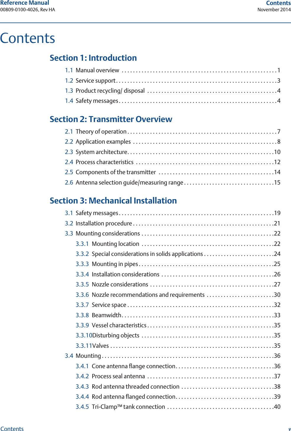
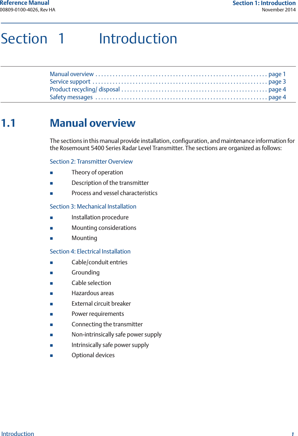
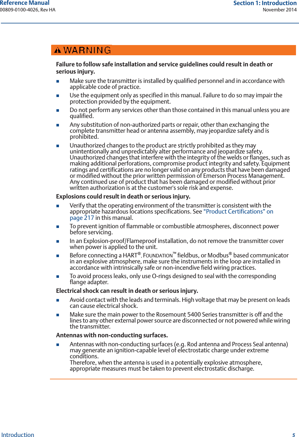

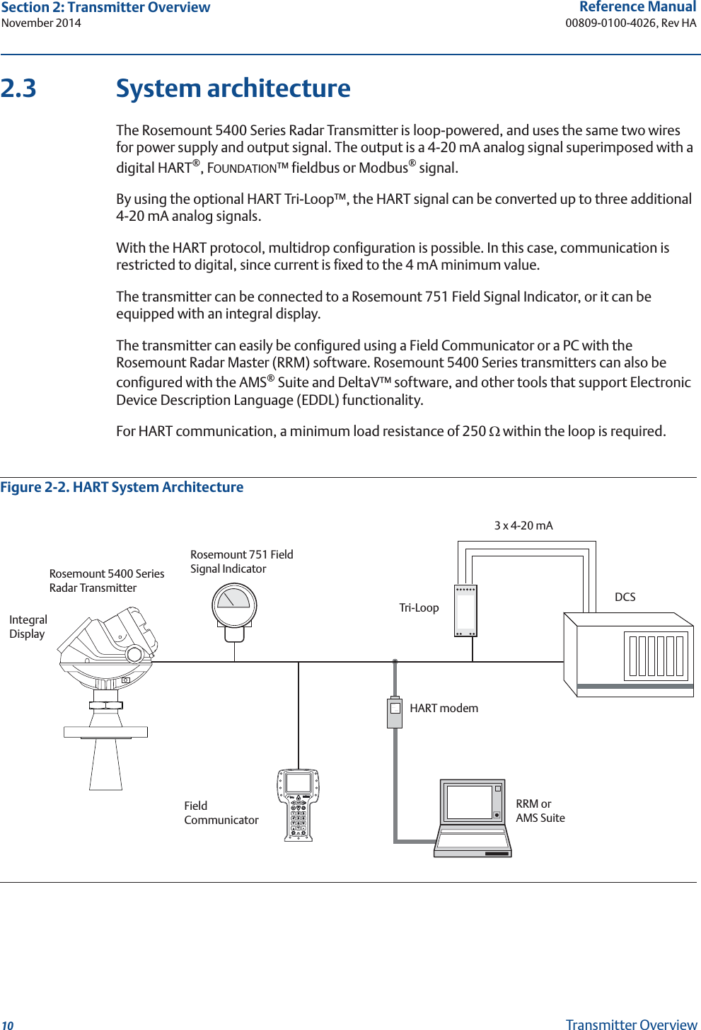
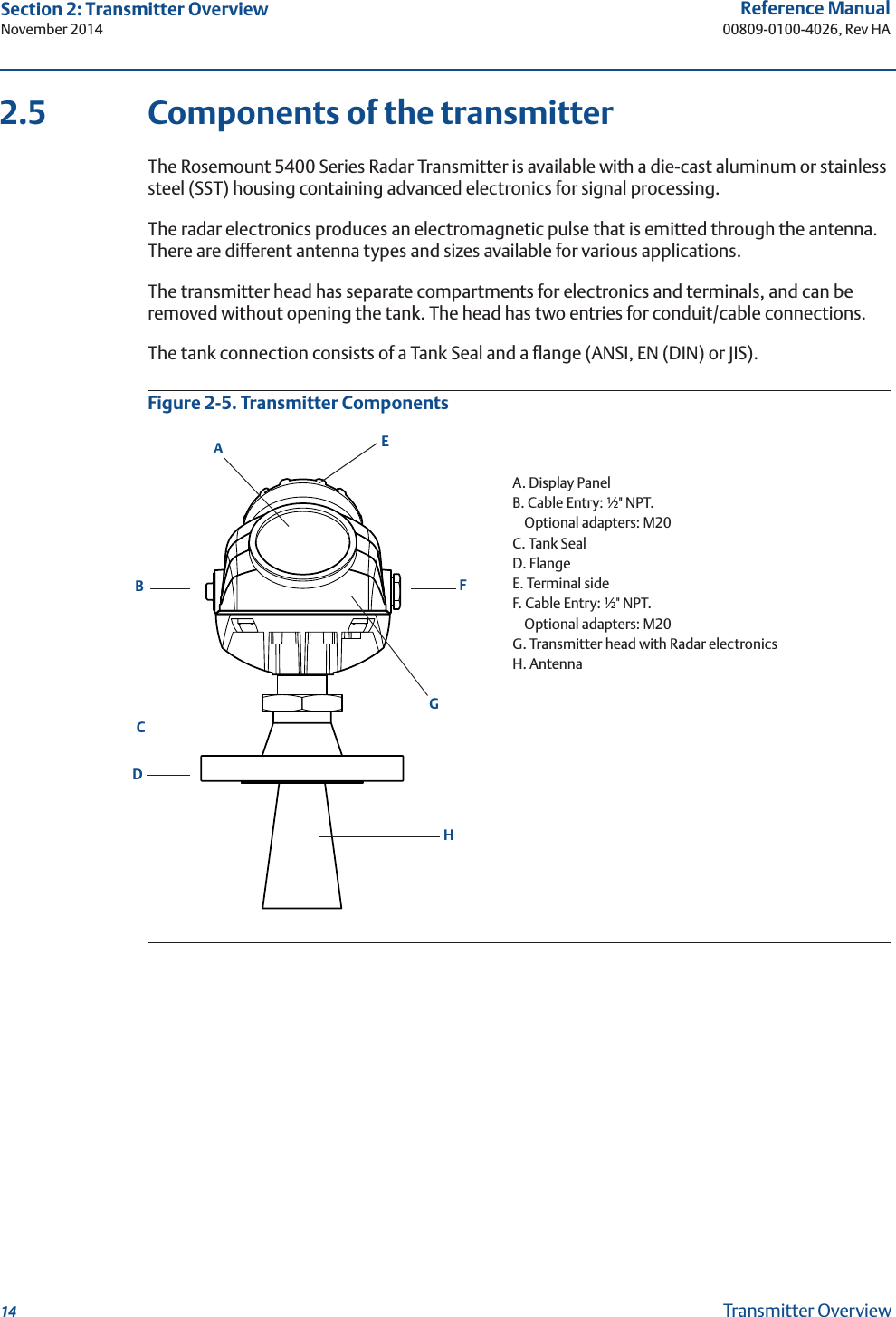

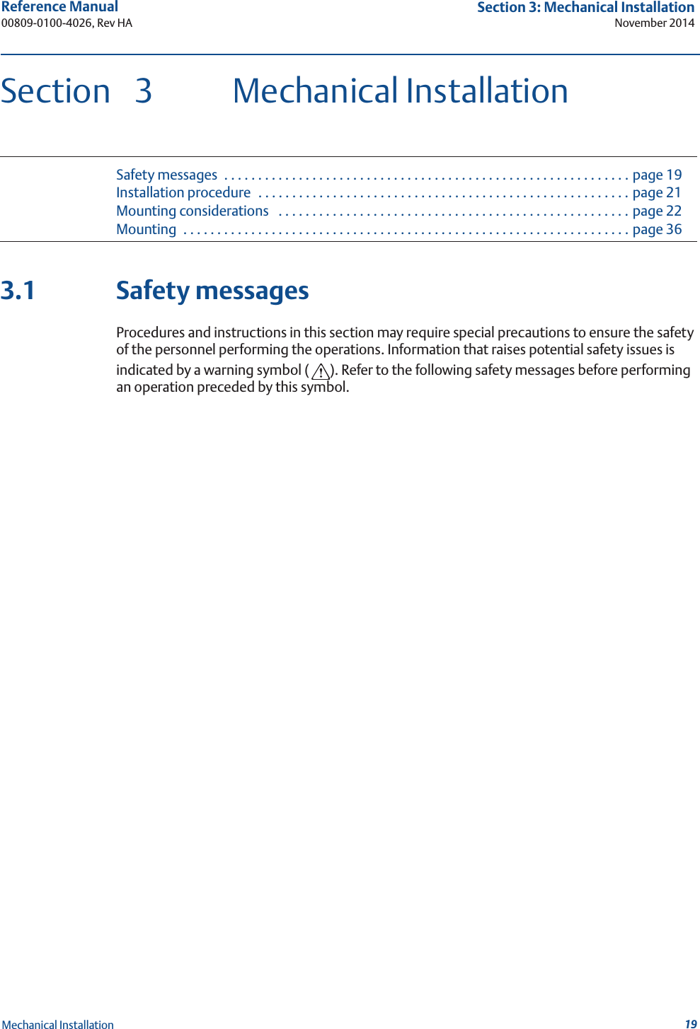
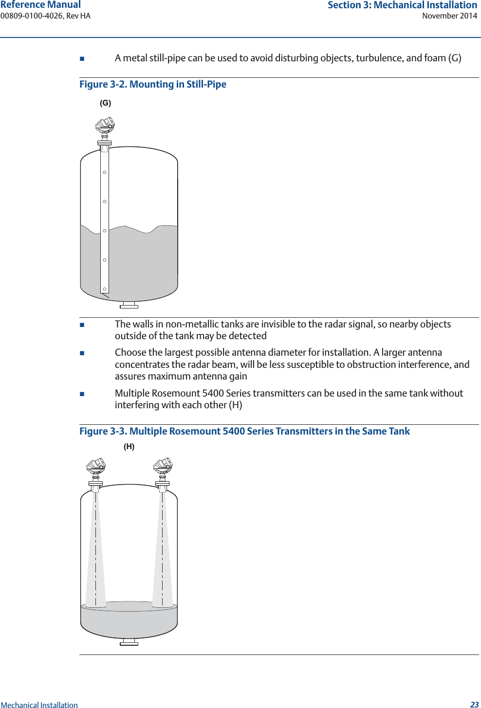
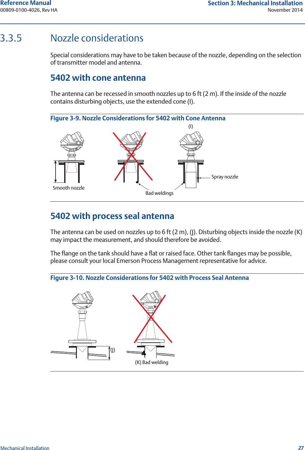
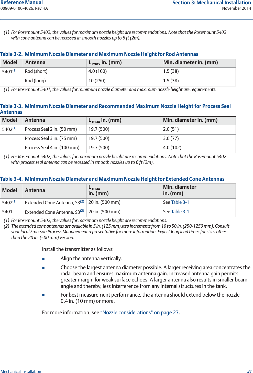
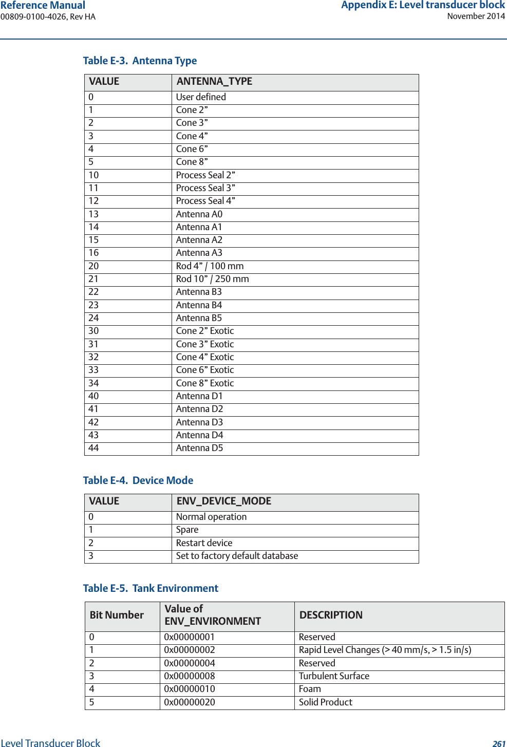
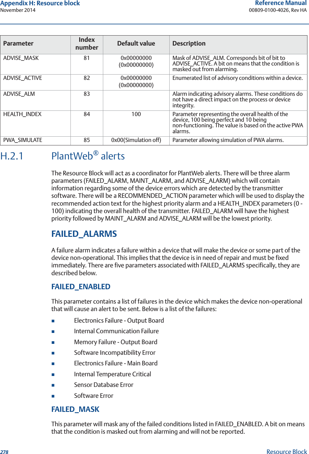
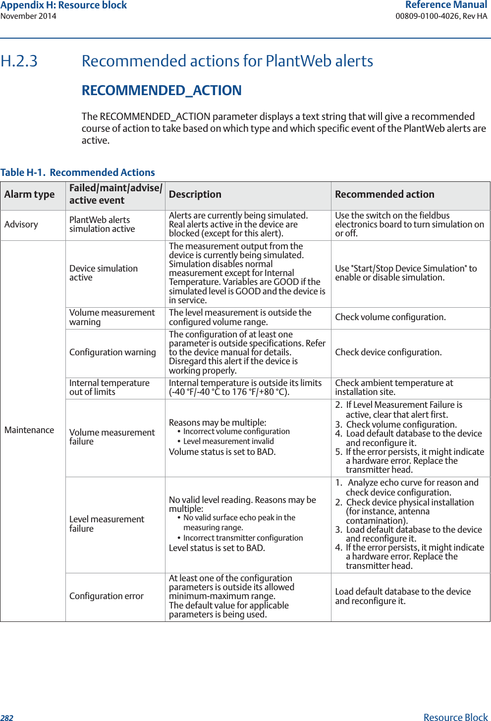
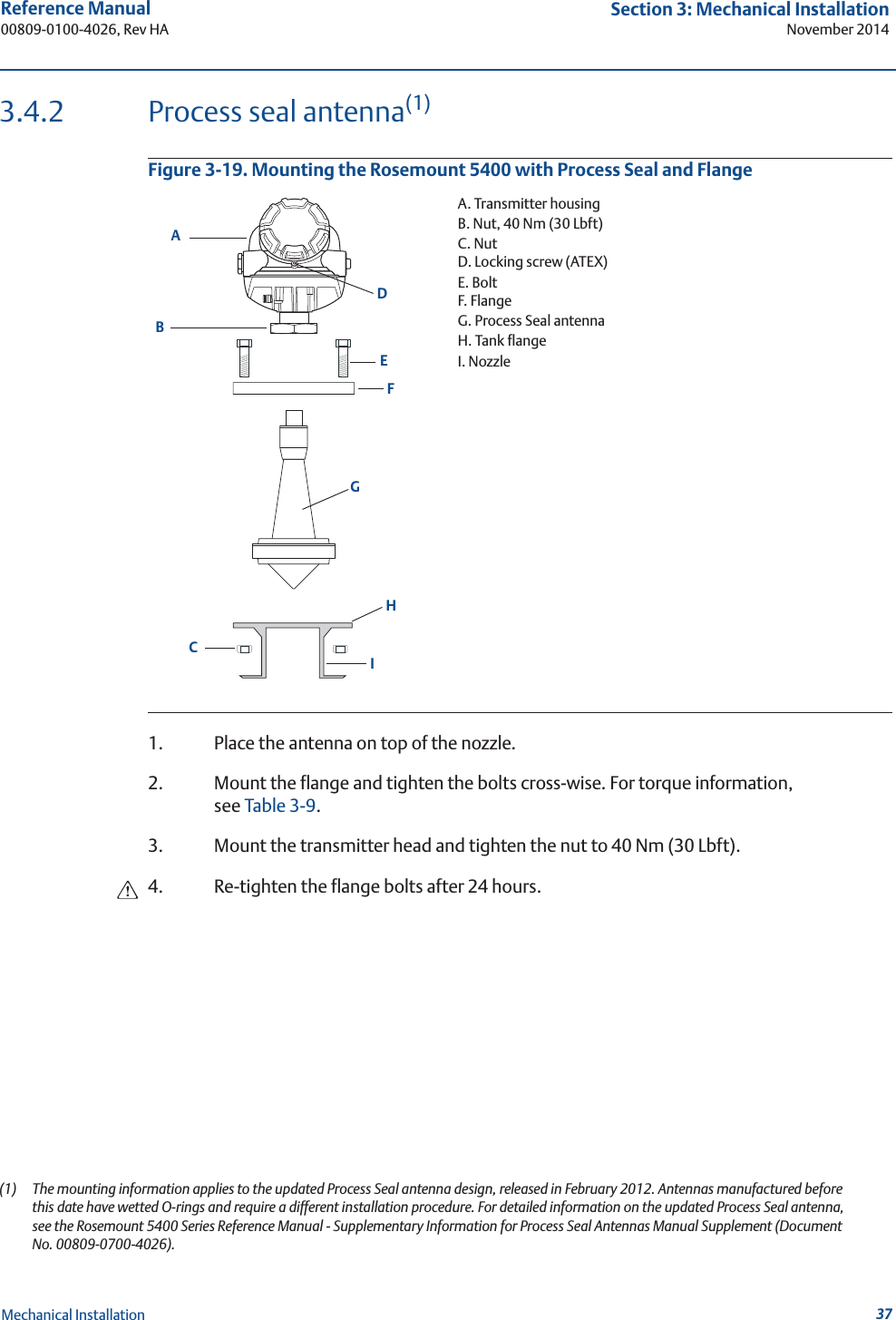
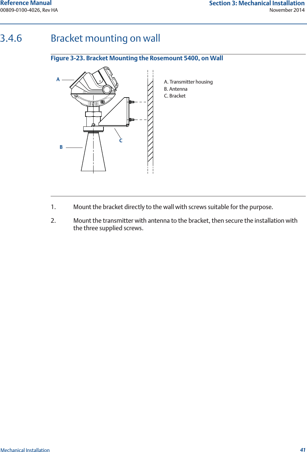
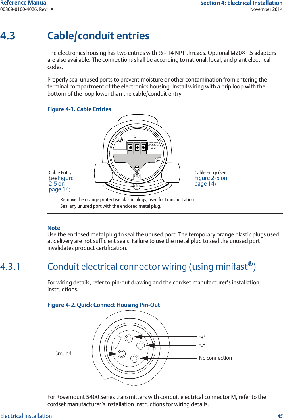
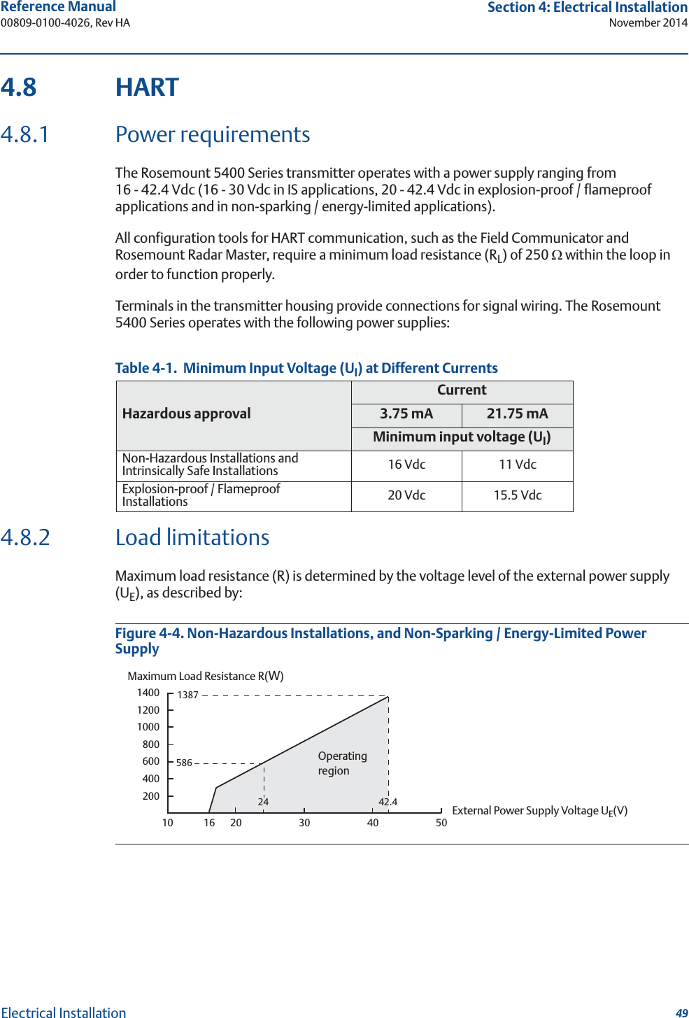
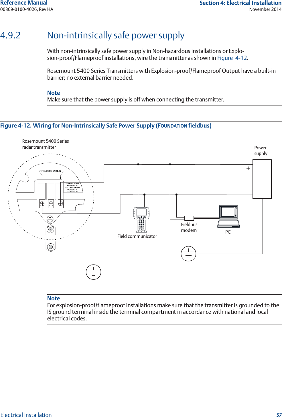
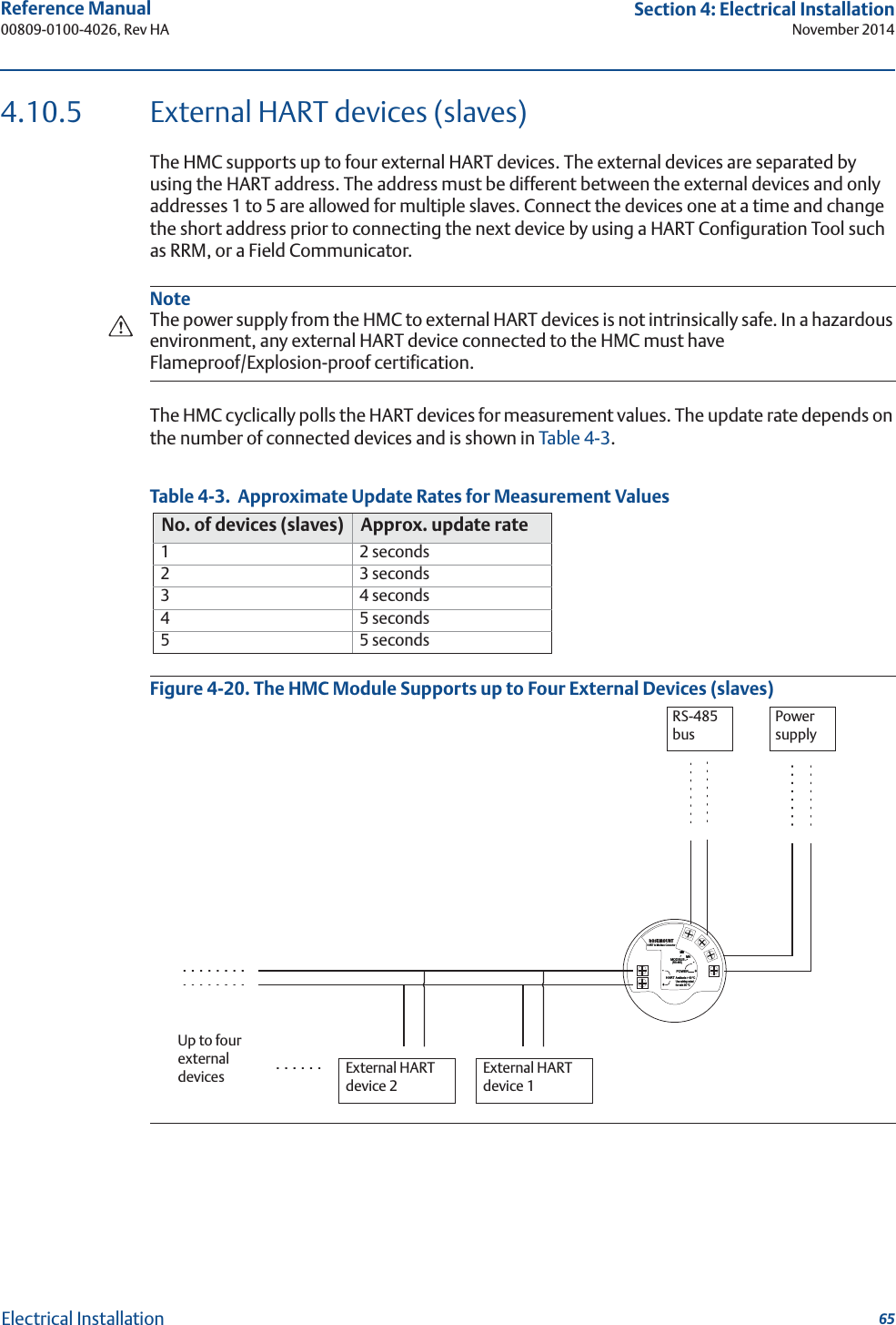
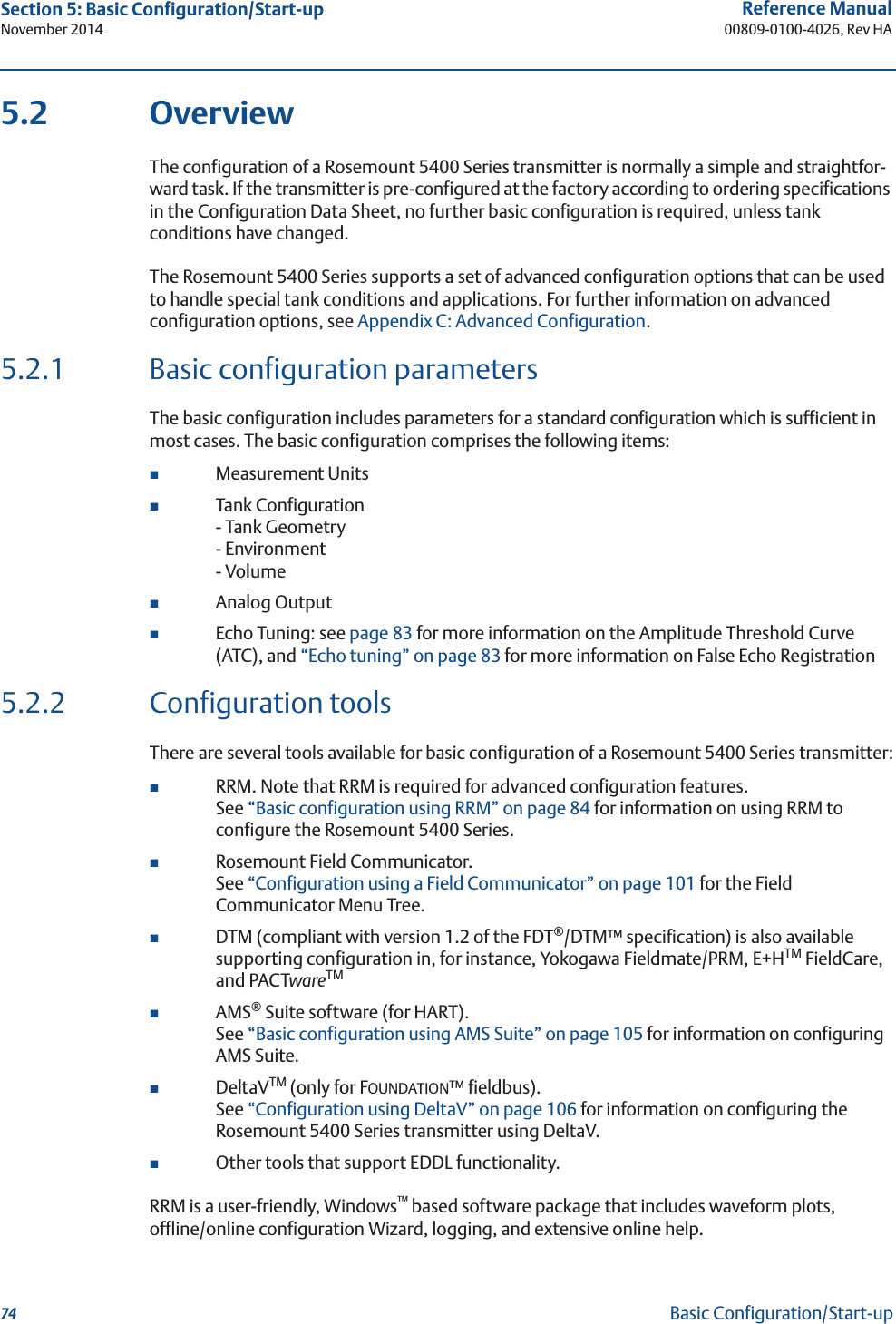
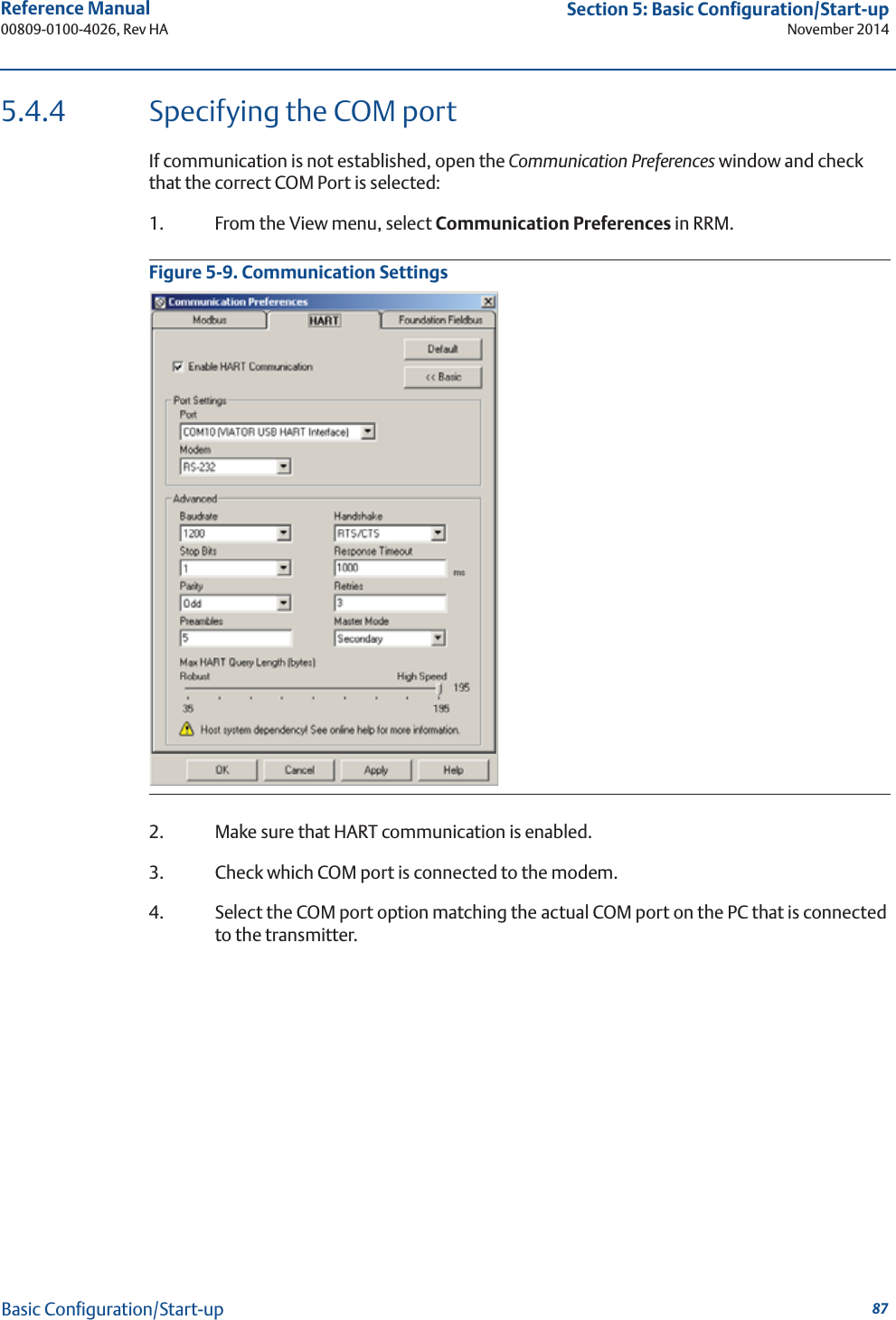
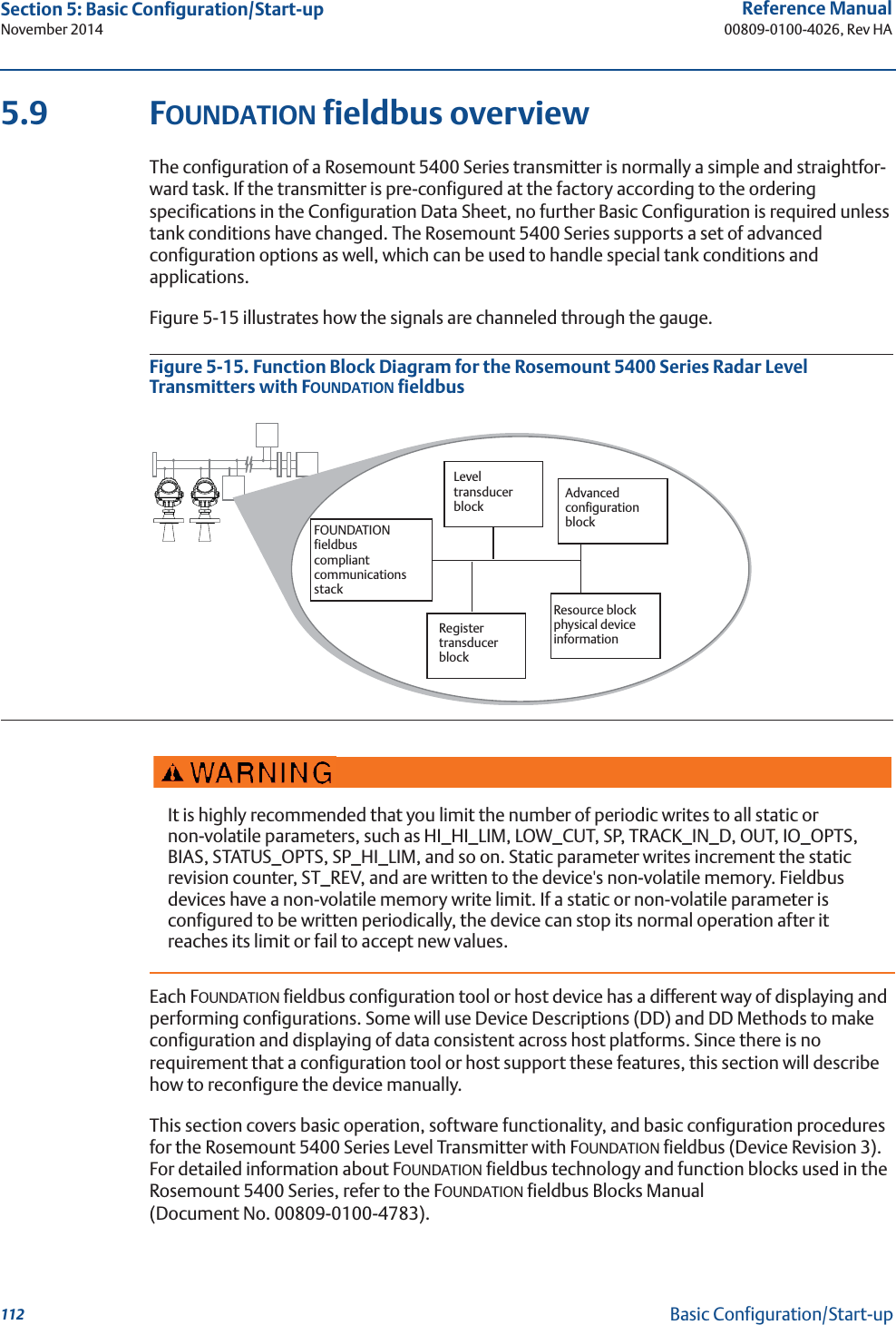
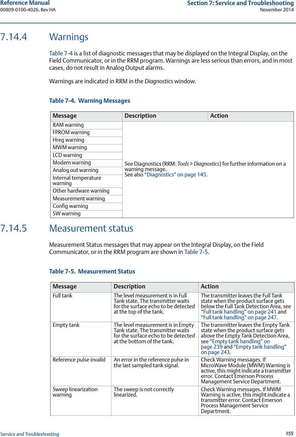
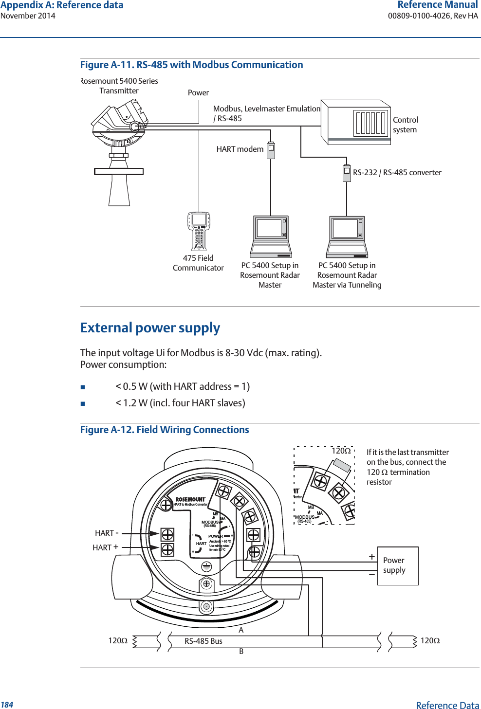
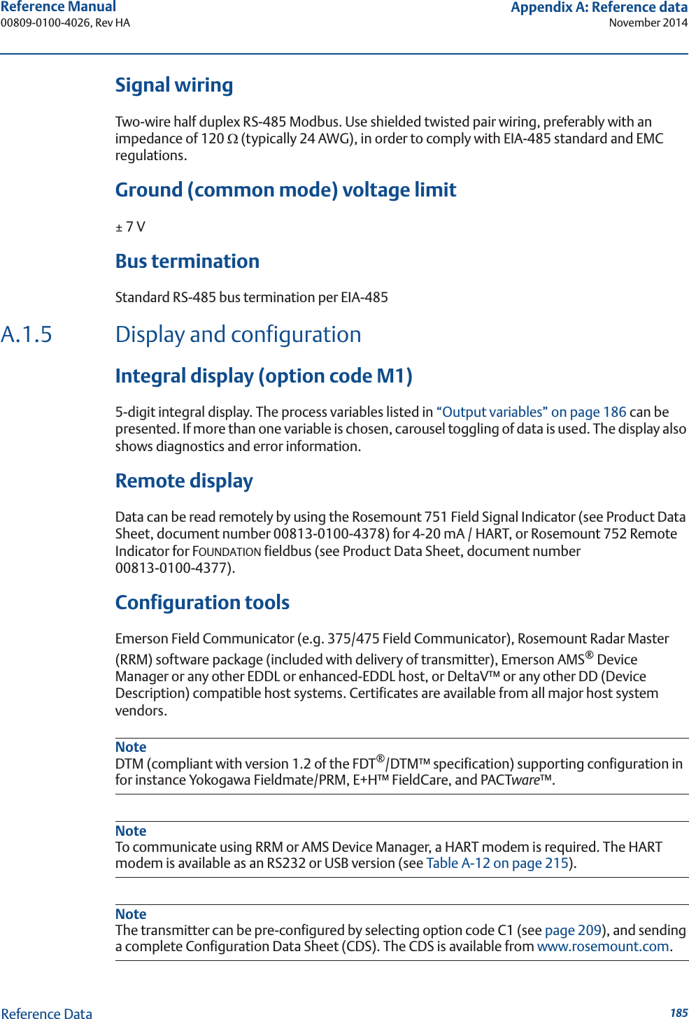
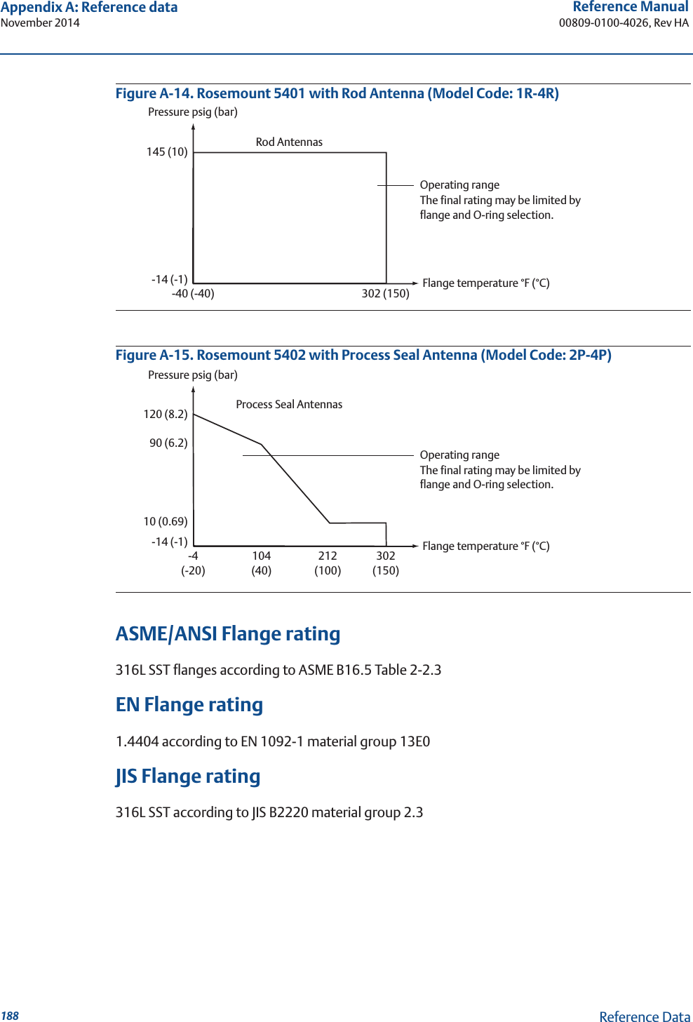
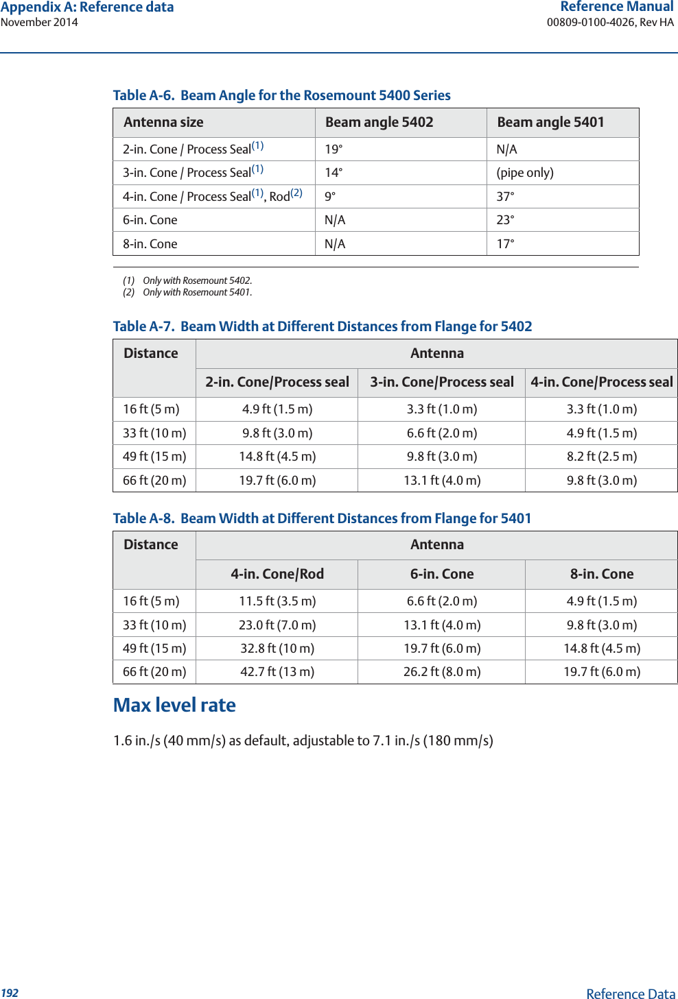
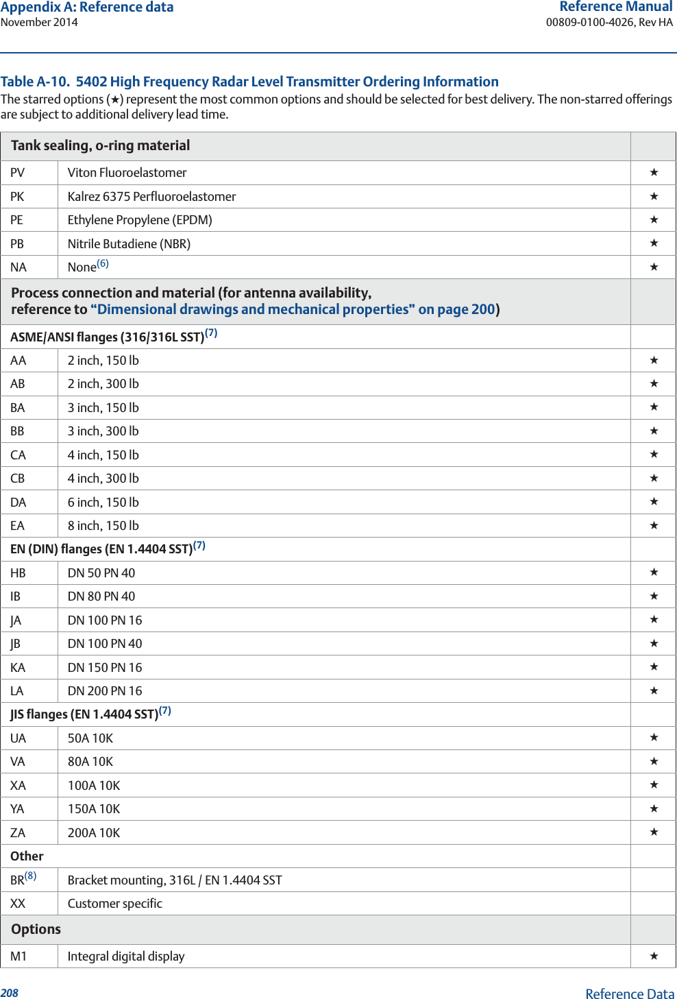
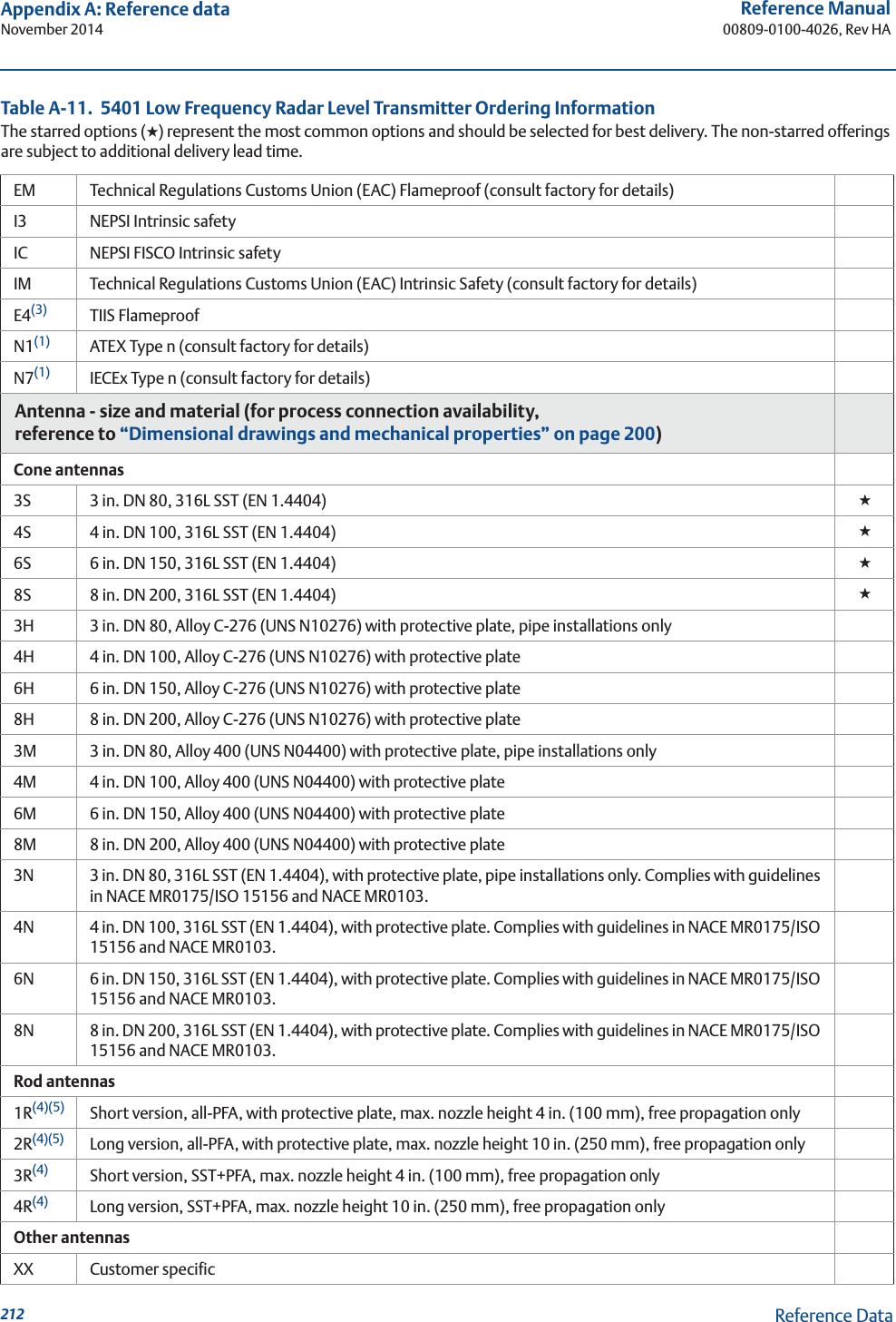
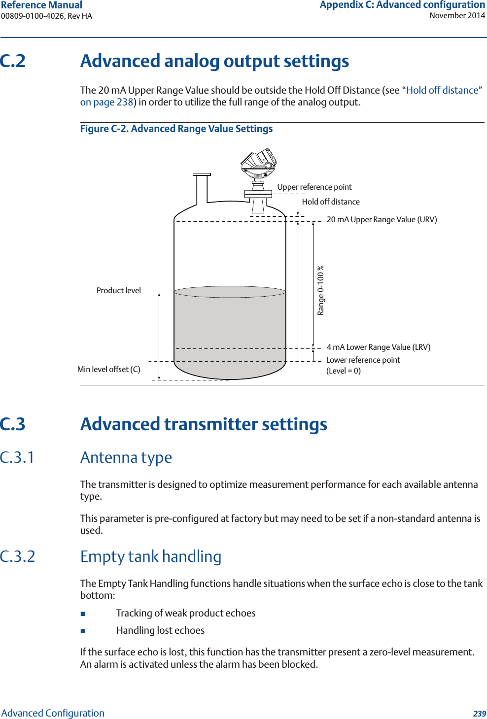
![33Reference Manual 00809-0100-4026, Rev HASection 3: Mechanical InstallationNovember 2014Mechanical Installation3.3.8 BeamwidthThe following recommendations should be considered when mounting the transmitter:The transmitter should be mounted with as few internal structures as possible within the beam angleThe flat tank wall can be located within the antenna beam angle if there is a minimum distance from the transmitter to the tank wall (see Figure 3-15 for preferred installation)Figure 3-16. Beamwidth at Various Distances from the FlangeTable 3-5. Beamwidth for the Rosemount 5402 Model (in ft [m])DistanceAntenna2 in. (DN 50) cone/process seal3 in. (DN 80) cone/process seal4 in. (DN 100) cone/process seal16 ft (5 m) 4.9 (1.5) 3.3 (1.0) 3.3 (1.0)33 ft (10 m) 9.8 (3.0) 6.6 (2.0) 4.9 (1.5)49 ft (15 m) 14.8 (4.5) 9.8 (3.0) 8.2 (2.5)66 ft (20 m) 19.7 (6.0) 13.1 (4.0) 9.8 (3.0)Distance5401(low frequency)5402(high frequency)16 ft (5 m)33 ft (10 m)49 ft (15 m)66 ft (20 m)Beamwidth](https://usermanual.wiki/Rosemount-Tank-Radar/05402/User-Guide-2448693-Page-45.png)
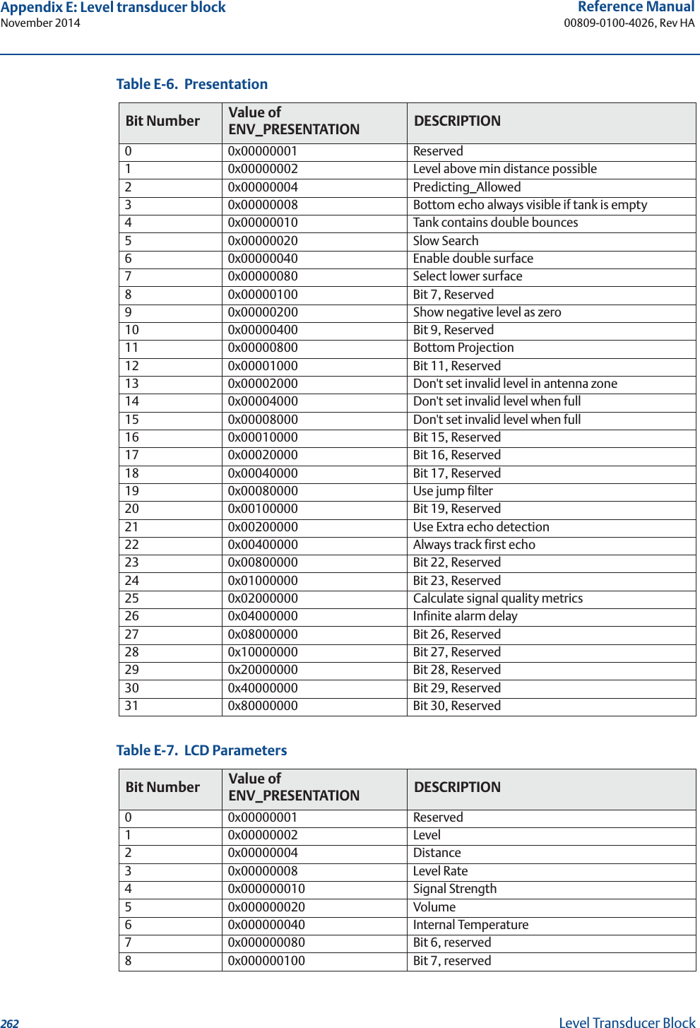
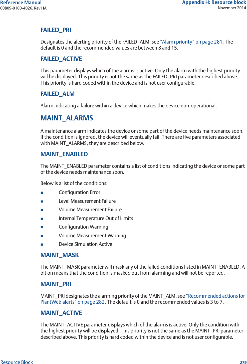
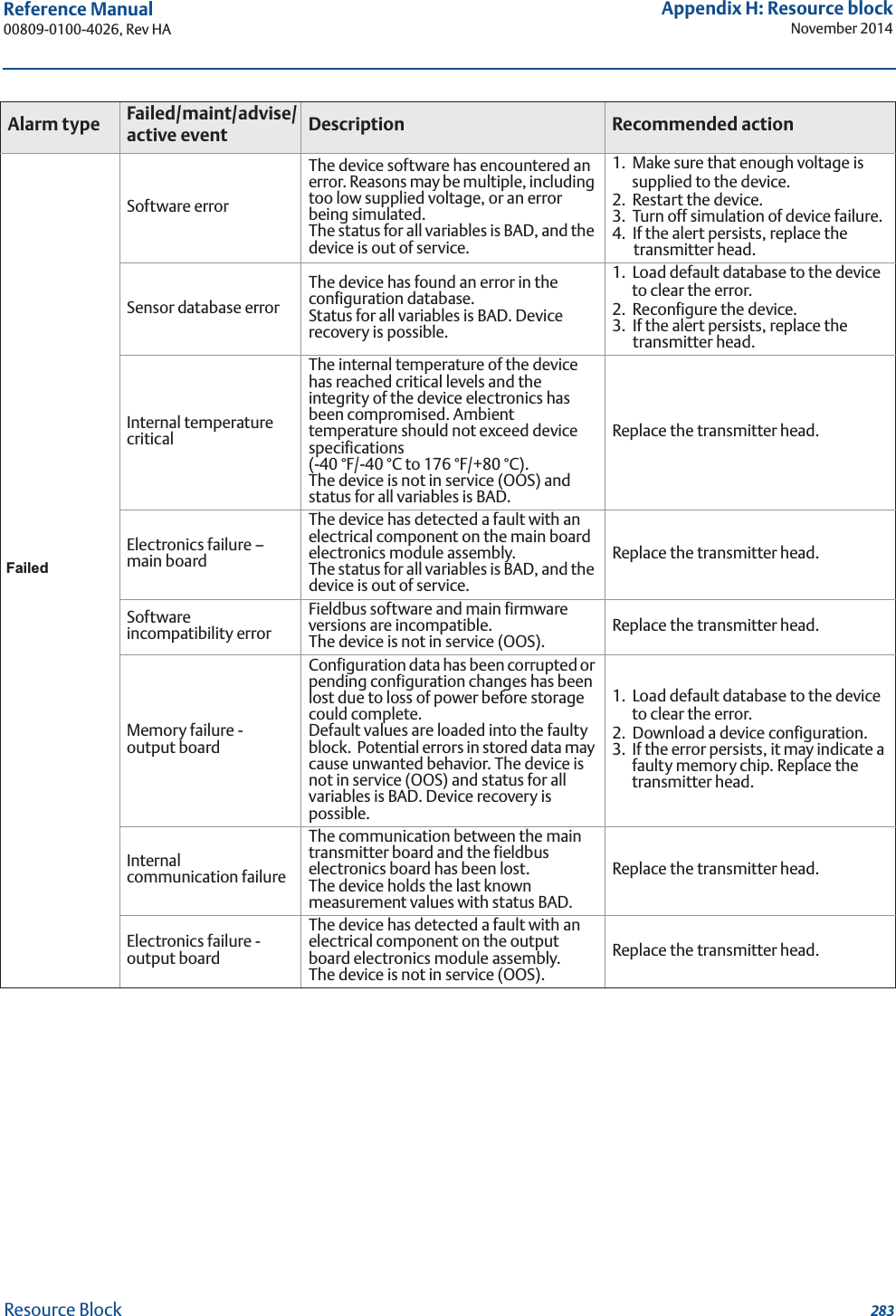
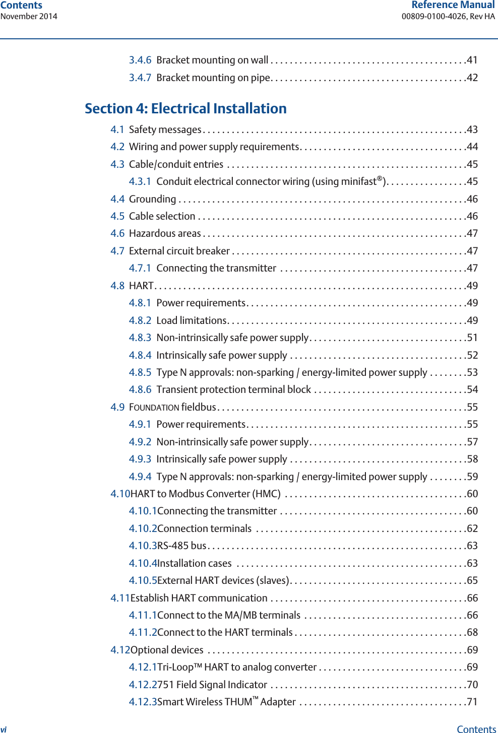
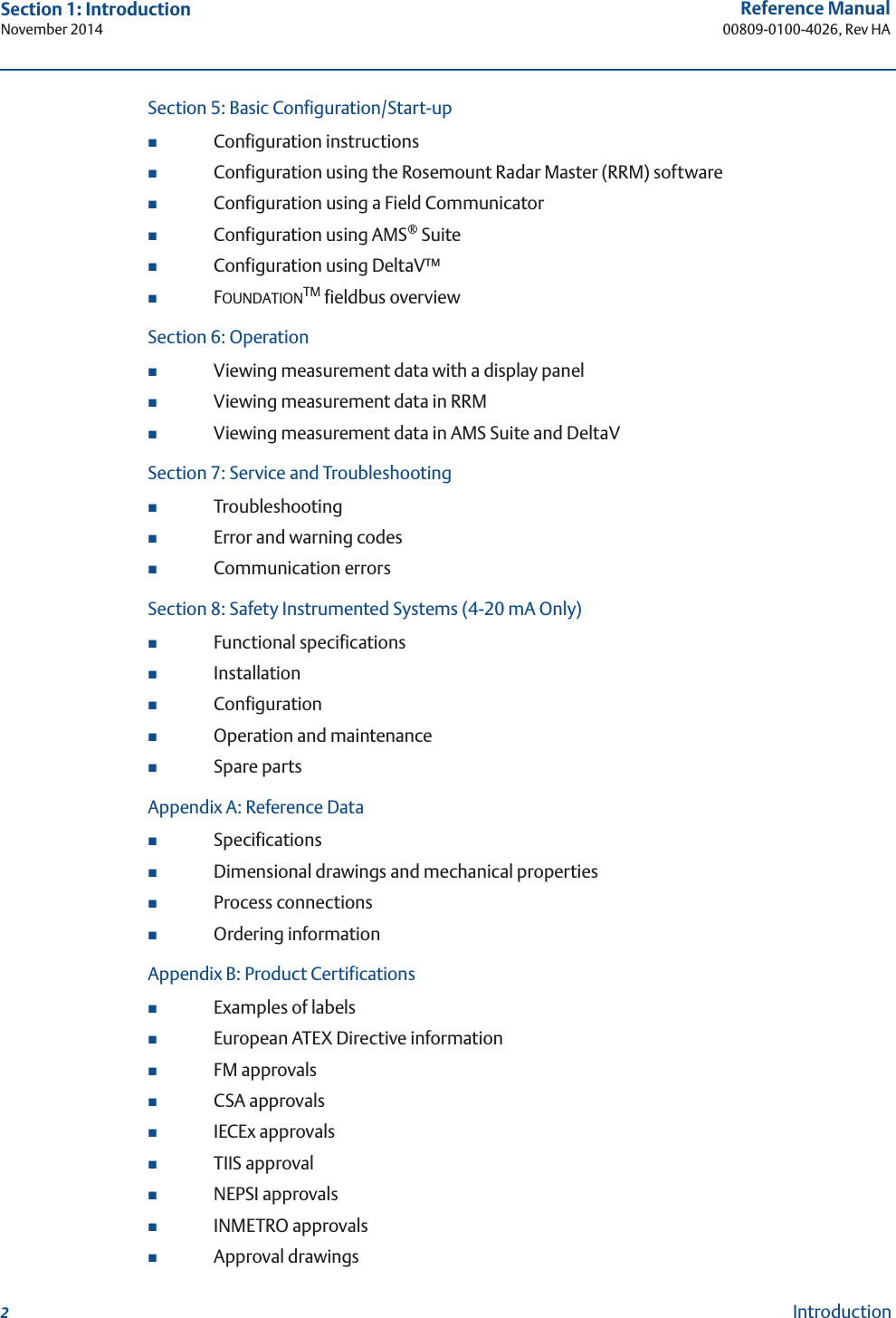
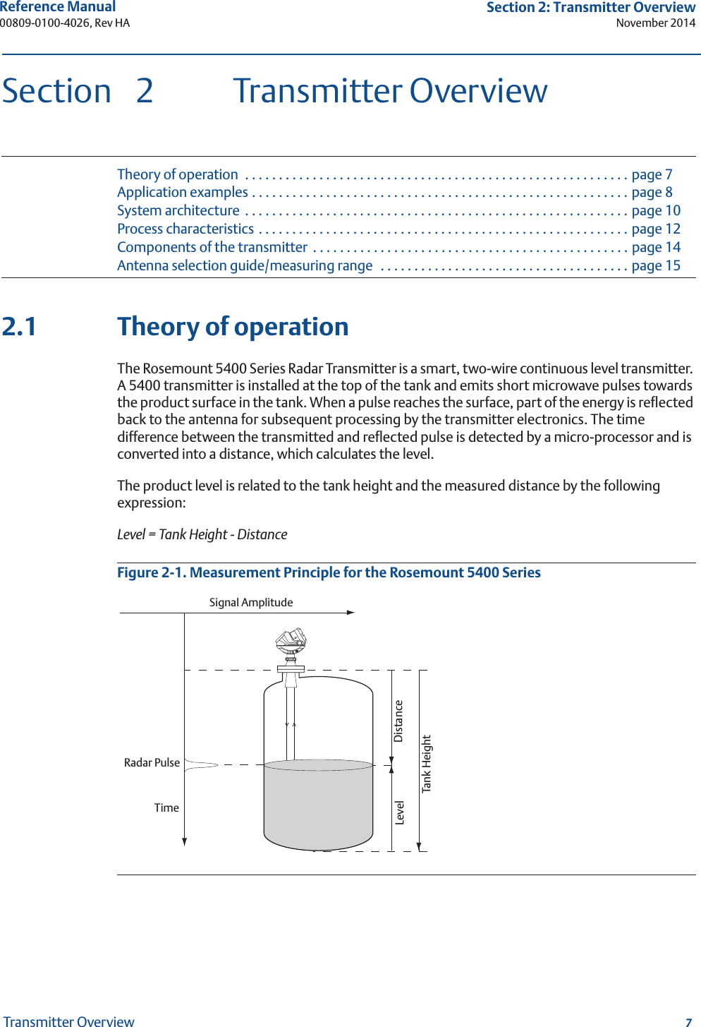
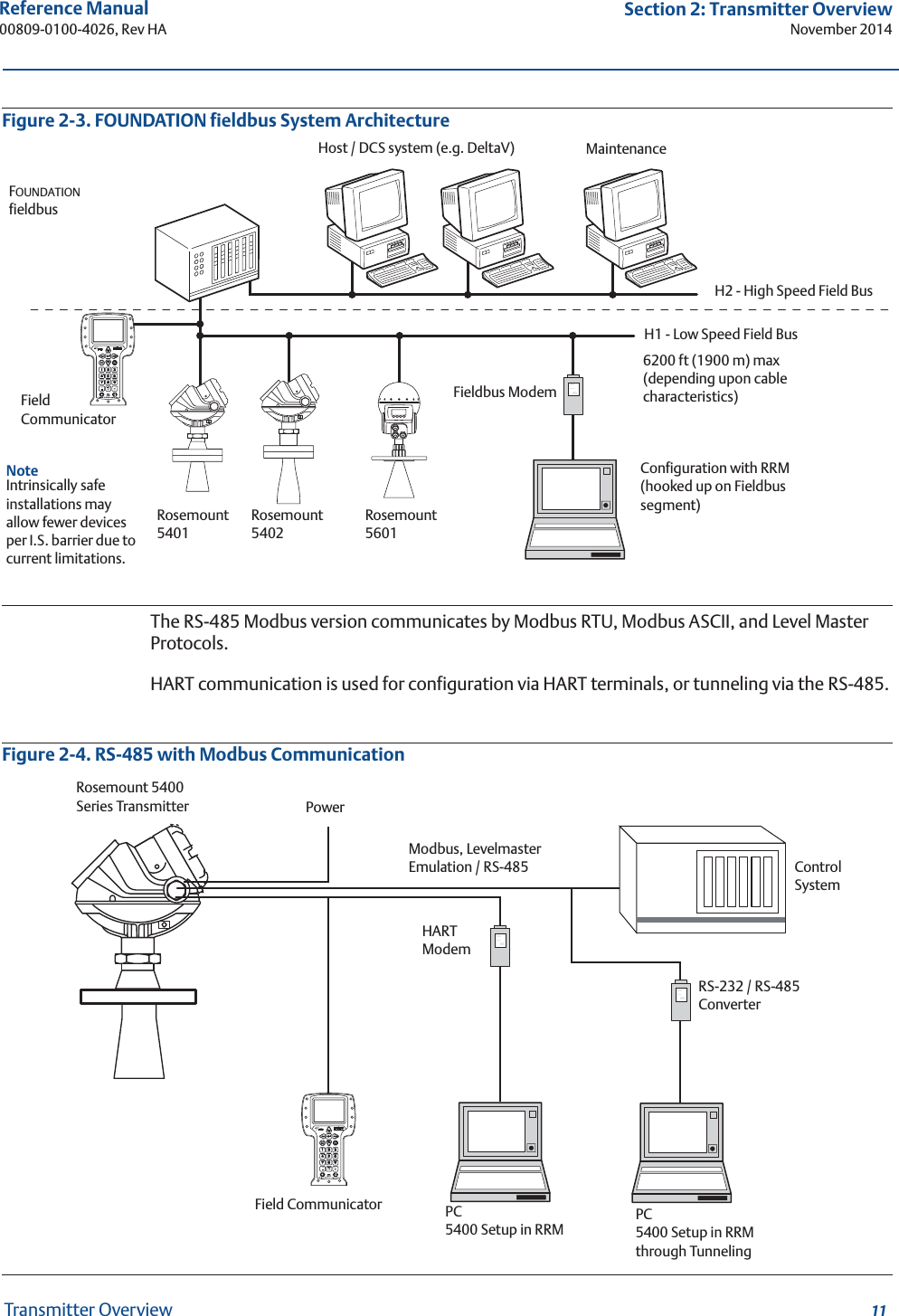
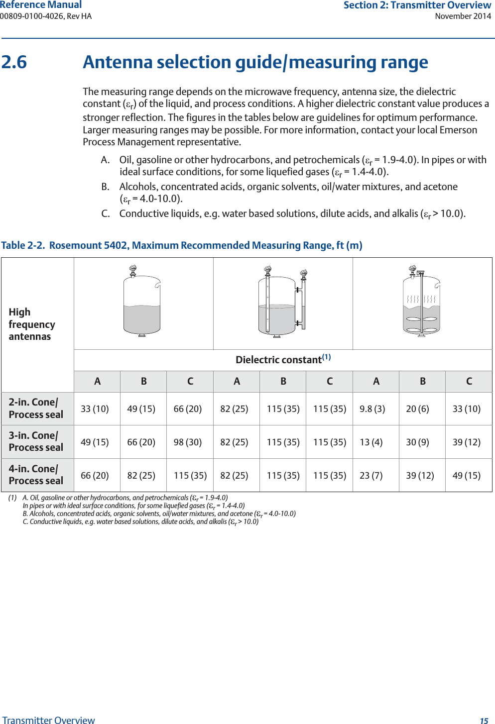
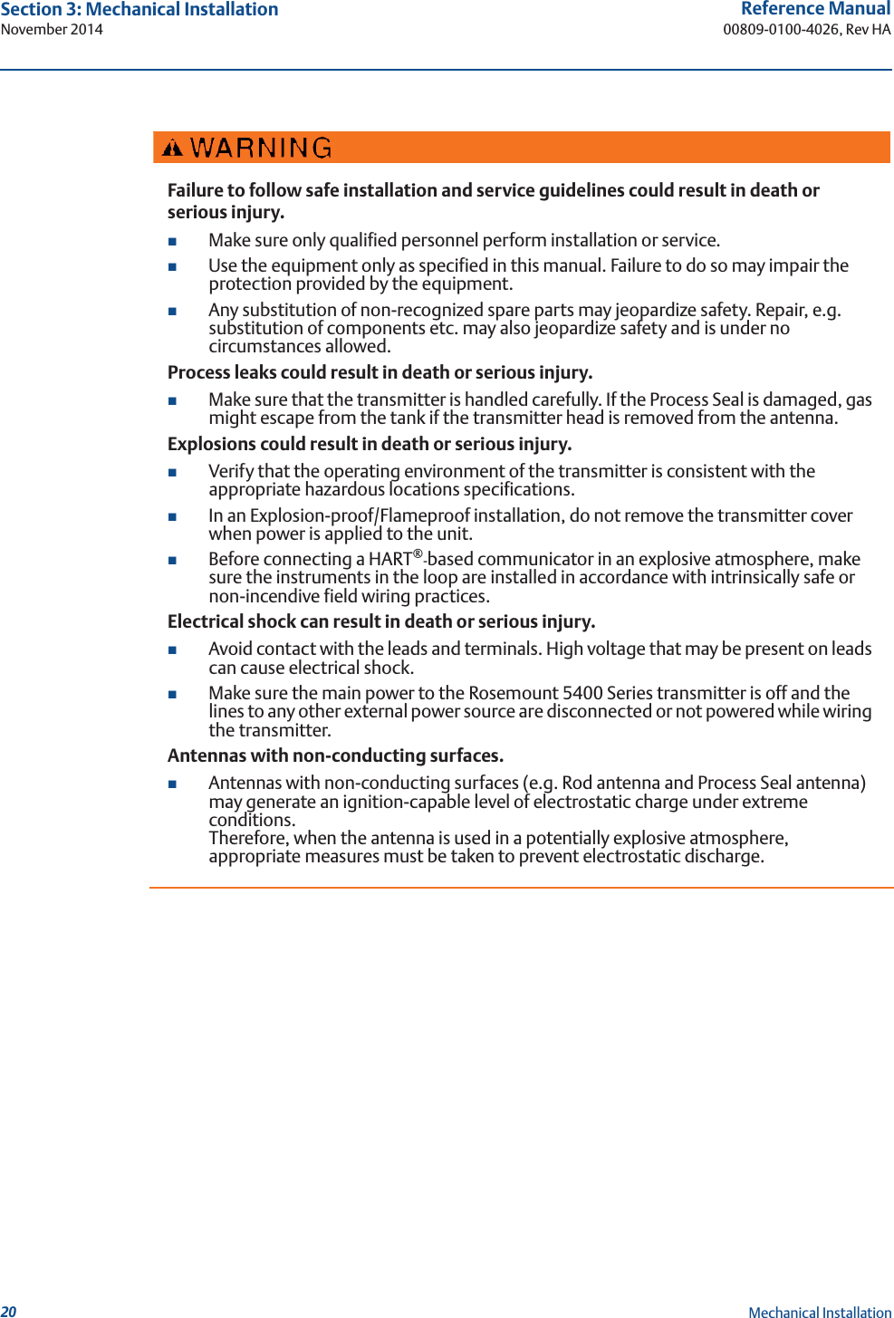
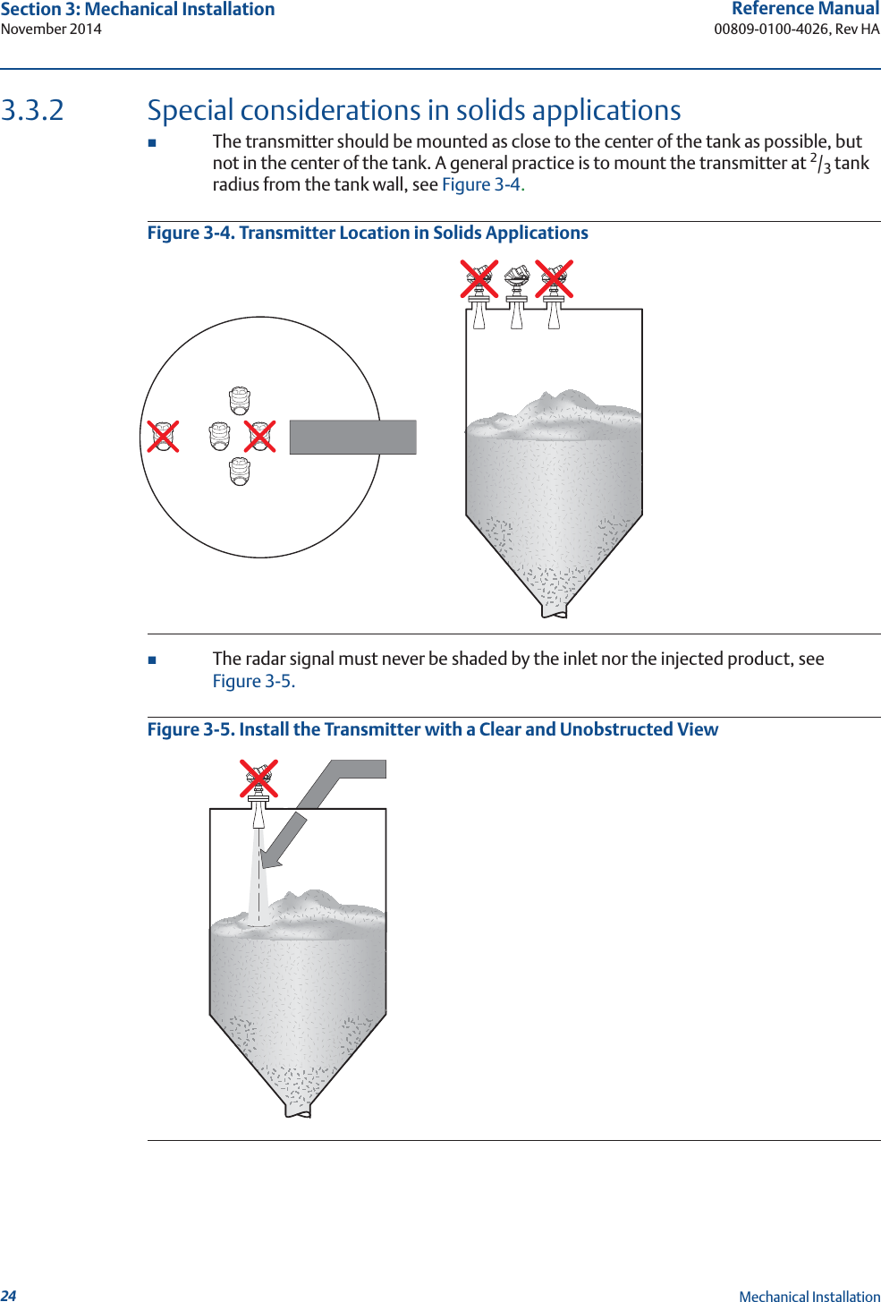
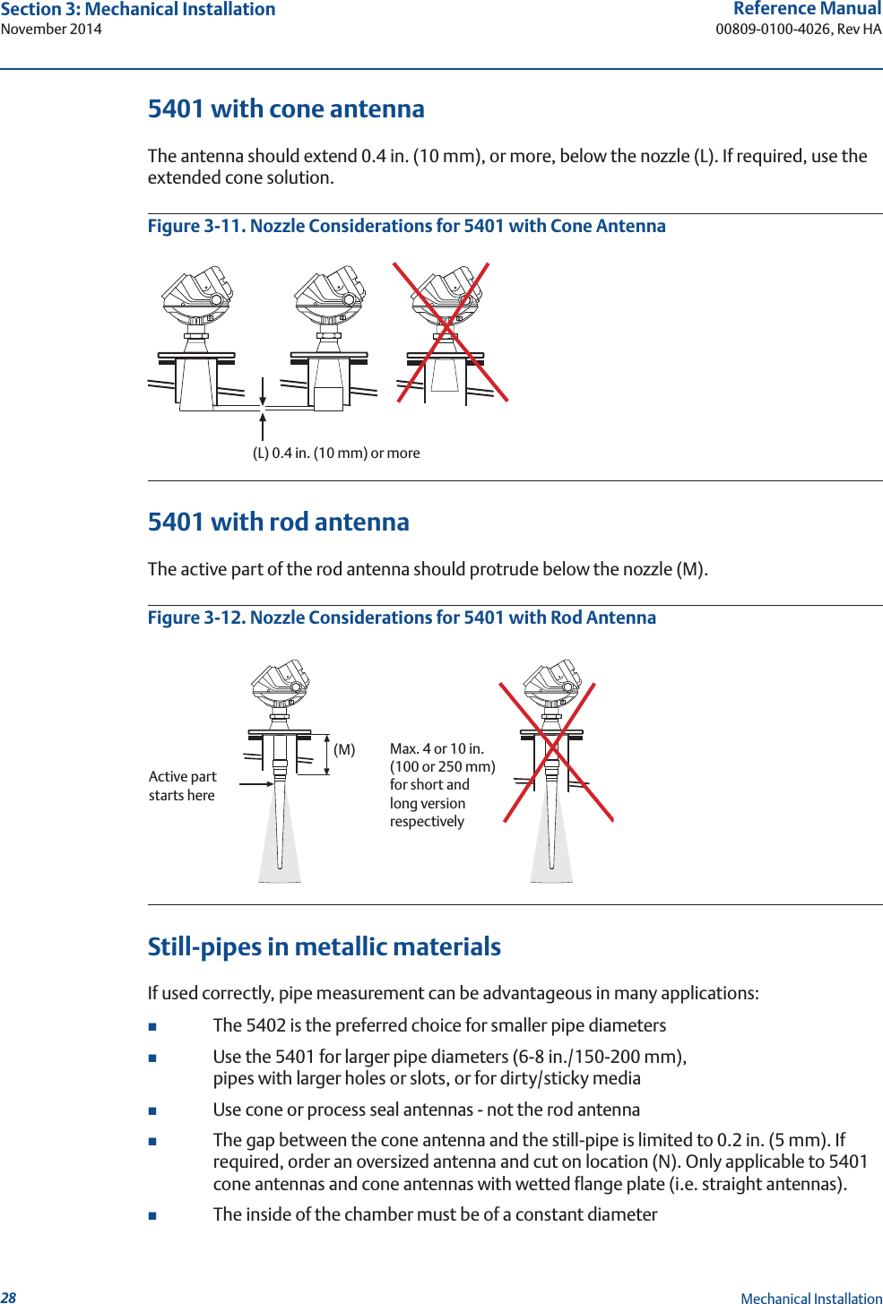
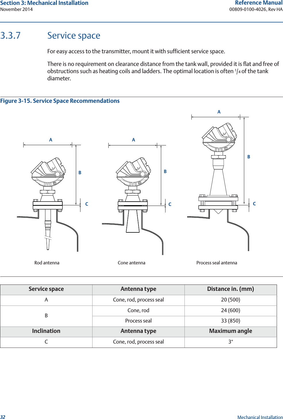
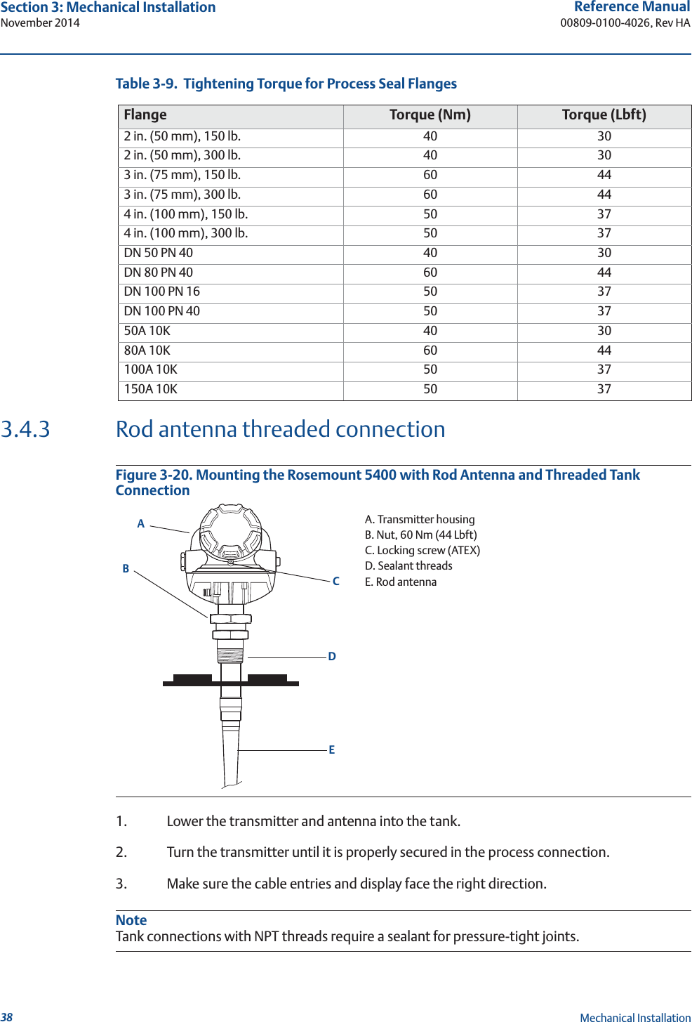
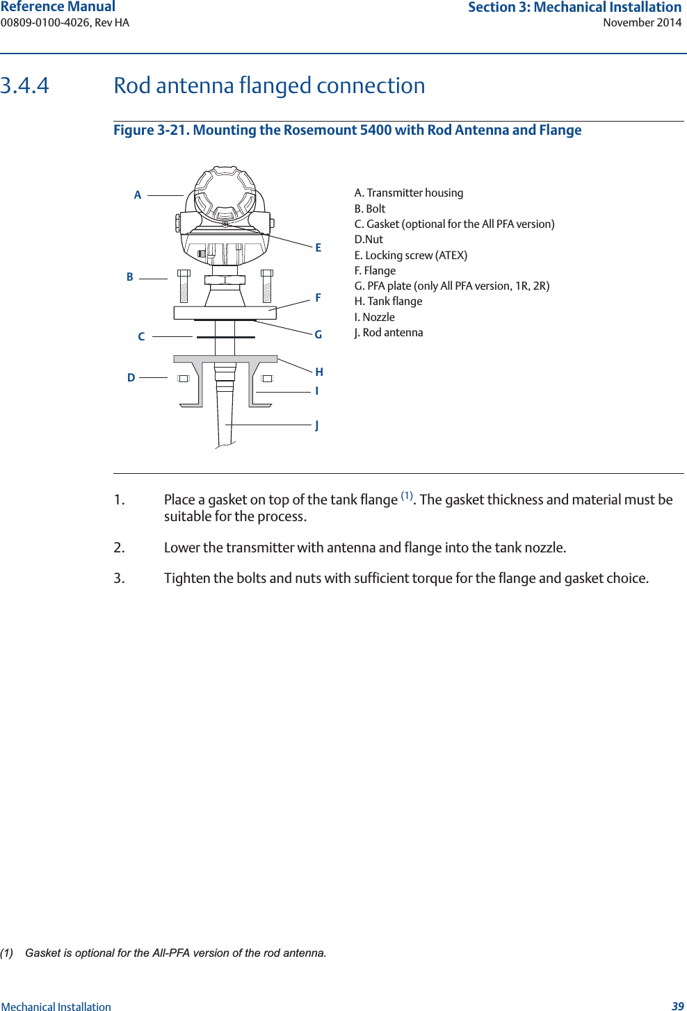
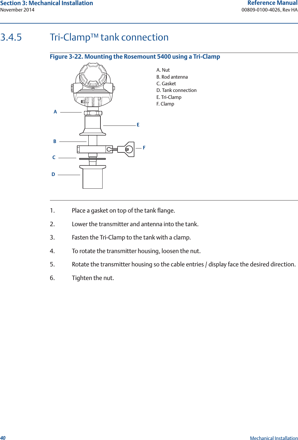
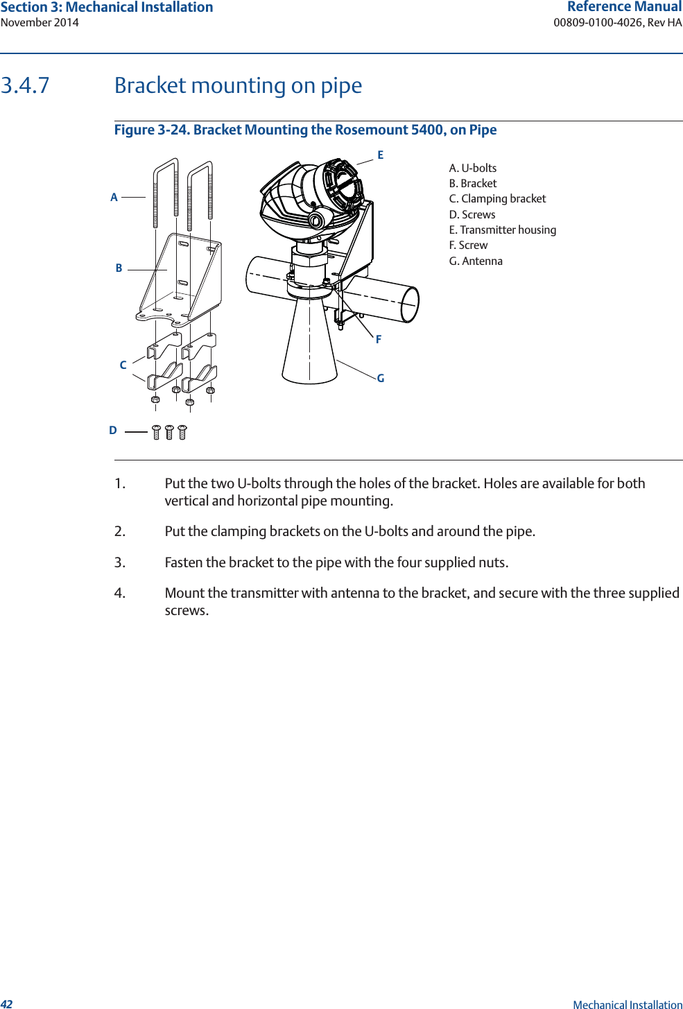
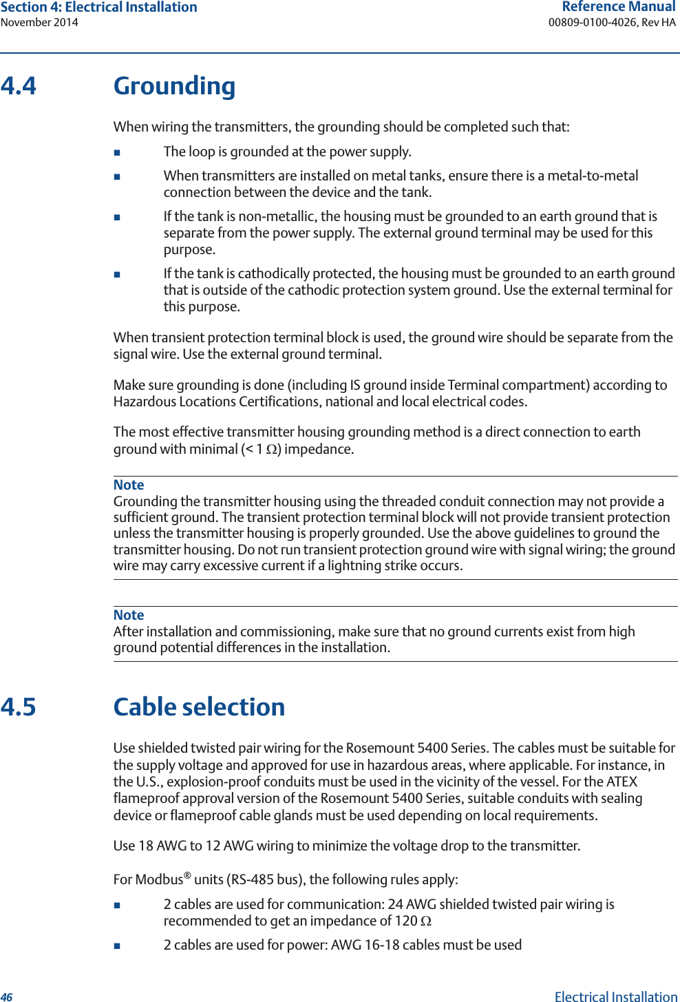
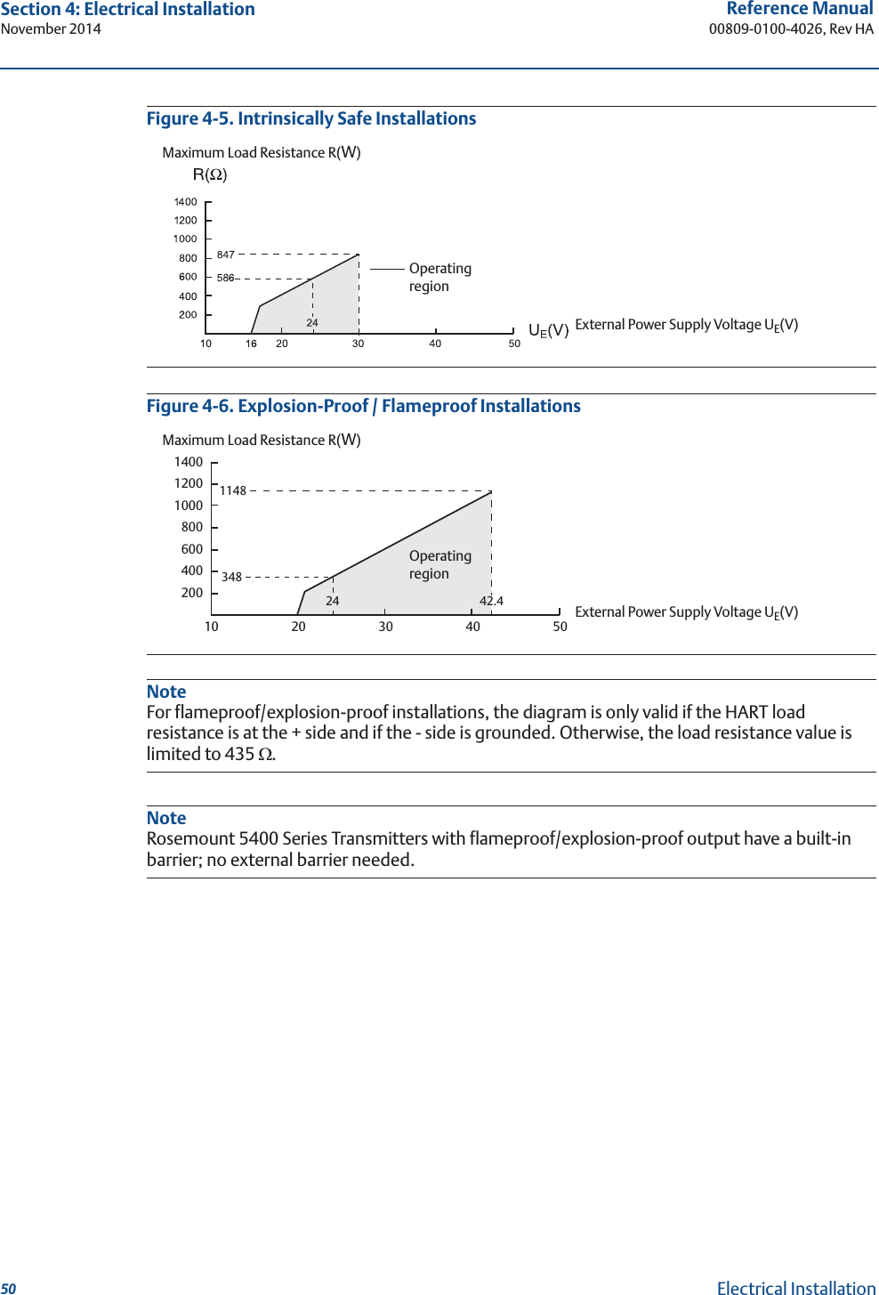
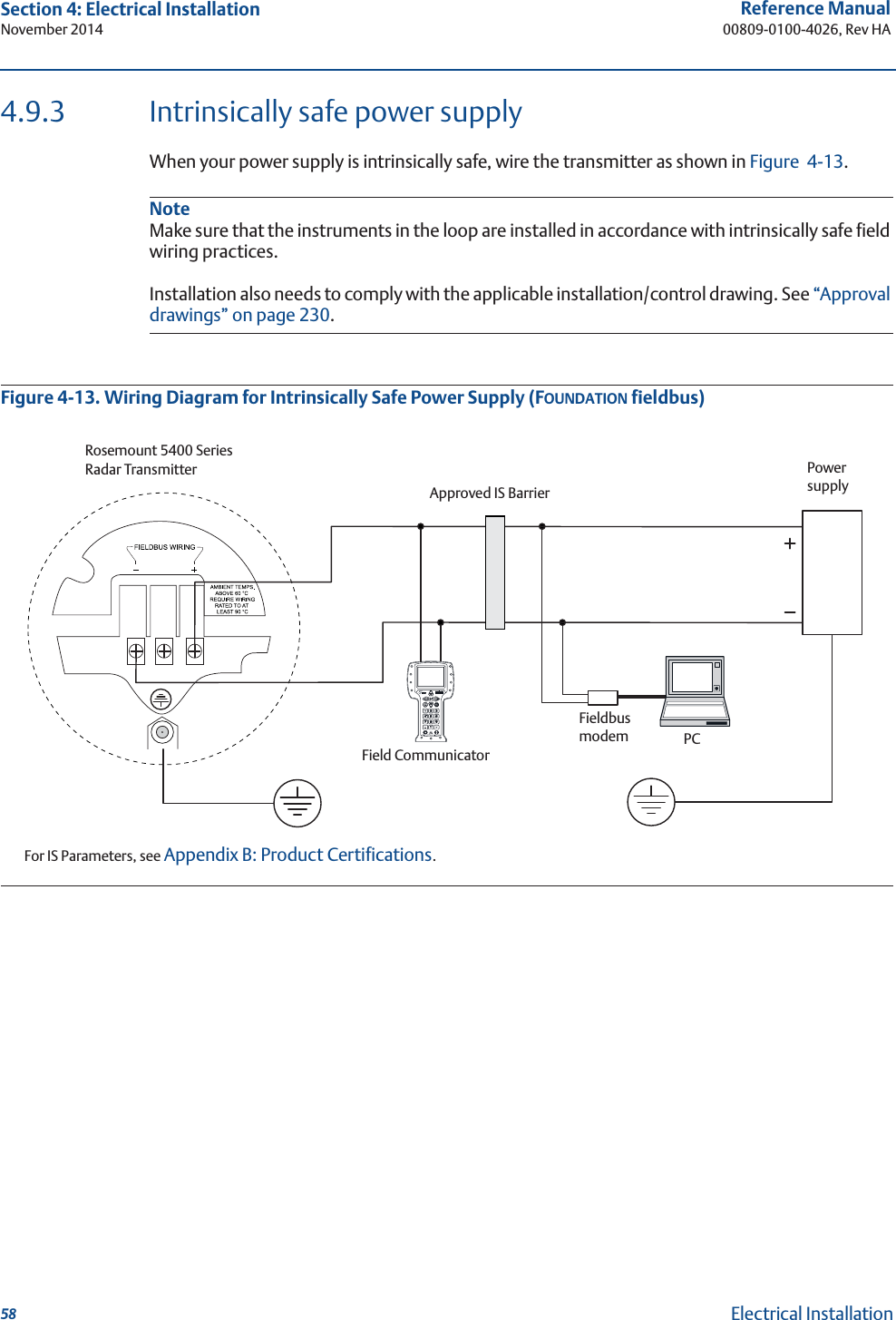
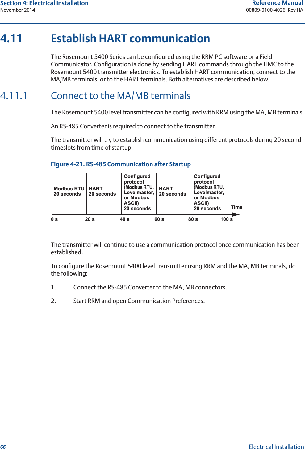
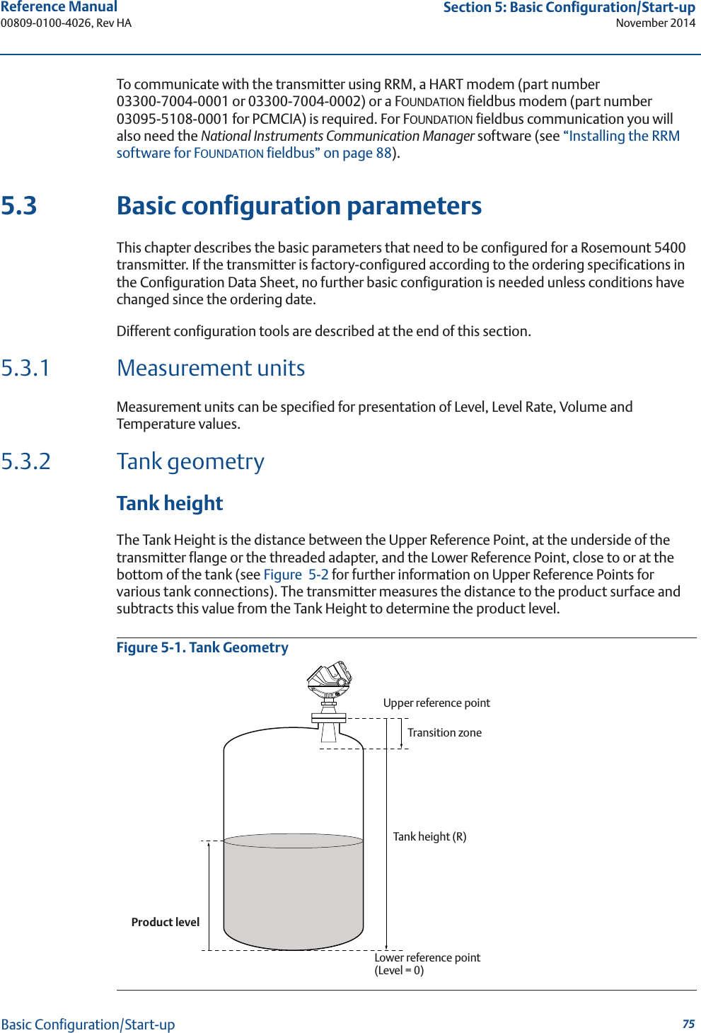
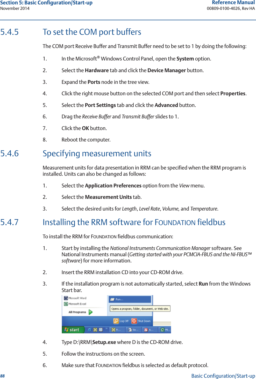
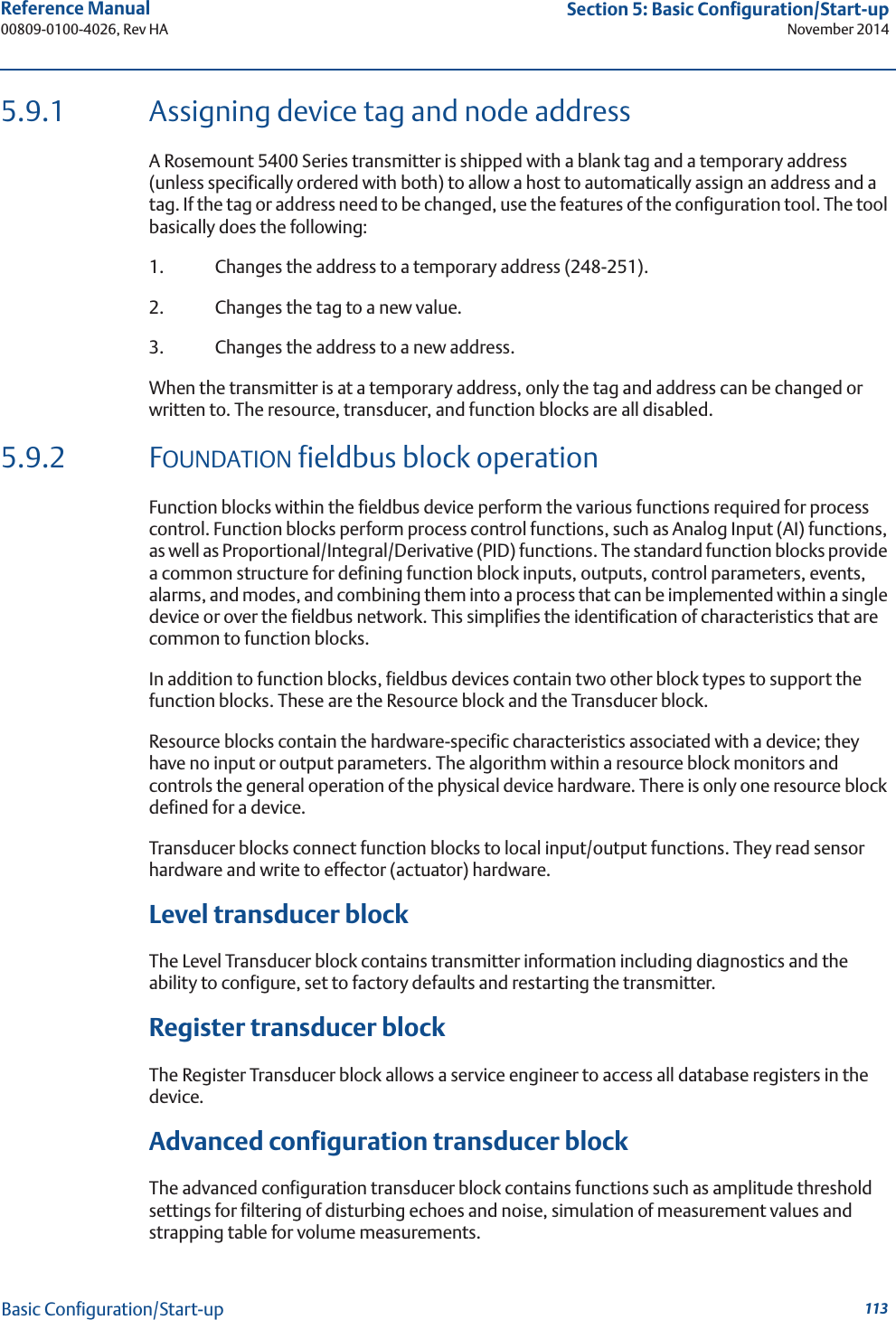
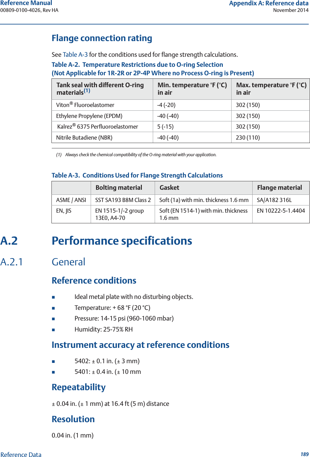
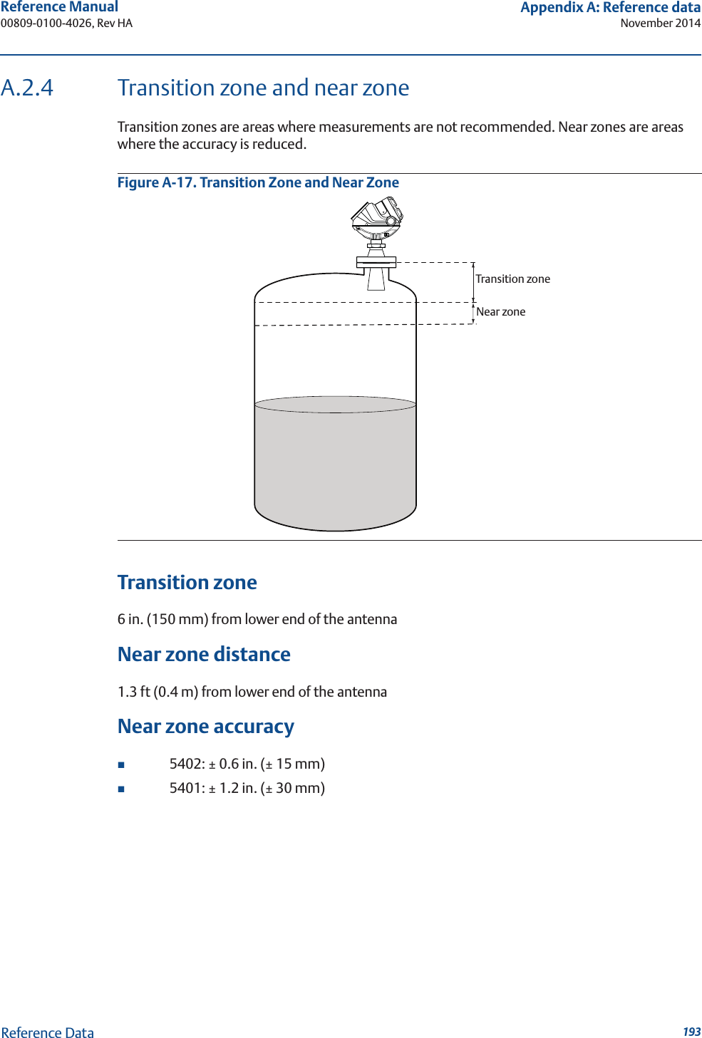
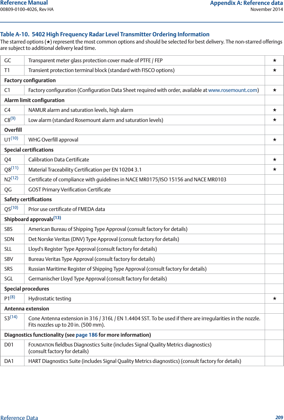
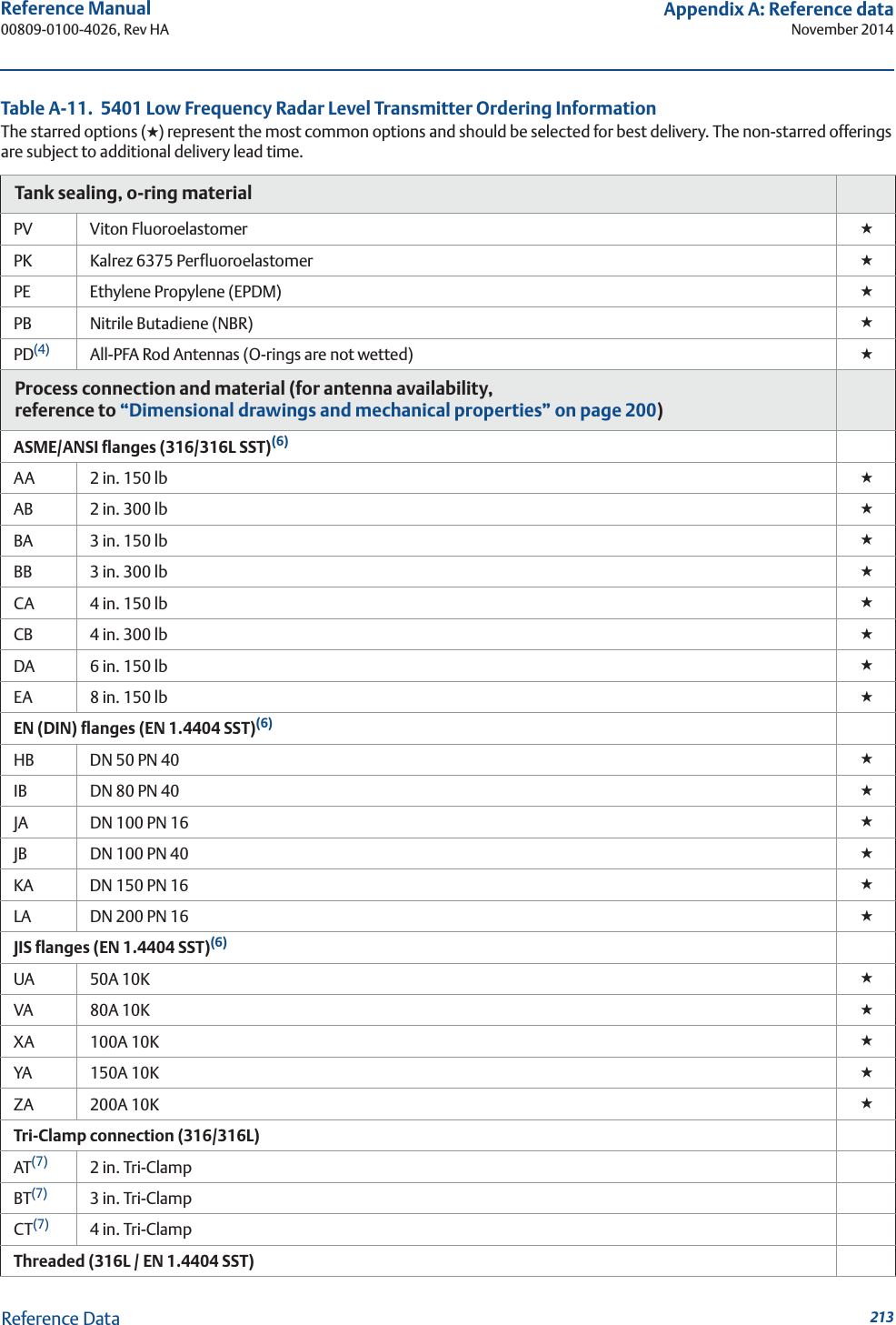
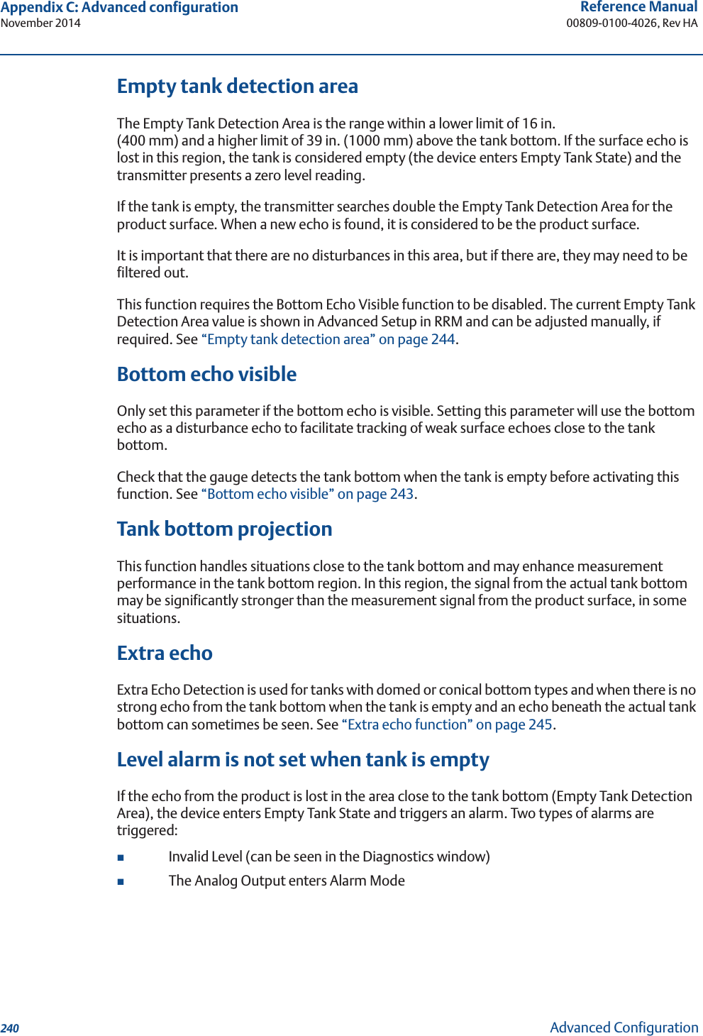
![34Reference Manual00809-0100-4026, Rev HASection 3: Mechanical InstallationNovember 2014Mechanical InstallationTable 3-6. Beamwidth for the Rosemount 5401 Model (in ft [m])Figure 3-17. Beam AngleTable 3-7. Beam Angle for the Rosemount 5402Table 3-8. Beam Angle for the Rosemount 5401DistanceAntenna4 in. (DN 100) cone /rod6 in. (DN 150) cone8 in. (DN 200) cone16 ft (5 m) 9.8 (3..0) 6.6 (2.0) 4.9 (1.5)33 ft (10 m) 21.3 (6.5) 13.1 (4.0) 9.8 (3.0)49 ft (15 m) 32.8 (10) 19.7 (6.0) 14.8 (4.5)66 ft (20 m) 41 (12.5) 26.2 (8.0) 19.7 (6.0)Antenna Beam angle2 in. (50 mm) cone / process seal 19°3 in. (75 mm) cone / process seal 14°4 in. (100 mm) cone / process seal, rod 9°Antenna Beam angle3 in. (75 mm) cone Pipe installations only4 in. (100 mm) cone / rod 37°6 in. (150 mm) cone 23°8 in. (200 mm) cone 17°Beam angle](https://usermanual.wiki/Rosemount-Tank-Radar/05402/User-Guide-2448693-Page-46.png)
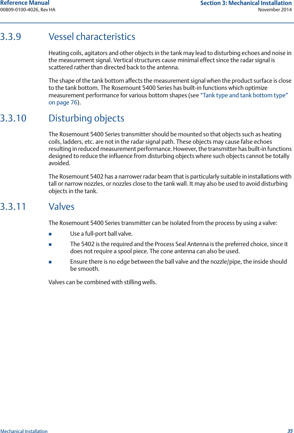
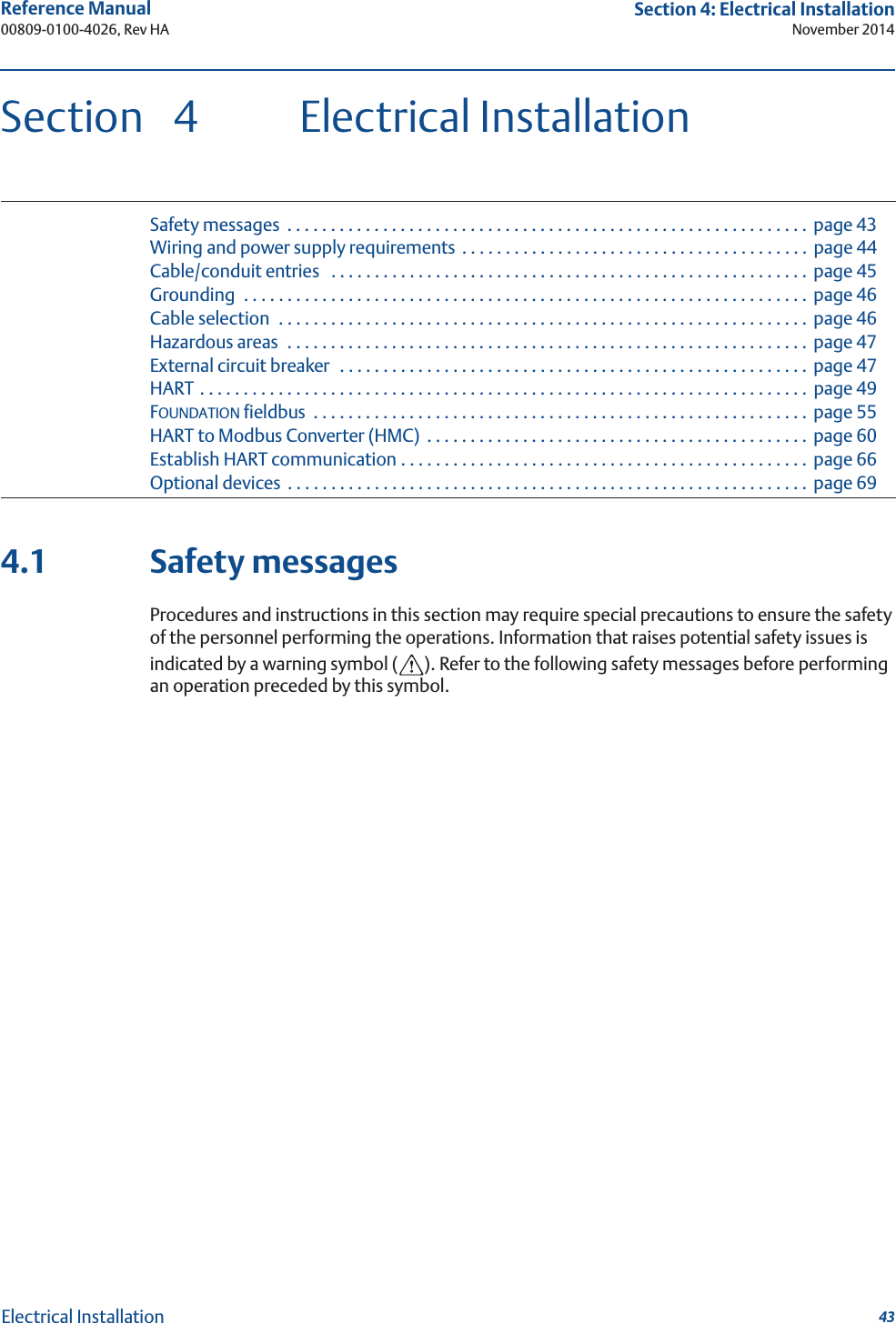
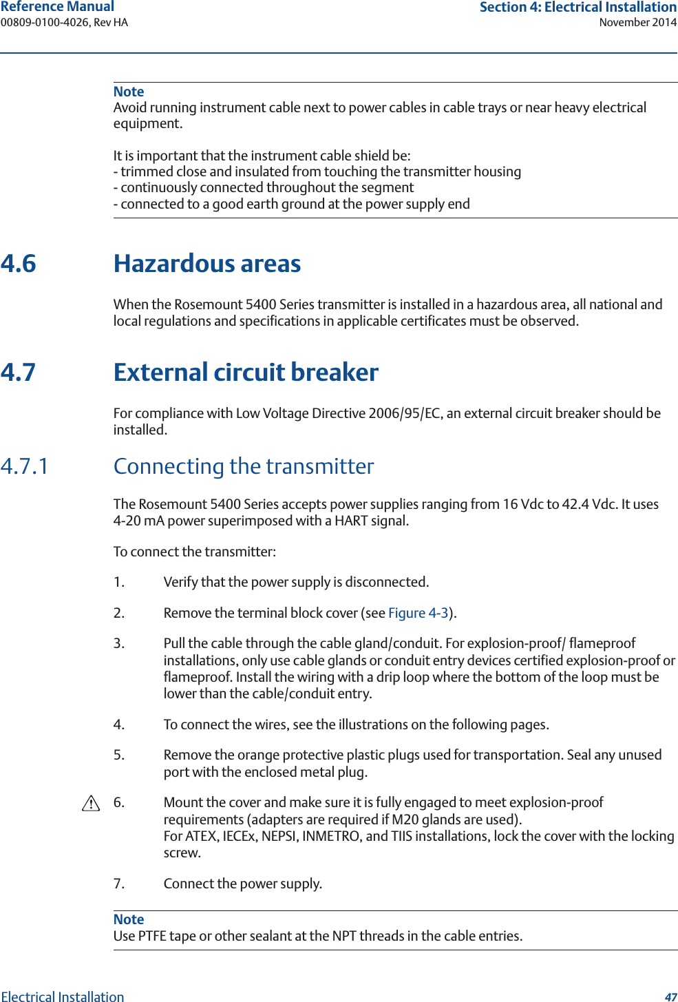
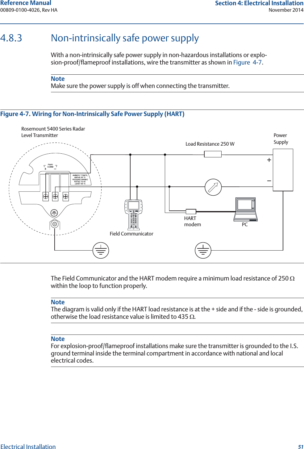
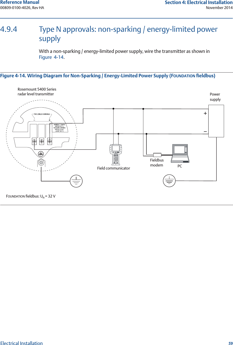
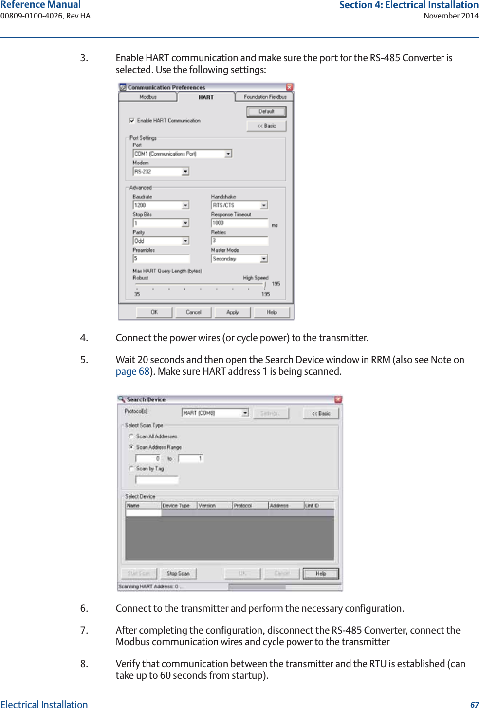

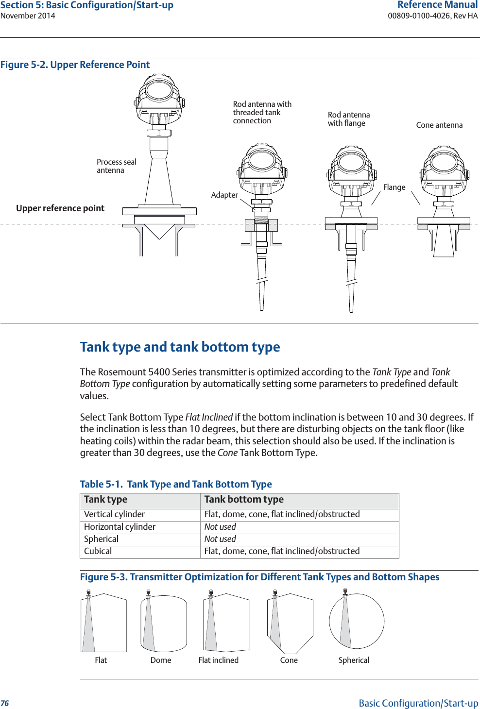
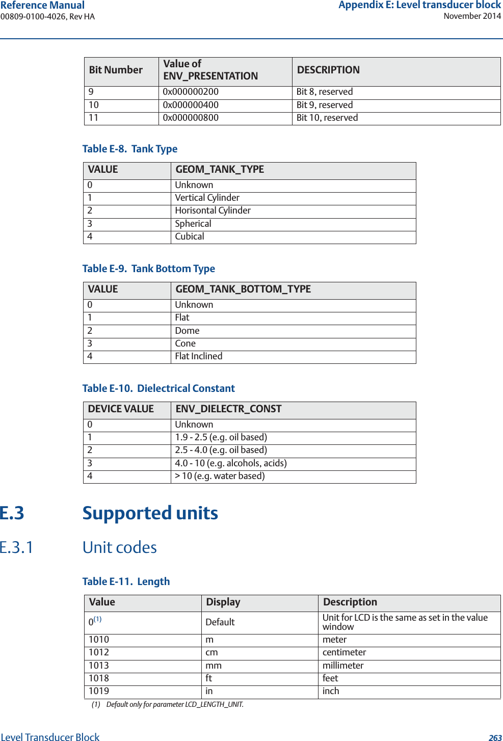
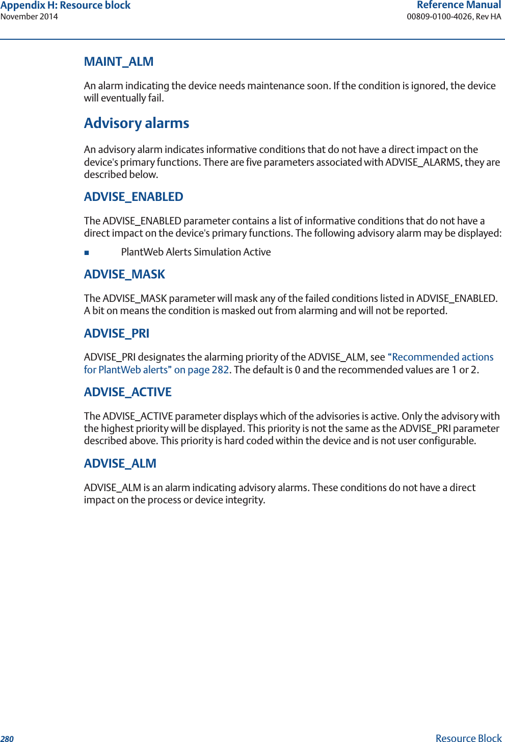
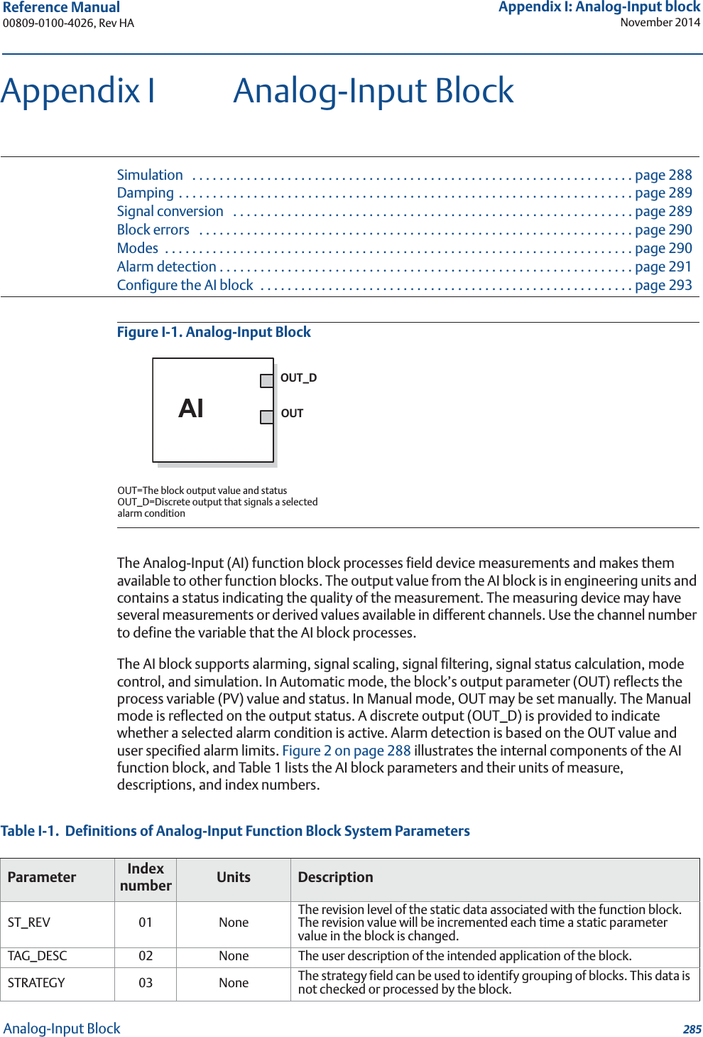
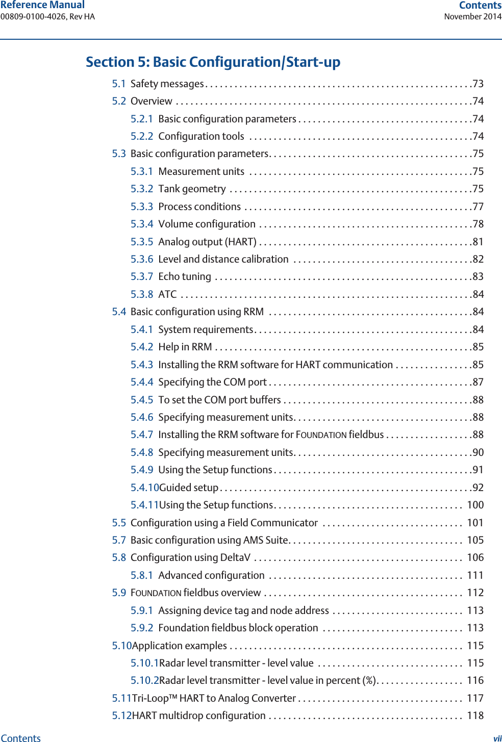
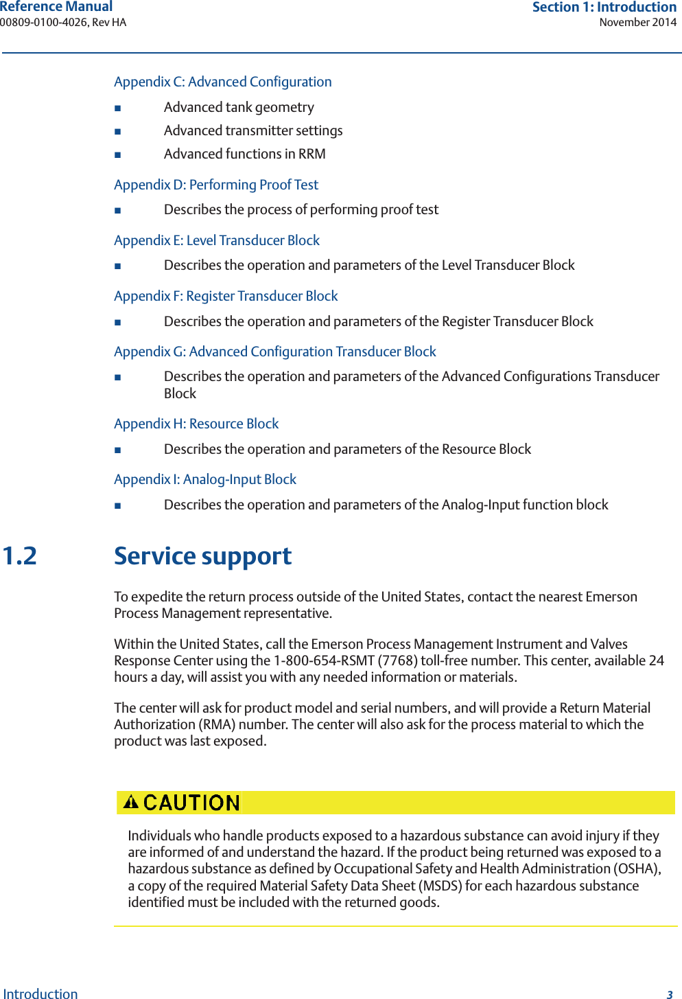
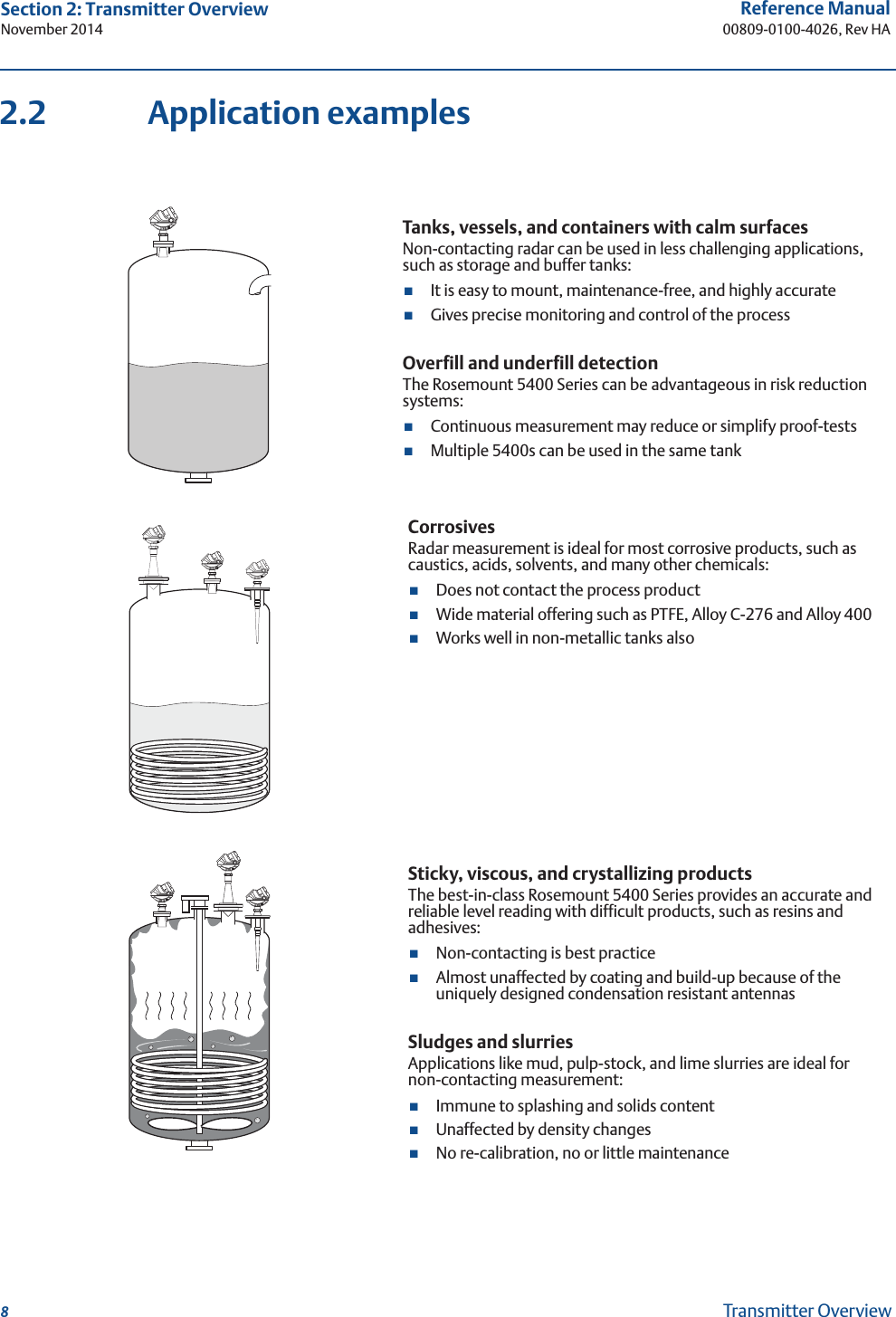
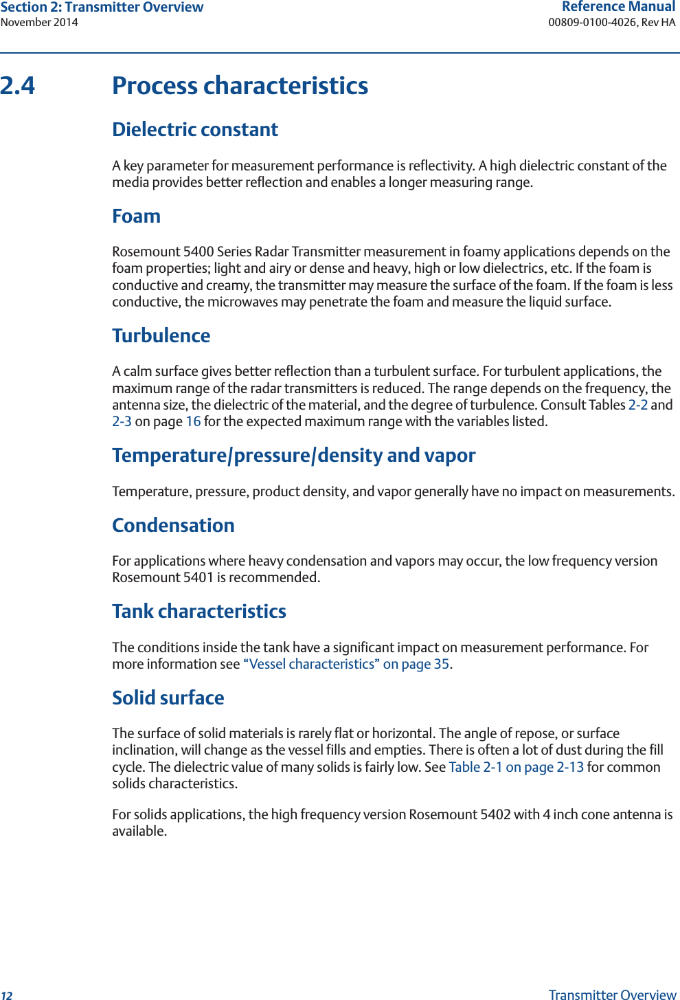
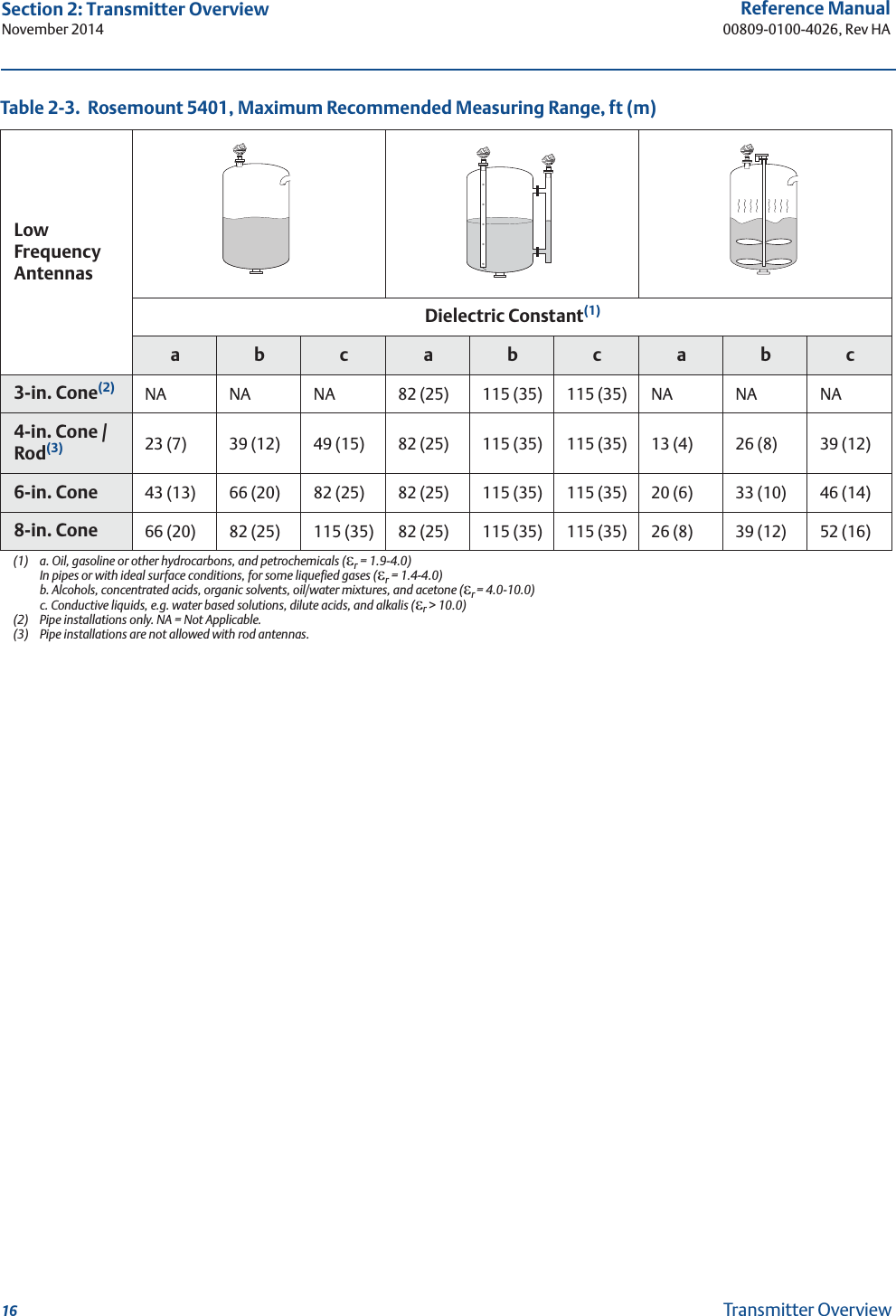
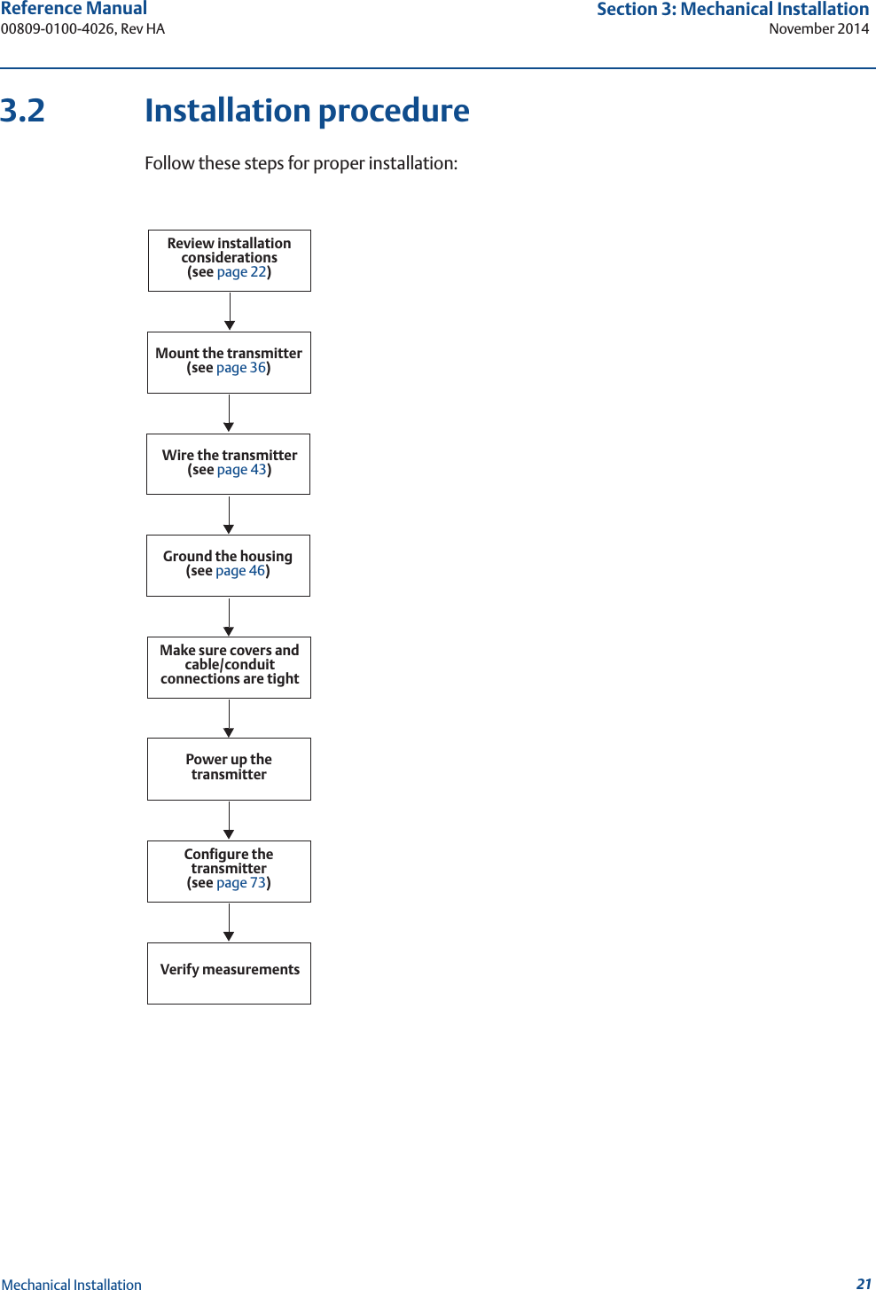
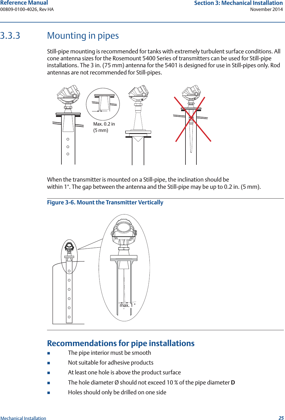
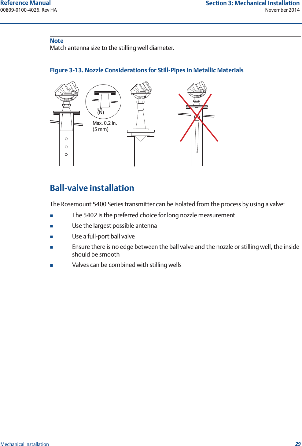
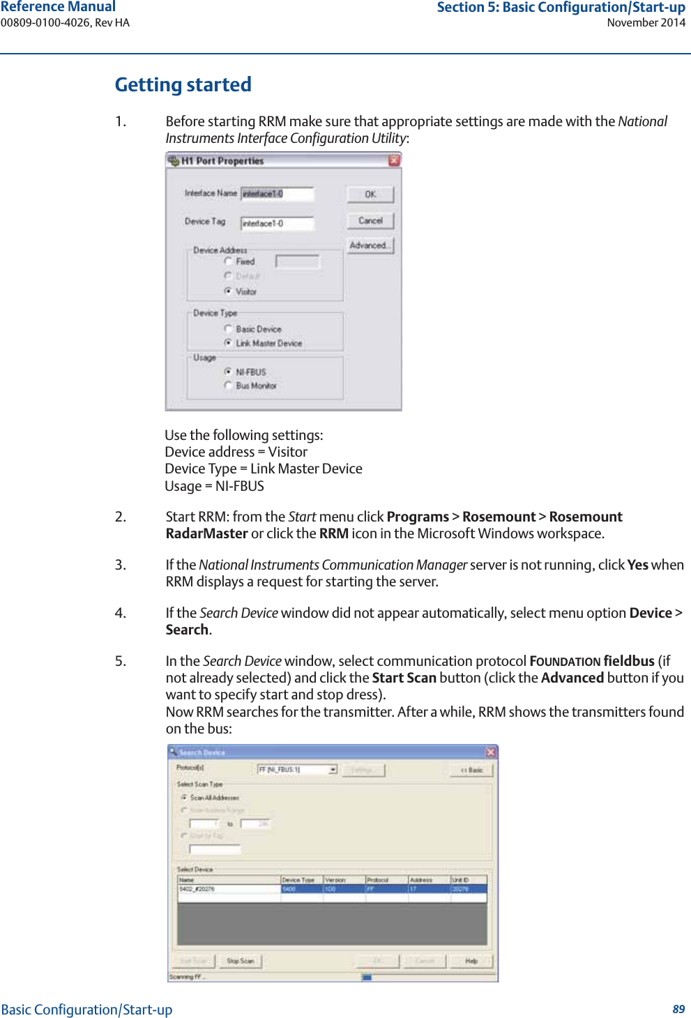
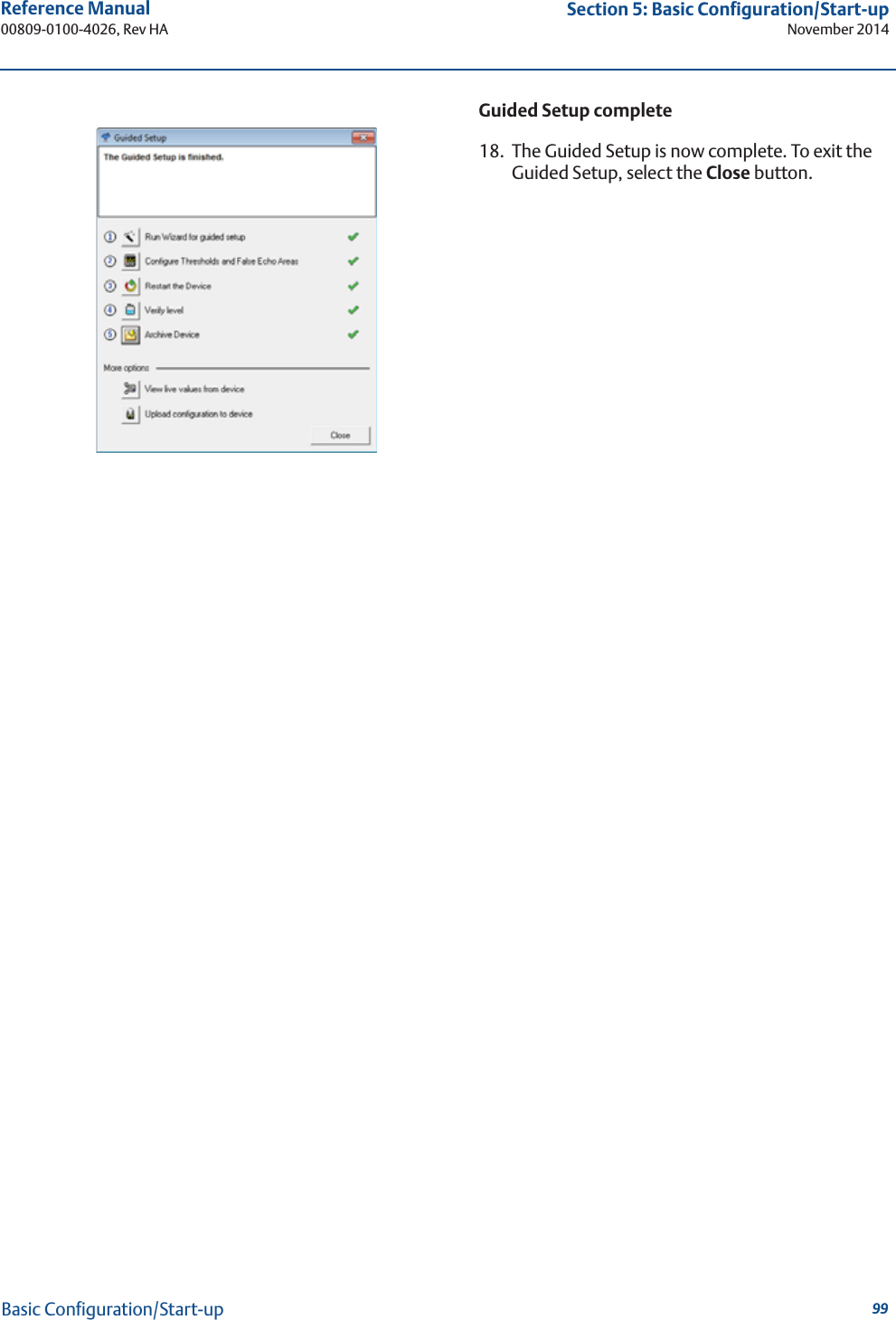
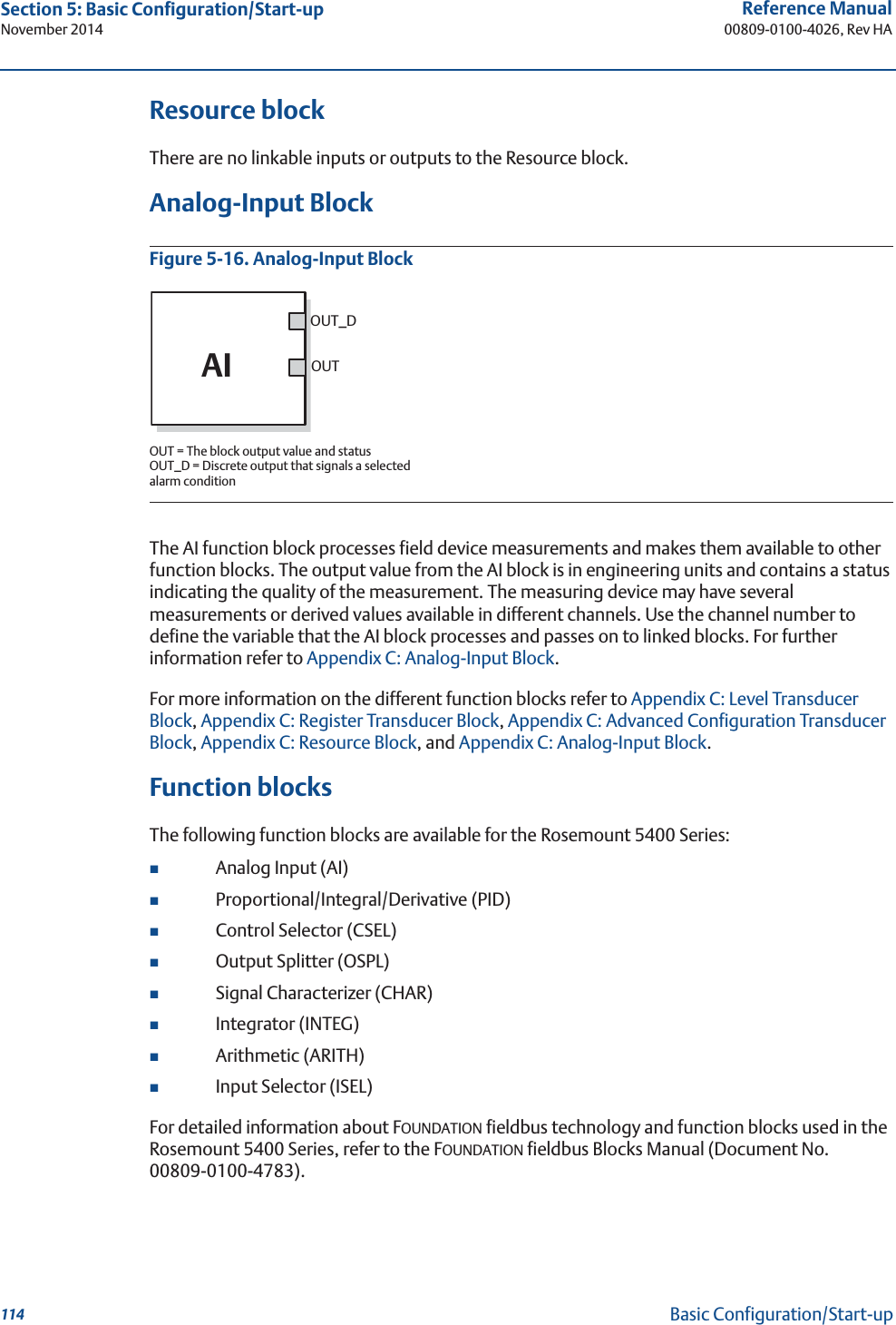
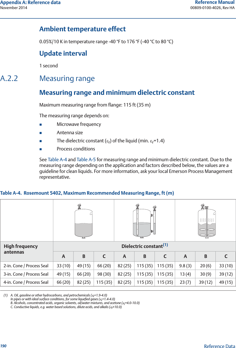
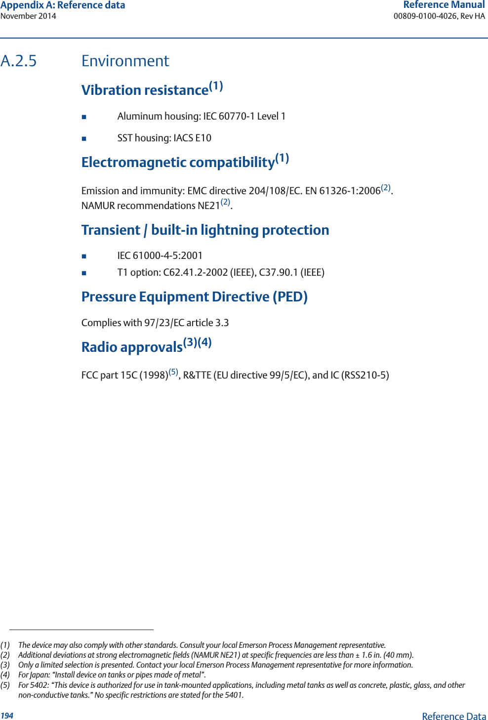
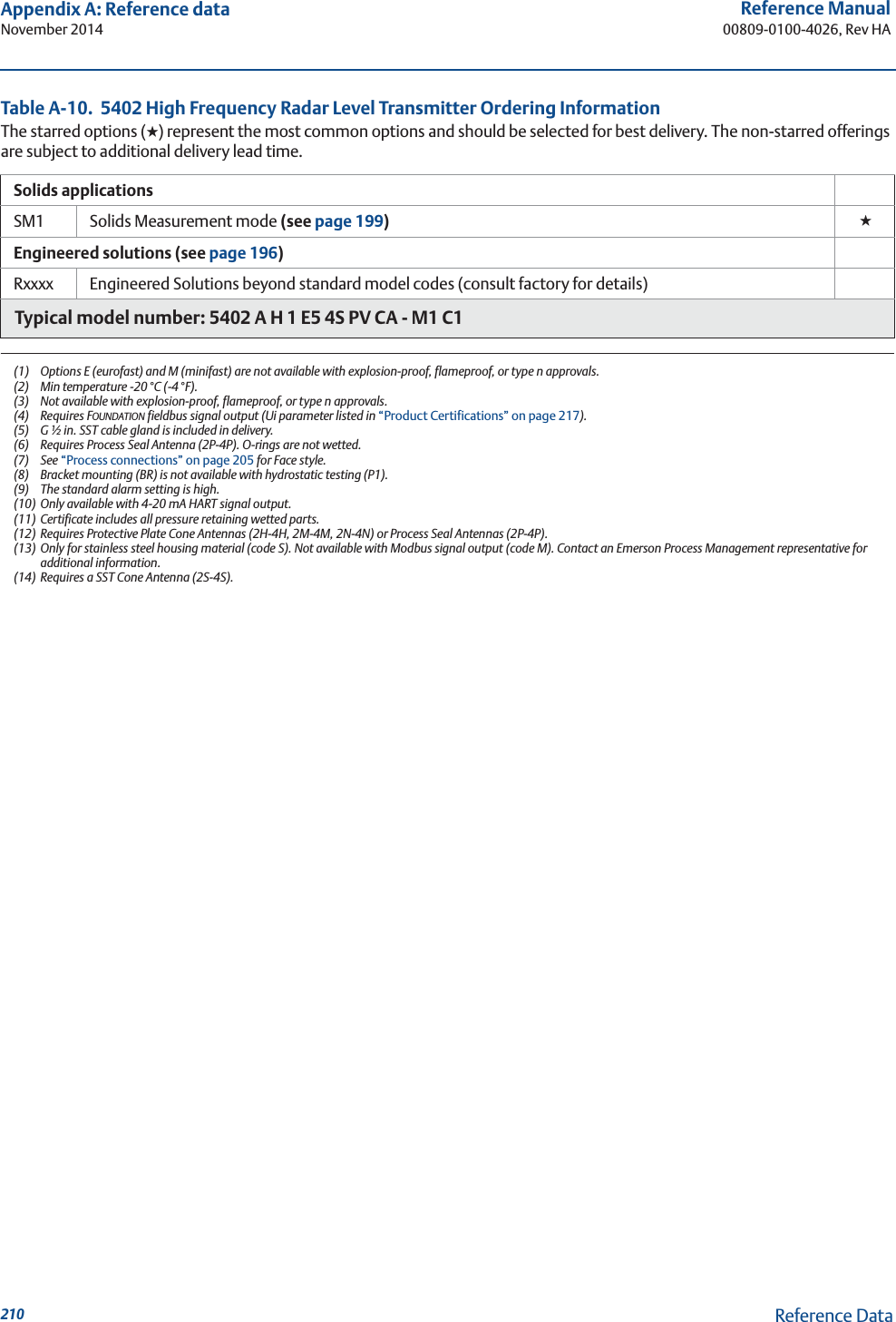
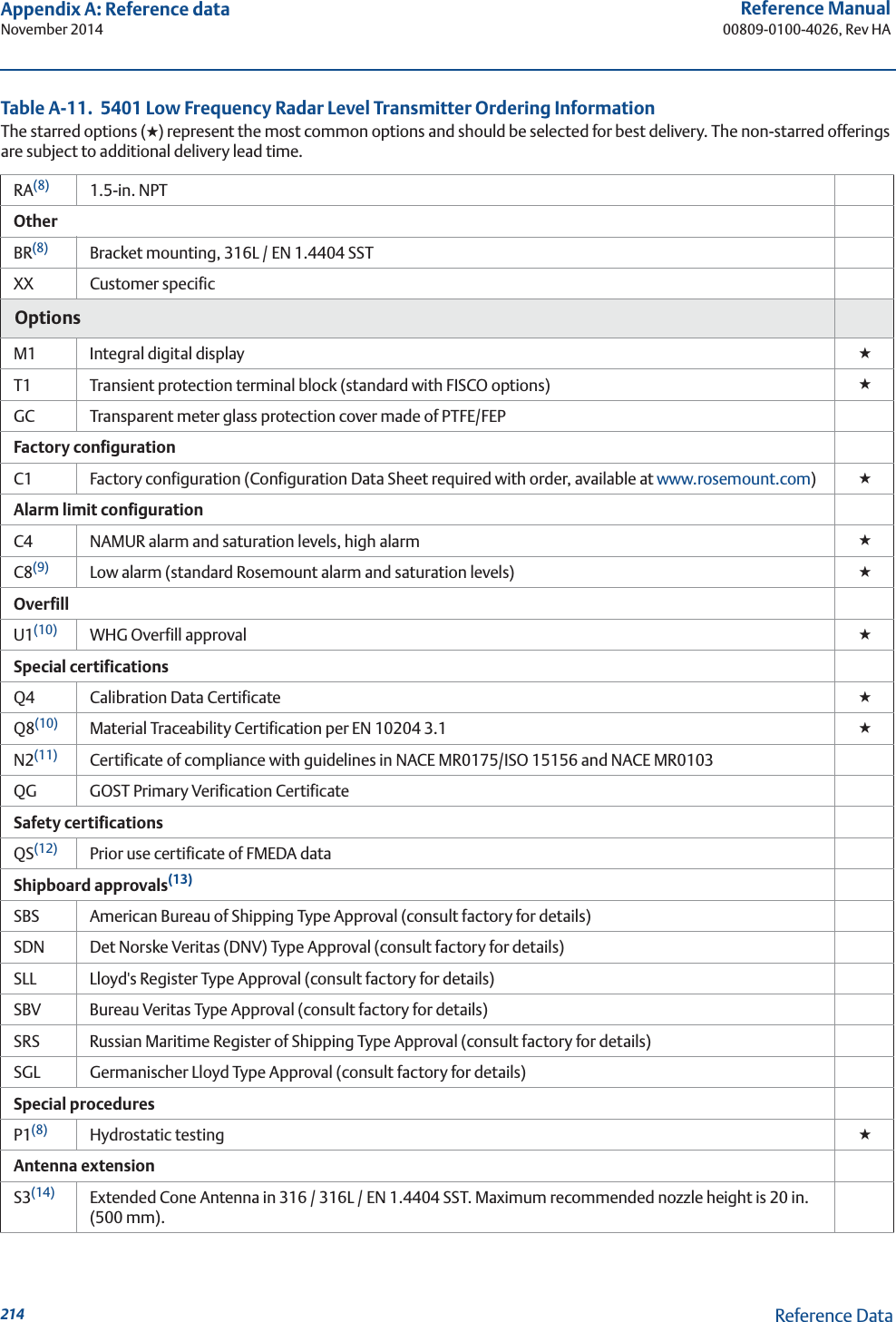
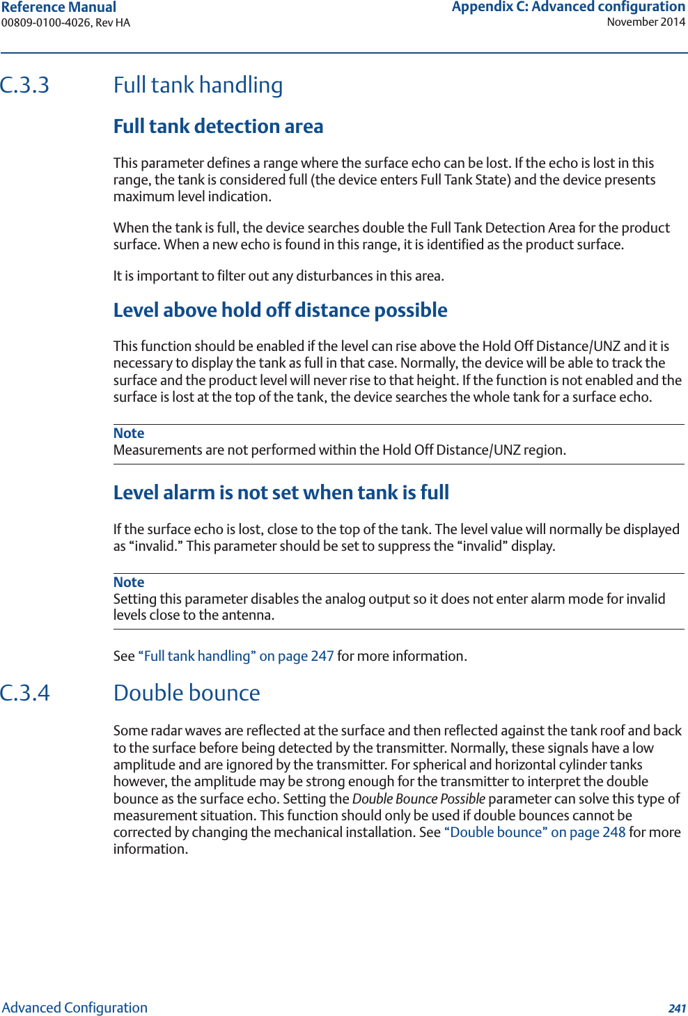
![83Reference Manual 00809-0100-4026, Rev HASection 5: Basic Configuration/Start-upNovember 2014Basic Configuration/Start-upDistance calibration1. Measure the actual distance between the Upper Reference Point and the product surface.2. Adjust the Calibration Distance so that the Distance measured by the transmitter corresponds to the actual distance. The Calibration Distance parameter is available via HART command [2, 3, 2, 4, 1],orRRM: a. Select the Tank icon under Device Config/Setup in the RRM workspace.b. In the Tank window, select the Geometry tab.c. Select the Advanced button.d. Enter the desired value in the Calibration Distance field and select the Store button.Level calibration1. Measure the actual Product Level.2. Adjust the Tank Height so the product level measured by the transmitter corresponds to the actual product level.Figure 5-7. Distance and Level Calibration5.3.7 Echo tuningWhen Basic Configuration is performed, the transmitter may need to be tuned to handle disturbing objects in the tank. There are different methods available for handling disturbance echoes with the Rosemount 5400 Series Transmitter:ATCFalse echo registration, see “Registration of false echoes” on page 135The Guided Setup in the RRM configuration program includes a Measure and Learn function which automatically registers false echoes and creates an ATC (see “Guided setup” on page 92).The created ATC is based on the present tank spectra and process condition settings. Disturbances below the product surface might not be handled by the Measure and Learn function.Reference pointDistanceReference pointTank heightLevel](https://usermanual.wiki/Rosemount-Tank-Radar/05402/User-Guide-2448693-Page-95.png)
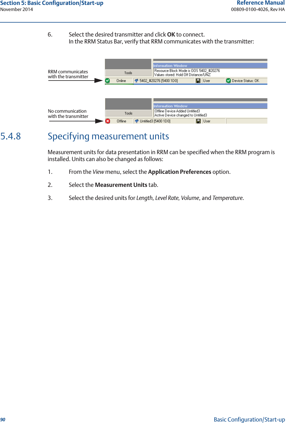
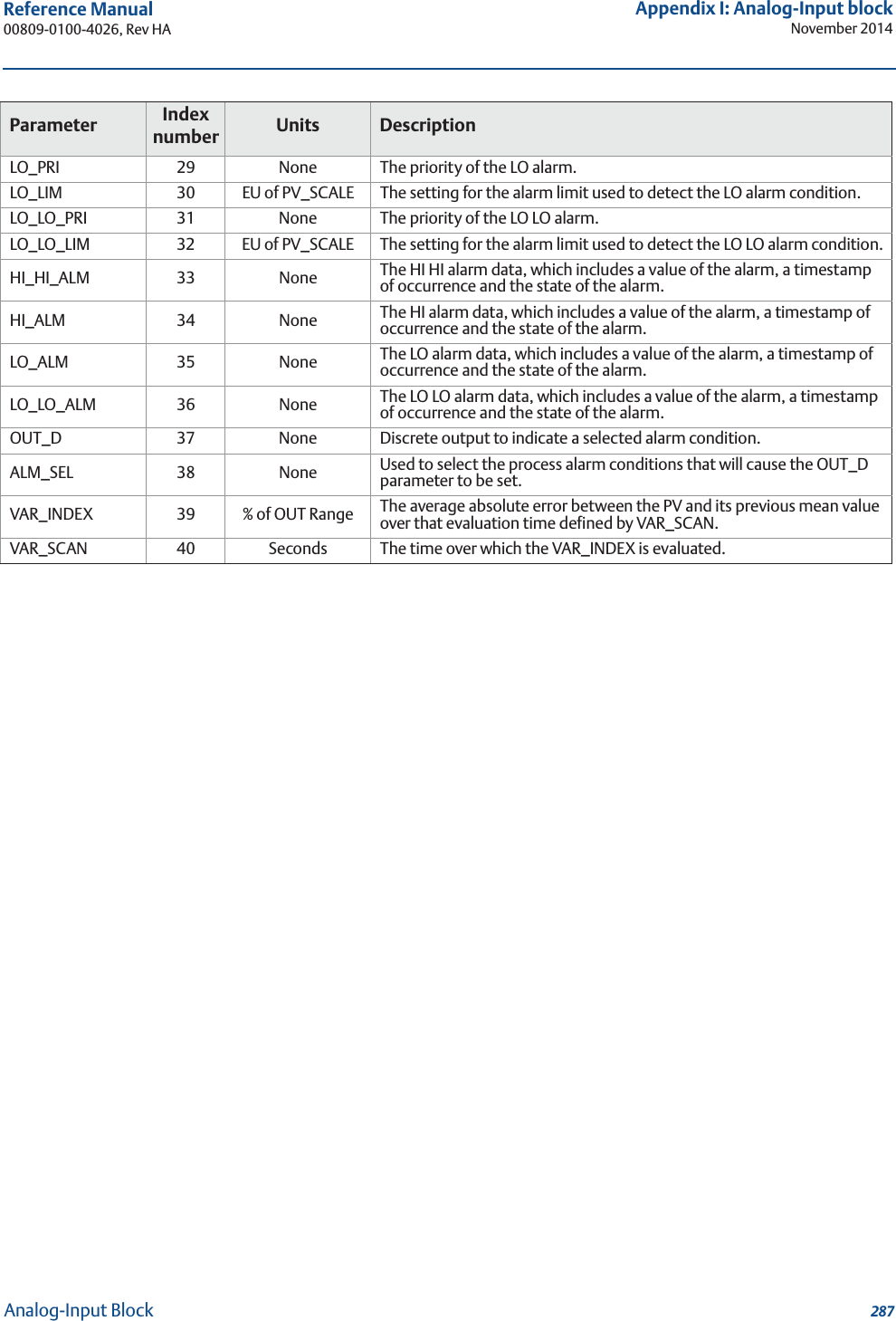
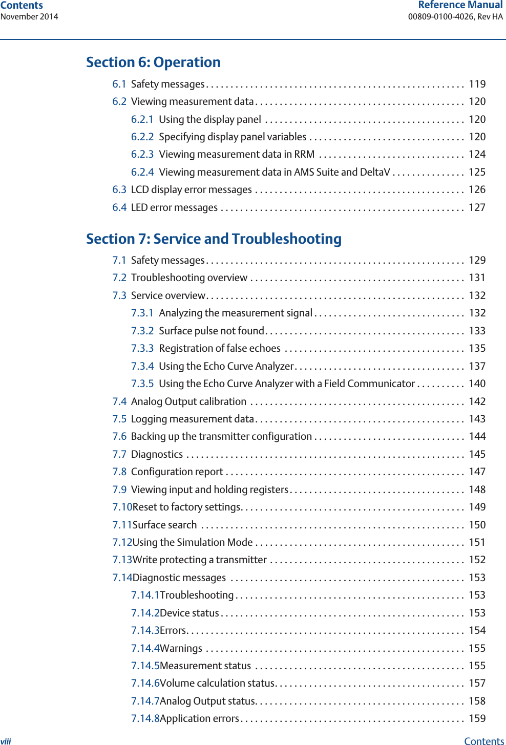
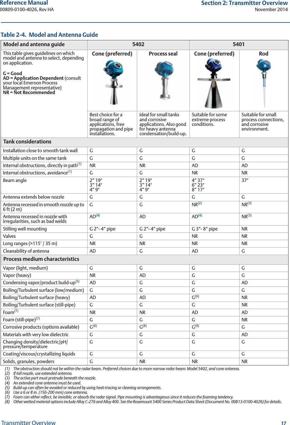
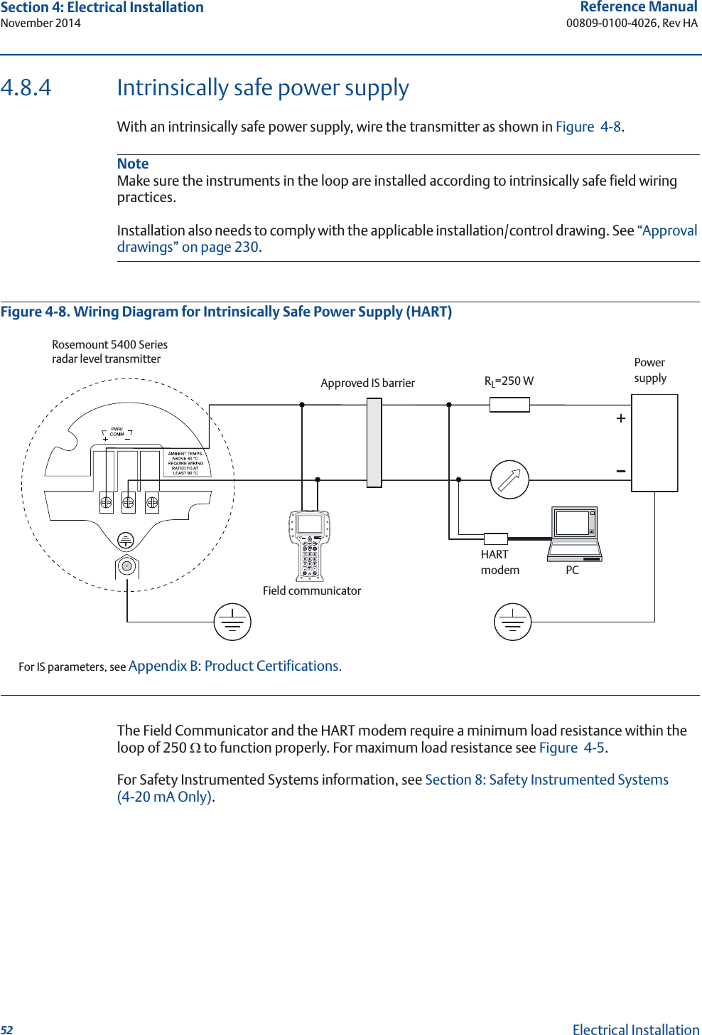
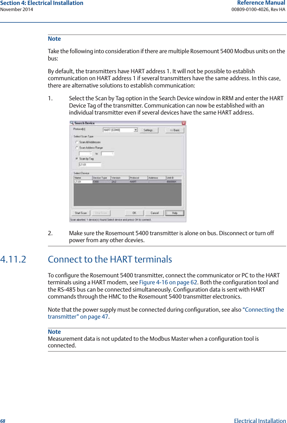
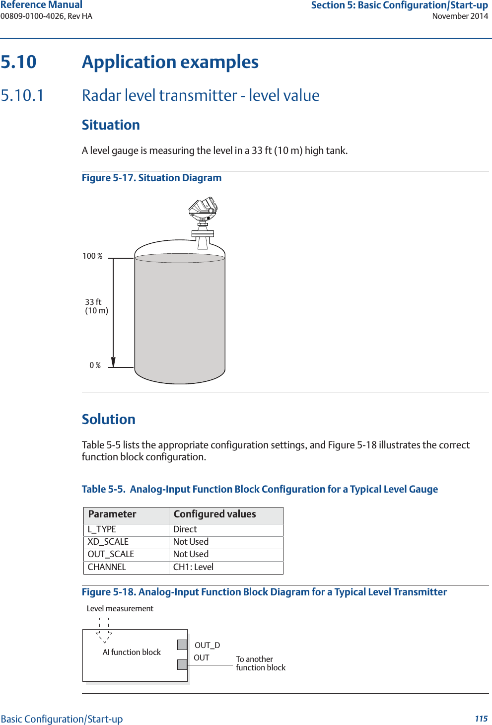
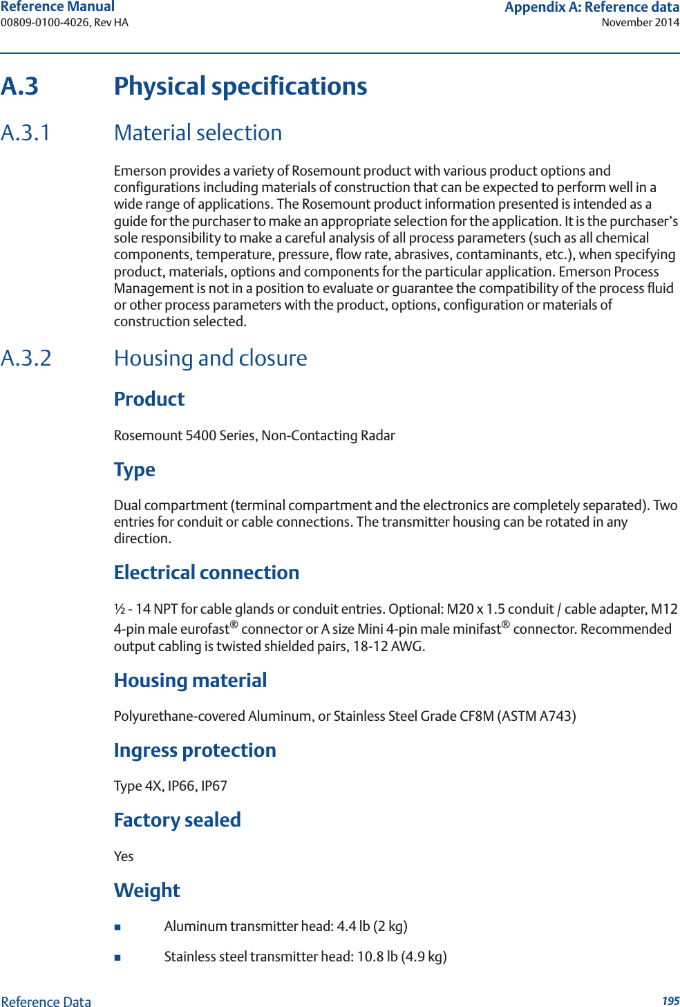
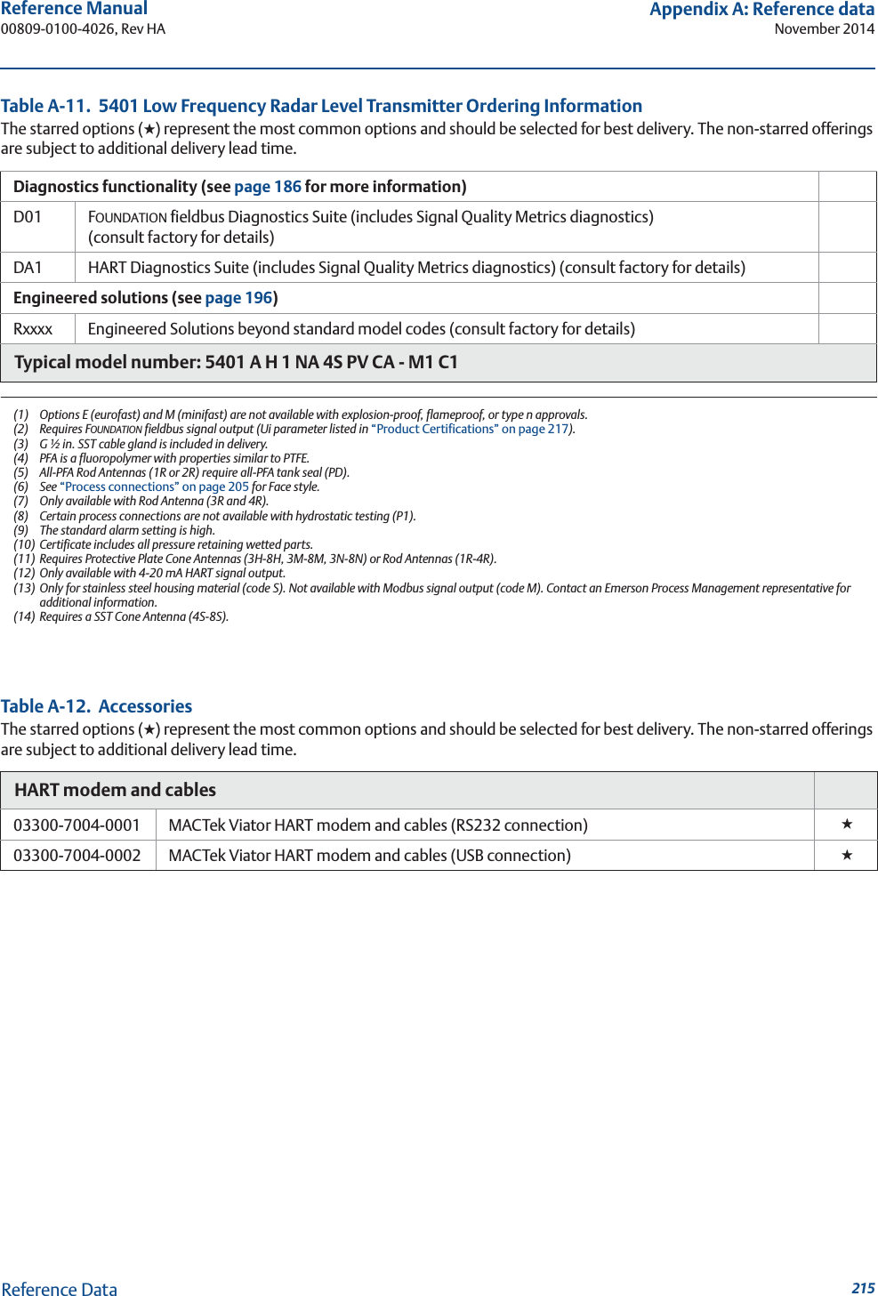
![93Reference Manual 00809-0100-4026, Rev HASection 5: Basic Configuration/Start-upNovember 2014Basic Configuration/Start-upDevice Information4. The Tag, Message, Descriptor, and Date information is entered in this window. This information is not required for the operation of the transmitter and may be left out, if desired.HART command: [2, 2, 1].Digital Units5. The Length Unit, Level Rate Unit, Volume Unit, and Temperature Unit information is entered in this window.](https://usermanual.wiki/Rosemount-Tank-Radar/05402/User-Guide-2448693-Page-105.png)
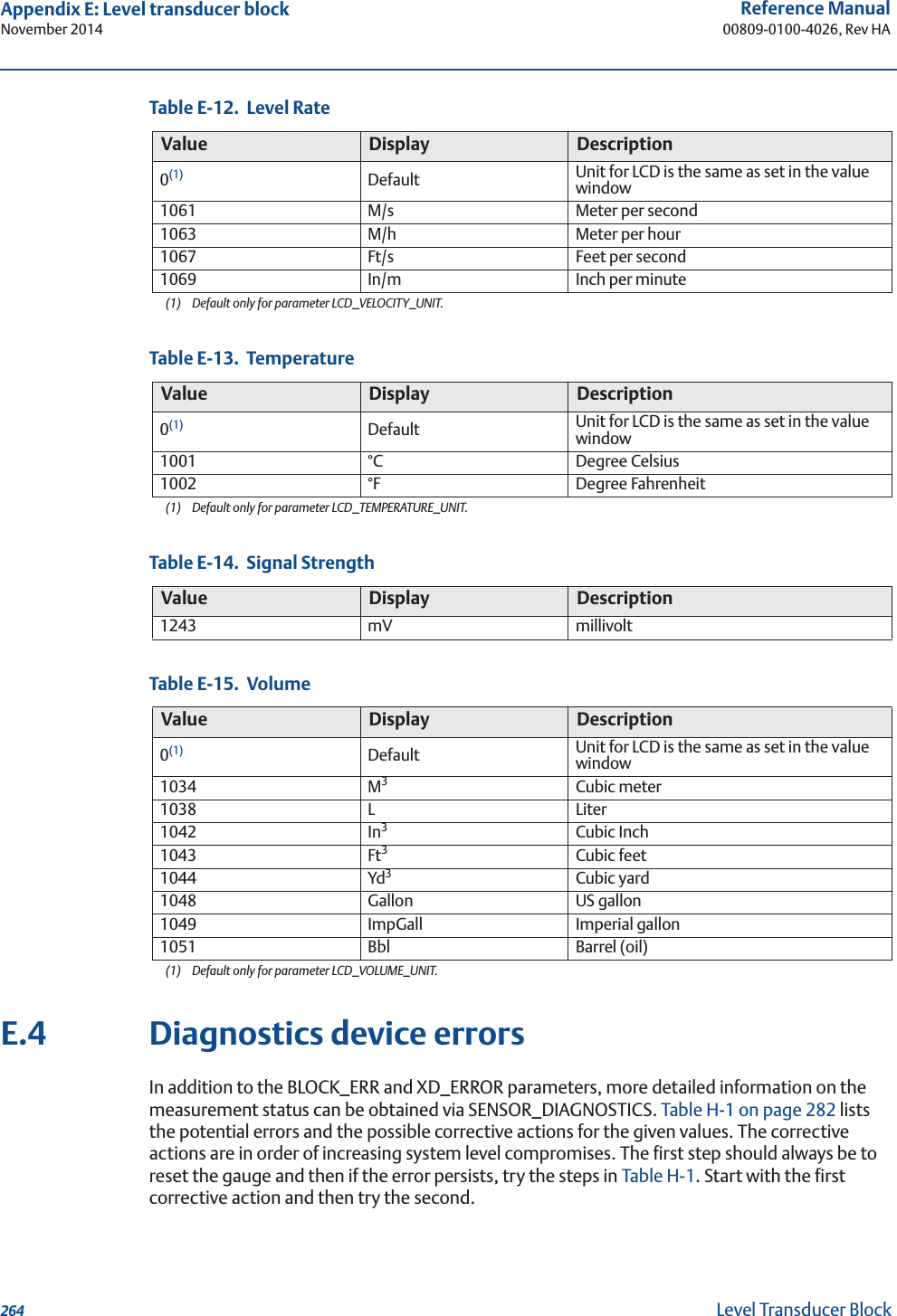
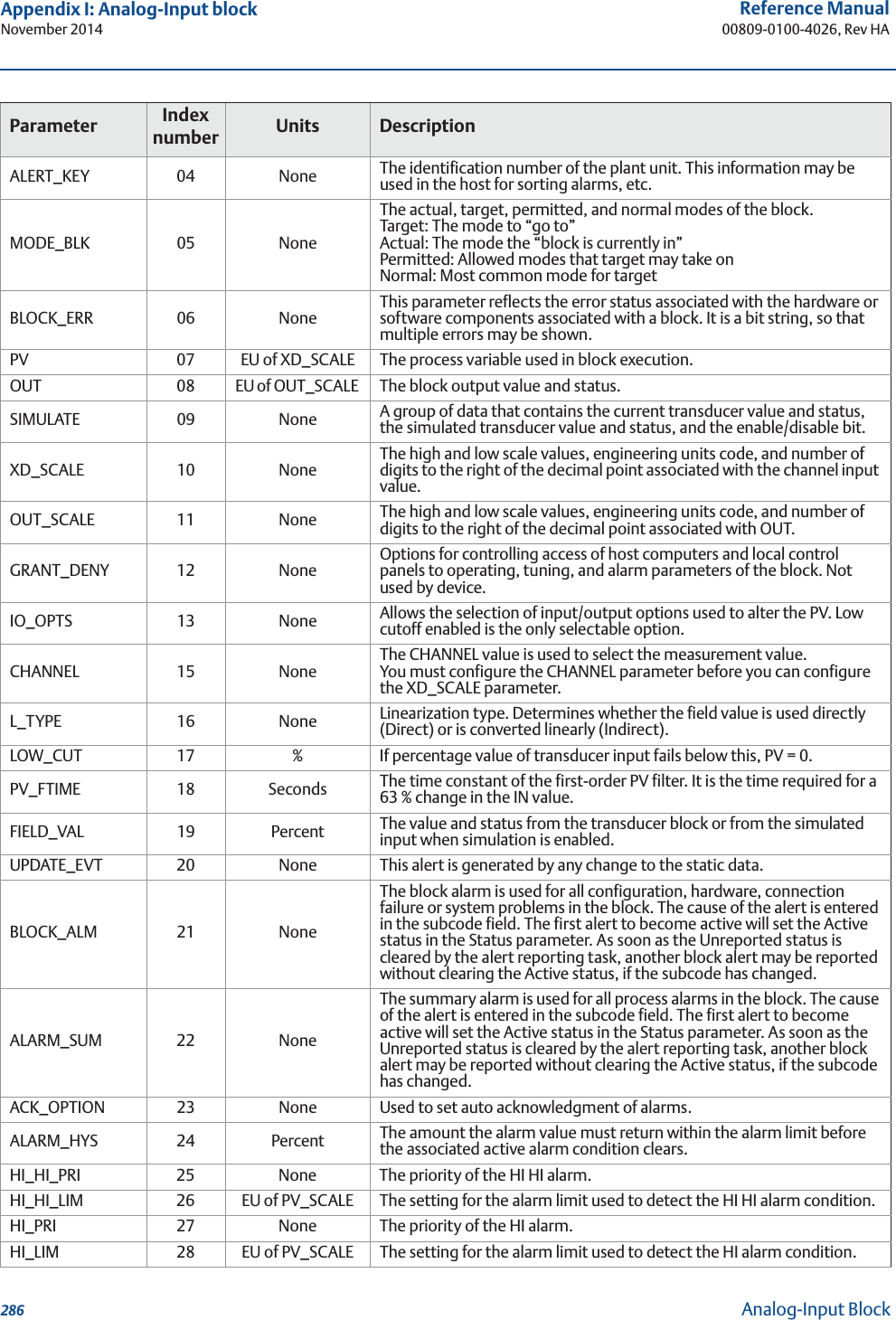
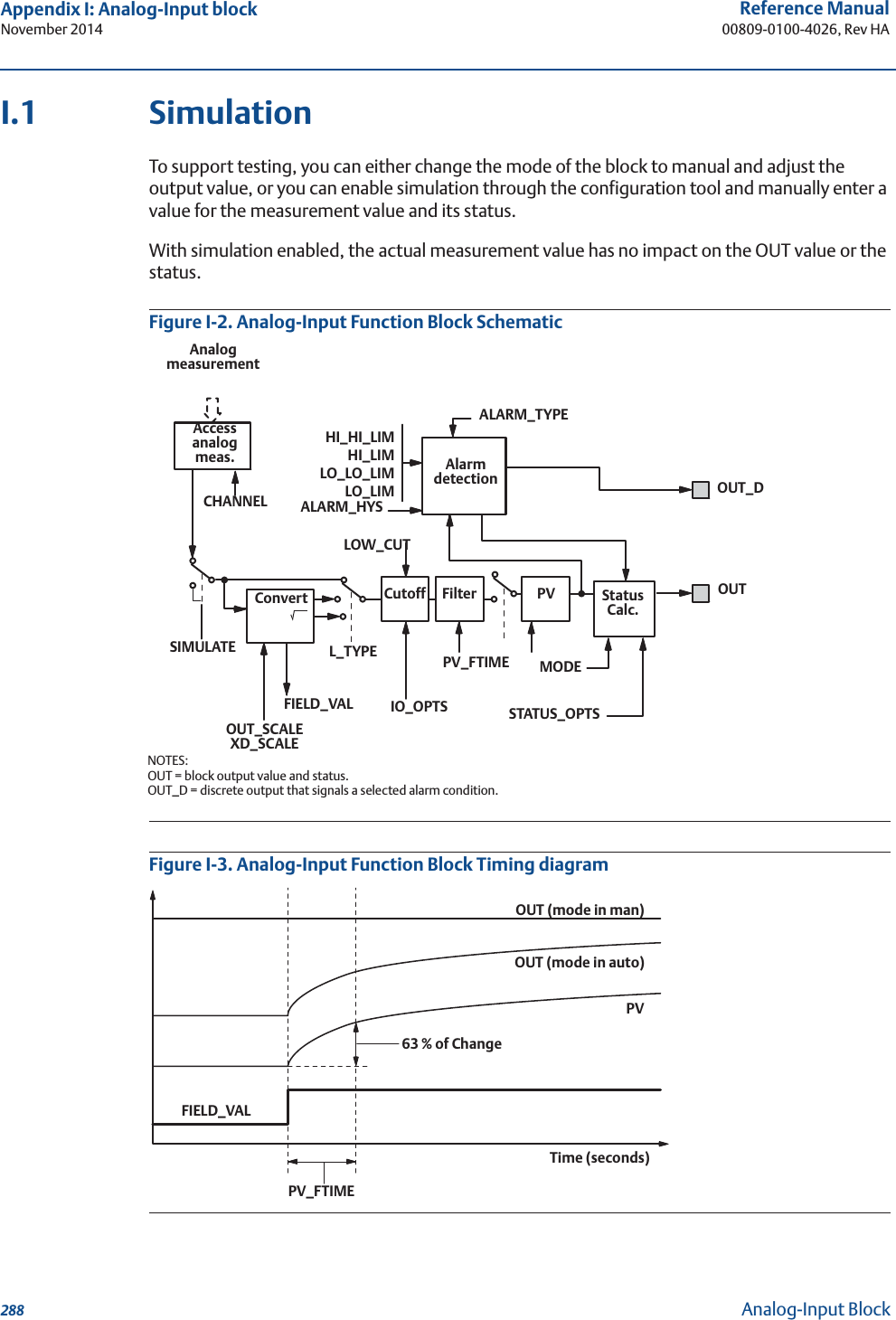
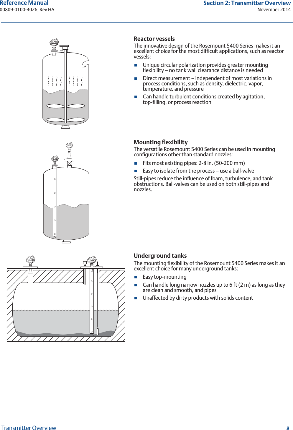
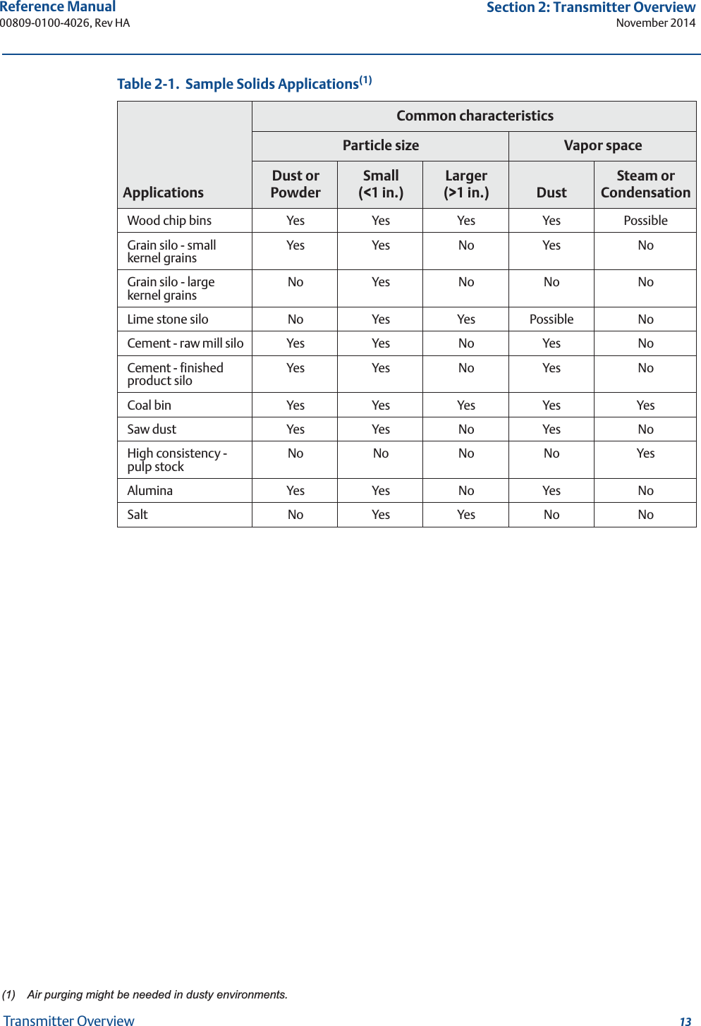
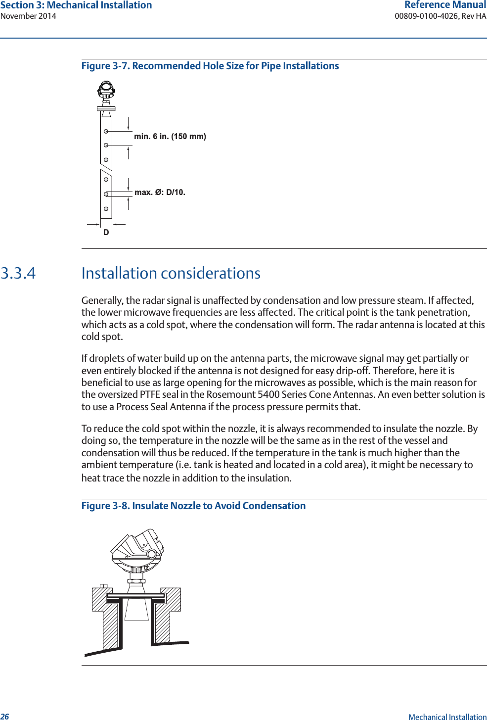
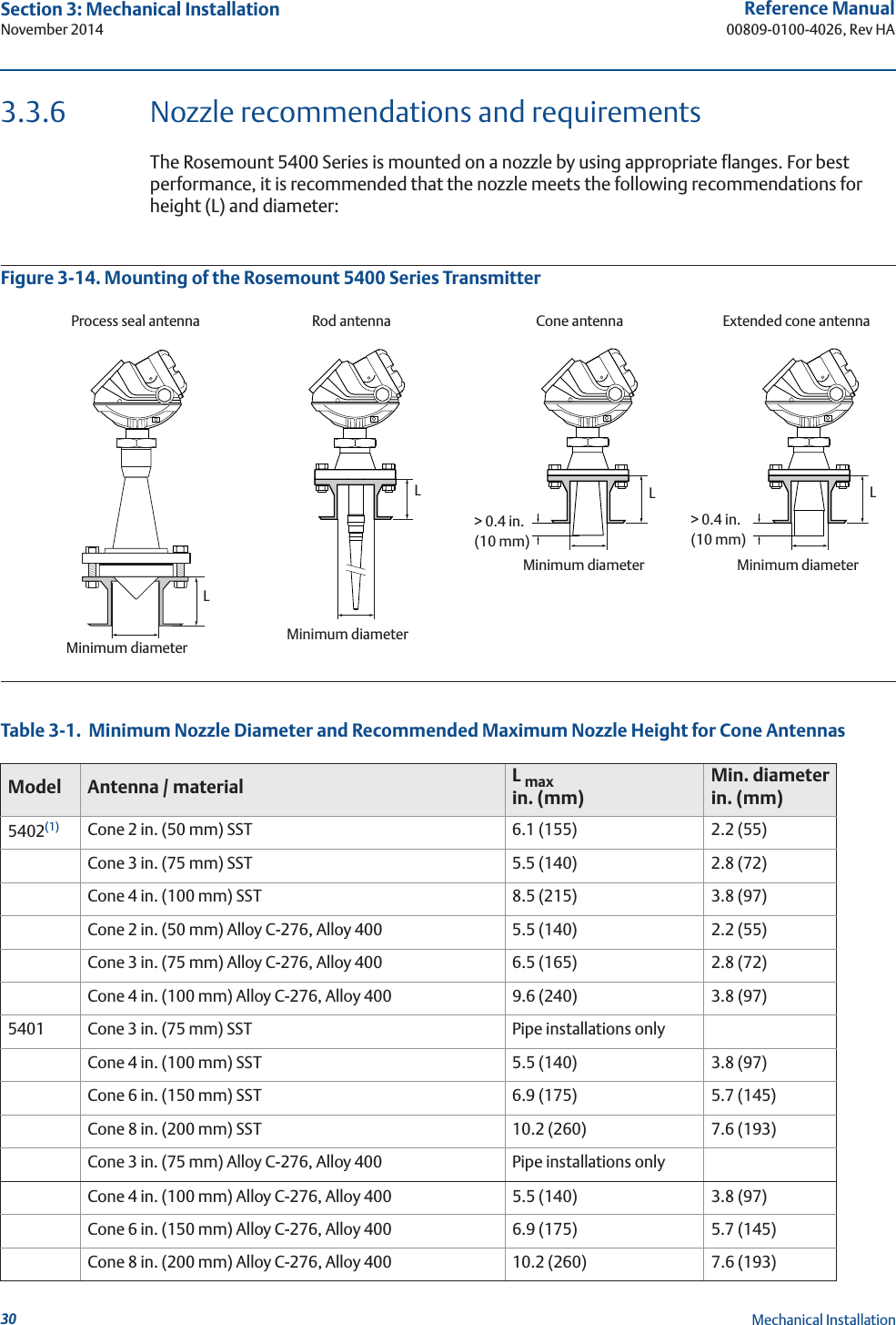
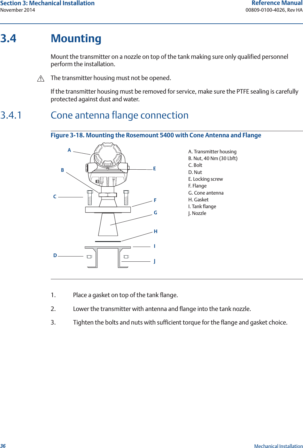
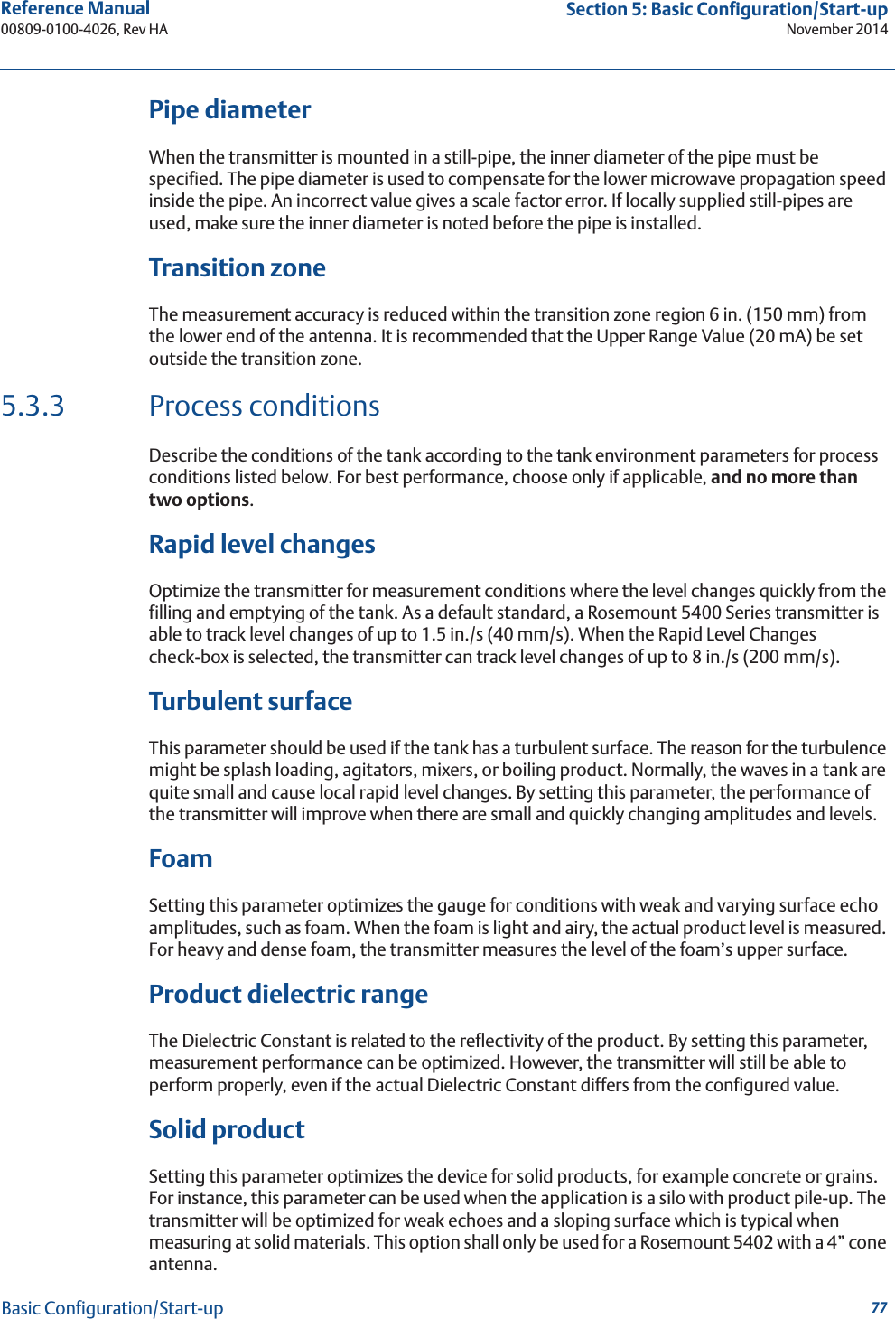
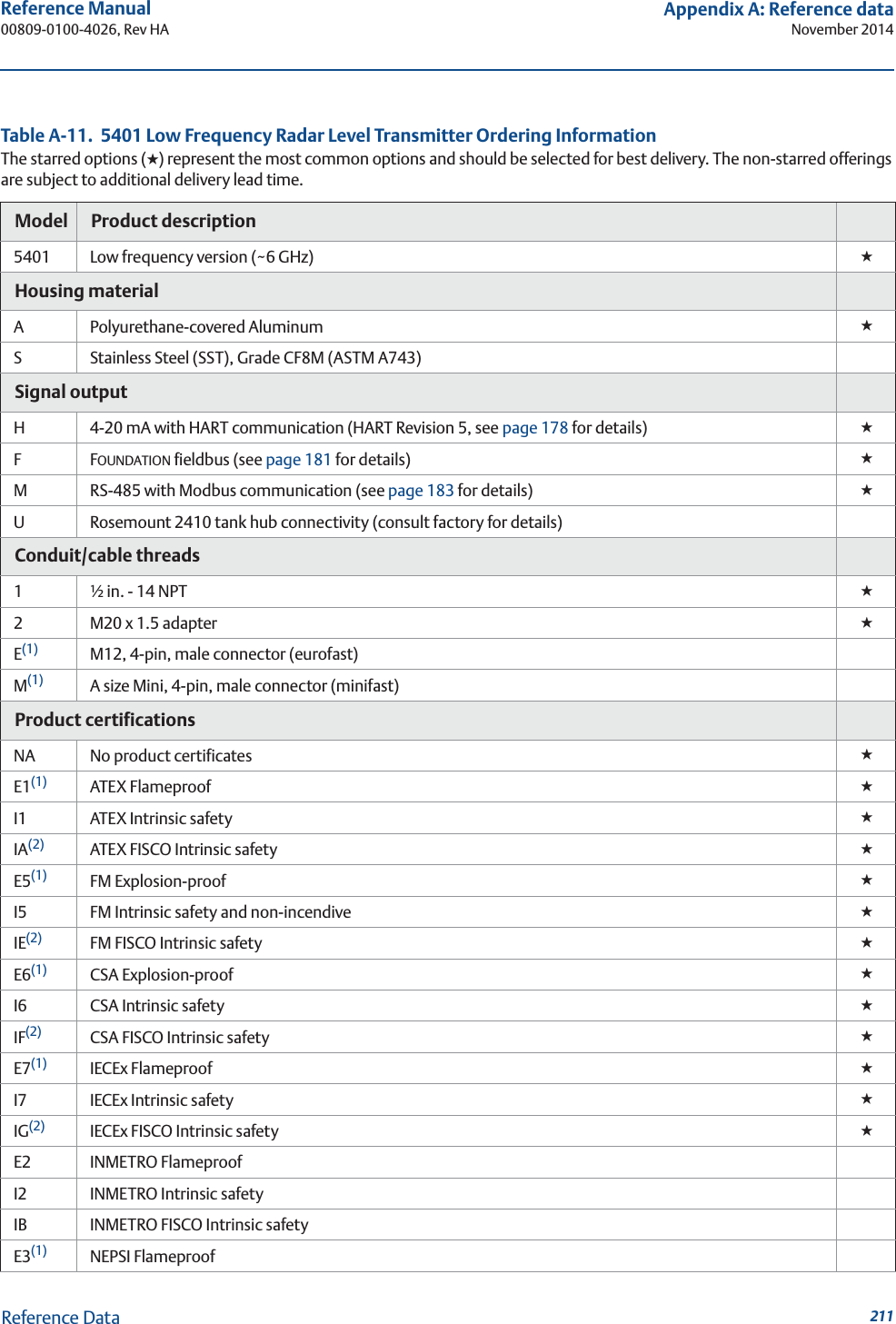
![94Reference Manual00809-0100-4026, Rev HASection 5: Basic Configuration/Start-upNovember 2014Basic Configuration/Start-upTank Geometry6. Select the Tank Type corresponding to the actual tank. If none of the available options matches the tank, select Unknown. HART command: [2, 1, 2, 1].FOUNDATION fieldbus parameter: TRANSDUCER_1100 > GEOM_TANK_TYPE.Tank Bottom Type is important for the measurement performance close to the tank bottom.HART command: [2, 1, 2, 2].FOUNDATION fieldbus parameter: TRANSDUCER_1100 > GEOM_TANK_BOTTOM_TYPE.Tank Height is the distance from the Upper Reference Point to the Lower Reference Point (see “Tank geometry” on page 75). This number needs to be as accurate as possible.HART command: [2, 1, 2, 3].FOUNDATION fieldbus parameter: TRANSDUCER_1100 > GEOM_TANK_HEIGHT.Select the Enable Still-Pipe/Bridle Measurement check-box and enter the Pipe Inner Diameter if the transmitter is mounted on a Still-Pipe. HART command: [2, 1, 2, 4] / [2, 1, 2, 5].FOUNDATION fieldbus parameter: TRANSDUCER_1100>SIGNAL_PROC_CONFIG (Enable), ANTENNA_PIPE_DIAM.For more information, see “Tank geometry” on page 75.Enable Still Pipe/Bridle Measurement](https://usermanual.wiki/Rosemount-Tank-Radar/05402/User-Guide-2448693-Page-106.png)
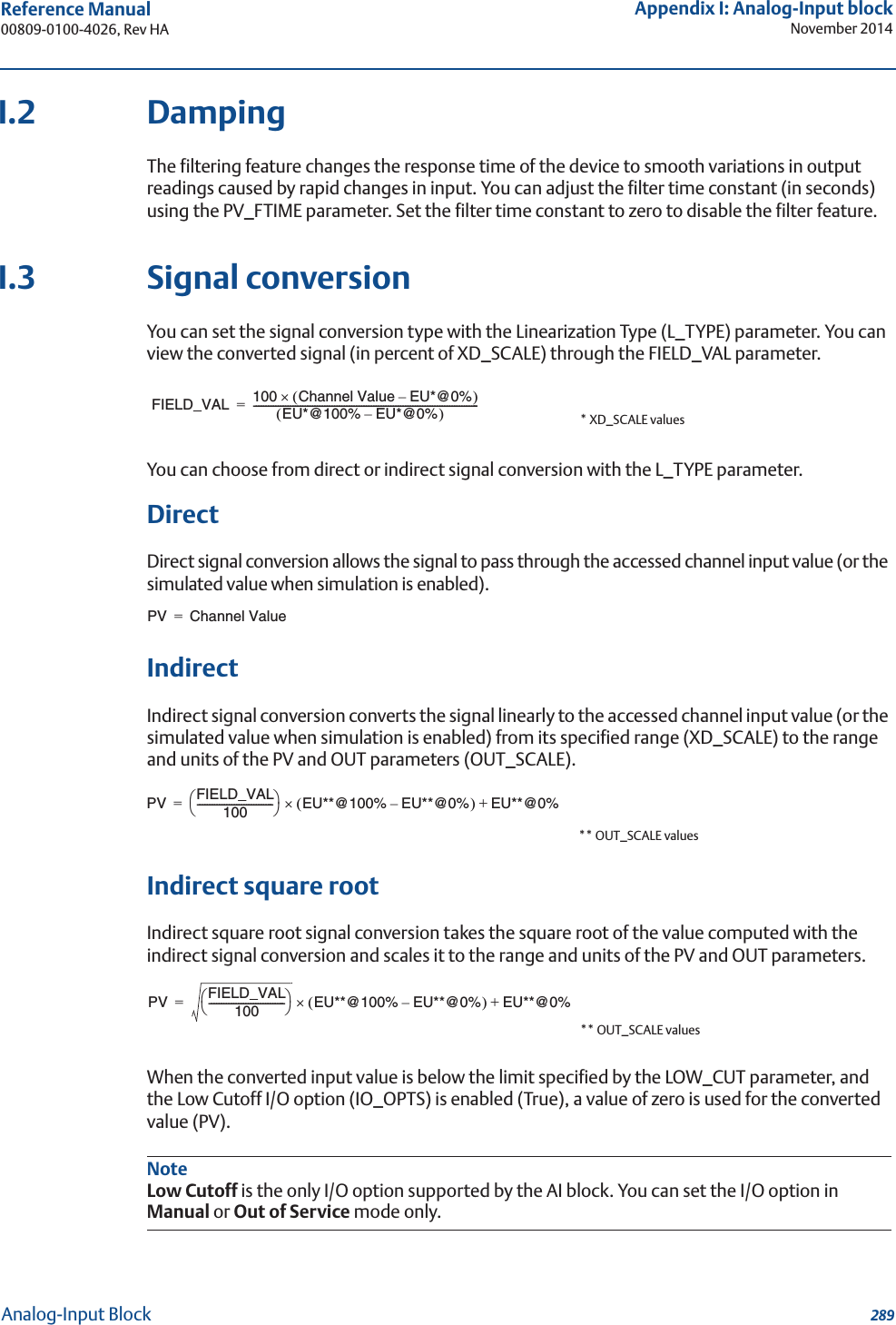
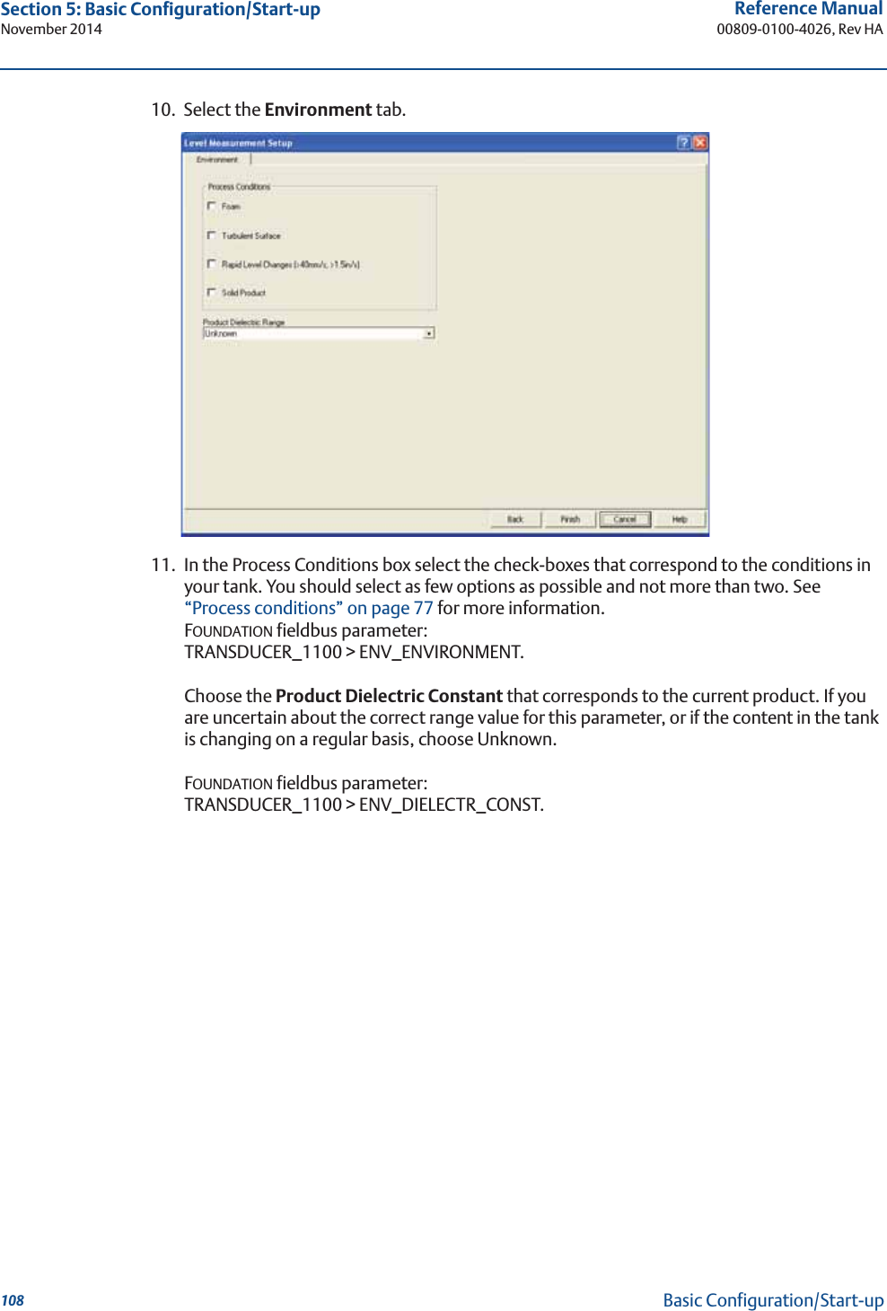
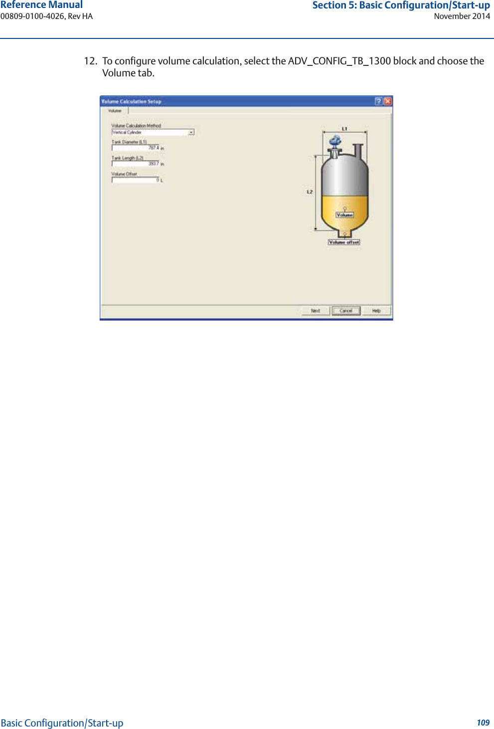
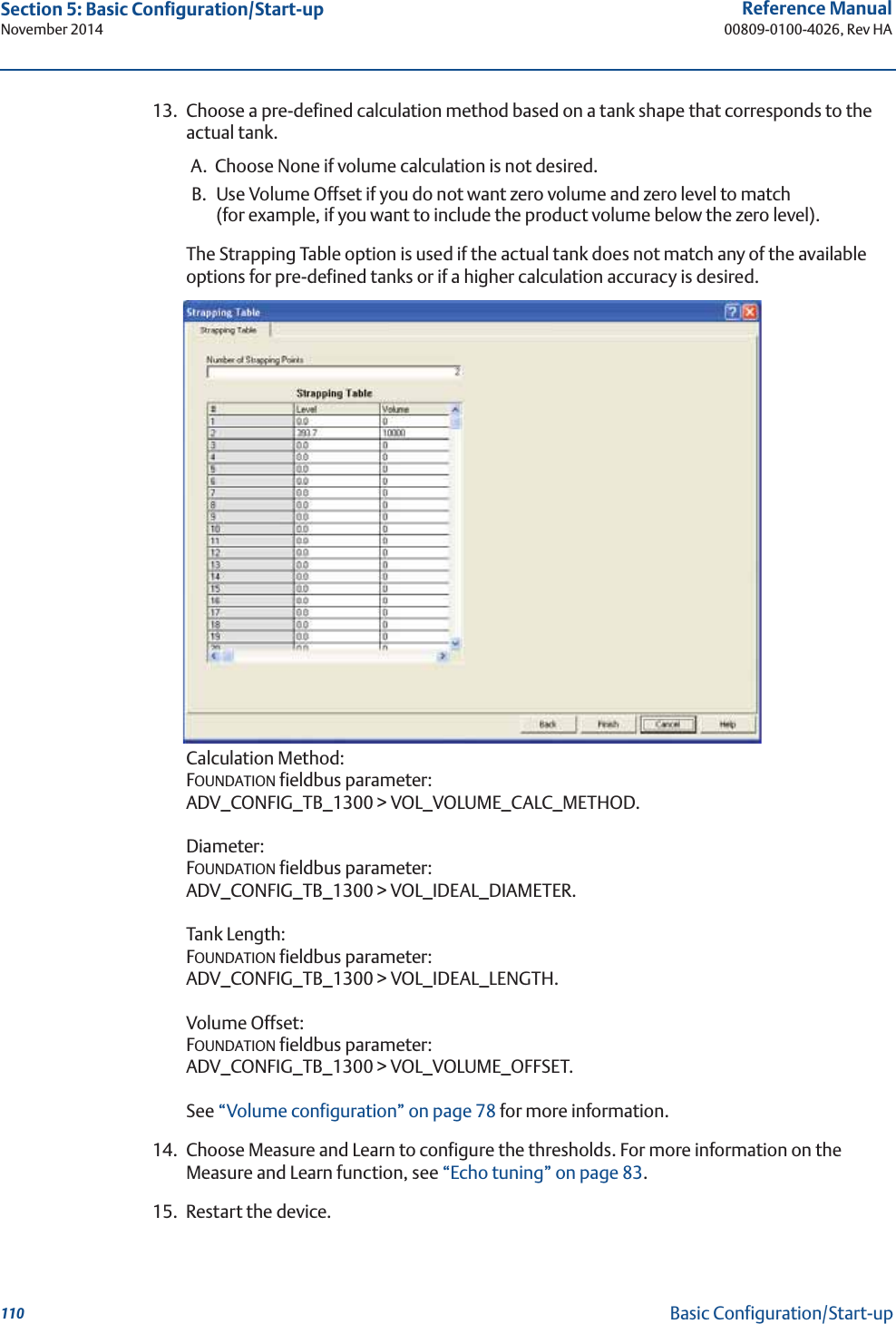
![95Reference Manual 00809-0100-4026, Rev HASection 5: Basic Configuration/Start-upNovember 2014Basic Configuration/Start-upTank Environment7. In the Process Condition box, select the check-boxes that correspond to the conditions of the tank. Select as few options as possible and no more than two. See “Process conditions” on page 77 for more information.FOUNDATION fieldbus parameter: TRANSDUCER_1100 > ENV_ENVIRONMENT.The Dielectric Chart lists the dielectric constants of a large number of products and can be opened by selecting View > Dielectric Constant Chart menu option.Select the Product Dielectric Range that corresponds to the current product. If the correct range value for this parameter is unknown, or the contents in the tank are continually changing, choose Unknown.HART command: [2, 1, 3, 2].FOUNDATION fieldbus parameter: TRANSDUCER_1100 > ENV_DIELECTR_CONST.Volume8. For volume calculation, select a pre-defined calculation method based on a tank shape that corresponds to the actual tank. Select None if volume calculation is not needed.The Strapping Table option is used if the actual tank does not match any of the available options for pre-defined tanks or if higher calculation accuracy is desired.HART command: [2, 1, 4, 1].FOUNDATION fieldbus parameters: ADV_CONFIG_TB_1300 >VOL_VOLUME_CALC_METHOD/VOL_IDEAL_DIAMETER/VOL_IDEAL_LENGTH/VOL_VOLUME_OFFSET.For more information, see “Volume configuration” on page 78.](https://usermanual.wiki/Rosemount-Tank-Radar/05402/User-Guide-2448693-Page-107.png)
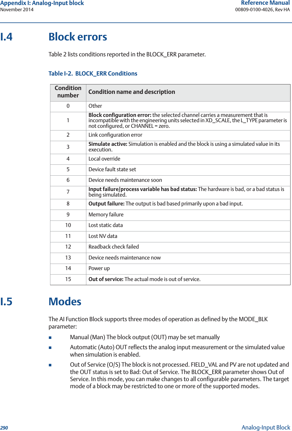
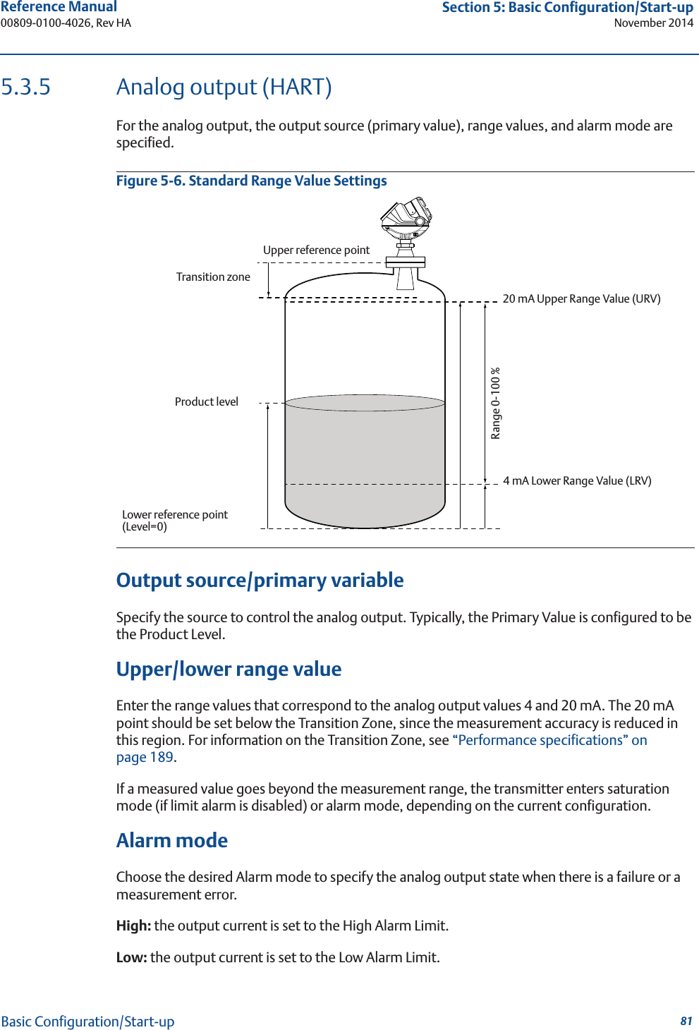
![96Reference Manual00809-0100-4026, Rev HASection 5: Basic Configuration/Start-upNovember 2014Basic Configuration/Start-upAnalog output9. Typically, the Primary Variable (PV) is configured to be Product Level or Volume.Set the analog output range by inputting the Lower Range Value (4 mA) and the Upper Range Value (20 mA) to the desired values. The Alarm Mode specifies the output state when a measurement error occurs.HART command: [2, 1, 5].See “Analog output (HART)” on page 81 for more information on Analog Output configuration and Alarm Mode settings.Finish Configuration Wizard10. This is the last window in the Configuration Wizard. The configuration can be changed at any time by using the Setup windows (General, Tank, Output etc., see “Using the Setup functions” on page 100), which contain further options not available in the configuration wizard.Select the Finish button and continue with the next step in the Guided Setup.Echo tuning11. Step 2 in the Guided Setup allows automatic configuration of the ATC and registration of false echoes by running the Measure and Learn function. See “Echo tuning” on page 83 for more information on amplitude thresholds and false echoes.Click button 2 to start the Measure and Learn function.(If Echo Tuning is not needed, or is done at a later stage, go on to step 3 in the Guided Setup).](https://usermanual.wiki/Rosemount-Tank-Radar/05402/User-Guide-2448693-Page-108.png)
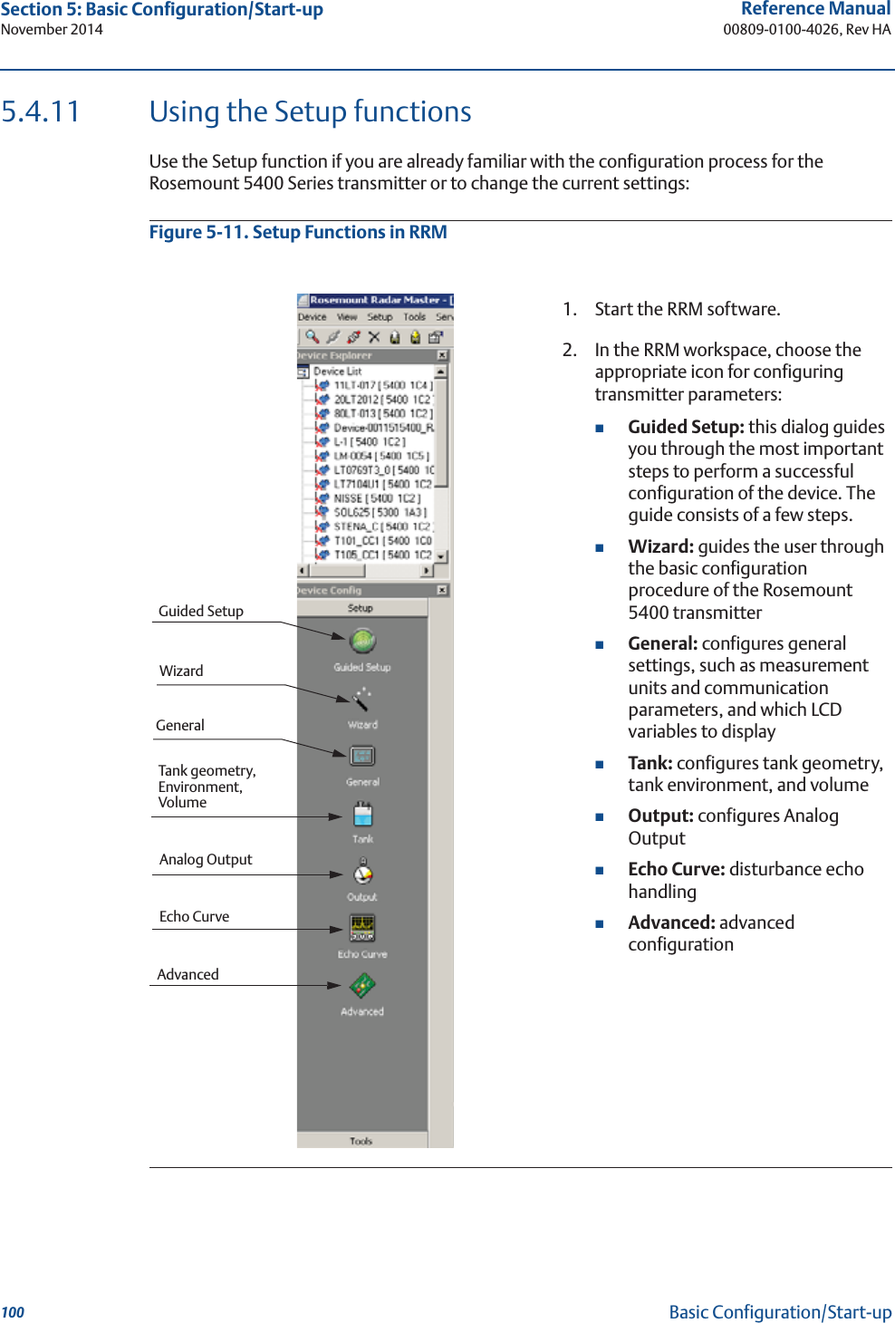
![102Reference Manual00809-0100-4026, Rev HASection 5: Basic Configuration/Start-upNovember 2014Basic Configuration/Start-upTo make a basic setup of the transmitter, do the following:1. Check that the desired Measurement Units are selected. HART command: [2, 1, 1, 5].2. Enter configuration parameters for the following:Device info. HART command: [2, 2, 1]Geometry. HART command: [2, 1, 2]Environment. HART command: [2, 1, 3]Volume. HART command: [2, 1, 4]Analog Out. HART command: [2, 1, 5]3. Run Measure and Learn. HART command: [2, 1, 6, 2]. This function creates an ATC.4. Restart the transmitter. HART command: [2, 1, 6, 4].To view the Echo Curve and adjust threshold settings, see “Using the Echo Curve Analyzer” on page 137.](https://usermanual.wiki/Rosemount-Tank-Radar/05402/User-Guide-2448693-Page-114.png)
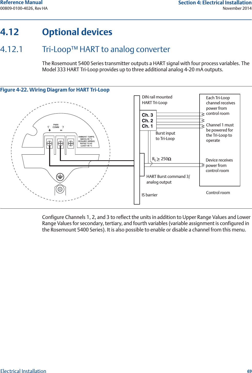
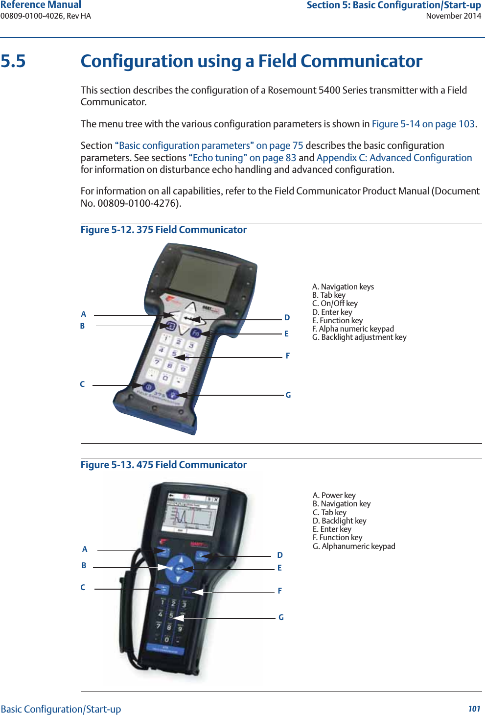
![117Reference Manual 00809-0100-4026, Rev HASection 5: Basic Configuration/Start-upNovember 2014Basic Configuration/Start-up5.11 Tri-Loop™ HART to Analog ConverterThe Rosemount 333 HART Tri-Loop HART-to-Analog Signal Converter is capable of converting a digital HART burst signal into three additional 4-20 mA analog signals. To set the Rosemount 5400 Series transmitter up for the HART Tri-Loop:1. Make sure the Rosemount 5400 transmitter is properly configured.2. Assign transmitter variables Primary Variable, Secondary Variable etc.HART command [2, 1, 1].RRM: Setup > Output/General.3. Configure variable units: Length, Level Rate, Volume, and Temperature. HART command [2, 2, 2, 5].RRM: Setup > General/Units.4. Set the Rosemount 5400 in Burst mode.HART command [2, 2, 4, 2].RRM: Setup > General/Communication.Variables AssignmentVariable Units](https://usermanual.wiki/Rosemount-Tank-Radar/05402/User-Guide-2448693-Page-129.png)
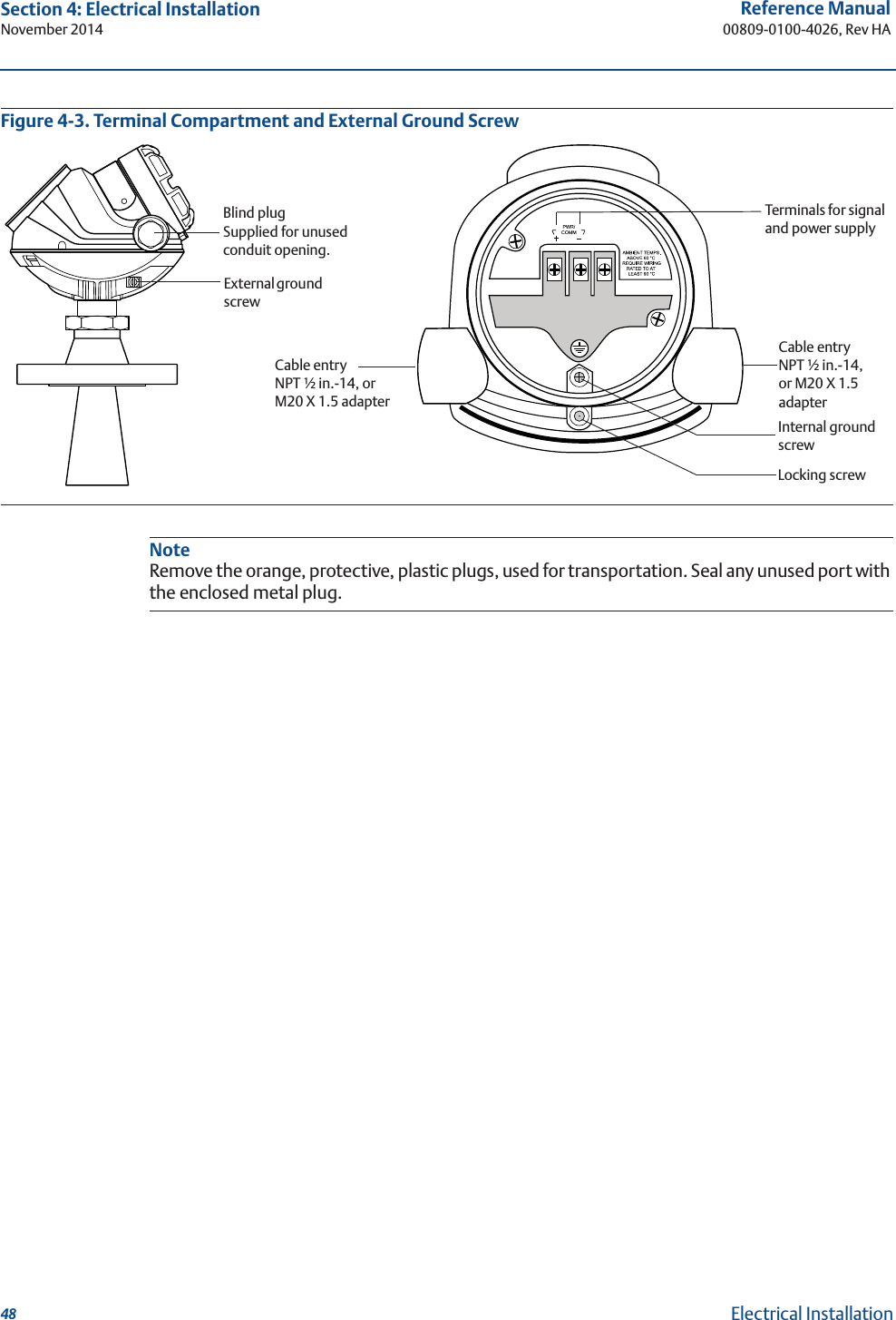
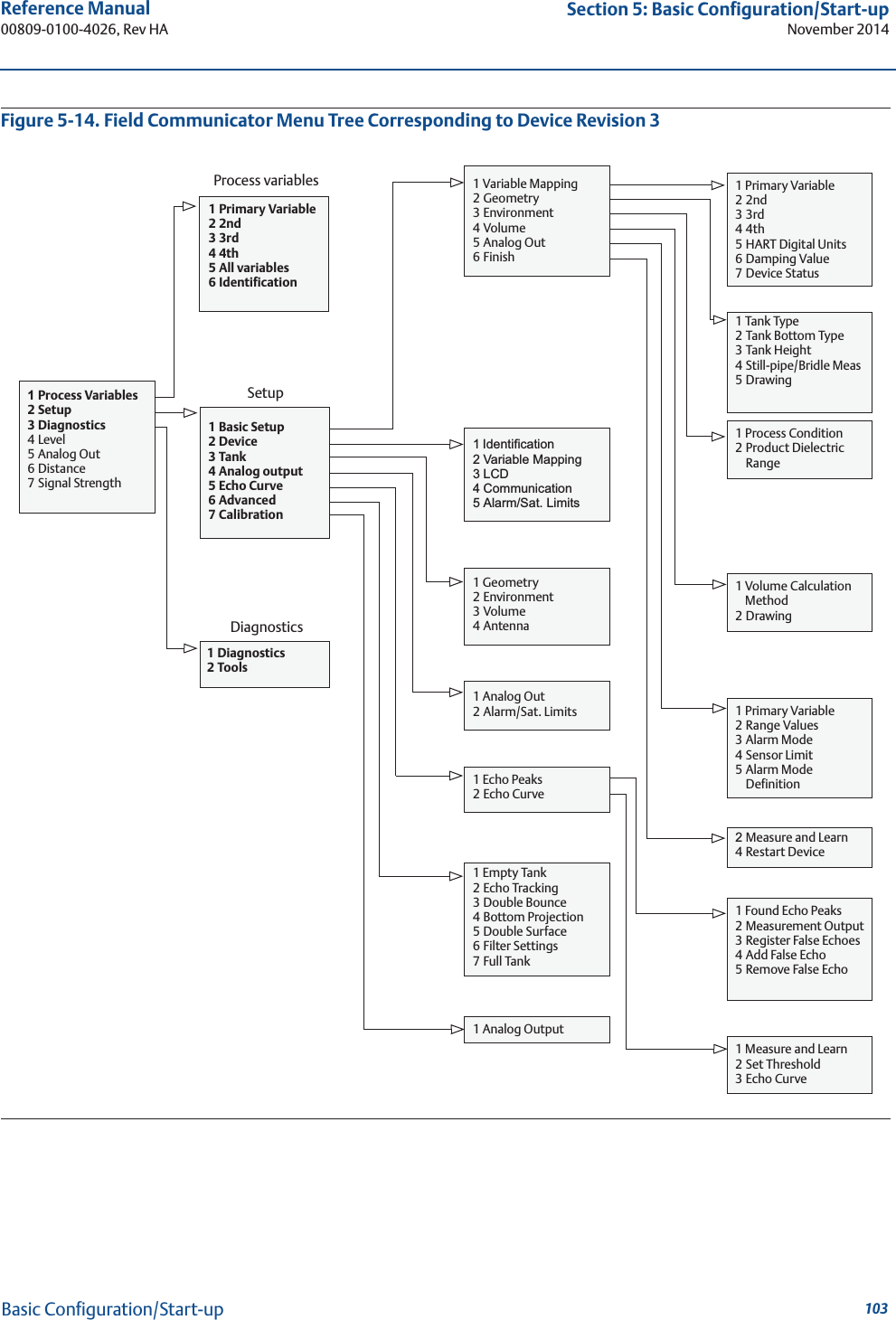
![118Reference Manual00809-0100-4026, Rev HASection 5: Basic Configuration/Start-upNovember 2014Basic Configuration/Start-up5. Select Burst option 3 = Process variables and current (Process vars/crnt).HART command [2, 2, 4, 2, 2].6. Install the Tri-Loop. Connect Channel 1 wires, and optionally wires for Channel 2 and Channel 3.7. Configure Tri-Loop Channel 1:a. Assign variable: Tri-Loop HART command [1, 2, 2, 1, 1].Make sure that the SV, TV, and QV match the configuration of the Rosemount 5400 Series transmitter.b. Assign units: Tri-Loop HART command [1, 2, 2, 1, 2]. Make sure that the same units are used as for the Rosemount 5400 Series transmitter.c. Set the Upper Range Value and the Lower Range Value: Tri-Loop HART command [1, 2, 2, 1, 3-4].d. Enable the channel. Tri-Loop HART command [1, 2, 2, 1, 5].8. (Optional) Repeat steps a-d for Channels 2 and 3.9. Connect wires to Tri-Loop Burst Input.10. Enter the desired tag, descriptor, and message information:Tri-Loop HART command [1,2,3].11. (Optional) If necessary, perform an analog output trim for Channel 1 (and Channel 2 and 3 if they are used).Tri-Loop HART command [1, 1, 4].Figure 5-21. Tri-Loop WiringSee the reference manual for the Rosemount 333 HART Tri-Loop HART-to-Analog Signal Converter (Document No. 00809-0100-4754) for further information on how to install and configure the Tri-Loop.Each Tri-Loop Channel receives power from Control RoomChannel 1 must be powered for the Tri-Loop to operateDevice receives power from Control RoomHART Burst Command 3/Analog OutputIS BarrierDIN Rail MountedHART Tri-LoopControl RoomQVTVSVPV](https://usermanual.wiki/Rosemount-Tank-Radar/05402/User-Guide-2448693-Page-130.png)
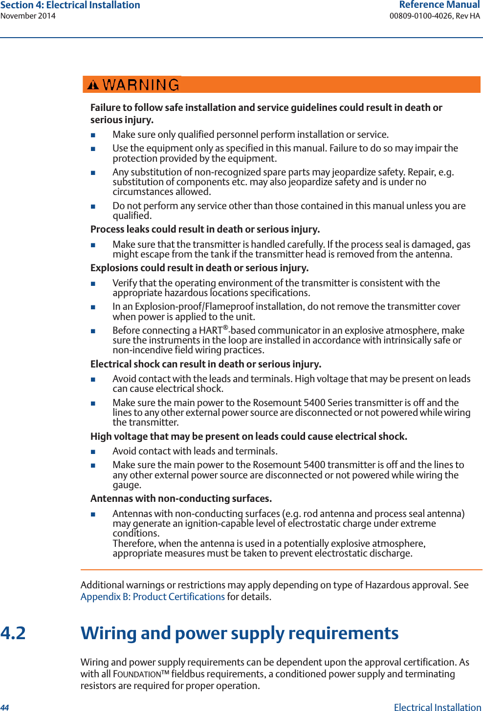
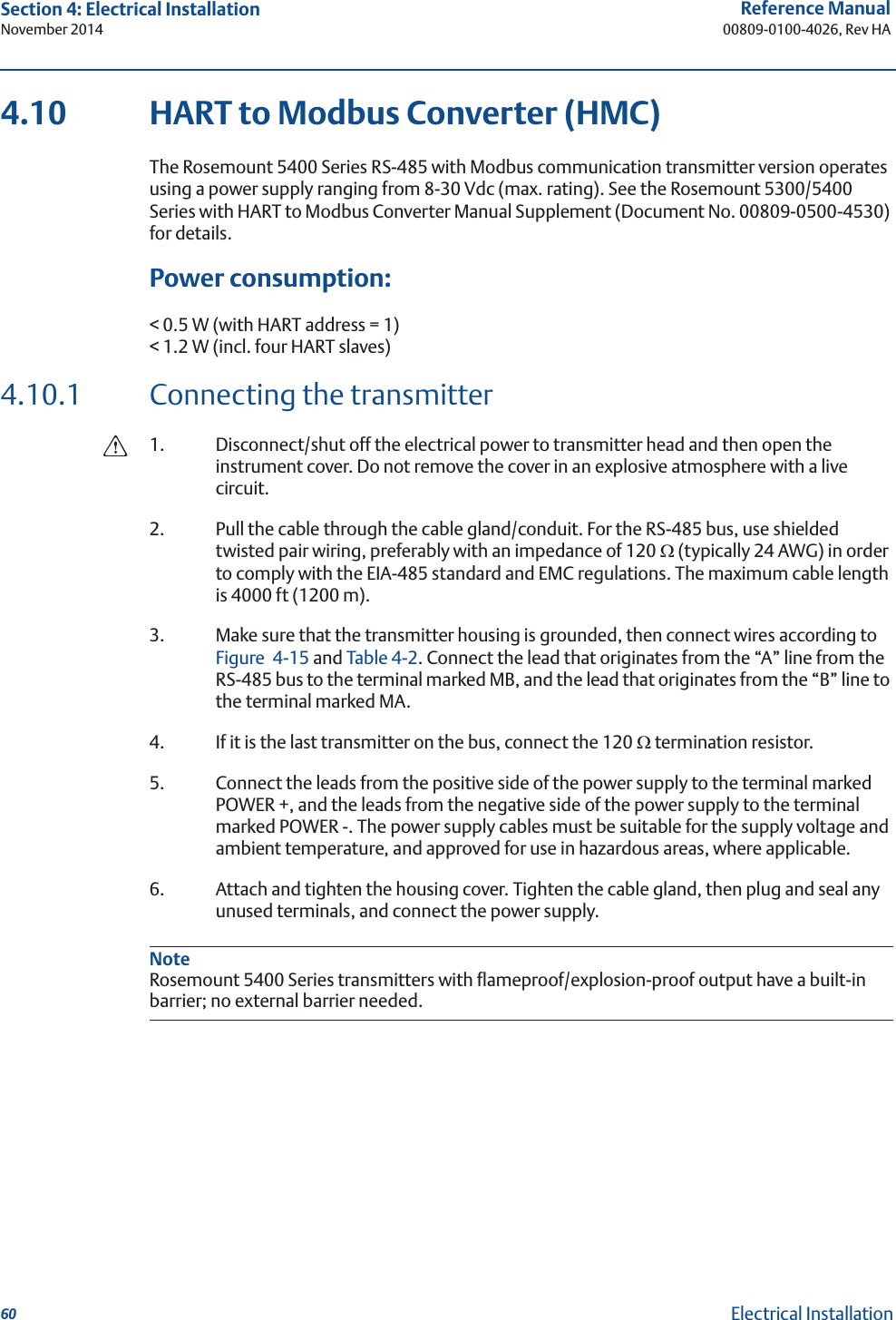
![120Reference Manual00809-0100-4026, Rev HASection 6: OperationNovember 2014Operation6.2 Viewing measurement data6.2.1 Using the display panelThe Rosemount 5400 Series transmitter uses an optional display panel to present measurement data. When the transmitter is switched on, the display panel presents information, such as transmitter model, measurement frequency, software version, communication type (HART, FF), serial number, HART identification tag, setting of write protection switch, and Analog Output settings.When the transmitter is operating, the display panel presents level, signal amplitude, volume, and other measurement data, depending on the display panel configuration (see “Specifying display panel variables” on page 120).The display has two rows, with the upper row showing the measured value and the bottom row showing the parameter name and measurement unit. The display toggles between the different variables every 2 seconds. Variables can be selected to be presented by using a Field Communicator, the AMS Suite, DeltaV, or the RRM software.Figure 6-1. The Rosemount 5400 Series Display PanelError messages are listed in sections “LCD display error messages” on page 126 and “LED error messages” on page 127.6.2.2 Specifying display panel variablesIt is possible to specify the variables to be presented on the display panel (LCD display).Using a Field CommunicatorFor a Field Communicator, the LCD display settings are available with HART command [2, 2, 3].FOUNDATION fieldbus parameters:TRANSDUCER_1100 > LCD_PARAMETERS.Toggling between measurement parameter and measurement unitMeasurement value](https://usermanual.wiki/Rosemount-Tank-Radar/05402/User-Guide-2448693-Page-132.png)

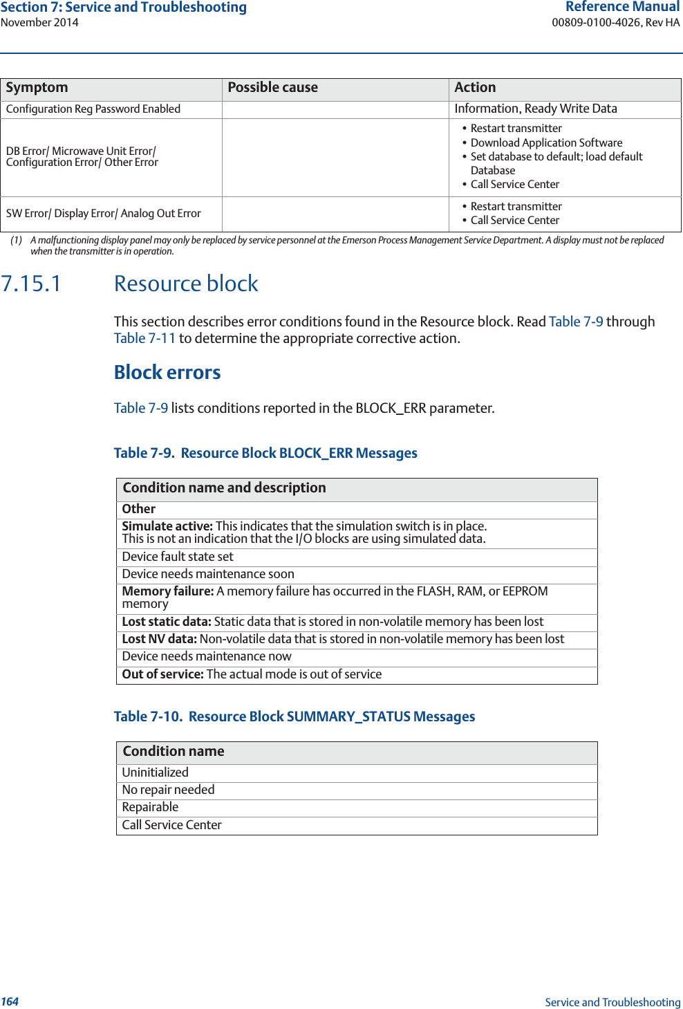
![140Reference Manual00809-0100-4026, Rev HASection 7: Service and TroubleshootingNovember 2014Service and Troubleshooting7.3.5 Using the Echo Curve Analyzer with a Field CommunicatorThe Field Communicator supports the EDDL with enhancements that allows viewing of the Echo Curve, creating an ATC, and specifying amplitude thresholds, such as the Surface Threshold.Viewing the Echo CurveTo view the Echo Curve:1. Select HART command [2, 5, 2, 3].FOUNDATION fieldbus parameter:TRANSDUCER_1300 > AMPLITUDE_THRESHOLD_CURVEThe Echo Curve appears on the display:2. Use the Hand and Zoom tools to view specific parts of the Echo Curve. The drop down list allows for choosing items, such as the different amplitude thresholds to be displayed in the plot.The Echo Curve plot also shows an ATC if available. See “ATC” on page 84 for more information.](https://usermanual.wiki/Rosemount-Tank-Radar/05402/User-Guide-2448693-Page-152.png)
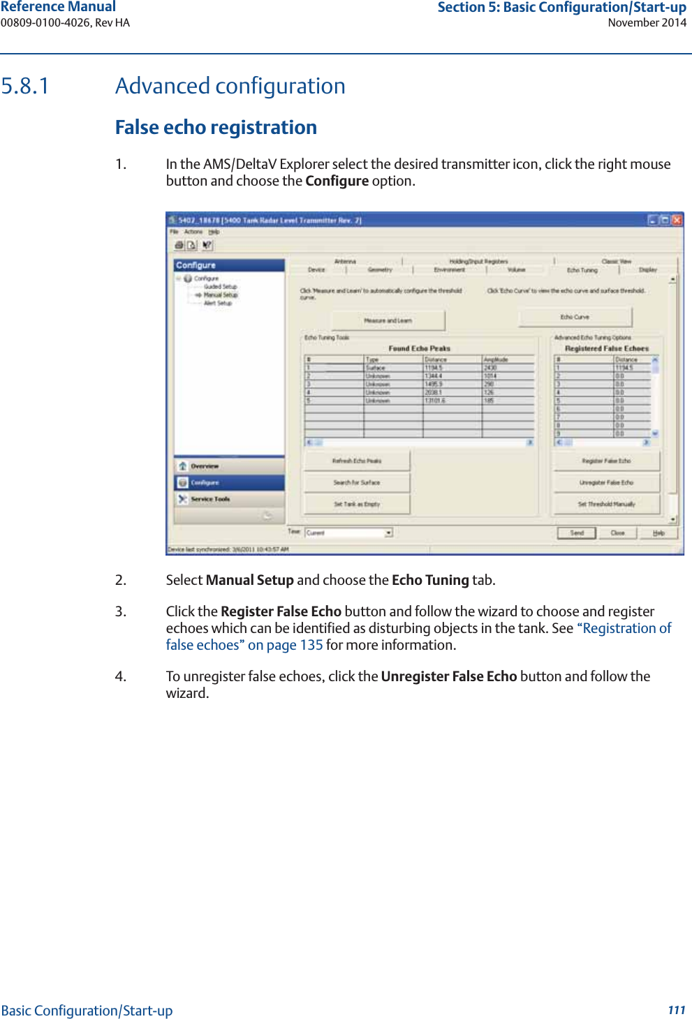
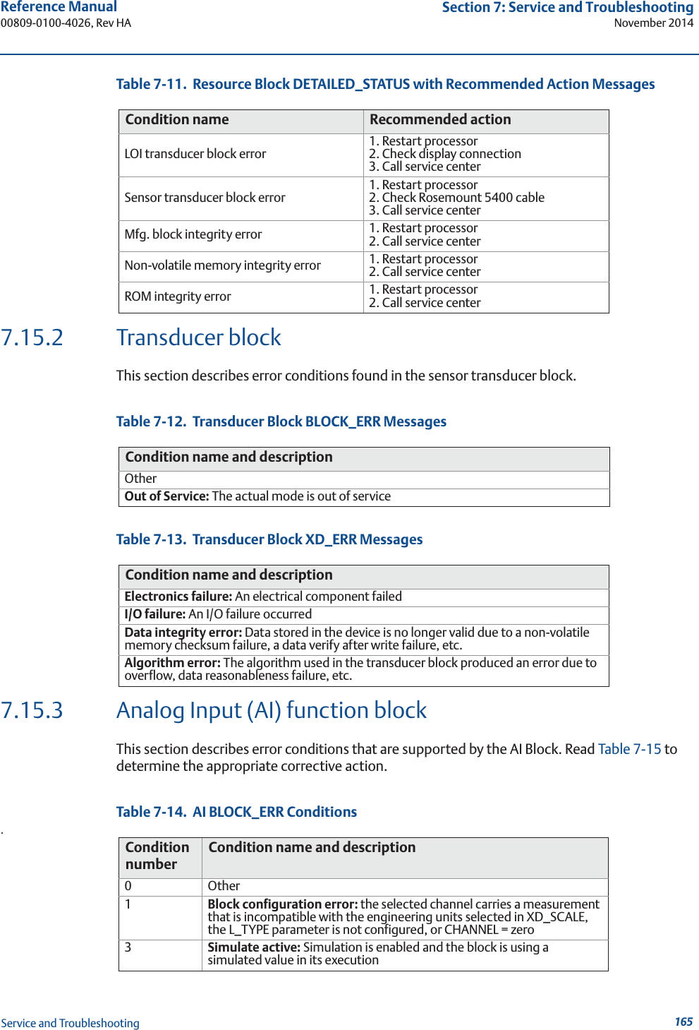
![141Reference Manual 00809-0100-4026, Rev HASection 7: Service and TroubleshootingNovember 2014Service and TroubleshootingRegister false echoesTo register false echoes:1. Select HART command [2, 5, 1].2. Select option 1 Found Echo Peaks to display found echoes.3. Select option 2 Add False Echo... to register false echoes based on distance.Threshold settingsTo adjust the amplitude thresholds:1. Select HART command [2, 5, 2].The different echo curve options appear on the display:2. Select option 1 Measure and Learn to create an ATC, see “ATC” on page 84 for more information.Select option 2 Set Threshold to specify a constant Surface Threshold.3. Click the SAVE button to store the new settings in the transmitter database.1 Found Echo Peaks2 Measurement Output3 Registered False Echoes4 Add False Echo...5 Remove False Echo...Peaks](https://usermanual.wiki/Rosemount-Tank-Radar/05402/User-Guide-2448693-Page-153.png)
![142Reference Manual00809-0100-4026, Rev HASection 7: Service and TroubleshootingNovember 2014Service and Troubleshooting7.4 Analog Output calibrationThis function calibrates the Analog Output by comparing the actual output current with the nominal 4 mA and 20 mA currents. Calibration is done at the factory and normally the transmitter does not need to be recalibrated.The Analog Output calibration function is available via theHART command [2, 7, 1].In RRM, this function is available via Setup > Output.To calibrate the Analog Output current:1. Start RRM and make sure that the transmitter communicates with the PC.2. Select the Output icon in the Device Config/Setup toolbar.3. Select the Analog Out tab in the Output window.4. Select the Calibrate DAC button.5. Follow the instructions to calibrate the 4 mA and the 20 mA outputs.](https://usermanual.wiki/Rosemount-Tank-Radar/05402/User-Guide-2448693-Page-154.png)
![149Reference Manual 00809-0100-4026, Rev HASection 7: Service and TroubleshootingNovember 2014Service and Troubleshooting7.10 Reset to factory settingsThis function resets all, or a specific part, of the holding registers to the factory settings. It is recommended that a backup of the configuration be made before resetting, so the old transmitter configuration can be loaded, if necessary.RRM: choose menu option Tools > Factory Settings.AMS Suite: Tools / Service > Factory Settings.HART Command: [1, 2, 8].AMS and DeltaV1. In the AMS/DeltaV explorer, select Configure/Service Tools, and choose Reset to Factory Settings.2. Choose the Factory Settings option.Reset to Factory Settings](https://usermanual.wiki/Rosemount-Tank-Radar/05402/User-Guide-2448693-Page-161.png)
![151Reference Manual 00809-0100-4026, Rev HASection 7: Service and TroubleshootingNovember 2014Service and Troubleshooting7.12 Using the Simulation ModeThis function can be used to simulate measurements and alarms. RRM: choose menu option Tools > Simulation Mode:AMS Suite: Tools > Service > Simulation Mode.HART Command: [3, 2, 1, 3].AMS and DeltaV1. In the AMS/DeltaV explorer select Configure/Service Tools, choose Simulate to setup simulation mode:Simulate](https://usermanual.wiki/Rosemount-Tank-Radar/05402/User-Guide-2448693-Page-163.png)
![152Reference Manual00809-0100-4026, Rev HASection 7: Service and TroubleshootingNovember 2014Service and Troubleshooting7.13 Write protecting a transmitterA Rosemount 5400 Series transmitter can be password protected from unintentional configuration changes. The default password is 12345 and it is recommended that this password not be changed to facilitate service and maintenance of the transmitter.RRM: Tools > Lock / Unlock Configuration Area.AMS Suite: Tools > Service > Lock / Unlock Device.HART Command [3, 2, 1, 2].AMS and DeltaV1. In the AMS/DeltaV explorer select Configure/Manual setup, choose the Device tab and select Lock/Unlock Device.2. Choose the Unlock/Lock Device option.Lock/Unlock Device](https://usermanual.wiki/Rosemount-Tank-Radar/05402/User-Guide-2448693-Page-164.png)

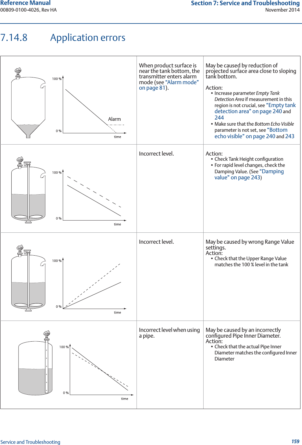
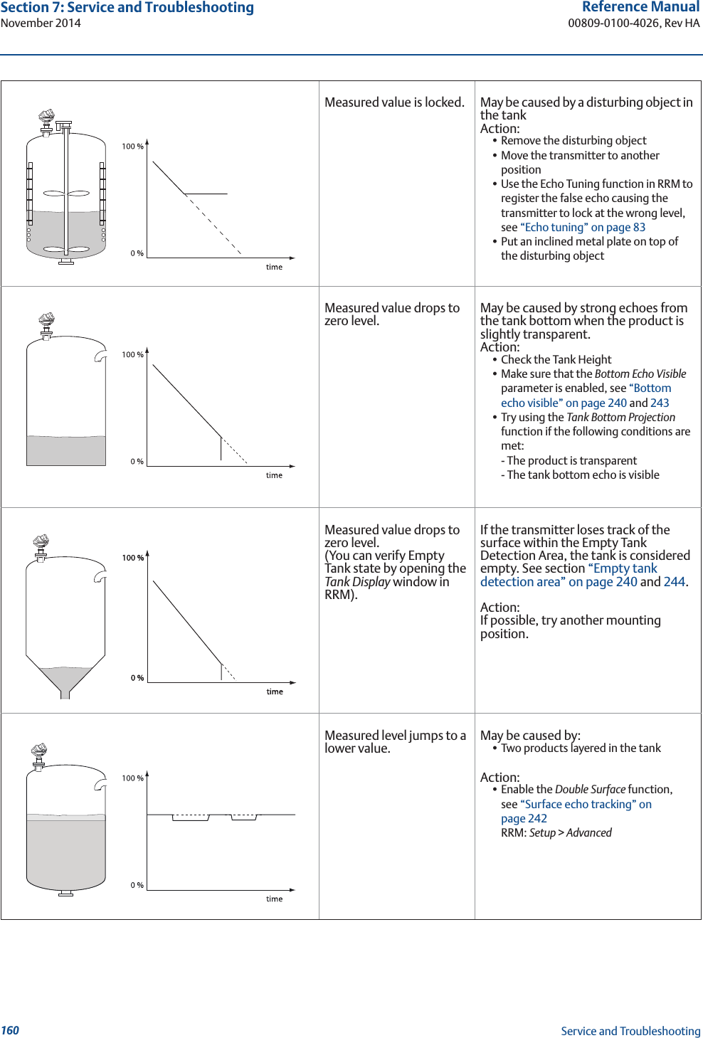
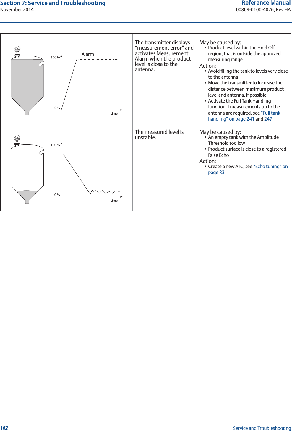
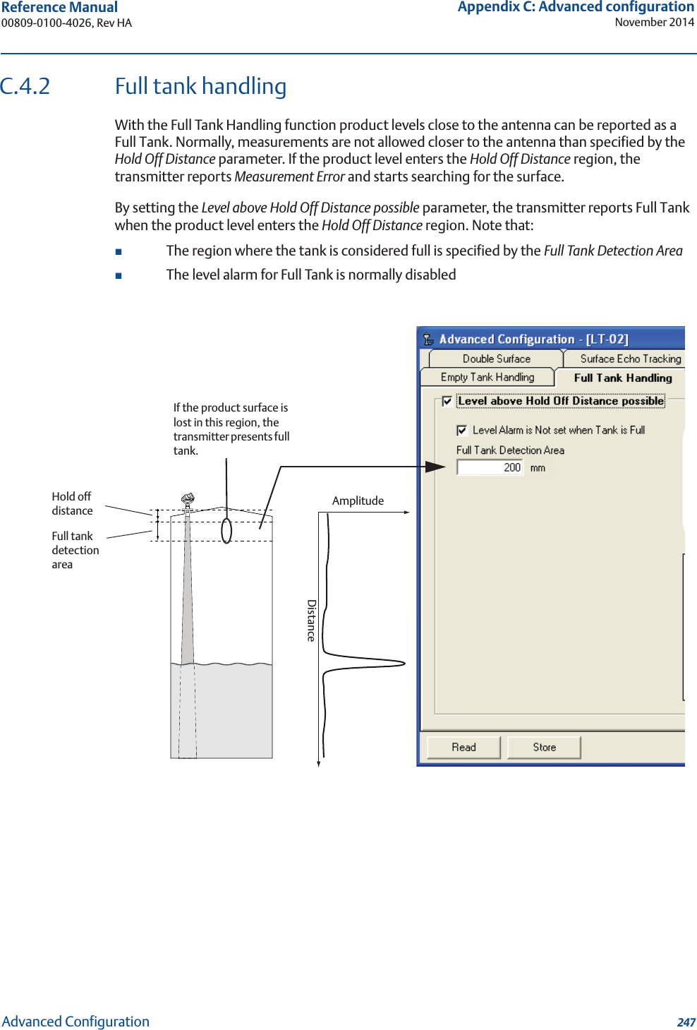
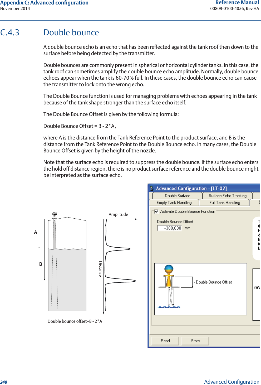
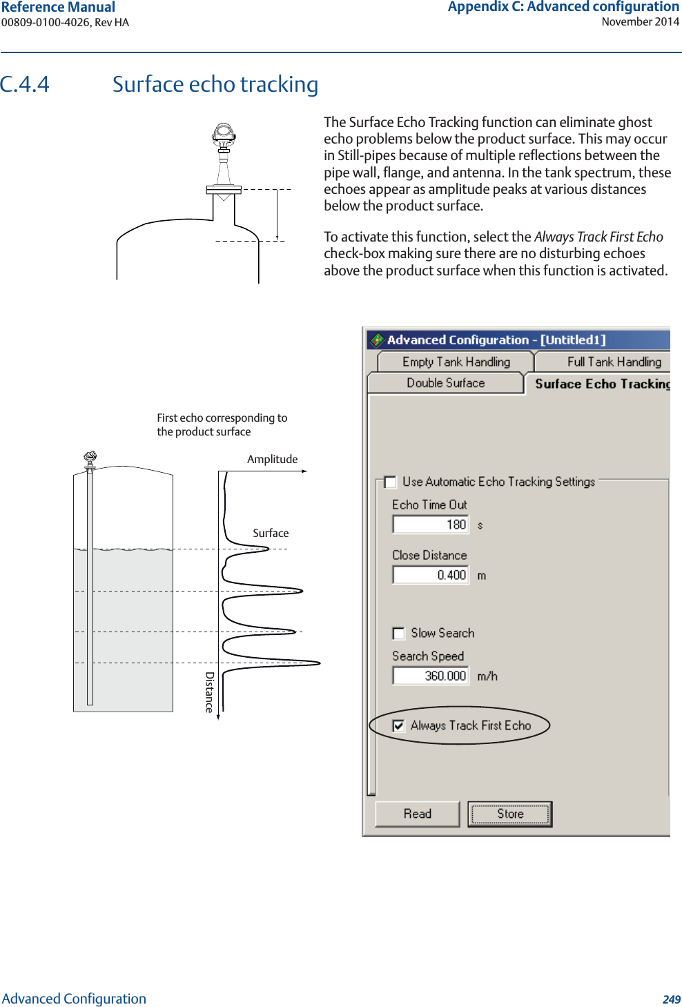
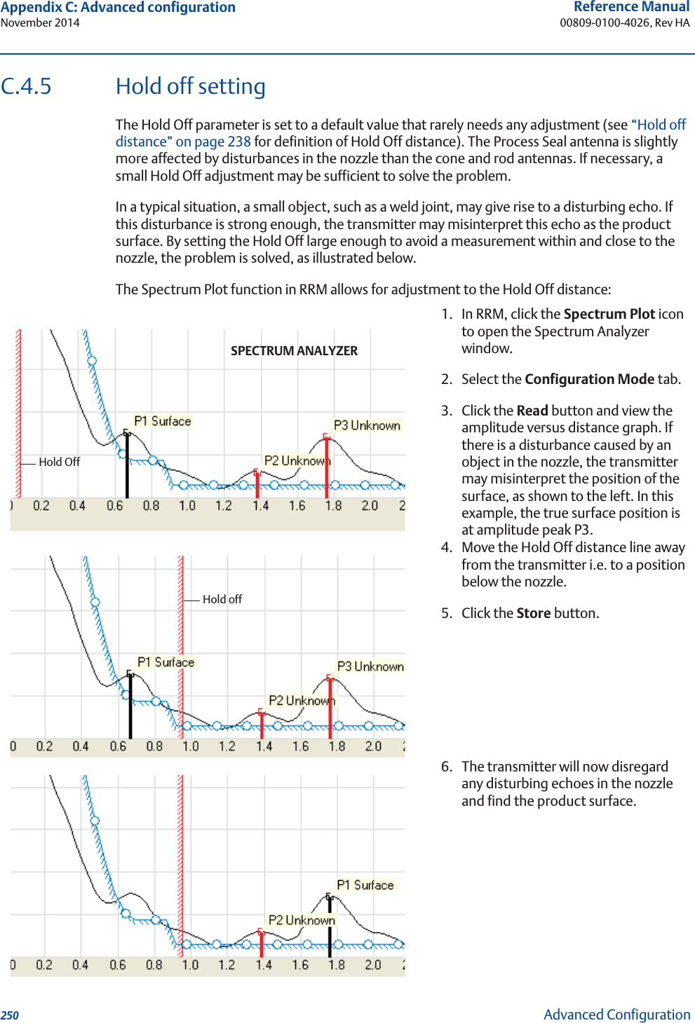
![161Reference Manual 00809-0100-4026, Rev HASection 7: Service and TroubleshootingNovember 2014Service and TroubleshootingIncorrect measurement level when the product surface is above the 50 % level.May be caused by:• Radar echo bouncing from the product surface to the tank roof then back to the surface• Strong echoes from a very high reflectivity productAction:• Move the transmitter from the center of the tank roof• Enable the Double Bounce function, see “Double bounce” on page 241 and 248RRM: Setup > AdvancedMeasured level jumps to a higher value. May be caused by:• Foam on the product surface• Turbulent product surfaceAction:• Enable the Tank Environment Foam parameterRRM: Setup > Tank > EnvironmentHART: [2, 3, 2]• Enable the Tank Environment Turbulent Surface parameterRRM: Setup > Tank > EnvironmentHART: [2, 3, 2]Measured level gets locked near the top of the tank.May be caused by:• Antenna tip ends inside the tank nozzle• Disturbing objects near the antenna• Product built up on the antennaAction:• Mount the transmitter on another nozzle, if possible• Increase the Hold Off distanceRRM: Setup > AdvancedHART: [2, 3, 4]The level value drops to a lower value when the product surface is close to the antenna.May be caused by:• Product level within the Hold Off region, that is outside the approved measuring range, and the transmitter is picking up secondary signal reflectionsAction:• Avoid filling the tank to levels close to the antenna• Move the transmitter to increase the distance between maximum product level and antenna, if possible• Activate the Full Tank Handling function if measurements up to the antenna are required, see “Full tank handling” on page 241 and 247](https://usermanual.wiki/Rosemount-Tank-Radar/05402/User-Guide-2448693-Page-173.png)


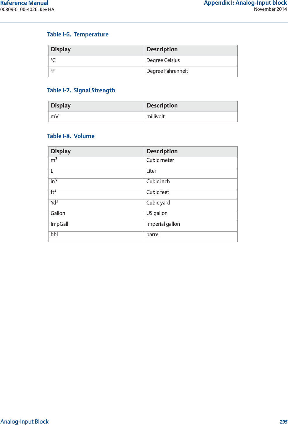
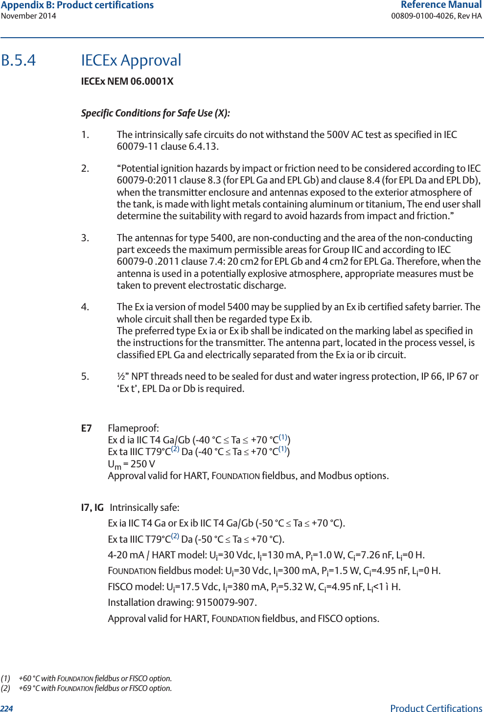
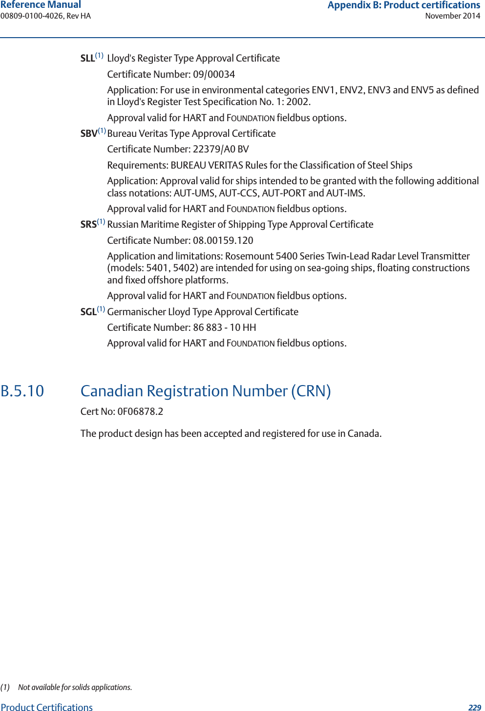
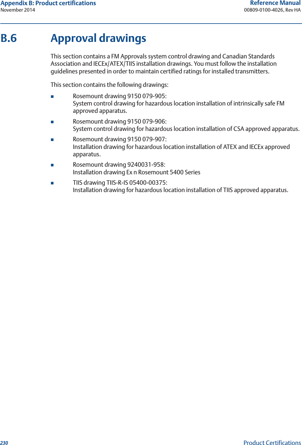
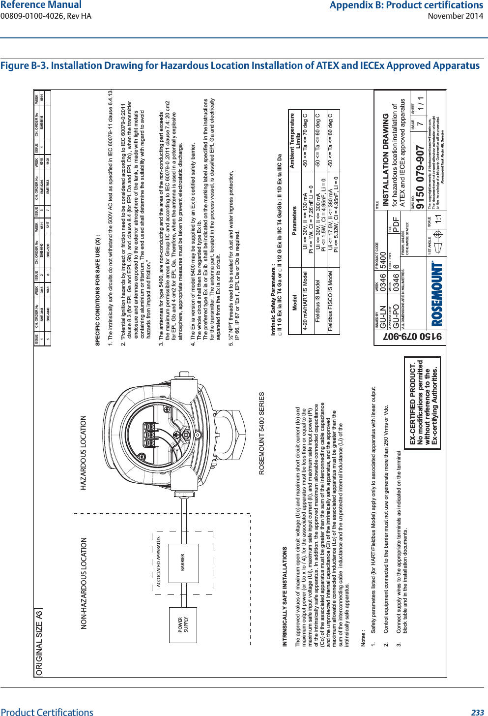
![221Reference Manual 00809-0100-4026, Rev HAAppendix B: Product certificationsNovember 2014Product CertificationsB.5.2 Canadian Standards Association (CSA) ApprovalsWhen bearing the “Dual Seal” marking, this product meets the Dual Seal Requirements of ANSI/ISA 12.27.01-2003.Cert. No.: 1514653E6 Explosion-proof with internal Intrinsically safe circuits [Exia] Class I, Div. 1, Groups B, C, and D;Temp. Code T4.Class II, Div. 1 and 2, Groups E, F, and G;Class III, Div. 1Ambient temperature limits -50 °C to +70 °C(1).Approval valid for HART, FOUNDATION fieldbus, and Modbus options.I6, IF Intrinsically safe Exia. Class I, Div. 1, Groups A, B, C, and D.Temp. Code T4.4-20 mA/HART model: Ui = 30 Vdc, Ii = 130 mA, Pi = 1.0 W, Ci = 7.26 nF, Li = 0 H.FOUNDATION fieldbus model: Ui = 30 Vdc, Ii = 300 mA, Pi = 1.3 W, Ci = 0 nF, Li = 0 H.FISCO model: Ui = 17.5 Vdc, Ii = 380 mA, Pi = 5.32 W, Ci = Li = 0.Installation drawing: 9150079-906.Ambient temperature limits: -50 °C to +70 °C(1).Approval valid for HART, FOUNDATION fieldbus, and FISCO options.(1) +60 °C with FOUNDATION fieldbus or FISCO option.](https://usermanual.wiki/Rosemount-Tank-Radar/05402/User-Guide-2448693-Page-233.png)
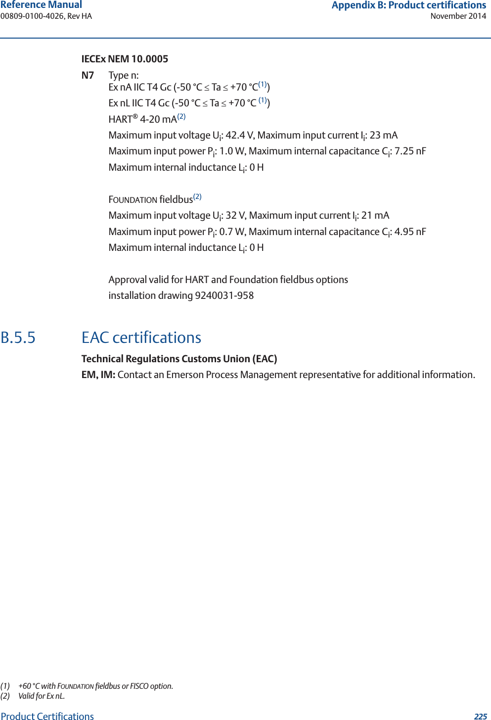
![227Reference Manual 00809-0100-4026, Rev HAAppendix B: Product certificationsNovember 2014Product CertificationsB.5.8 Japanese certificationsTechnology Institution of Industrial Safety (TIIS) ApprovalSpecial Condition for Safe Use (X):Refer to certificate TC20109-TC20111 (4-20 mA HART) and TC20244-TC20246 FOUNDATION fieldbus)E4(1) Flameproof: 4-20 mA HART model:Transmitter: Ex d [ia] IIC T4x-20 ~ +60 °CDC 20 - 42.4 VUm = 250 VUo = 22.2 VIo = 177 mAPo = 0.985 WAntennas: Ex ia IIC T4XFOUNDATION fieldbus model:Transmitter: Ex d [ia] IIC T4x-20 ~ +60 °CDC 16 - 32 VUm = 250 VUo = 22.2 VIo = 177.5 mAPo = 0.985 WAntennas: Ex ia IIC T4XInstallation drawing: 05400-00375.Approval valid for HART and FOUNDATION fieldbus options.(1) Not available for solids applications.](https://usermanual.wiki/Rosemount-Tank-Radar/05402/User-Guide-2448693-Page-239.png)
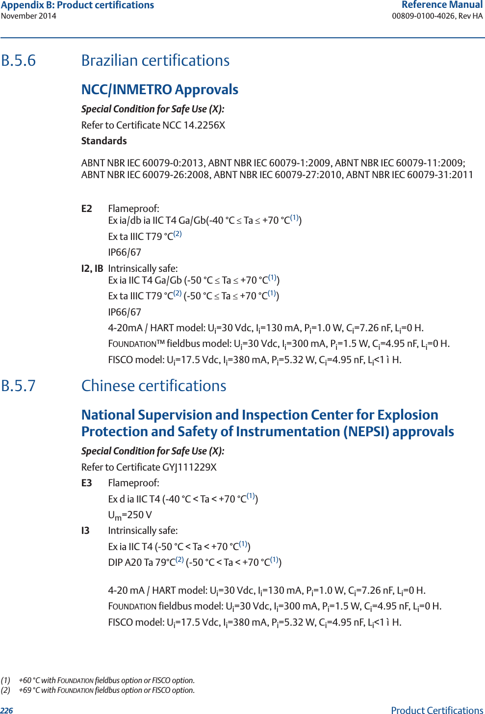
![235Reference Manual 00809-0100-4026, Rev HAAppendix B: Product certificationsNovember 2014Product CertificationsFigure B-5. Installation Drawing for Hazardous Location Installation of TIIS Approved Apparatus ᅜෆ(TIIS)㜵⇿ᵝ 1) ᑐ㇟ᶵჾ 㸺5401/5402㸼 㜵⇿グྕ ධຊ㒊 Ex d [ia] IIC T4 X, ಙྕኚ㒊ཬࡧࣥࢸࢼ Ex ia IIC T4 X ᐃ ᱁ ᮏᏳᅇ㊰ Uo = 22.2V Io = 177mA Po = 0.985W 㠀ᮏᏳᅇ㊰ 㟁※ DC 20~42.4V/4-20mA, DC 16~32V/ Fieldbus チᐜ㟁ᅽ AC 250V 50/60Hz, DC250V ࿘ᅖ ᗘ -20Υ㹼60Υ 1) ὀ㸸ᨵ㐀⚗Ṇࠋ 05400-00375B 㟼㟁Ẽ㜵Ṇࡢࡓࡵࣥࢸࢼ㒊ࡢᣔࡁ⚗Ṇࠋ Ⓨⅆ㜵Ṇࡢࡓࡵ㔠ᒓ㒊ࡢ⾪ᧁࡲࡓࡣᦶ᧿⚗Ṇࠋ ᥋ᆅ➃Ꮚࡣ㠀༴㝤ሙᡤ࠾࠸࡚ࠊ༢⊂࡛ A✀᥋ᆅᕤ‽ࡌ࡚᥋ᆅࡍࡿࡇࠋ ⇿Ⓨᛶ࢞ࢫࡲࡓࡣẼࡀᏑᅾࡍࡿሙᡤ࡛ࡣ࢝ࣂ࣮㛤ᨺ⚗Ṇࠋ እ㒊ᑟ⥺ࡣ⪏⇕ ᗘ 70Υ௨ୖࡢࢣ࣮ࣈࣝࢆ⏝ࡍࡿࡇࠋ 2) ୍⯡ᅇ㊰(㟁※ཬࡧධฟຊ)ࡣࡑࡢධຊ㟁※,ᶵჾෆ㒊ࡢ㟁ᅽ➼ࡀṇᖖ≧ែ࠾ࡼࡧ␗ᖖ≧ែ࠾࠸࡚ࡶ AC/DC250V 50/60Hz ࢆ㉸࠼࡞࠸ࡶࡢࡍࡿࠋ ᮏᏳ⏝᥋ᆅ➃Ꮚࡣ㠀༴㝤ሙᡤ࠾࠸࡚༢⊂࡛ $ ✀᥋ᆅࡍࡿࠋ ࢩࢫࢸ࣒ᵓᡂᅗ 2)](https://usermanual.wiki/Rosemount-Tank-Radar/05402/User-Guide-2448693-Page-247.png)

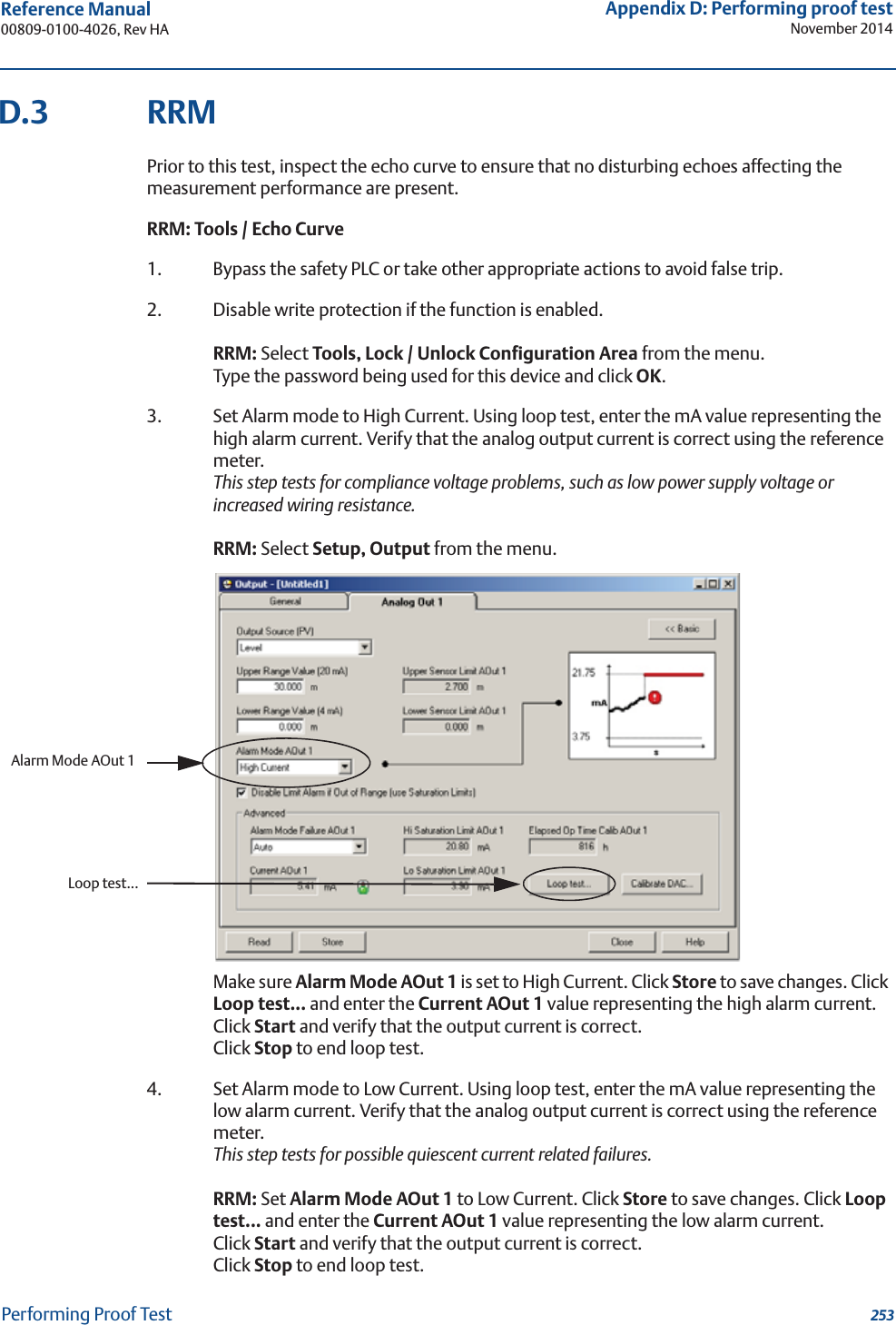
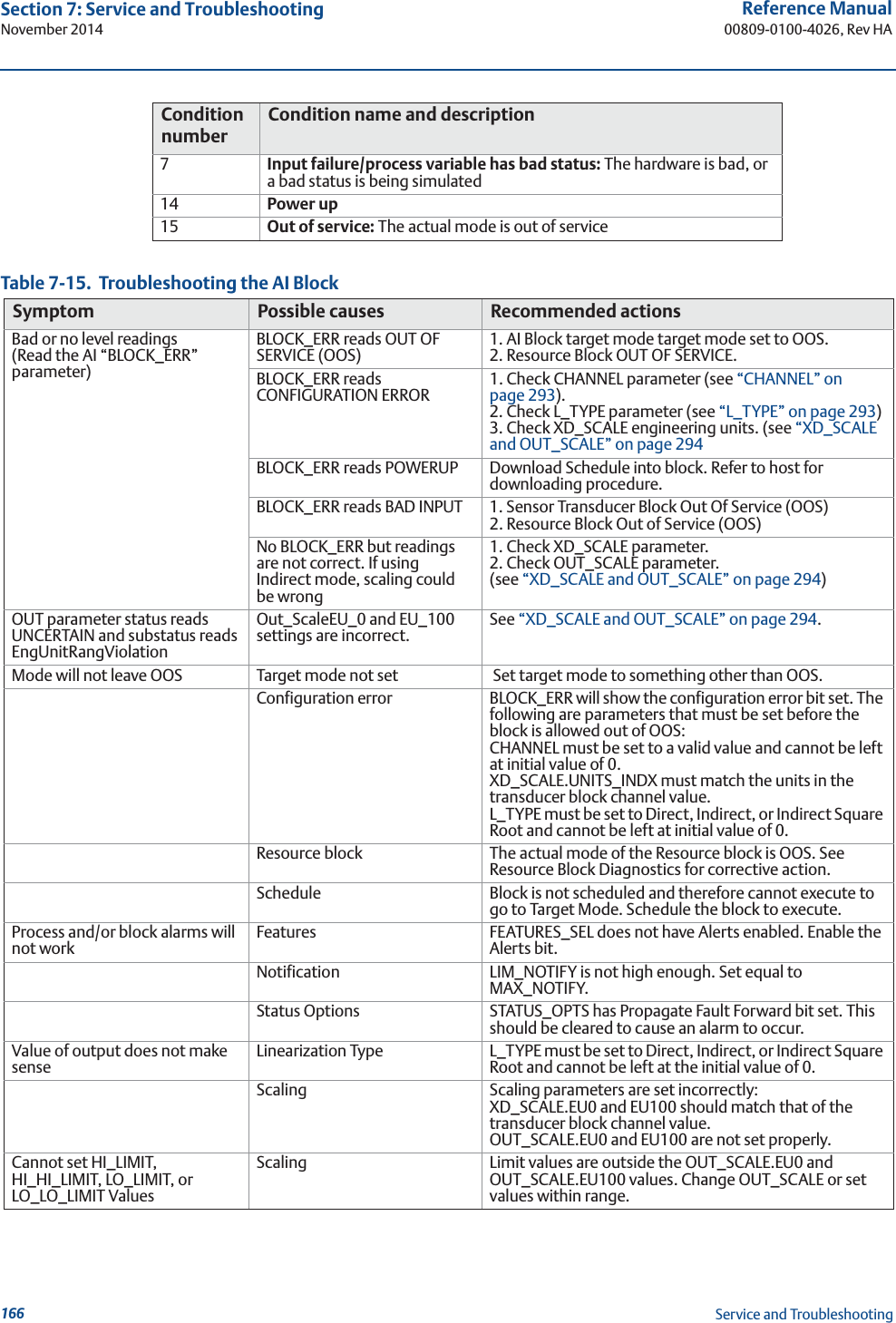
![251Reference Manual 00809-0100-4026, Rev HAAppendix D: Performing proof testNovember 2014Performing Proof TestAppendix D Performing Proof TestPerforming proof test . . . . . . . . . . . . . . . . . . . . . . . . . . . . . . . . . . . . . . . . . . . . . . . . . . . . . . . . page 251Field communicator . . . . . . . . . . . . . . . . . . . . . . . . . . . . . . . . . . . . . . . . . . . . . . . . . . . . . . . . . page 251RRM . . . . . . . . . . . . . . . . . . . . . . . . . . . . . . . . . . . . . . . . . . . . . . . . . . . . . . . . . . . . . . . . . . . . . . . page 253AMS Suite . . . . . . . . . . . . . . . . . . . . . . . . . . . . . . . . . . . . . . . . . . . . . . . . . . . . . . . . . . . . . . . . . . page 255D.1 Performing proof testThis test detects approximately 95 % of the possible Dangerously Undetected (DU) failures of the transmitter including the sensor element. Here is a description of how to perform the test using a Field Communicator, RRM, or AMS® Suite. Note that the transmitter is not safety-rated during proof tests. Alternative means should be used to ensure process safety during such activities.Required tools: HART® host/communicator and a mA meter.D.2 Field communicatorPrior to this test, inspect the echo curve to ensure that no disturbing echoes affecting the measurement performance are present.HART Sequence: [2, 6, 1]1. Bypass the safety PLC or take other appropriate actions to avoid false trip.2. Disable write protection if the function is enabled.HART Sequence: [3, 2, 1, 2, 1]. Type the password.3. Using loop test, enter the mA value representing the high alarm current. Verify that the analog output current is correct using the reference meter.This step tests for compliance voltage problems, such as low power supply voltage or increased wiring resistance.HART Sequence: [2, 4, 1, 7]. Select 3 Other. Enter the analog output level representing the high alarm current. Press Enter and click OK.Verify that the analog output current is correct. Click Abort to end loop test.4. Using loop test, enter the mA value representing the low alarm current. Verify that the analog output current is correct using the reference meter.This step tests for possible quiescent current related failures.HART Sequence: [2, 4, 1, 7]. Select 3 Other. Enter the analog output level representing the low alarm current. Press Enter and click OK.Verify that the analog output current is correct. Click Abort to end loop test. Verify that the Current output is restored to the original mode.](https://usermanual.wiki/Rosemount-Tank-Radar/05402/User-Guide-2448693-Page-263.png)
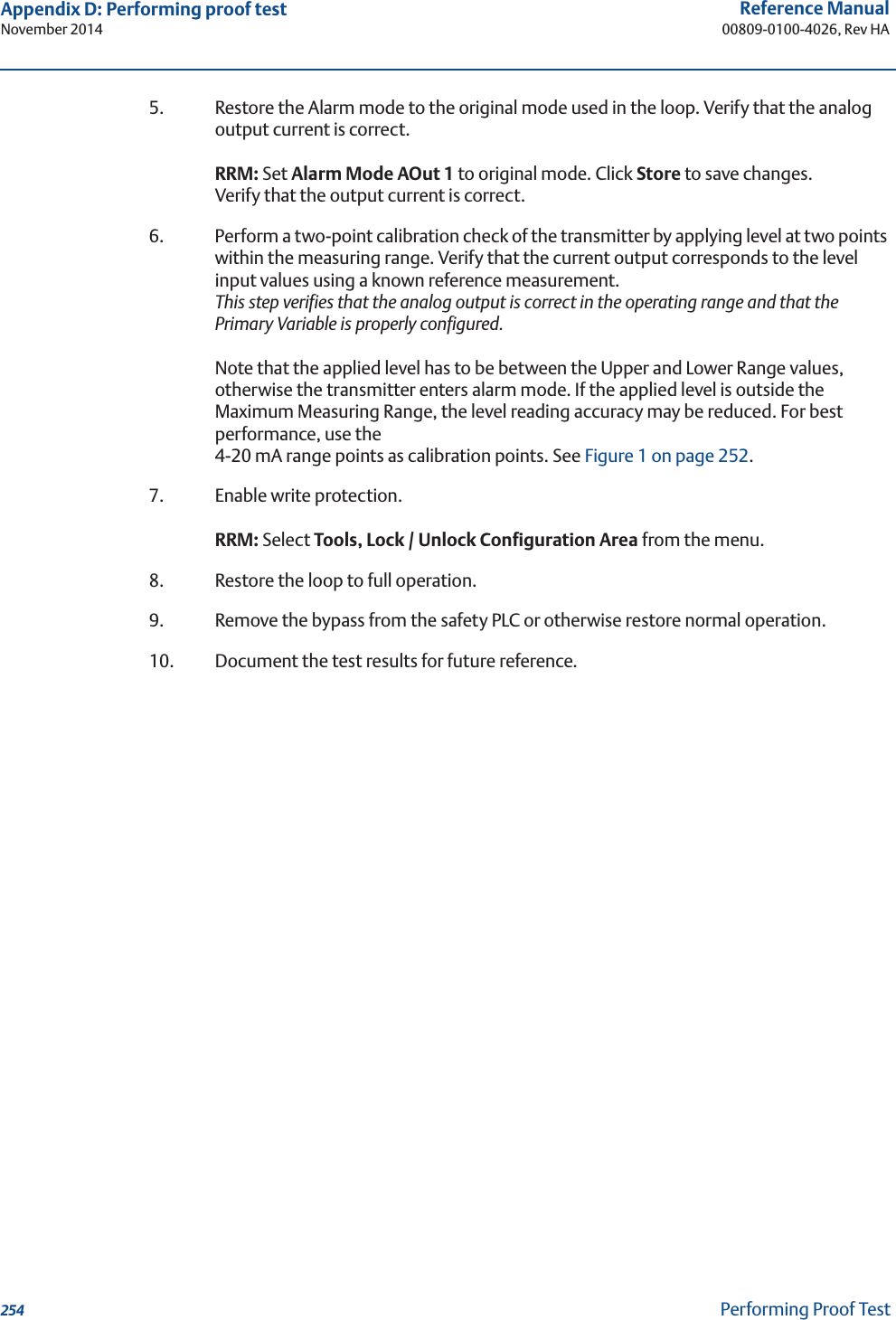
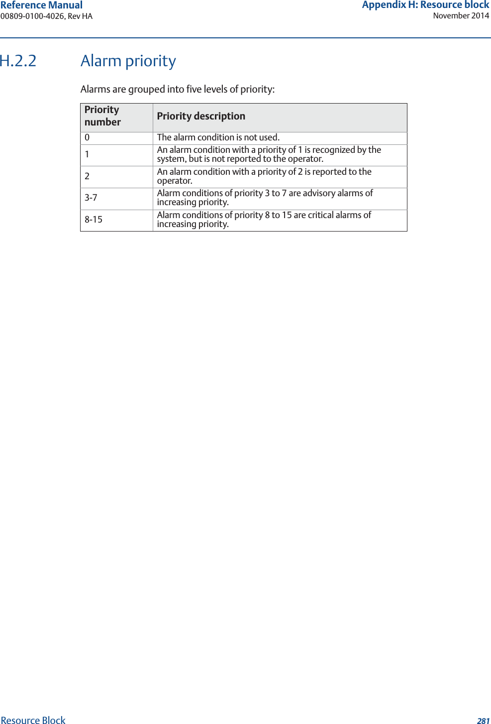
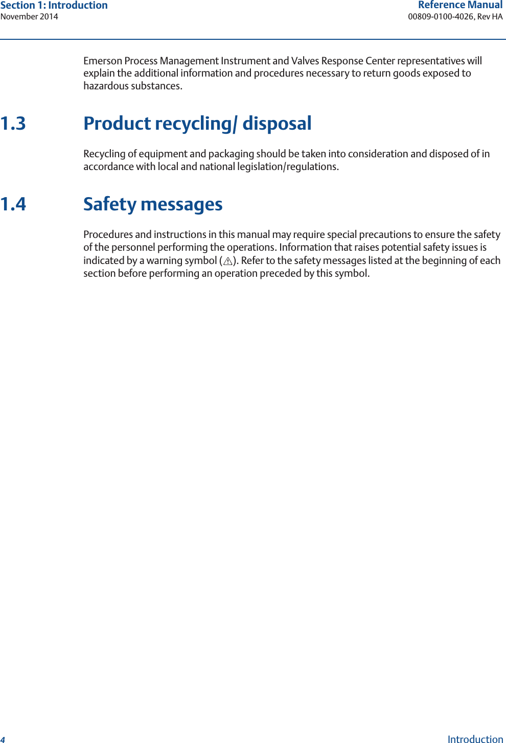
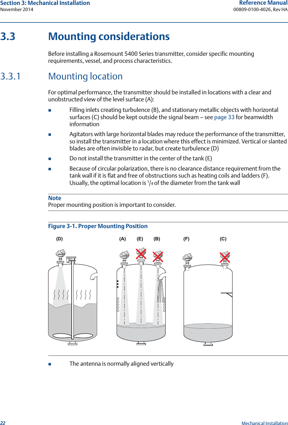
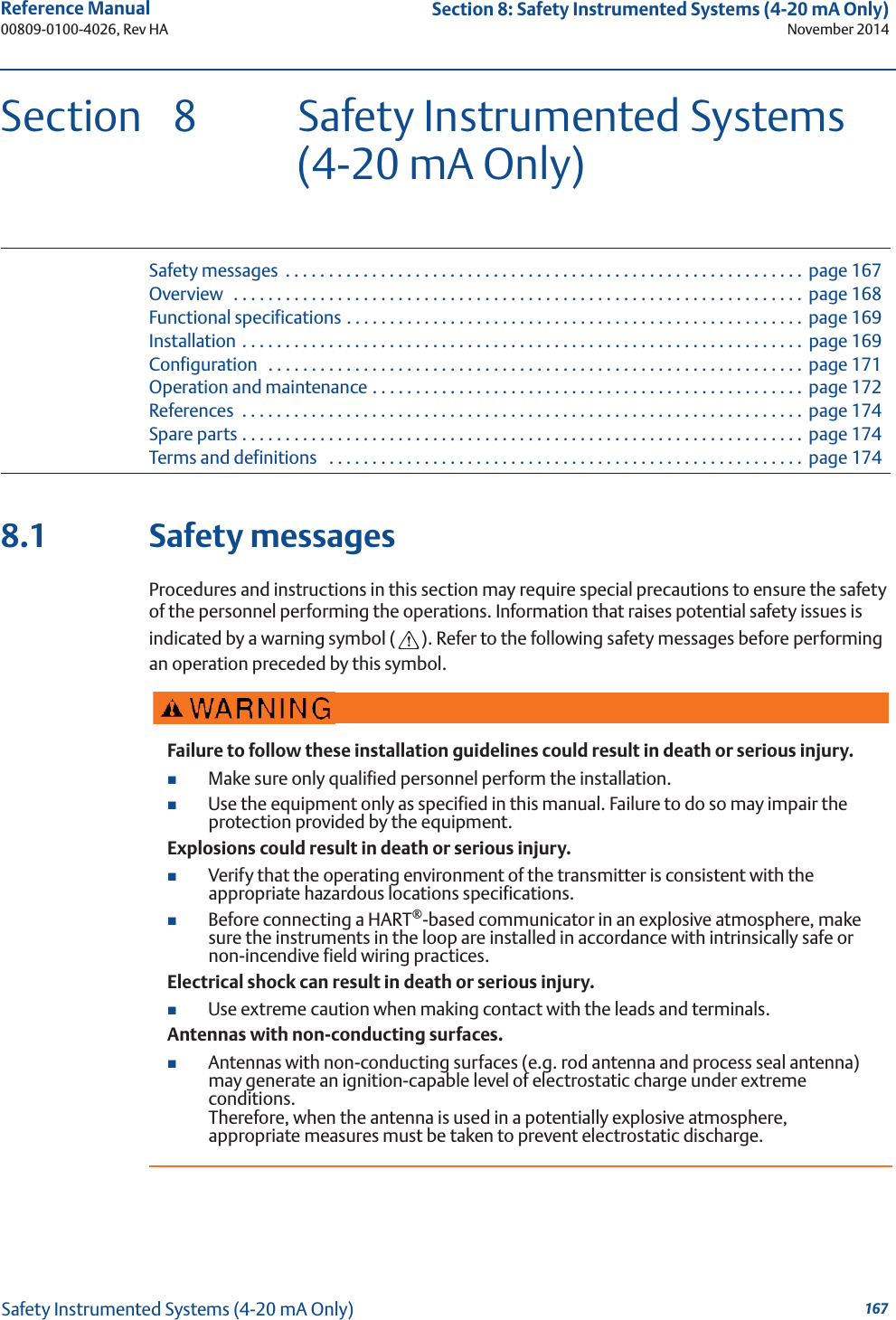
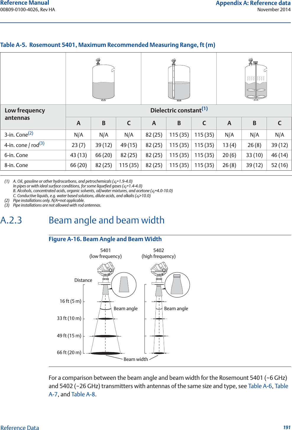
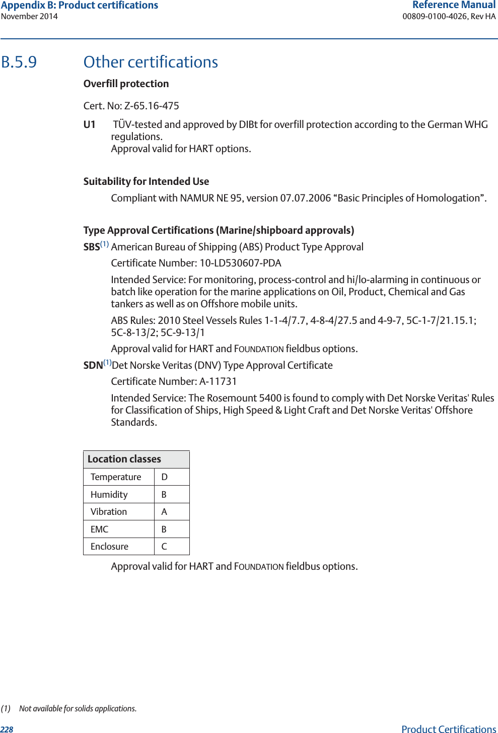
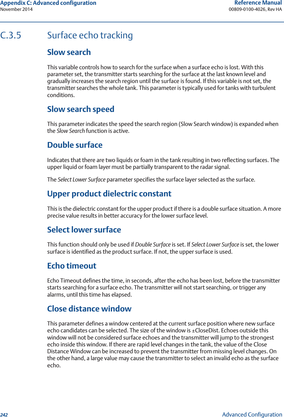
![252Reference Manual00809-0100-4026, Rev HAAppendix D: Performing proof testNovember 2014Performing Proof TestFigure D-1. Range Values5. Perform a two-point calibration check of the transmitter by applying level at two points within the measuring range. Verify that the current output corresponds to the level input values using a known reference measurement.This step verifies that the analog output is correct in the operating range and that the Primary Variable is properly configured.Note that the applied level has to be between the Upper and Lower Range values, otherwise the transmitter enters alarm mode. If the applied level is outside the Maximum Measuring Range, the level reading accuracy may be reduced. For best performance, use the 4-20 mA range points as calibration points. See Figure 1.6. Enable write protection.HART Sequence: [3, 2, 1, 2, 1].7. Restore the loop to full operation.8. Remove the bypass from the safety PLC or otherwise restore normal operation.9. Document the test results for future reference.20 mA Upper Range Value (URV)Product Level4 mA Lower Range Value (LRV)Range 0-100 %Upper Reference PointMin Level Offset (C)Hold Off DistanceLower Reference Point(Level=0)](https://usermanual.wiki/Rosemount-Tank-Radar/05402/User-Guide-2448693-Page-264.png)