Rosemount Tank Radar REXX Radar Level Gauge User Manual Installation manual
Rosemount Tank Radar AB Radar Level Gauge Installation manual
Installation manual
INSTALLATION
MANUAL
W11W12
FOR
INTRINSICALLY
SAFE CIRCUITS
ONLY
"i"
W11W12
FOR
INTRINSICALLY
SAFE CIRCUITS
ONLY
"i"
W11W12
FOR
INTRINSICALLY
SAFE CIRCUITS
ONLY
"i"
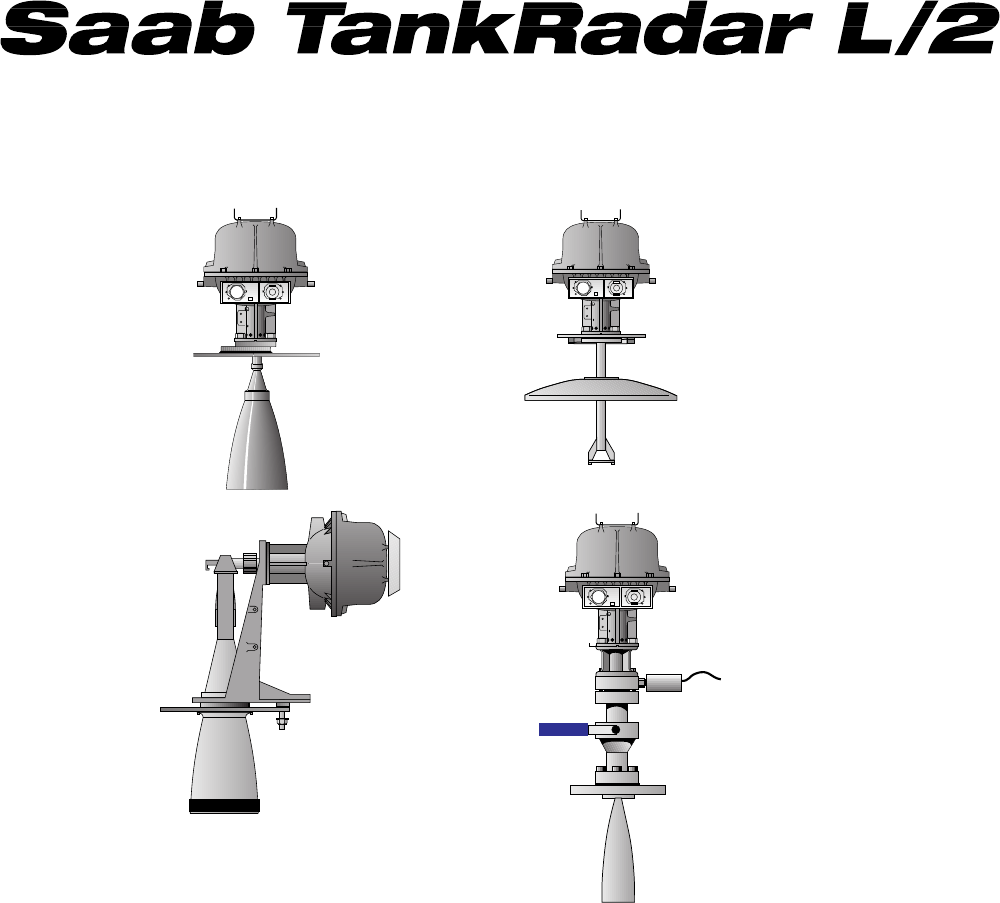
Parabolic
Antenna
Gauge
Still Pipe
Gauge
Horn
Antenna
Gauge
LPG/LNG
Gauge
Copyright © June 1995
Saab Marine Electronics AB
US Version

2
Saab TankRadar L/2
US Version. Seventh edition, June 1995
Installation Manual
Copyright © June 1994
Saab Marine Electronics AB
The contents, descriptions and specifications within this manual is
subject to change without notice. Saab Marine Electronics AB
accepts no responsibility for any errors that may appear in this
manual.
The manuals available for TankRadar L/2 are
- Technical Description
- Installation Manual
- Operator’s Manual
- Operator’s Manual for OPI/2
- COS Operator’s Manual
- Service Manual
The Technical Description contains all technical data on the vari-
ous parts of the TankRadar L/2 System.
The Installation Manual is used for planning and performing the
installation of the system.
Once the parts of the system have been installed, then use either
the Operator’s Interface (OPI) or the Configuration Software
(COS) to configure the system. See the OPI Operator’s Manual or
the COS Operator’s Manual for detailed explanation.
The OPI Operator’s Manual describes how to operate the
TankRadar L/2 System using the Operator’s Interface software on
a personal computer.
The Operator’s Manual for OPI/2 describes Operator’s Interface
with the optional inventory functions included, designated OPI/2.
The COS Operator’s Manual describes how to use the Configura-
tion Software (COS).

Saab TankRadar L/2
3
US Version. Seventh edition, June 1995
Installation Manual
Contents
The manuals available for TankRadar L/2 are ............................................... 2
Denominations and abbreviations used in this manual: .............................. 6
1 Introduction to the TankRadar L/2 System .................................... 7
2 Safety ............................................................................................... 10
2.1 Intrinsic Safety .................................................................................. 10
2.2 Explosion Proof................................................................................. 11
2.3 Specific FCC Requirements (US market only) ............................. 11
3 Description of the Radar Tank Gauges ......................................... 12
3.1 Transmitter Head............................................................................. 12
3.1.1 Electronic Unit ............................................................................ 13
3.1.2 Cable Outputs ............................................................................. 13
3.1.3 Power Supply to the Radar Tank Gauge................................. 14
3.1.4 Barrier Unit Card, BU (Option) ................................................ 14
3.1.5 Current Loop Card, CLC (Option)........................................... 15
3.1.6 Metrological Seal ........................................................................ 15
3.1.7 Installation Data for the Transmitter Head............................. 15
3.2 Description of the Horn Antenna Gauge, RTG 2920.................... 16
3.2.1 Installation Data for RTG 2920 ................................................. 16
3.3 Description of the Parabolic Antenna Gauge, RTG 2930............. 17
3.3.1 Installation Data for RTG 2930 ................................................. 17
3.4 Description of the Still Pipe Gauge, RTG 2940 ............................. 18
3.4.1 Installation Data for RTG 2940 ................................................. 18
3.5 Description of the LPG/LNG Gauge, RTG 2960 ........................... 19
3.5.1 Installation Data for RTG 2960 ................................................. 19
4 Description of the Data Acquisition Units ................................... 20
4.1 Connection of the Sensors .............................................................. 20
4.2 Selecting the Temperature Range .................................................. 21
4.3 Local Readout Display ..................................................................... 21
4.4 Write Enable/Inhibit Switch............................................................ 21
4.5 Common Installation Data for Both DAUs ................................... 22
4.6 Description of the Slave Data Acquisition Unit, DAU 2100......... 22
4.6.1 Installation Data for DAU 2100 ................................................ 22
4.7 Description of the Independent Data Acquisition Unit................ 23
4.7.1 Power Supply.............................................................................. 23
4.7.2 Relays (Optional)........................................................................ 23
4.7.3 Installation Data for DAU 2130 ................................................ 24
5 Description of the Field Bus Modem, FBM 2170 ......................... 24
5.1 Installation Data for FBM 2170 ................................................. 24
6 Description of the Field Communication Unit, FCU 2160......... 25
6.1 Communication Ports ..................................................................... 25
6.2 FCU Enclosure.................................................................................. 26
6.3 FCU Power Supply ........................................................................... 26
6.4 Write Inhibit/Enable Switch............................................................ 26
6.5 Installation Data for FCU 2160....................................................... 27

4
Saab TankRadar L/2
US Version. Seventh edition, June 1995
Installation Manual
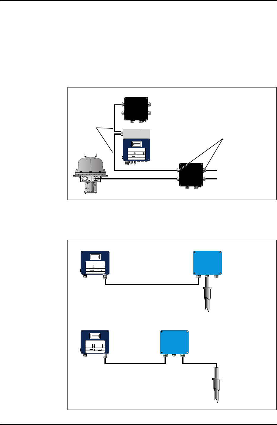
7 Description of the Junction Boxes................................................. 28
7.1 Junction Box JB 8 for Connection of RTG to Slave DAU ............. 28
7.2 Junction Box JB 12 for Connection of RTG (with CLC) to
Slave DAU ......................................................................................... 28
7.3 Junction Box JB 16 for Connection to RTG and Independent DAU
29
7.4 Junction Box JB 36 for Connection of Temperature Sensors ....... 29
8 Connection to a Plant Host Computer (Plant DCS) .................. 29
8.1 Connect to the FCU for Quick Updates........................................ 30
8.2 Connect to OPI/2 for Inventory Data ............................................ 30
9 Installation Schedule ...................................................................... 30
10 Requirements on the installation of the Radar Tank Gauges ..... 31
10.1 Requirements for the Horn Antenna Gauge, RTG 2920 .............. 32
10.1.1 Free Space Requirement ............................................................ 32
10.1.2 Socket Requirement.................................................................... 33
10.2 Requirements for Parabolic Antenna Gauge, RTG 2930.............. 34
10.2.1 Inclination of the Parabolic Antenna Gauge........................... 34
10.2.2 Free Space Requirement ............................................................ 35
10.2.3 Flange Requirements ................................................................. 36
10.2.4 New Tanks................................................................................... 36
10.2.5 Socket Requirements.................................................................. 37
10.3 Requirements for the Still Pipe Gauge, RTG 2940 ....................... 38
10.3.1 Still Pipe Requirements.............................................................. 38
10.3.2 Flange Requirements ................................................................. 38
10.3.3 New Tanks................................................................................... 39
10.3.3 Service Space ............................................................................... 39
10.4 Requirements for the LPG/LNG Gauge, RTG 2960 ..................... 40
10.4.1 Temperature and Pressure Measurement ............................... 40
10.4.2 Still Pipe ....................................................................................... 40
10.4.3 References in Still Pipe............................................................... 40
10.4.4 System with Reference Pin and Reflector Plug...................... 41
10.4.5 System with Reference Pins Only ............................................ 41
10.4.6 Extension Pipe for Minimum Distance ................................... 41
11 Mechanical Installation of the Radar Tank Gauges ...................... 42
11.1 Installation of Horn Antenna Gauge, RTG 2920 ........................... 42
11.2 Installation of the Parabolic Antenna Gauge, RTG 2930 ............. 44
11.3 Installation of the Still Pipe Gauge, RTG 2940.............................. 47
11.4 Installation of the LPG/LNG Gauge, RTG 2960 ............................ 50
12 Electrical Installation...................................................................... 53
12.1 Cabling for Power Supply ................................................................ 53
12.2 Cabling for TRL/2 Bus ...................................................................... 54
12.3 Grounding ......................................................................................... 54
12.4 Electrical Installation of the Radar Tank Gauge, RTG .................. 54
12.4.1 The Non-Intrinsically Safe Connection (W11)........................ 54
12.4.2 The Intrinsically Safe Connection (W12)................................. 54

Saab TankRadar L/2
5
US Version. Seventh edition, June 1995
Installation Manual
12.5 Electrical Installation of the Data Acquisition Unit, DAU ........... 55
12.5.1 Electrical Installation of the Slave DAU, DAU 2100.............. 55
12.5.2 Electrical Installation of the Independent DAU, 2130........... 55
12.6 Electrical Installation of the Field Bus Modem, FBM 2170 .......... 56
12.7 Electrical Installation of the Field Communication Unit,
FCU 2160 .......................................................................................... 56
13 List of Drawings .............................................................................. 57
13.1 Mechanical Installation .................................................................... 57
13.2 Electrical Installation ....................................................................... 57
14 Description of the Required System Information ....................... 58
14.1 System Configuration ...................................................................... 58
14.2 System Master .................................................................................. 58
14.3 Plant Host Computer System (Plant DCS) .................................. 58
14.1.3 Tank Data ..................................................................................... 58
Required System Information Form......................................... Appendix 1
Index.................................................................................................... Index 1

6
Saab TankRadar L/2
US Version. Seventh edition, June 1995
Installation Manual
Denominations and abbreviations used in this manual:
BU - Barrier Unit
CLC - Current Loop Card
DAU - Data Acquisition Unit
DMB - DAU Mother Board
DOS - Disk Operating System. An operating system
for PC’s.
DPS - DAU Power Supply board
DXB - DAU Extended Board
EEPROM - Electrically Erasable PROM
FBM - Field Bus Modem
FCC - Federal Communications Commission
FCU - Field Communication Unit
FMCW - Frequency Modulated Continuous Wave
FSK - Frequency Shift Keyed
IS - Intrinsically Safe
JB - Junction Box
LCD - Liquid Crystal Display
OPI - Operator’s Interface
OS/2 - An operating system for PC’s.
PC - Personal Computer
PCB - Printed Circuit Board
PROM - Programmable Read Only Memory
PTFE - Polytetrafluoroethylene. A polymer also mar-
keted as Teflon.
RF-head - A device for emitting and receiving micro-
waves.
RTD - Resistance Temperature Detectors
RTG - Radar Tank Gauge
TH - Transmitter Head
TRL - Tank Radar L (First generation)
TRL/2 - Tank Radar L/2
VAC - Volts Alternating Current
VDC - Volts Direct Current
Saab TankRadar L/2
7
US Version. Seventh edition, June 1995
Installation Manual
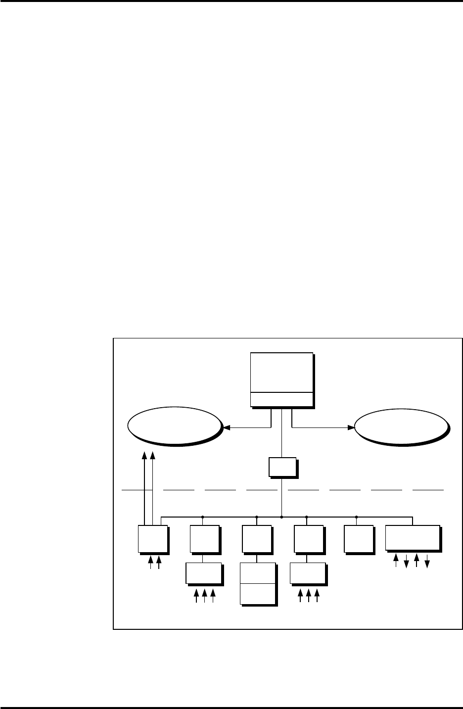
1 Introduction to the TankRadar L/2 System
The TankRadar L/2 System is a monitoring and control system for
tank level gauging. The system can interface various sensors, such
as temperature and pressure sensors, for complete inventory
control.
There is a distributed intelligence in the various units of the sys-
tem. The units continuously collect and process information.
When a request for information is received an immediate response
is sent with updated information. The units communicate with
each other on a field bus, the TRL/2 Bus.
No part of the equipment is in actual contact with the product in
the tank and the antenna is the only part of the gauge that is ex-
posed to the tank atmosphere. The Radar Tank Gauge sends mi-
crowaves towards the surface of the product in the tank. The level
is calculated based on the echo from the surface.
TankRadar L/2 can measure the level of almost any product,
including bitumen, crude oil, refined products, aggressive chemi-
cals, LPG and LNG, etc. Using a suitable Tank Connection Unit,
the TankRadar L/2 System can gauge any type of tank.
Operator's
Interface
(IBM PS/2 or
Compaq)
Optional Host
Computer or
Slave PC
Optional Second
Tank Group
Modbus
protocol
FBM
RTG Independent
DAU
Slave
DAU
Local
Readout
Temp.
sensors
Field bus
RTG RTG RTG
Slave
DAU Slave
DAU
Temp.
sensors
RS232C
Control Room Level
Field Level
Temp. Sensors
Press. Transducers
etc
Analog
inputs
Analog
outputs
RTG
Figure 1.1. Example of a small TankRadar L/2 System.
8
Saab TankRadar L/2
US Version. Seventh edition, June 1995
Installation Manual
Group
Level
Field
Level
Temperature
Sensors
Control
Room
Level
Still Pipe
Gauge
DAU
DAU
RTG
Hazardous
Area
Non-
Hazardous
Area
Plant Host
Computer
To Portable
Service PC
with COS
FCU
FBM
To Other
FCUs
Operator's
Interface
TRL/2 Group Bus
TRL/2 Field Bus
TRL/2 Field Bus
RS-232C
RTG
DAU
FCU
To Other
Tanks
Alarm Log
Printer
Report
Printer
Parabolic An-
tenna Gauge
RTG
FBM
Temperature
Sensors
LPG/LNG
Gauge
0
0
0
0.200
Cancel
Value Entry
Enter New Tank
Tank1
Value Hi Lim Lo Lim HH Lim LL Lim
Temp Avg
Level
Delay Hyst
Temp Avg
Level
Pressure
Pressure
Leak Limit
Enable
Auto
Auto
Auto
18.000
120.0
2.0
2.000
80.0
0.0
20.000 1.000
5.0
0.5
0.200
Figure 1.2. Example of a general configuration of a TankRadar L/2 System.
All the measured data is presented to the operator by the
Operator’s Interface, which in its complete version contains inven-
tory functions. A plant host computer can be connected for further
processing of data.
All Saab Tank Control supplied parts for tank top mounting weigh
less than 25 kg (55 lb) (except for pressure flange etc. for the LPG/
LNG Gauge). This makes it possible for one man to carry the
various TankRadar parts to the tank top for installation.
Please read the Technical Description for a more detailed descrip-
tion of the Saab TankRadar L/2 system.

Saab TankRadar L/2
9
US Version. Seventh edition, June 1995
Installation Manual
The basic parts of the TankRadar L/2 System are:
- The Radar Tank Gauge, RTG, is an intelligent explosion
protected instrument for measuring the level of a product
inside a tank. Four different Tank Connection Units can be
attached in order to satisfy a variety of different applications.
- The Data Acquisition Unit, DAU, can interface various
external sensors and actuators. There are two versions of the
DAU, the Slave DAU and the Independent DAU. The Slave
DAU can measure temperature while the Independent DAU,
in addition to temperature measurement , has analog and
digital inputs. Both versions can, as an option, be equipped
with a LCD-display for local readout of the measured values.
- The Field Communication Unit, FCU, acts as a gateway and
data concentrator between the Group Bus and the Field Bus.
Each FCU can have a total of 32 RTGs and 32 DAUs con-
nected to it.
- The Field Bus Modem, FBM, is a converter between RS-232C
and the TRL/2 Bus. It is used for connecting a PC with OPI
(or COS) to the TRL/2 Bus.
- The Operator’s Interface, OPI, is a software for presenting
the values measured in the TRL/2 system. The Operator’s
Interface is also used to set alarm limits, perform setups,
configuration and calibration of the TRL/2 System.
- The Configuration Software, COS, is normally used on a
portable Service PC, operating under DOS. The Service PC
can be connected to one of the FCUs Group Bus ports or
directly to the Field Bus via an FBM. It is used for service,
configuration and calibration purposes. It is not a substitu-
tion for the more powerful OPI.

10
Saab TankRadar L/2
US Version. Seventh edition, June 1995
Installation Manual
2 Safety
TankRadar L/2 equipment is often used in areas where flammable
materials are handled and where an explosive atmosphere may be
present. To protect both the plant and the personnel, precautions
must be taken to ensure that this atmosphere cannot be ignited.
These areas are called hazardous areas and equipment within
these areas must be explosion protected.
A number of different explosion protection techniques have been
developed over the years. Intrinsic safety and explosion proof (or
flame proof) safety are two techniques.
2.1 Intrinsic Safety
Intrinsic safety, IS, is based on the principle of restricting electrical
energy available in hazardous-area circuits such that any sparks or
hot surfaces, that may occur as a result of electrical faults in com-
ponents, are too weak to cause ignition. Intrinsic safety is the only
technique accepted for Zone 0 hazardous areas. It is also safe for
personnel and allows equipment to be maintained without the
need for a gas-free certificate.
For example, the temperature measurement of the DAUs is intrin-
sically safe.
The basic principles of intrinsic safety are:
- All flammable materials are grouped according to the energy
needed to ignite them.
- Equipment located in hazardous areas are classified accord-
ing to the maximum surface temperature that it can produce
and this must be safe with the flammable gases that may be
present.
- Hazardous areas are classified according to the probability
that an explosive atmosphere is present, and this dictates
whether or not a particular explosion protection technique
may be used.
Important!
For trouble shooting and repair work of components in or in connection
to intrinsically safe equipment, strict observance of the following rules is
necessary:
- Disconnect the power supply to the Radar Tank Gauges or the
Independent Data Acquisition Units.
- Use a certified battery operated instrument only.
- Use Saab original spare parts only. Replacement with non-original
spare parts may jeopardize the intrinsic safety.

Saab TankRadar L/2
11
US Version. Seventh edition, June 1995
Installation Manual
2.2 Explosion Proof
Explosion proof enclosures can be used when an explosion can be
allowed inside the enclosure as long as it does not spread to the
outside of it. The enclosure must be strong enough to withstand
the pressure and must have narrow gaps to allow the pressure to
escape without igniting the atmosphere outside of the equipment.
Important!
Any substitution to non-recognized parts may impair intrinsic safety.
The explosion-proof (flame-proof) enclosures of the Transmitter Head and
the Independent Data Acquisition Unit must not be opened while the
units are powered.
2.3 Specific FCC Requirements (US market only)
Saab TankRadar L/2 generates and uses radio frequency energy. If
it is not installed and used properly, that is, in strict accordance
with the manufacturer's instructions, it may violate FCC regula-
tions on radio frequency emission.
Saab TankRadar L/2 has been FCC certified under test conditions
which assume a metallic tank. Installation on a non-metallic tank
is not certified, and is not allowed.
The FCC certificate for TankRadar L/2 requires that the tank is
closed as far as emitted radio energy is concerned. Tanks with
open manholes, external-floating-roof tanks without still pipes etc.
are not covered by the certificate.
To ensure that no installations are made against the FCC rules, the
additional list in Appendix 5 of Tank Data at the end of this
manual must be completed and returned to Saab Tank Control for
evaluation and approval.
12
Saab TankRadar L/2
US Version. Seventh edition, June 1995
Installation Manual
W11W12
FOR
INTRINSICALLY
SAFE CIRCUITS
ONLY
"i"
W11W12
FOR
INTRINSICALLY
SAFE CIRCUITS
ONLY
"i"
W11W12
FOR
INTRINSICALLY
SAFE CIRCUITS
ONLY
"i"
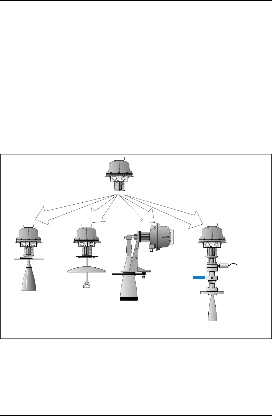
Transmitter Head
Parabolic
Antenna
Gauge,
RTG 2930
Still Pipe
Gauge,
RTG 2940
LPG/LNG
Gauge,
RTG 2960
Horn
Antenna
Gauge,
RTG 2920
W11W12
FOR
INTRINSICALLY
SAFE CIRCUITS
ONLY
"i"
3 Description of the Radar Tank Gauges
Depending on the type of tank connection unit that the Transmit-
ter Head is mounted on, there are four types of Radar Tank
Gauges:
• The Horn Antenna Gauge, RTG 2920, for fixed roof installa-
tion without still pipe.
• The Still Pipe Gauge, RTG 2940, for measuring in still pipes.
• The Parabolic Antenna Gauge, RTG 2930, for demanding
environments without still pipe.
• The LPG/LNG Gauge, RTG 2960, for liquid gas, LPG and
LNG.
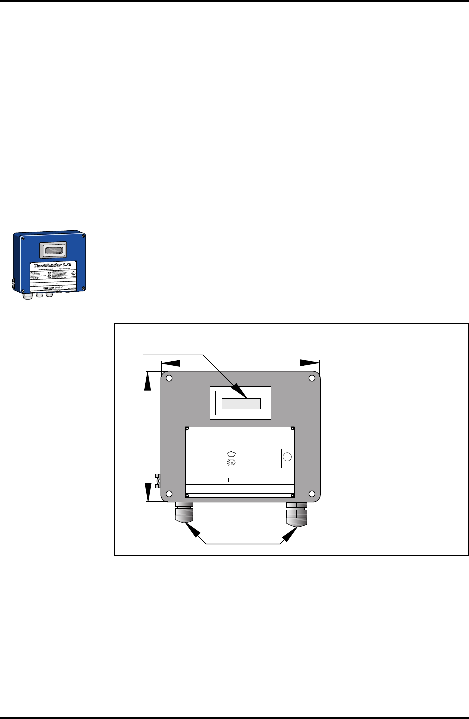
3.1 Transmitter Head
The same Transmitter Head is used on all four types of Radar Tank
Gauges.
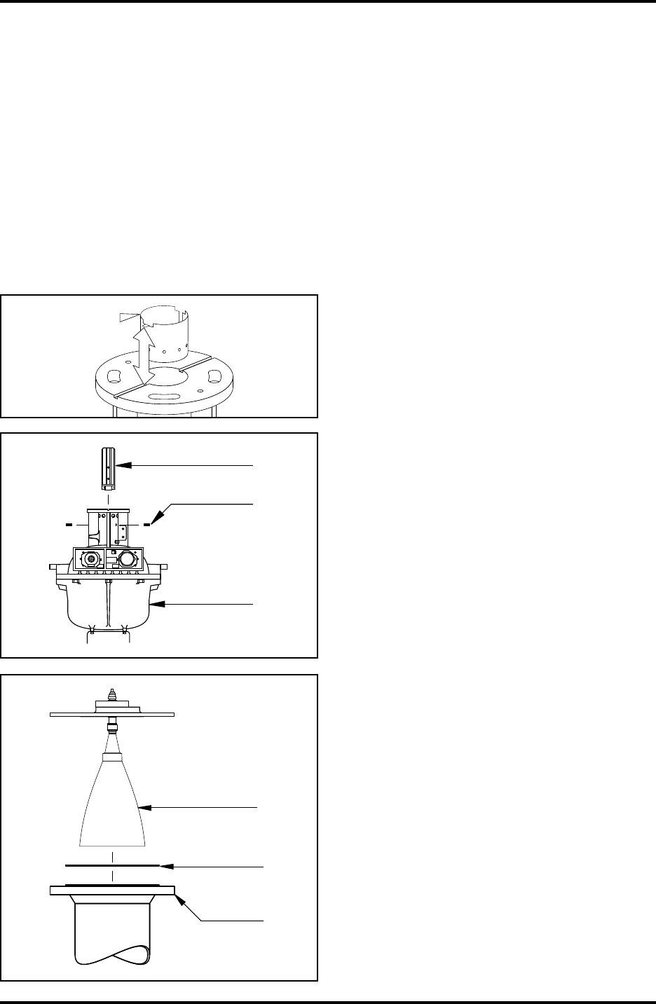
Figure 3.1 shows the Transmitter Head
Saab TankRadar L/2
13
US Version. Seventh edition, June 1995
Installation Manual
Figure 3.2 shows the Transmitter Head
3.1.1 Electronic Unit
The Electronic Unit is placed inside the safety enclosure of the
Transmitter Head. The Electronic Unit includes the microwave
unit, and cards for signal processing, data communication, and
power supply with transient protection.
A number of options require that cards are included in the Elec-
tronic Unit.
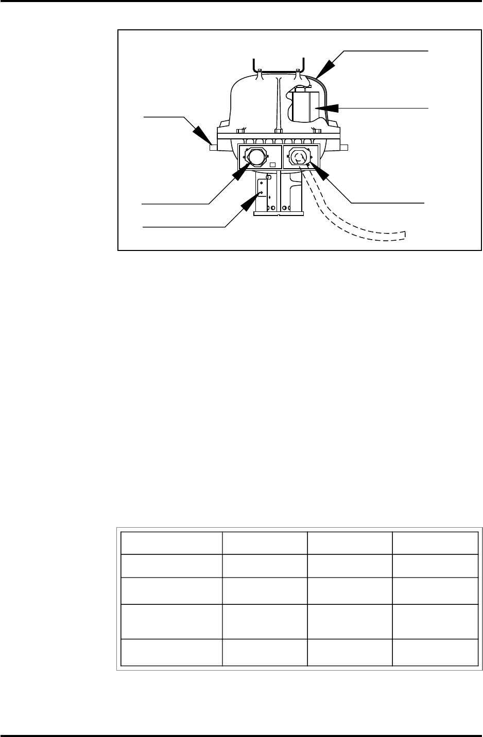
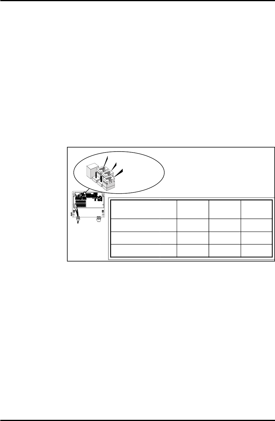
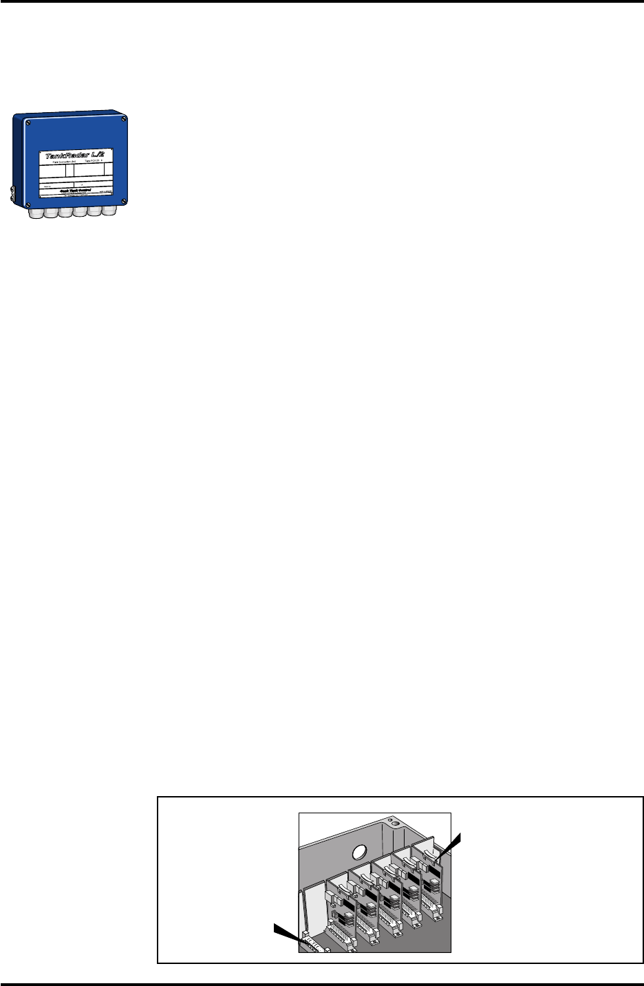
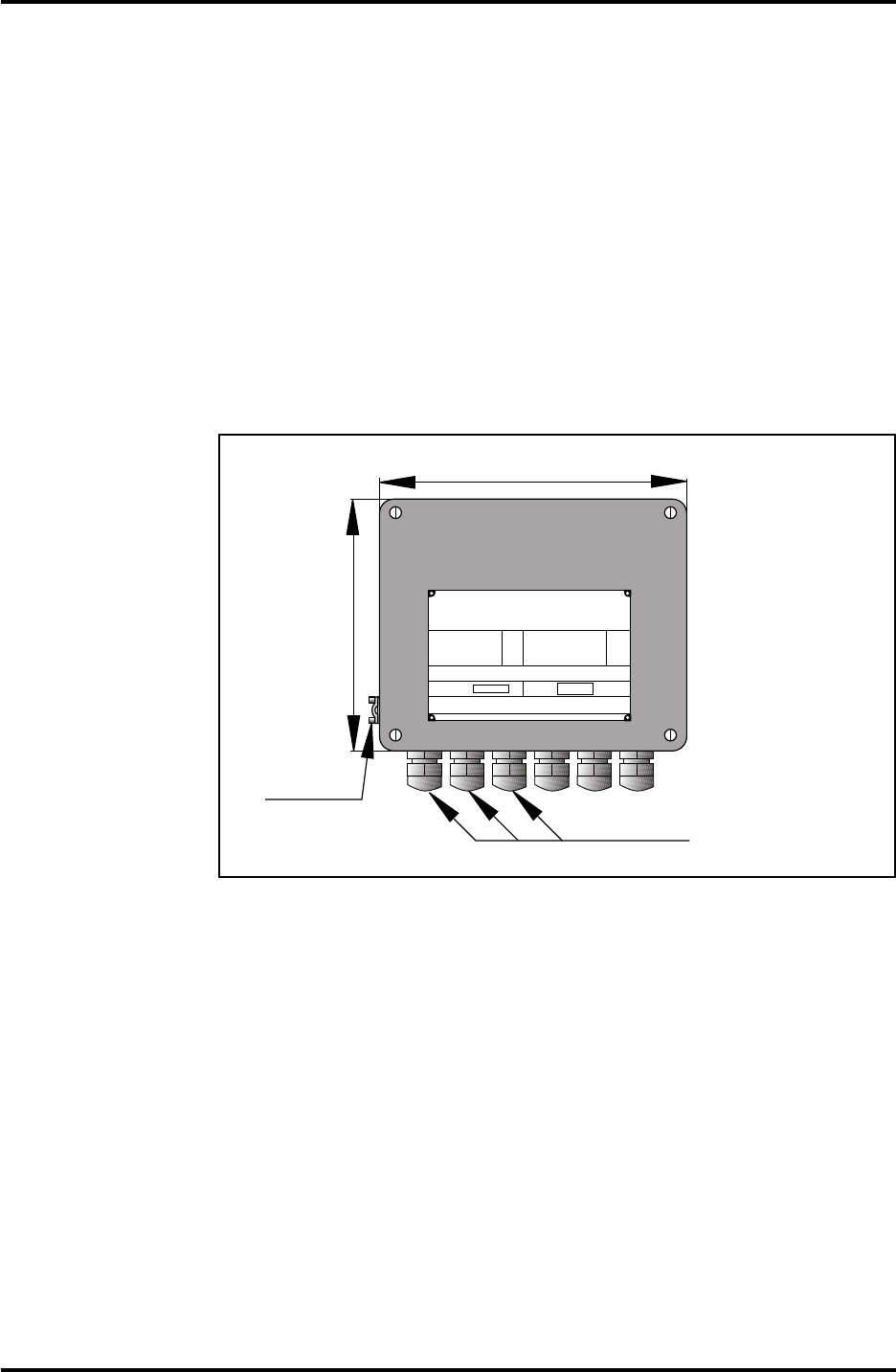
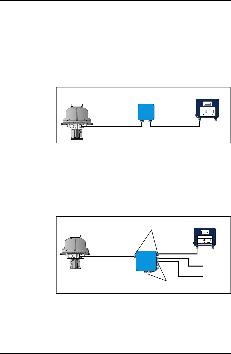
3.1.2 Cable Outputs
The Transmitter Head has one or two cable outlets. One is for the
non-intrinsically safe power connection and the connection to the
TRL/2 Bus. The other is for the intrinsically safe connection of the
optional Slave Data Acquisition Unit, and/or the optional analog
inputs and outputs of the Current Loop Card. The wires are
clearly marked with numbers and the designation of the wires is
shown on a printed plate at the cable outputs.
W11W12
FOR
INTRINSICALLY
SAFE CIRCUITS
ONLY
"i"
Intrinsically safe
connection for
Slave DAU
Safety enclosure
Electronic Unit
Mounting
pins for
Weather
Protection
Hood
Non-intrinsically
safe connection
for power and
TRL/2 Bus
Ground connection
Option W-12 Connection Barrier Unit Current Loop Card
Slave DAU 8-wire lead seal Required Not required
Current Loop Card
2 inputs + 2 outputs 12-wire lead seal Not required Required
Slave DAU and
Current Loop Card
2 inputs + 2 outputs 12-wire lead seal Required Required
Current Loop Card
3 inputs + 2 outputs 12-wire lead seal Not required Required
Table 3.1. The table describes what is required when the optional Slave
DAU and/or the optional Current Loop Card are included.
14
Saab TankRadar L/2
US Version. Seventh edition, June 1995
Installation Manual
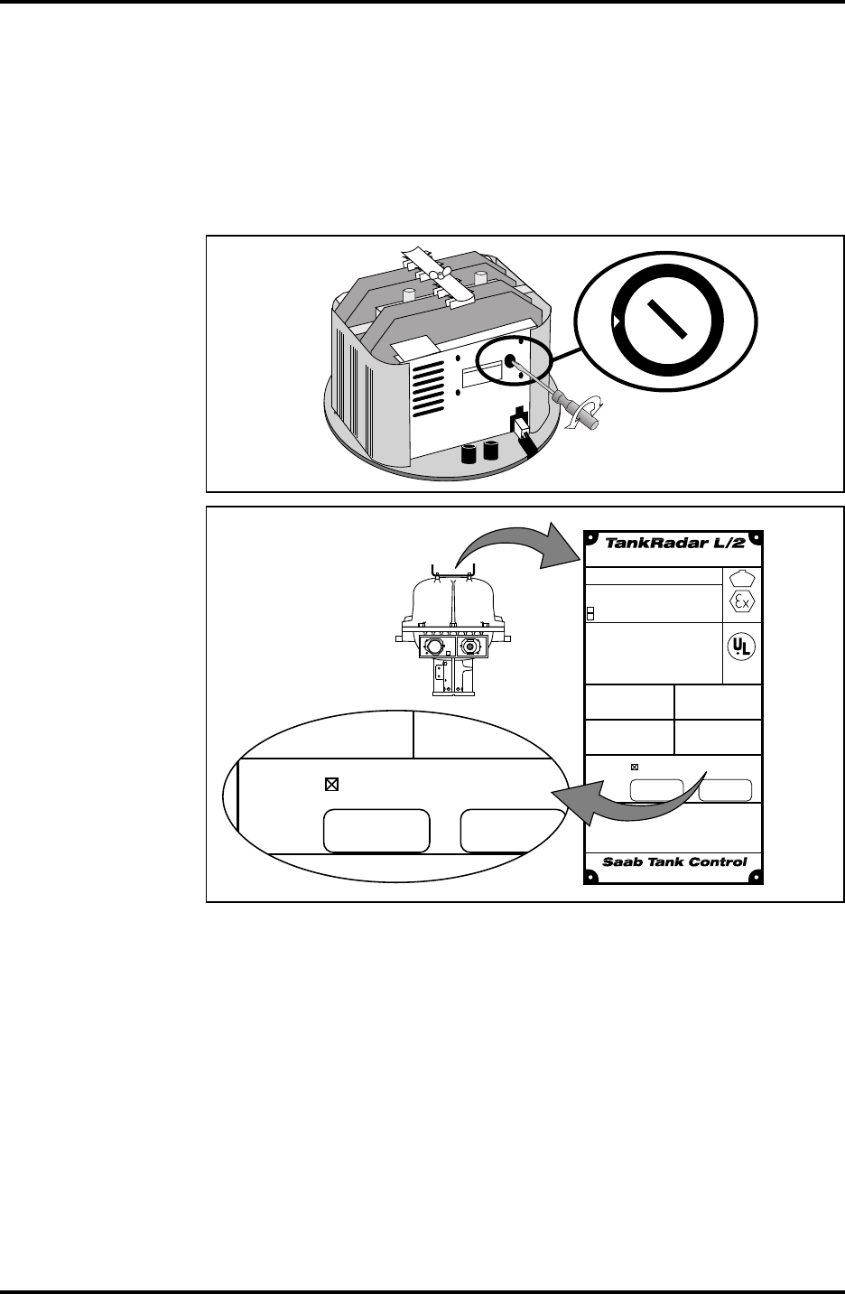
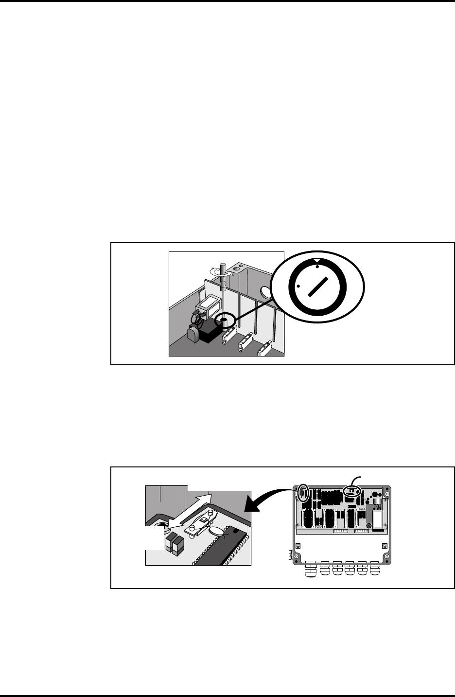
3.1.3 Power Supply to the Radar Tank Gauge
There is a switch on the Electronic Unit for setting of the power
supply to 115 V or 230 V. As standard the switch is set to 230 V.
To select supply voltage, remove the cover of the Safety Enclosure
and set the switch on the Electronic Unit to either 115 V or 230 V.
See figure 3.3
Figure 3.3.
Note: Do not turn
the switch all the
way around as it
may damage the
switch.
MAINS VOLTAGE SELECTOR
115V/230V
SELECTED VOLTAGE TO
BE MARKED ON OUTSIDE
NAMEPLATE
230 V
115 V
Mains wired for 230 VAC 0.4A
Mark Box if re-wired for 115 VAC 0.8A
Selector inside enclosure.
Serial no: UI:
CAUTION: To prevent ignition of hazardous
atmospheres, disconnect the device from the
supply circuit before opening. Keep assembly
closed when in operation.
Do not open while enrgized.
Ne pas ouvrir sous tension.
Hazardous Location Class I
Group C and D. (Intrinsically Safe
outputs Group A,B,C and D)
Temperature Coide T4.
Leads factory sealed. The device
provides intrinsically safe outputs
See control drawing 9150057-901
Ambient temperature -40 to + 65°C
Box marked when this enclosure
contains Associated Electrical
Apparatus. Component Certificate
BAS Ex91C2065U coded [EExia]IIC
BAS Ex93C2043U coded [EExia]IIB
EEx dIIB T4 T
amb
= -40 to +65°C
BASEEFA Ex91C1065X
Radar Unit Type TH 2000
Ex
A division of Saab Marine Electronics AB
MADE IN SWEDEN
LISTED 939U
Mains wired for 230 VAC 0.4A
Mark Box if re-wired for 115 VAC 0.8A
Selector inside enclosure.
Serial no: UI:
CAUTION: To prevent ignition of hazardous
atmospheres disconnect the device from th
W11W12
FOR
INTRINSICALLY
SAFE CIRCUITS
ONLY
"i"
RTG
name
plate
Mark the box on the
RTG name plate if the
power setting has been
changed to 115 VAC.
RTG
Figure 3.4.
Note: On the label
on top of the Trans-
mitter Head, there is
a box that must be
marked with an "X"
if you set the switch
to 115 V. See figure
3.3. Always check
this label before
connecting power to
the Electronic Unit.
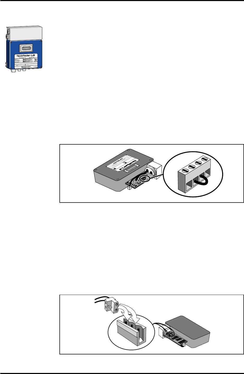
3.1.4 Barrier Unit Card, BU (Option)
The optional Barrier Unit Card is used when a Slave Data Acquisi-
tion Unit is connected to a Radar Tank Gauge. It provides intrinsi-
cally safe power and communication between the Slave DAU and
the RTG. The Barrier Unit is installed inside the Transmitter Head.
The Barrier Unit is connected to the Slave DAU through the Intrin-
sically Safe Connection W12 on the Radar Tank Gauge.
Note: Installation of the Barrier Unit Kit, the Current Loop Card or the
Metrological Seal may only be done by personnel from Saab Tank Con-
trol.
Saab TankRadar L/2
15
US Version. Seventh edition, June 1995
Installation Manual
3.1.5 Current Loop Card, CLC (Option)
The optional Current Loop Card provides intrinsically safe 4-20
mA inputs and outputs. The inputs can be used for example for
pressure sensors, while the outputs can be used for pointer instru-
ments or for output of a measured value as an analog signal.
If a Slave DAU is also connected, two 4-20 mA inputs and two 4-
20 mA outputs are available. If a Slave DAU is not connected, one
additional 4-20 mA input is available, although this transducer
must have its own intrinsically safe power supply.
When the optional Current Loop Card is used, the JB 12 Junction
Box from Saab Tank Control is recommended since the cables are
separated inside the box according to the requirements for intrin-
sic safety. See chapter 7.2.
W11W12
FOR
INTRINSICALLY
SAFE CIRCUITS
ONLY
"i"
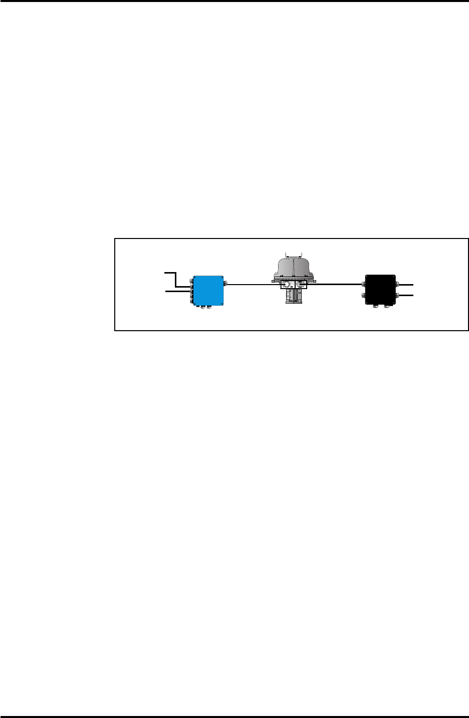
~2 m cable
with
protective
hose
Transmitter Head with
Current Loop Card
Signal
Power
230/115 V
~2 m cable
with
protective
hose
JB 12 JB 16
Analog
inputs
Analog
outputs
Figure 3.5 shows a Transmitter Head with a Current Loop Card.
3.1.6 Metrological Seal
The Metrological Seal consists of a rod that can activate a write-
enable switch from the outside of the Transmitter Head. This rod
can be sealed in the write-inhibit position to prevent unauthorized
changes in the database.
If there is no Metrological Seal mounted, then the Transmitter
Head is always in write-enable mode.
3.1.7 Installation Data for the Transmitter Head
Ambient operating temperature: -40°C to +65°C
(-40°F to +149°F)
Explosion protection Class 1, Div I, Groups C and D
(UL1203, UL913 USA) and
EEx d[ia] IIB T4 (EN50014,
EN50018 and EN50020 Europe)
Power Supply 115 or 230 VAC, +10% to -15%,
50-60 Hz, max. 80 W
Field bus TRL/2 Bus (FSK, half duplex,
two wires, galvanically iso-
lated, 4800 Baud)
16
Saab TankRadar L/2
US Version. Seventh edition, June 1995
Installation Manual
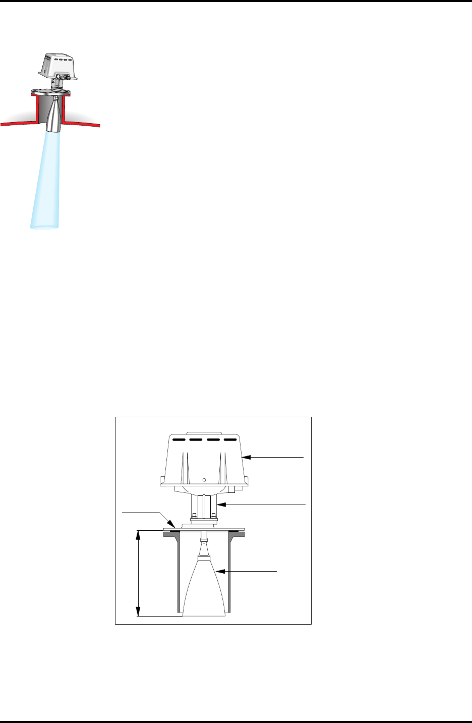
3.2 Description of the Horn Antenna Gauge, RTG 2920.
The Horn Antenna Gauge is designed for easy mounting in small
size openings on tanks with fixed roof. A flange with a diameter of
8" is enough to mount the RTG 2920.
The RTG 2920 is designed for measurement of a variety of oil
products and chemicals except for bitumen/asphalt and similar
products where the Parabolic Antenna Gauge RTG 2930 is recom-
mended.
The wide beam of the Horn Antenna Gauge is a disadvantage in
narrow tanks with internal structures. In such cases the Parabolic
Antenna Gauge is generally recommended.
The Horn Antenna Gauge is delivered with one of two types of
flanges. One flange is for straight mounting. The other flange is
used for inclined mounting.
See also chapter 10.1 for installation requirements for the Horn
Antenna Gauge.
3.2.1 Installation Data for RTG 2920
Operating temperature in tank Max. +150°C (+300°F)
Min. -40°C (-40°F)
Measuring range 0.85 to 30 m below flange
(2.7 to 66 ft.)
Pressure -0.5 to 2 bar
Total weight Appr. 20 kg (44 lbs.)
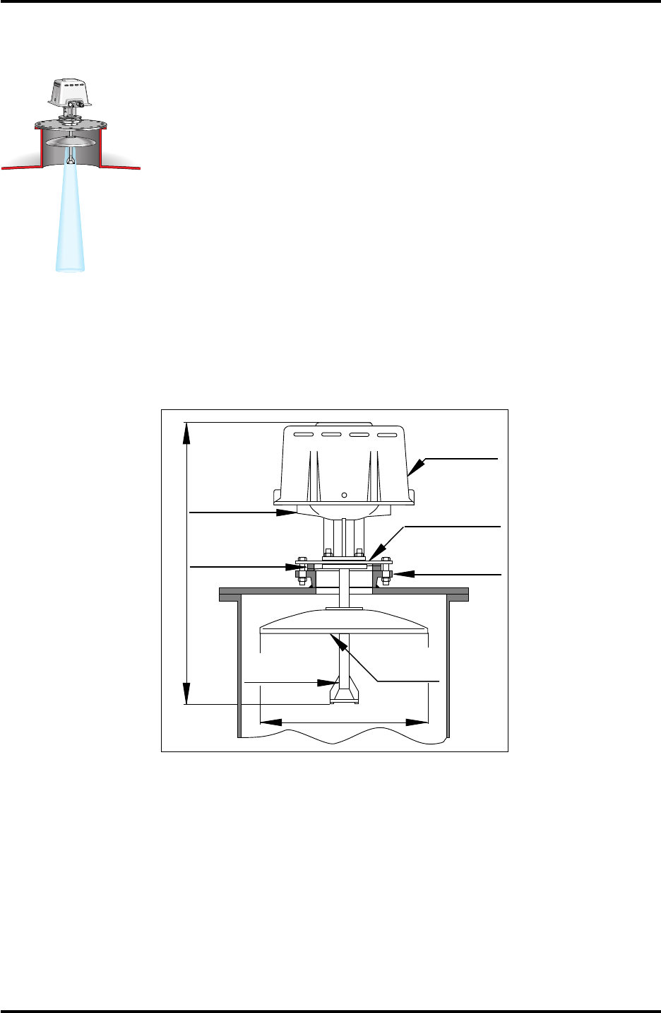
Socket size Min. 8"
Weather
Protection
Hood
Transmitter
Head
Cone
Closing
0.35 m
Figure 3.6 shows the Horn Antenna Gauge.
Saab TankRadar L/2
17
US Version. Seventh edition, June 1995
Installation Manual
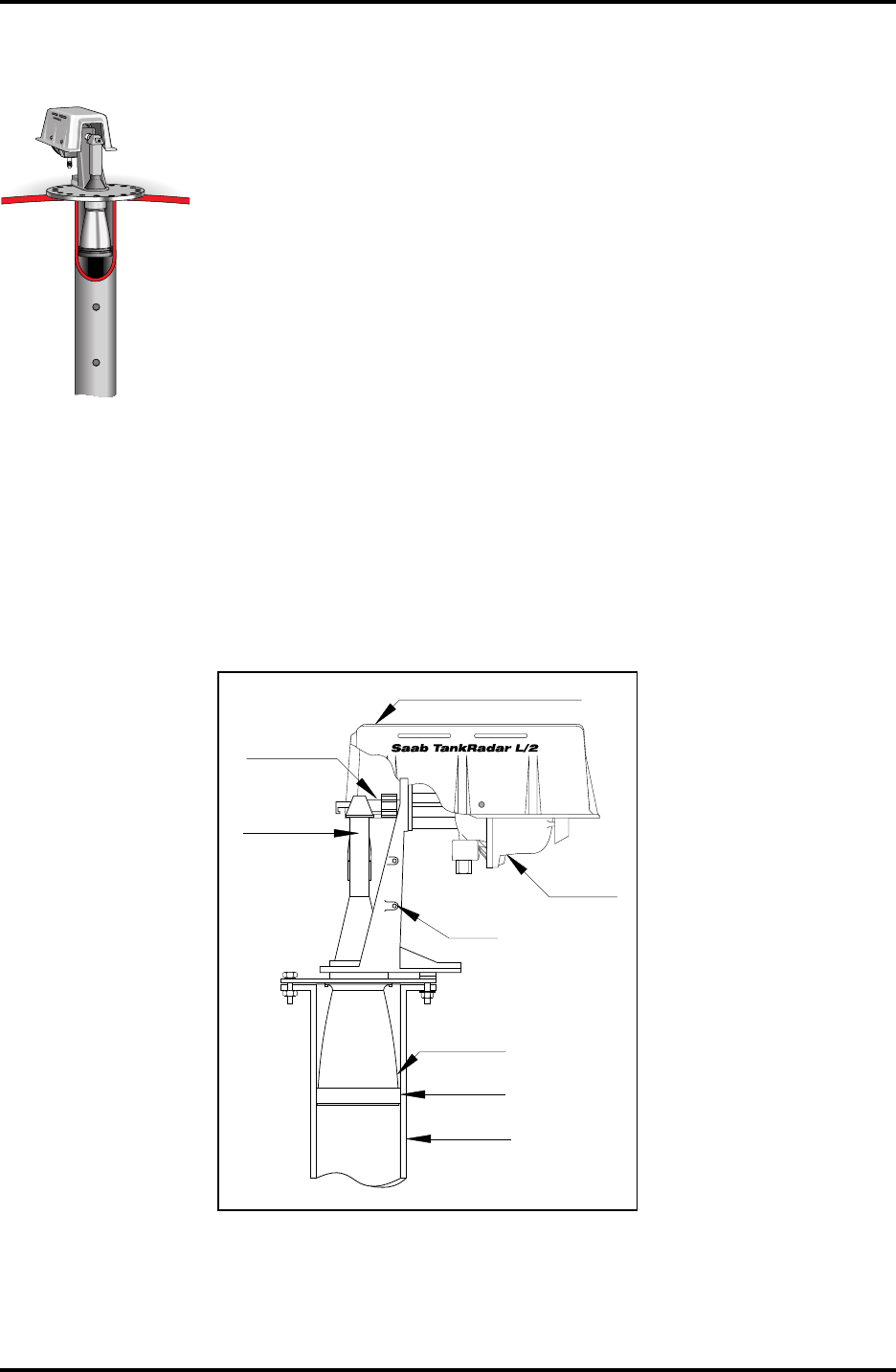
3.3 Description of the Parabolic Antenna Gauge, RTG 2930
The Parabolic Antenna Gauge RTG 2930 measures level of all
types of liquids, from light products to bitumen/asphalt. The
gauge is designed for mounting on tanks with fixed roofs and has
custody transfer accuracy.
The design of the parabolic antenna provides extreme tolerance
against sticky and condensing products.
See also chapter 10.2 for installation requirements for the Parabolic
Antenna Gauge.
3.3.1 Installation Data for RTG 2930
Operating temperature in tank Max. +230°C (+445°F)
Measuring range 0.8 to 40 m below flange
(2.7 to 131 ft.)
Pressure -0.5 to 2 bar
Total weight Appr. 25 kg (55 lbs.)
Socket size Min. 20"
Weather
Protection
Hood
Transmitter
Head Closing
Inclination
Device
Parabolic
Reflector
Antenna
Feeder
Adaptor
Flange
0.45 m
0.75 m
Figure 3.7 shows the Parabolic Antenna Gauge.
18
Saab TankRadar L/2
US Version. Seventh edition, June 1995
Installation Manual
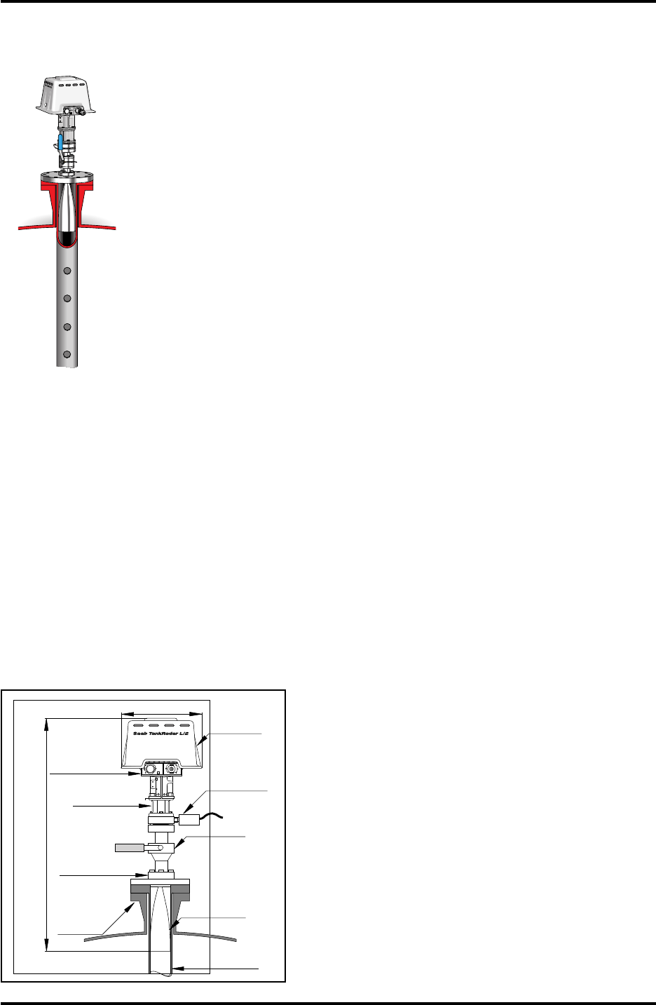
3.4 Description of the Still Pipe Gauge, RTG 2940
The Still Pipe Gauge is used on tanks with still pipes and with all
products suited for still pipes.
The gauge uses a low-loss radar propagation mode which virtu-
ally eliminates the influence of the still pipe condition. Measure-
ment is made with highest accuracy even when the pipe is old,
rusty and covered with deposits.
The Still Pipe Gauge fits 6", 8", 10" and 12" pipes. It can be
mounted on an existing still pipe and there is no need to take the
tank out of operation during installation.
See also chapter 10.3 for installation requirements for the Still Pipe
Gauge.
3.4.1 Installation Data for RTG 2940
Operating temperature in tank Max. +230°C (+445°F)
Measuring range 0 to 40 m from cone end
(0 to 131 ft.)
Pressure -0.2 to +0.5 bar
Total weight Appr. 20 kg (44 lbs.)
Still pipe dimension 6", 8", 10" or 12". See table 10.1
for information on schedules.
Transmitter
Head
Transition
Cone
Waveguide
Unit
Waveguide
Connection
Stand
Sealing
Weather Protection Hood
Still pipe
Figure 3.8 shows the Still Pipe Gauge.
Saab TankRadar L/2
19
US Version. Seventh edition, June 1995
Installation Manual
3.5 Description of the LPG/LNG Gauge, RTG 2960
The RTG 2960 is designed for level measurement in LPG and LNG
tanks. A still pipe is required for the measurement. It prevents a
wavy or boiling surface from disturbing the measurement. Radar
signals are transmitted inside the pipe towards the surface.
The pressure sealing is a quarts window approved for use in
pressure vessels. As standard the gauge is also equipped with a
fire-proof block valve and a vapor space pressure sensor.
The LPG/LNG Gauge is available in three different versions, a 150
PSI version, a 300 PSI version and a 600 PSI version.
The patented reference pin function enables verification of mea-
surement without opening the tank. There is a Reference Pin at the
top of the still pipe and a Reference Plug made of epoxy resin at
the bottom. If epoxy can not be used in the tank, two or three
reference pins can be used without the Reference Plug. By setting
the gauge into "test mode" it measures against these references
and compares with the actual distances to these references that
were stored during installation.
See also chapter 10.4 for installation requirements for the LPG/
LNG Gauge.
3.5.1 Installation Data for RTG 2960
Operating temperature in tank Stainless steel flange -66°C to +
90°C (67°F to 194°F)
Measuring range 0 to 40 m from cone end
(0 to 131 ft.)
Pressure Up to 25 bar (375 PSI)
Still pipe dimension 4" Sch. 10 or 100 mm inner
diameter.
Total weight 150 PSI – appr. 38 kg (84lbs)
300 PSI – appr. 48 kg (106 lbs)
600 PSI – appr. 68 kg (150 lbs)
W11W12
FOR
INTRINSICALLY
SAFE CIRCUITS
ONLY
"i"
6" Existing
pressure
vessel
flange
1.0 m
0.35 m
Lower Flange
Weather
Protection
Hood
Transmitter
Head
Valve
Pressure
Transducer
Pipe Cone
4" or ø100 mm
Still Pipe
Housing
Figure 3.9 shows
the LPG/LNG
Gauge.
20
Saab TankRadar L/2
US Version. Seventh edition, June 1995
Installation Manual
4 Description of the Data Acquisition Units
The Data Acquisition Unit, DAU, is a complement to the Radar
Tank Gauge and it can interface various external sensors and
actuators. There are two versions of the DAU, the Slave DAU and
the Independent DAU. Both types have interfaces for temperature
measurement.
Figure 4.1 shows the Slave DAU and the Independent DAU.
4.1 Connection of the Sensors
The DAUs can connect up to 14 RTDs (Resistance Temperature
Detectors) on the X21 terminal on the motherboard. See figure 4.2.
Under the lid of the Data Acquisition Unit there are instructions
printed as to how to connect the sensors and transducers.
43
40
37
34
31
28
25
22
19
16
13
10
7
4
1
44
41
38
35
32
29
26
23
20
17
14
11
8
5
2
45
42
39
36
33
30
27
24
21
18
15
12
9
6
3
Connect
temperature
sensors
DAU
Connect Reference
Resistor to terminals
43, 44 and 45.
Figure 4.2 shows the wire terminals for the temperature sensors.
Saab TankRadar L/2
21
US Version. Seventh edition, June 1995
Installation Manual
4.2 Selecting the Temperature Range
The multiplexer for the RTDs has two different amplification
factors which are jumper selected. It is also possible to provide an
offset to the measured signal by adding a current to it. The ampli-
fication is selected on the X1 and X2 and the offset is selected on
the X3 according to the table in figure 4.3. The standard setting is
from -50°C to +125°C. The database setting of the temperature
range in the Operator’s Interface (OPI) or the Configuration Soft-
ware (COS) must correspond to the setting of the jumpers.
A high precision reference resistor must be connected to the X21
terminal to positions 43, 44 and 45. Depending on the temperature
range stated in the Required System Information form, one out of
three different reference resistors is chosen and connected. See
figure 4.2 and spare parts list in the Service Manual.
X1 - OPEN
X2 - OPEN
X3 - CLOSED
Temperature Range
Pt 100 X1 X2 X3
-50 - +125 °C OPEN OPEN CLOSED
-50 - +300 °C CLOSED CLOSED CLOSED
-200 - +150 °C CLOSED CLOSED OPEN
Figure 4.3 shows the selection of temperature range.
4.3 Local Readout Display
Both versions can, as an option be equipped with a Local Readout
Display showing the product level as well as the parameters mea-
sured by the DAU itself.
Installation data for Local Readout Display
Ambient operating temperature: -30°C (-22°F)
4.4 Write Enable/Inhibit Switch
In order to enable programming of the EEPROM, the S1 switch
must be set in the position, towards the block terminals. The
switch can be locked and sealed in the write inhibit position using
a wire through the clevis pins. See figure 6.3.
22
Saab TankRadar L/2
US Version. Seventh edition, June 1995
Installation Manual
4.5 Common Installation Data for Both DAUs
Ambient operating temperature: -40°C to +65°C (-40°F to +149°F)
Temperature Sensors Pt 100 or Cu 100
Number of sensor elements Max. 14 per DAU
Temperature measuring range Range 1: -50 to +125 °C
Range 2: -50 to +300 °C
Range 3: -200 to +150°C
4.6 Description of the Slave Data Acquisition Unit, DAU 2100
The Slave DAU is intrinsically safe and is connected to the Radar
Tank Gauge on the same tank. It receives its power supply and
communicates via the Barrier Unit Card in the Radar Tank Gauge.
4.6.1 Installation Data for DAU 2100
Explosion protection Class 1, Div I, Groups A,B,C
and D (UL913 USA) and
EEx ia IIC T4 (EN50020 Europe)
Power Supply Intrinsically safe supply from
Radar Tank Gauge
Field bus Intrinsically safe local line from
Radar Tank Gauge
LCD Display for
Local Readout
Cable Outputs
0.23 m
0.28 m
Saab Tank Control
TankRadar L /2
EEx ia II C T4
Tamb = -40° to +65°C
BASEEFAEx91C2069
Umax:in = 28 VDC Wmax:in = 1.3 W
Imas:in = 394 mADC
Ceq = 0 Leq = 0
Serial no: UI:
A division of Saab Marine Electronics AB
For intrinsically safe circuits only
Data Acquisition Unit Type DAU 2130
Hazardous Location Class I Gorup C
and D. Temperature Code T4. The device
provides intrinsically safe outputs.
See control drawing 9150 057-901
Warning: any substitution of any components
may impair intrinsic safety.
See service manual
Ambient temperature -40° to +65°CListed 9390
UL
Ex
MADE IN SWEDEN
©
Figure 4.4 shows the Slave Data Acquisition Unit.
Saab TankRadar L/2
23
US Version. Seventh edition, June 1995
Installation Manual
4.7 Description of the Independent Data Acquisition Unit
Warning: The DPS board inside the flameproof enclosure of the Indepen-
dent DAU contains powered circuits on easily accessible components.
In addition to the temperature measurement, the Independent
DAU has four analog inputs and eight digital inputs as well as
four relay outputs. The Independent DAU communicates directly
on the TRL/2 Bus.
4.7.1 Power Supply
Power supply voltage to the Independent DAU is selected as
either 115 V or 230 V. The voltage is selected by jumpers in X5, a 4-
pole screw terminal. The jumper is set to 230 V as standard. See
figure 4.5.
Note: The setting of the voltage is marked on the nameplate. If the switch
is set to 115 V, mark the box on the nameplate: “Mark box If re-wired for
115 VAC”.
1234
TankRadar L/2
Saab Tank Control
UL
Ex
©
Data Acquisition Unit Type DAU 2130
A division of Saab Marine Electronics AB
For intrinsically safe circuits only
EEx ia C T4
BASEEFA Ex91C2069
LISTED 939U
MADE IN SWEDEN
T
amb
U=28 W=1.3
C=0 L =0
max:in
max:in
=394
max:in
eq eq
I
VDC W
mADC
=-40° to +65°C
UI:
Serial no:
Ambient temperature -40° to +65°C
See service manual
may impair intrinsic safety
Warning: any substitution of components
See control drawing 9150 057-901
provides intrinsically safe outputs.
and D. Temperature Code T4. The device
Group C
Hazardous Location Class
1234
Figure 4.5 shows the voltage setting. Set 2-3 for 230 VAC. Set 1-2 and 3-
4 for 115 VAC.
4.7.2 Relays (Optional)
There are four relays on the Independent DAU. The relays can be
activated by the level measured by the associated RTG or by any
of the parameters measured by the Independent DAU itself.
The optional relays of the Independent DAU can be selected as
either normally open or normally closed. This is done by setting a
two way cable connector in alternative positions in a three pin
header connector. See figure 4.6.
NO - NC
Figure 4.6. Plug
connector in appro-
priate position for
normally open or
normally closed
operation of the
relay.
24
Saab TankRadar L/2
US Version. Seventh edition, June 1995
Installation Manual
4.7.3 Installation Data for DAU 2130
Explosion protection Class 1, Div I, Groups C and D
(UL1203, UL913 USA) and
EEx d[ia] IIB T4 (EN50014,
EN50018 and EN50020 Europe)
Power Supply 115 or 230 VAC, +10% to -15%,
50-60 Hz, max. 10 W
Field bus TRL/2 Bus (FSK, half duplex,
two wires, galvanically iso-
lated, 4800 Baud)
Current inputs 4-20 mA. Intrinsically safe.
Number of current inputs Max. 4, multiplexed, only one is
powered at a time
Number of status and frequency
inputs Max. 8. Intrinsically safe.
Number of relay outputs Max. 4
Relay contact rating 250 VAC / 5A (resistive load)
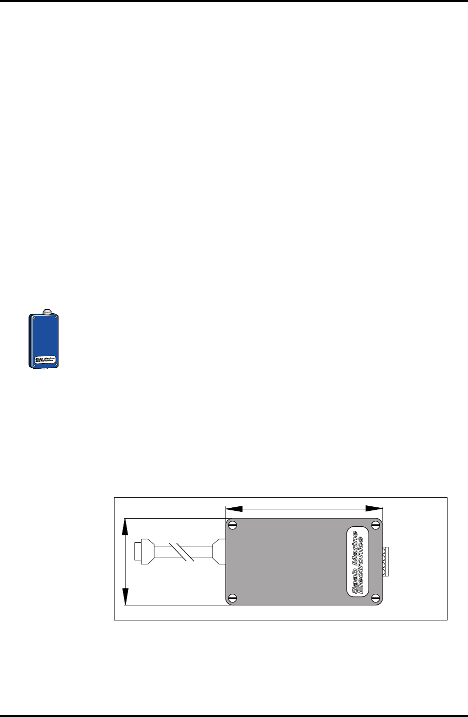
5 Description of the Field Bus Modem, FBM 2170
The Field Bus Modem, FBM, is a converter between RS-232C and
the TRL/2 Bus. It is used for connecting a PC with OPI (or COS) to
the TRL/2 Bus.
Note: No explosion protection is provided, so the Field Bus Modem must
be installed in a non-hazardous area.
5.1 Installation Data for FBM 2170
Power supply From AC/DC converter sup-
plied by Saab Tank Control. 6-
15 V, 10 mA).
Cable to PC Supplied by Saab Tank Control
Explosion protection None
Saab Marine
Electronics
X2 X1
Conn.
to PC
Conn. to
TRL/2
Field Bus
0.065 m
0.115 m
Figure 5.1 shows the Field Bus Modem.
Saab TankRadar L/2
25
US Version. Seventh edition, June 1995
Installation Manual
6 Description of the Field Communication Unit,
FCU 2160
The Field Communication Unit continuously polls data from the
Radar Tank Gauges and the Data Acquisition Units and stores it in
a buffer memory. The Field Communication Unit is the master on
the Field Bus but acts as a slave on the Group Bus.
Note: No explosion protection is provided, so the Field Communication
Unit must be installed in a non-hazardous area.
6.1 Communication Ports
The Field Communication Unit has six communication ports, X1
to X6. The ports can be individually configured as either Group
Bus or Field Bus ports. There can be maximum four Group Buses
or four Field Buses at the same time. Maximum configuration can
be 2+4, 3+3 or 4+2 buses of each kind. However, ports X5 and X6
are never configured as Field Bus ports, while the X1 and X2 ports
are never configured as Group Bus ports.
As standard the Field Communication Unit is delivered with six
FCM interface boards for four Field Bus ports and two Group Bus
ports.
The table below shows the maximum configurations of an ex-
tended FCU:
Ports: X1 X2 X3 X4 X5 X6
Alternative 4+2: FB FB FB FB GB GB
Alternative 3+3: FB FB FB GB GB GB
Alternative 2+4: FB FB GB GB GB GB
There are also two jumper connectors delivered with each unit.
These can be connected to the X5 and/or X6 for RS-232C Group
Bus communication. See figure 6.1.
Any of the FCM interface boards can be replaced with FCI inter-
face boards for RS-485 communication.
Note: The wire terminals 1 and 3 respectively 2 and 4 on FCM board
connector are parallel connected. See installation drawing.
X1
X2
X3
X4
X5
X6
TRL/2 Bus Interface
boards, FCM boards
Jumper for
RS-232C
Figure 6.1 shows the
bus ports on the
Field Communica-
tion Unit.
26
Saab TankRadar L/2
US Version. Seventh edition, June 1995
Installation Manual
6.2 FCU Enclosure
As standard the Field Communication Unit is shipped in a
weather protected, wall-mounted box of the same type as the Data
Acquisition Unit. The Field Communication Unit is built on a
Printed Circuit Board and may be delivered as such for mounting
within a customer supplied enclosure.
6.3 FCU Power Supply
There is a switch to select the supply voltage to either 115 V or 230
V. The switch is set to 230 V as standard. See figure 6.2.
If the switch is set to 115 V, mark the box on the nameplate: “Mark
box If re-wired for 115 VAC”.
NOTE: Do not turn the switch all the way around as it may damage the
switch.
230 V
115 V
Figure 6.2. Setting of the supply voltage to the FCU.
6.4 Write Inhibit/Enable Switch
There is a write inhibit switch in the FCU. It can be locked in the
write inhibit position by securing a locking plate with a wire
through the clevis pins, see figure 6.3.
230 V
115 V
Write inhibit
Write
enable
Reset switch
Figure 6.3. Write enable/inhibit switch.
Saab TankRadar L/2
27
US Version. Seventh edition, June 1995
Installation Manual
6.5 Installation Data for FCU 2160
Ambient operating temperature: -40°C to +65°C
(-40°F to +149°F)
Power Supply 115 or 230 VAC, +10% to -15%,
50-60 Hz, max. 80 W
Group bus interface TRL/2 Bus, RS-232 or RS-485
Field bus interface TRL/2 Bus. Max 16 units on
one port
Ambient operating temperature: -40°C to +65°C
(-40°F to +149°F)
Explosion protection None
Number of RTGs and/or Independent DAUs Max. 32 RTGs and
32 DAUs
Cable Outputs
Ground
Connection
Saab Tank Control
TankRadar L/2
Serial no: UI:
A division of Saab Marine Electronics AB
Field Connection Unit Type FCU 2160
MADE IN SWEDEN
0.23 m
0.28 m
Figure 6.4. The Field Communication Unit.
28
Saab TankRadar L/2
US Version. Seventh edition, June 1995
Installation Manual
7 Description of the Junction Boxes
Saab Tank Control can supply a series of junction boxes for the
connection of the various units in the TankRadar L/2 system.
7.1 Junction Box JB 8 for Connection of RTG to Slave DAU
The JB 8 should only be used for intrinsically safe connections. It is
used when a Slave DAU is located more than 1.6 m away from the
RTG. It contains eight terminals, two holes for PG 16 glands, one
PG 16 gland for cable diameter 11-15 mm.
W11W12
FOR
INTRINSICALLY
SAFE CIRCUITS
ONLY
"i"
2 pcs PG 16
~ 2 m wires with
protective hose Cable
DAU
TH
Saab Tank Control
TankRadar L/2
EEx ia II C T4
Tamb = -40° to +65°C
BASEEFAEx91C2069
Umax:in = 28 VDC Wmax:in = 1.3 W
Imas:in = 394 mADC
Ceq = 0 Leq = 0
Serial no: UI:
A division of Saab Marine Electronics AB
For intrinsically safe circuits only
Data Acquisition Unit Type DAU 2130
Hazardous Location Class I Gorup C
and D. Temperature Code T4. The device
provides intrinsically safe outputs.
See control drawing 9150 057-901
Warning: any substitution of any components
may impair intrinsic safety.
See service manual
Ambient temperature -40° to +65°CListed 9390
UL
Ex
MADE IN SWEDEN
©
JB 8
Figure 7.1 shows the JB 8 Junction Box.
7.2 Junction Box JB 12 for Connection of RTG (with CLC) to
Slave DAU
The JB 12 should only be used for intrinsically safe connections. It
is used when a Current Loop Card is included in the RTG. It con-
tains 12 terminals, various holes for glands from PG 13.5-PG 16.
Six glands PG 13.5 for cable diameters 11-15 mm are included. See
also chapter 3.1.5.
W11W12
FOR
INTRINSICALLY
SAFE CIRCUITS
ONLY
"i"
6 pcs PG 13.5
~ 2 m wires with
protective hose Cable
DAU
TH 2 pcs PG 16
Analog
inputs
Analog
outputs
JB 12
Saab Tank Control
TankRadar L/2
EEx ia II C T4
Tamb = -40° to +65°C
BASEEFAEx91C2069
Umax:in = 28 VDC Wmax:in = 1.3 W
Imas:in = 394 mADC
Ceq = 0 Leq = 0
Serial no: UI:
A division of Saab Marine Electronics AB
For intrinsically safe circuits only
Data Acquisition Unit Type DAU 2130
Hazardous Location Class I Gorup C
and D. Temperature Code T4. The device
provides intrinsically safe outputs.
See control drawing 9150 057-901
Warning: any substitution of any components
may impair intrinsic safety.
See service manual
Ambient temperature -40° to +65°CListed 9390
UL
Ex
MADE IN SWEDEN
©
Figure 7.2 shows the JB 12 Junction Box.
Saab TankRadar L/2
29
US Version. Seventh edition, June 1995
Installation Manual
7.3 Junction Box JB 16 for Connection to RTG and Independent DAU
The JB 16 is an EEx "e" approved junction box, used for connecting
power and TRL/2 Bus to the RTG and the Independent DAU. It
contains 16 terminals, a flexible hose for the cabling to the RTG or
DAU, a mounting plate and various holes for glands from PG16-
21. Four glands are included for cable diameters 8-18 mm.
7.4 Junction Box JB 36 for Connection of Temperature Sensors
W11W12
FOR
INTRINSICALLY
SAFE CIRCUITS
ONLY
"i"
~2 m wires with
protective hose
Independent
DAU
TH
6 pcs PG 21
JB 16 for
Relay Output
Signal
Power 230/115 V
~2 m wires
with
protective
hose
JB 16
JB 16
Saab Tank Control
TankRadar L/2
EEx ia II C T4
Tamb = -40° to +65°C
BASEEFAEx91C2069
Umax:in = 28 VDC Wmax:in = 1.3 W
Imas:in = 394 mADC
Ceq = 0 Leq = 0
Hazardous Location Class I Group A, B, C
and D. Temperature Code T4.
Intrinsically safe for use in connection
with Radar Unit TH 2000- TH 2014.
See control drawing 9150 057-901
Warning: any substitution of components
may impair intrinsic safety
See service manual
Ambient temperature -40° to +65°C
Serial no: UI:
A division of Saab Marine Electronics AB
For intrinsically safe circuits only
Data Acquisition Unit Type DAU 2100
Listed 9390
UL
Ex
MADE IN SWEDEN
©
Figure 7.3 shows
the JB 16 junction
Box.
The JB 36 is used for the intrinsically safe connection of up to 14
temperature sensors to a DAU.
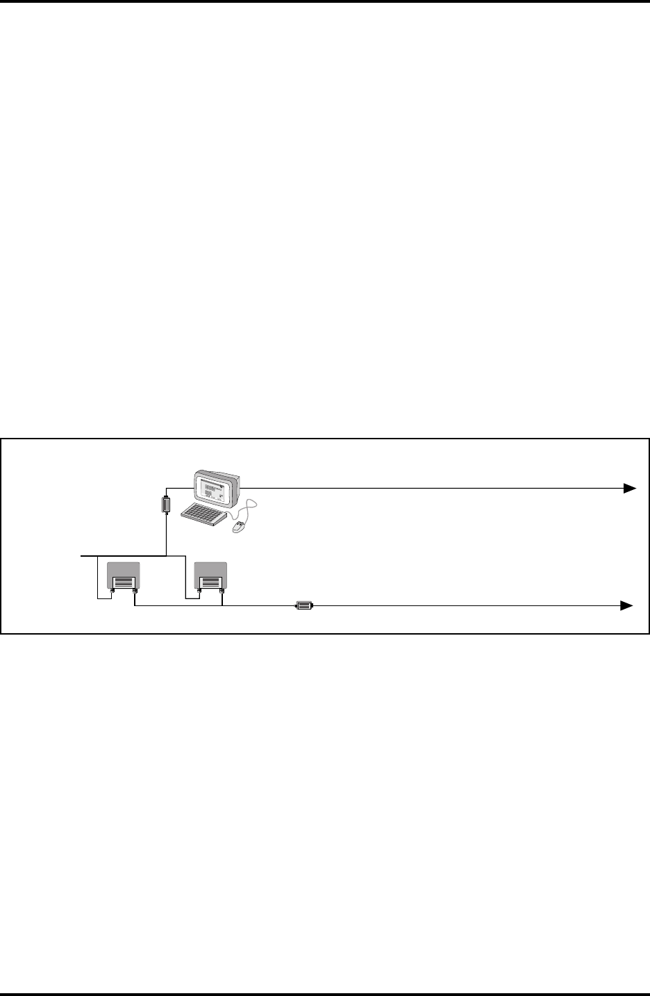
8 Connection to a Plant Host Computer (Plant DCS)
DAU
2 pcs PG 21
1 pc PG 16
Tempsensor
Pt100 - up to 12 sensors
Cu100 - up to 14 sensors
Cable
Saab Tank Control
TankRadar L/2
EEx ia II C T4
Tamb = -40° to +65°C
BASEEFAEx91C2069
Umax:in = 28 VDC Wmax:in = 1.3 W
Imas:in = 394 mADC
Ceq = 0 Leq = 0
Serial no: UI:
A division of Saab Marine Electronics AB
For intrinsically safe circuits only
Data Acquisition Unit Type DAU 2130
Hazardous Location Class I Gorup C
and D. Temperature Code T4. The device
provides intrinsically safe outputs.
See control drawing 9150 057-901
Warning: any substitution of any components
may impair intrinsic safety.
See service manual
Ambient temperature -40° to +65°CListed 9390
UL
Ex
MADE IN SWEDEN
©
JB 36
Figure 7.4 shows
two alternative
connections of the
JB 16 Junction Box.
30
Saab TankRadar L/2
US Version. Seventh edition, June 1995
Installation Manual
A host computer can be connected either to a PC with OPI Soft-
ware or directly to the Field Communication Units (FCUs).
The TRL/2 system can be connected to all major DCS systems,
such as Foxboro, Honeywell, Rosemount and Yokogawa. New
interfaces can be developed on request. For a complete list of the
available interfaces, please contact Saab Tank Control or one of its
representatives.
8.1 Connect to the FCU for Quick Updates
When a host computer is connected to one or several FCUs, mea-
sured data such as level, average temperature, pressure, etc. can be
transferred to the host system. If the host system has inventory
functions, a connection directly to the FCUs is recommended.
8.2 Connect to OPI/2 for Inventory Data
When a host computer is connected to the OPI/2, calculated data
such as volume, mass and density can be communicated in addi-
tion to the measured data mentioned in chapter 8.1 above.
9 Installation Schedule
FCU
Operator's
Interface
TRL/2 Group Bus
FCU
Measured data:
Level, Temperature, Pressure, etc.
Calculated data:
Volume, Mass, Density, etc.
FBM
FBM Measured data:
Level, Temperature, Pressure, etc.
0
0
0
0.200
Cancel
Value Entry
Enter New Tank
Tank1
Value Hi Lim Lo Lim HH Lim LL Lim
Temp Avg
Level
Delay Hyst
Temp Avg
Level
Pressure
Pressure
Leak Limit
Enable
Auto
Auto
Auto
18.000
120.0
2.0
2.000
80.0
0.0
20.000 1.000
5.0
0.5
0.200
Figure 8.1 shows two different ways of connecting a host computer to the TRL/2 system.

Saab TankRadar L/2
31
US Version. Seventh edition, June 1995
Installation Manual
1. Customer receives the Installation Manual with the Required
System Information Form.
2. The completely filled in Required System Information Form,
tank farm layout drawings and cabling drawings are sent to
Saab Tank Control representative 1-3 months prior to deliv-
ery, depending on system size.
3. The Installation drawings are reviewed and approved by
Saab Tank Control or Saab Tank Control representative.
Allow approximately 2 weeks for review and return.
4. Inspection at Saab Tank Control before delivery (when re-
quested).
5. Customer receives and installs the TRL/2 System according
to the Installation Manual.
6. Data sheets are completed and a system configuration chart
are made by the customer as a preparation for the start up of
the system. See Service Manual for instructions.
7. System is started up by customer (after completed training)
or a Saab Tank Control Representative according to Service
Manual.
8. Send Commissioning Check List to Saab Tank Control.
32
Saab TankRadar L/2
US Version. Seventh edition, June 1995
Installation Manual
10 Requirements on the Installation of the Radar Tank
Gauges
To achieve precise and trouble free measurement, it is very impor-
tant to mount the Radar Tank Gauge correctly on the tank.
Please note that if an ullage plug is required, it has to be installed
separately as there is no ullage plug on the Horn Antenna Gauge
or the Parabolic Antenna Gauge.
Note: Please see the installation drawings for more information. There is
a list of drawings in chapter 13.
10.1 Requirements for the Horn Antenna Gauge, RTG 2920
The Horn Antenna Gauge, RTG 2920, must be installed so that
there are no pipes or other obstacles that could prevent the radar
beam to reach the bottom unobstructed. Please refer also to the
mechanical installation drawing for more information on the
installation requirements of the Horn Antenna Gauge.
See installation drawing for requirements on service space.
Note: Levels closer than approximately 850 mm from the flange, cannot
be measured with the highest accuracy.
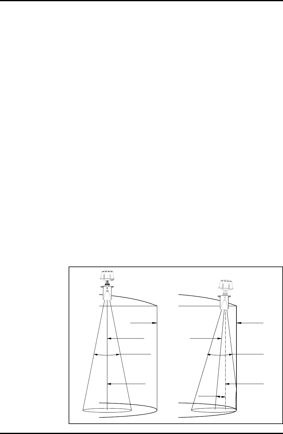
10.1.1 Free Space Requirement
The radar beam spreads over 30°. There are two flanges available
for the Horn Antenna Gauge. One inclines the gauge 4° and the
other is horizontal. See installation drawing for flange dimensions.
If the wall would intrude into the 30° radar beam with a vertical
antenna axis, the 4° flange has to be used so that the radar beam is
Antenna
axis
Tank
wall
Vertical
plumb
line
4° ± 1°
30° radar
beam
Antenna
axis
Tank
wall
Vertical
plumb
line
30° radar
beam
Figure 10.1 shows
the free space re-
quirements for the
Horn Antenna
Gauge.
Saab TankRadar L/2
33
US Version. Seventh edition, June 1995
Installation Manual
directed away from the wall. This inclination is necessary to en-
sure maximum accuracy.
If the wall does not intrude into the 30° radar beam when the
antenna axis is vertical, the horizontal flange can be used.
For special cases, where the maximum accuracy is not necessary,
the horizontal flange can be used even when the wall intrudes into
the radar beam. In doubtful cases, please contact Saab Tank Con-
trol or one of its representatives.
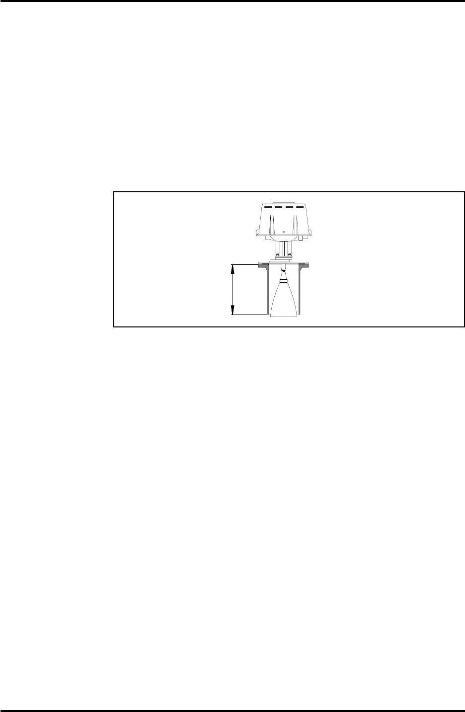
10.1.2 Socket Requirement
Maximum height of socket is 330 mm.
Socket
height
max.
330 mm
Figure 10.2.
34
Saab TankRadar L/2
US Version. Seventh edition, June 1995
Installation Manual
10.2 Requirements for Parabolic Antenna Gauge, RTG 2930
Please refer also to the mechanical installation drawing for more
information on the installation requirements for the Parabolic
Antenna Gauge.
See also installation drawing for requirements on service space.
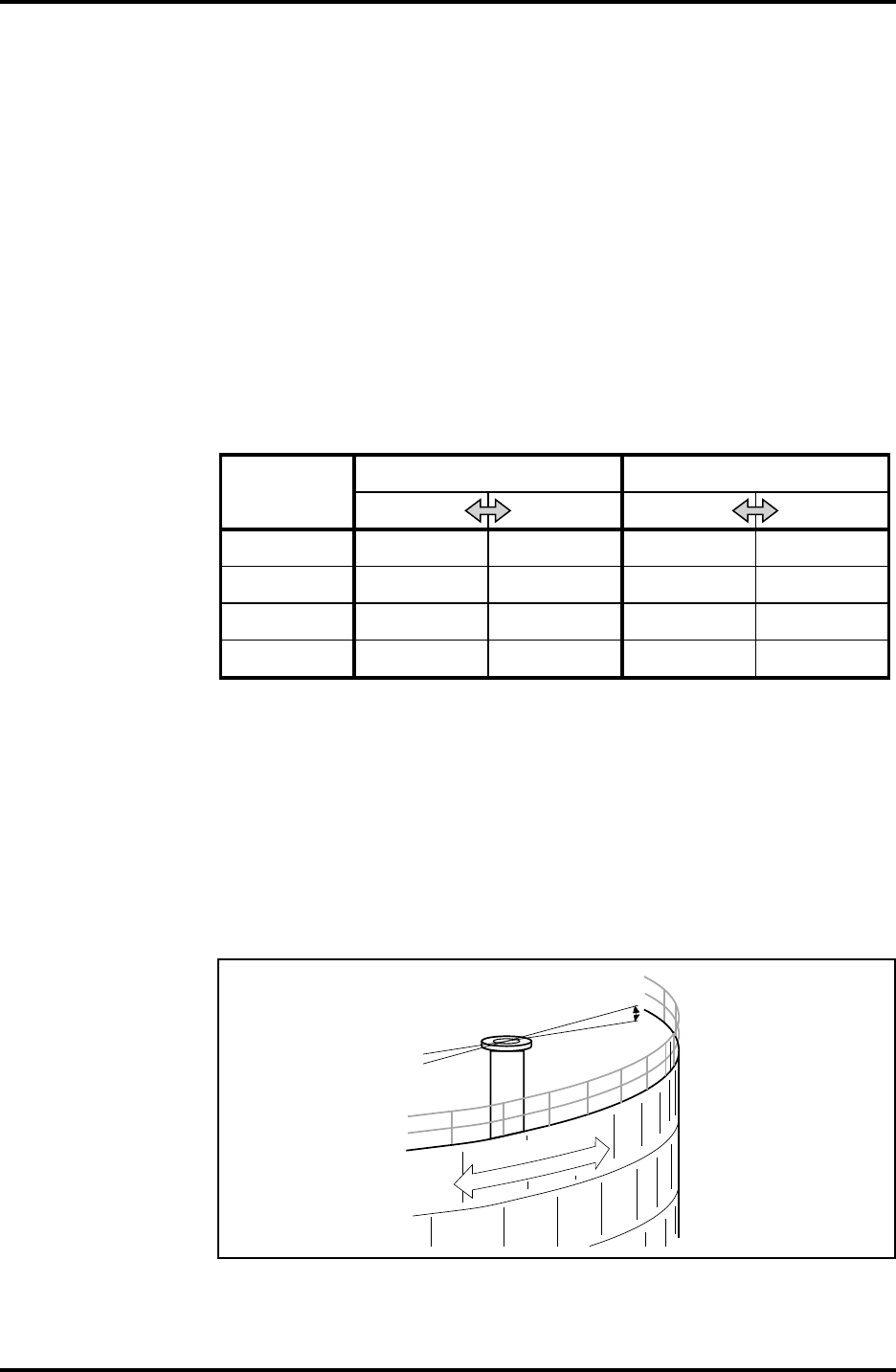
10.2.1 Inclination of the Parabolic Antenna Gauge
The radar beam should be directed 1.5° towards the tank center.
Generally an Inclination Device must be used to ensure the correct
angle of the gauge. However, for products with high condensa-
tion, like bitumen/asphalt applications, the radar beam should be
directed vertically without any inclination towards the tank cen-
ter.
When the Inclination Device is used the plane of the cover is al-
lowed to lean a maximum of 5.5° away from the tank wall and a
maximum of 2.5° towards the tank wall. It must also be horizontal
within ± 4° along the tank wall. See figure 10.3.
If the plane of the cover has an inclination of 1°-2° away from the
tank wall and is horizontal within 1° along the wall then the Para-
bolic Antenna Gauge can be directly mounted on the cover with-
out the use of the Inclination Device. See figure 10.3.
Figure 10.3 shows the requirements on the flange for RTG 2930 with and without the Inclina-
tion Device.
± 4 ° MAX
HORIZONTAL
2.5° MAX
TANK WALL
HORIZONTAL
5.5° MAX
With Inclination Device
TANK WALL
HORIZONTAL
1 ° - 2 °
±1° MAX
Without Inclination Device
Saab TankRadar L/2
35
US Version. Seventh edition, June 1995
Installation Manual
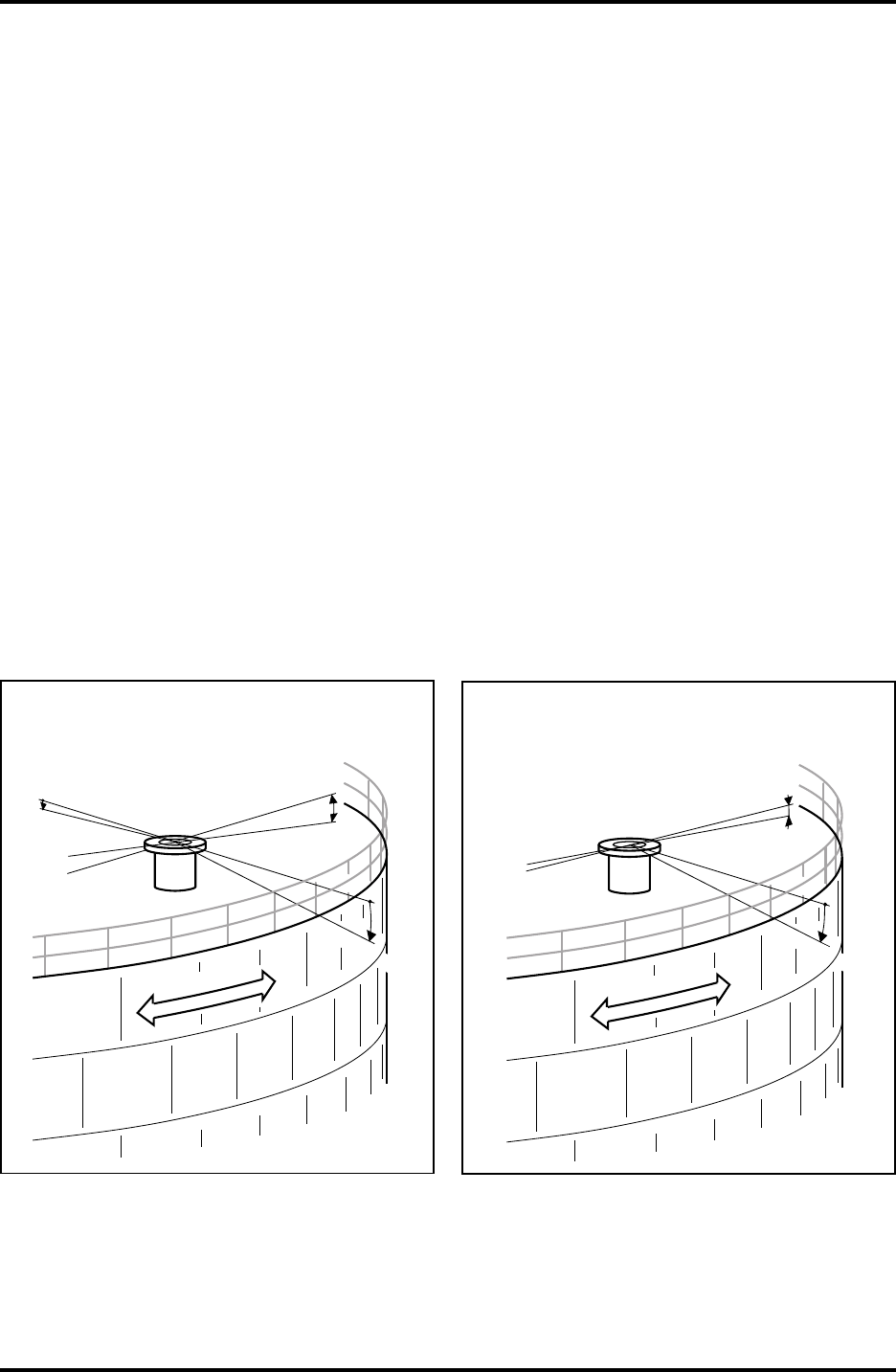
10.2.2 Free Space Requirement
The radar beam of the Parabolic Antenna Gauge is 10° wide. Ob-
stacles (construction bars, pipes larger than Ø 2", etc.) within the
radar beam are generally not accepted, as these can give a disturb-
ing echo, see figure 10.11. However, in most cases, a smooth tank
wall or heating coils can be accepted in the radar beam, since the
interference from these can be regarded as small. For evaluation
contact Saab Tank Control.
Vertical
plumb line
Free
passage
5°
Antenna
axis
1.5°
5°
Figure 10.2 shows the free space requirements for RTG 2930.
36
Saab TankRadar L/2
US Version. Seventh edition, June 1995
Installation Manual
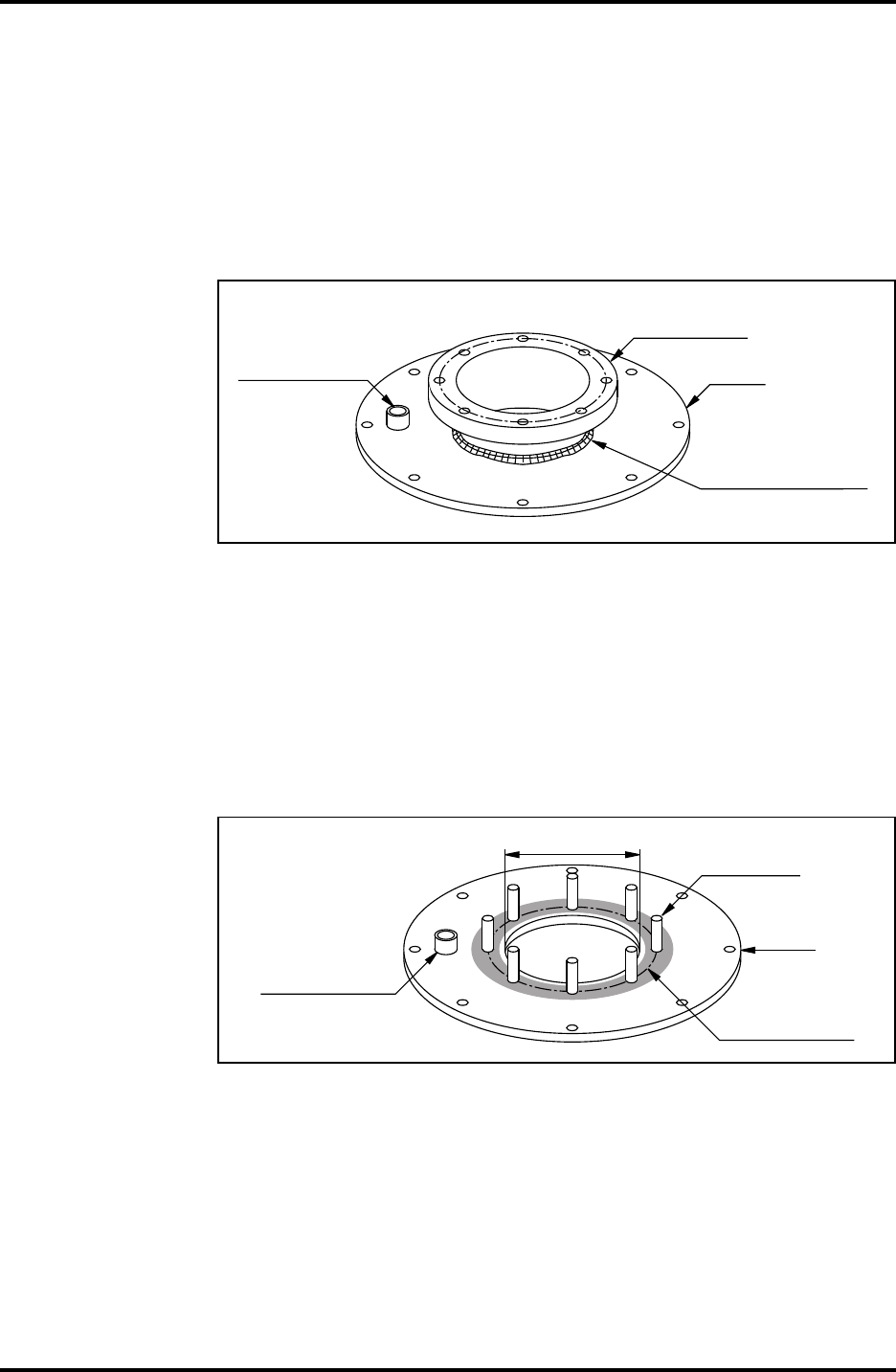
10.2.3 Flange Requirements
The Parabolic Antenna Gauge can mounted on a welding neck
flange that is welded to the cover or fixed to the cover with eight
M16-stud screws welded onto the cover.
The dimensions of the welding neck flange are stated on the in-
stallation drawing for RTG 2930, see list of drawings in chapter 13.
See figure 10.5.
Ullage plug
for hand dipping.
Welding Neck
Flange
Cover
Hole Ø 145 mm must
be made for Welding
Neck Flange
Figure 10.5 shows a welding neck flange for RTG 2930.
If the Parabolic Antenna Gauge is mounted with stud screws
directly onto the cover then the surface for the gasket must be
smooth in order to provide a good sealing. See figure 10.6. The top
of the cover must have a 145 mm diameter hole through which the
antenna is mounted. It must be possible to remove the cover when
installing the antenna. Refer to installation drawing for manufac-
turing of cover, see list of drawings in chapter 13.
Ø 145 mm M16 (8X)
Sealing surface
must be smooth.
Ullage plug
for hand dipping.
Cover
Figure 10.6. The gauge can be mounted on a manhole cover.
10.2.4 New Tanks
At new installations the distances from the tank wall to the an-
tenna axis should be 0.8 m or larger.
Saab TankRadar L/2
37
US Version. Seventh edition, June 1995
Installation Manual
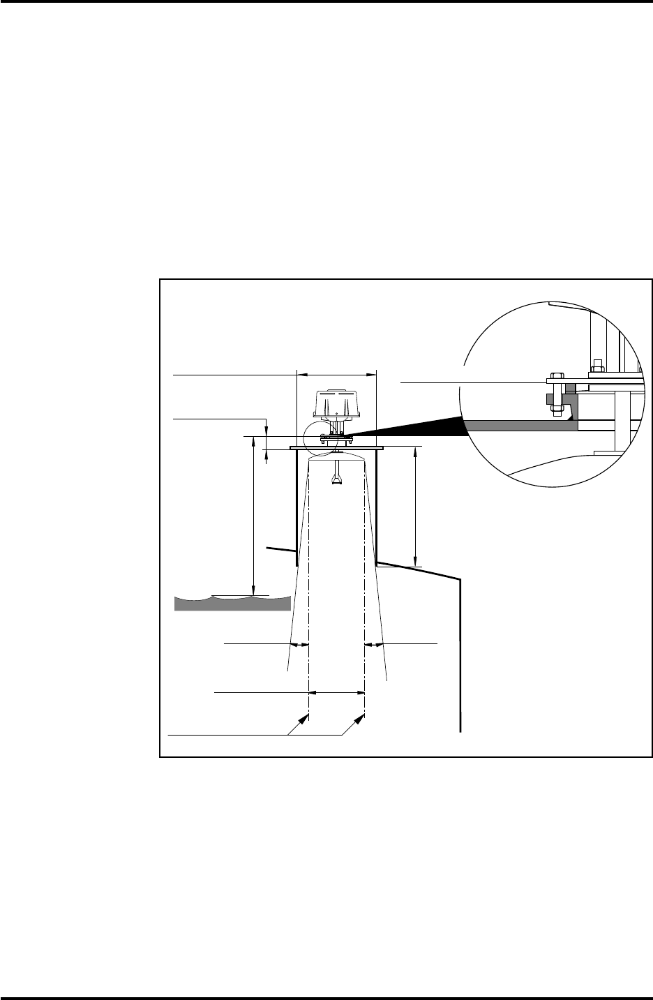
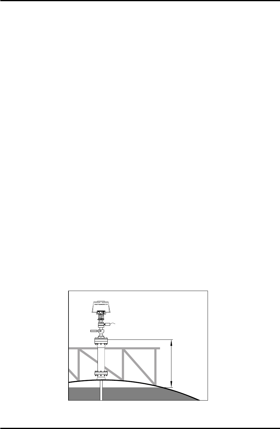
10.2.5 Socket Requirements
When using a Ø 20" socket the height of the socket must not ex-
ceed 0.6 m.
If a socket with a larger diameter is used then the height can also
be larger. In this case there must be a free passage for the radar
beam within a 5° angle from the edge of the Parabolic Reflector to
the bottom end of the socket. See figure 10.7.
Note: The distance from the top of the customer’s flange to the maximum
product surface should not be less than 1.0 m. The highest accuracy
cannot be maintained at distances less than 1.0 m.
5° Min
5° Min
Vertical
Plumb Line
Ø 455 mm
Larger than
Ø 20"
Socket
height
max
0.6 m
Min 1.0 m
to product
surface
Max
100 mm
Bottom of flange
Figure 10.7 shows the requirements on the socket to RTG 2930.
38
Saab TankRadar L/2
US Version. Seventh edition, June 1995
Installation Manual
10.3 Requirements for the Still Pipe Gauge, RTG 2940
Please refer also to the mechanical installation drawing for more
information on the installation requirements.
10.3.1 Still Pipe Requirements
The Still Pipe Gauge fits 6", 8", 10" and 12" flanges and pipes. This
adaption is accomplished by selecting a suitable Transition Cone.
The gauge has a meeting flange for sealing of the tank.
Note: The gap between the Transition Cone and the still pipe must not be
larger than 4 mm anywhere along the lower end of the Transition Cone.
Table 10.1 shows the wide range of schedules and pipe inner
diameters that the Transition Cones can be mounted in.
The still pipe must be vertical within 0.3° (0.1 m over 20 m).
SCH 20 S SCH 40 S
SCH 20 S
SCH 20 S
SCH 20 S
SCH 80 S
SCH 40 S
SCH 40 S
8"
10"
12"
6"
Main Pipe
Diameter
Pipe Schedule Pipe Inner Diameter
From From (mm)To To (mm)
Ø 156.3 Ø 154.1
Ø 206.3
Ø 260.3
Ø 311.1
Ø 193,7
Ø 254.5
Ø 304.9
Tables 10.1 shows the pipe schedules and the maximum area of the holes.
Note: If the Still Pipe Gauge has to be mounted on a pipe with a schedule
or an inner diameter that is not included in the table above, then please
contact Saab Tank Control or the Saab Tank Control representative.
10.3.2 Flange Requirements
The Still Pipe Gauge fits flanges of sizes 6", 8", 10" and 12". The
gauge has a meeting flange for sealing of the tank. The flange
must be horizontal within ±2°.
±2° MAX
TANK WALL
Figure 10.8. The flange must be horizontal within
±
2
°
.

Saab TankRadar L/2
39
US Version. Seventh edition, June 1995
Installation Manual
10.3.3 New Tanks
When constructing new tanks, an 8" still pipe or larger is recom-
mended. This is especially relevant in tanks with sticky, viscous
products. Before manufacturing a new still pipe, we recommend
that you contact the Project Department at Saab Tank Control for
advice. See also drawing with recommendations for still pipe
dimensions, see list of drawings in chapter 13.
For highest performance, the total area of the slots or holes in the
still pipe must not exceed the values shown in table 10.2 below.
The area in the table is the total area of the holes over the entire
length of the pipe, regardless of its length. In some cases it is pos-
sible to allow a larger area of the holes in the still pipe, than the
area stated in table 10.2. When the limits are exceeded, please
contact Saab Tank Control for advice.
Tables 10.2 shows the maximum area of the slots or holes.
Pipe Dimension 6" 8" 10" 12"
Max Area of
Slots or Holes 0.03 m 0.12 m 0.40 m 1.00 m
2222
10.3.3 Service Space
See installation drawing for requirements on the service space. It is
necessary to have this free space when installing the gauge, when
doing service on it and when hand dipping or taking samples. The
height of the free space requirement depends on which Transition
Cone that is used. The larger Transition Cones require higher free
space.

40
Saab TankRadar L/2
US Version. Seventh edition, June 1995
Installation Manual
10.4 Requirements for the LPG/LNG Gauge, RTG 2960
The LPG/LNG Gauge fits to a 6" flange and requires a still pipe
for measurement.
Please refer to the mechanical installation drawing for more de-
tailed information of the requirements on the installation of the
LPG/LNG Gauge.
10.4.1 Temperature and Pressure Measurement
A prerequisite for high accuracy level-measurement is that tem-
perature and pressure measurements are made. This can be ac-
complished in some different ways.
• An Independent DAU can interface both pressure sensors
and temperature sensors.
• A Current Loop Card in the Transmitter Head to connect the
pressure sensor and a Slave Data Acquisition Unit for the
temperature measurement.
10.4.2 Still Pipe
A still pipe must be installed before the gauge is installed. The still
pipe is customer supplied and should be manufactured according
to the drawings specified in chapter 13.
Either a steel pipe with an inner diameter of 100 mm and 2-3 mm
wall thickness or a 4" SCH 10 stainless steel pipe can be used.
Specify the type of pipe in the Required System Information Form.
The still pipe must be vertical to within ±0.5°. The customer flange
must be horizontal within ±1°.
10.4.3 References in Still Pipe
The still pipe is made with a number of holes along the length of
it. Some of these holes are used to mount the Reference Pins and
the Reflector Plug (if included).
The Reflector Plug is used for calibration of the gauge. The Refer-
ence Pins provide verification of the measurement when the tank
is pressurized. The other holes provide pressure equalization so
that the level is the same on the inside as on the outside of the
pipe. These holes can be chosen to 20 mm or 3/4". All holes must
be placed along a line on one side of the pipe. The direction of the
line, along which the lines are located, must be marked clearly on
the tank flange and customer flange.
There are two systems for references in the still pipe:
- One Reference Pin at the top of the still pipe and a Reflector
Plug at the bottom of the pipe.
- Two or three reference pins installed at the top, the bottom
and the middle of the pipe. This system is used when it is not
possible to have an epoxy Reflector Plug in the tank.
Saab TankRadar L/2
41
US Version. Seventh edition, June 1995
Installation Manual
10.4.4 System with Reference Pin and Reflector Plug
At the top of the pipe there is a reference pin and at the bottom
there is a reference plug made from epoxy resin.
Note: If the products that will be stored in the tank are not compatible
with epoxy resin, the system with two or three Reference Pins should be
used instead, see chapter 10.4.5.
See installation drawings for information on where to place the
references in the still pipe. Enclosed with reference pin and bottom
plug are instructions on how to install these.
10.4.5 System with Reference Pins Only
Saab Tank Control delivers three Reference Pins to each Radar
Tank Gauge and they have to be mounted in the still pipe before it
is lowered into the tank. For more information please refer to the
installation drawings, see List of Drawings in chapter 8.
Position the holes for the Reference Pins so that the top pin is
located at approximately 95% of the total tank height but at least
0.8 m below the flange of the still pipe. Place the second pin at
approximately 50% level.
Place the lowest pin at approximately 20 % of the tank height but
at least 0.8 m above the lower end of the pipe.
On tanks with tank heights of less than 7 m, only the top and
bottom reference pins are used.
10.4.6 Extension Pipe for Minimum Distance
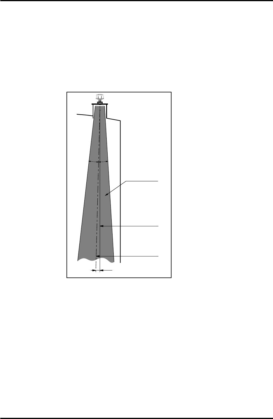
The Radar Tank Gauge should be placed so that there is always
800 mm or more between the Closing and the maximum product
level. If the tank is filled completely, an extension pipe can be
mounted to raise the Radar Tank Gauge so that it measures cor-
rectly all the way up to the maximum level. See figure 10.9.
W11W12
FOR
INTRINSICALLY
SAFE CIRCUITS
ONLY
"i"
Min 800
mm to
product
surface
Figure 10.9 shows an extension pipe.
42
Saab TankRadar L/2
US Version. Seventh edition, June 1995
Installation Manual
W11W12
FOR
INTRINSICALLY
SAFE CIRCUITS
ONLY
"i"
Waveguide Unit
Transmitter
Head
M6 stop
screw
4. Carefully enter the Horn and Flange
Assembly into the nozzle. Tighten
the flange onto the customer’s flange
using customer supplied screws and
nuts.
Check that the socket height is less
than 330 mm.
Cone and flange
assembly
Customer's
flange
Customer's
gasket
Spring
Sleeve
1. Check that all parts and tools are
available before carrying them up to
the tank top.
2. Mount the Spring Sleeve into the
baser of the Transmitter Head. Turn
the Spring Sleeve so that it fits into
one of the notches.
3. Mount the Waveguide Unit into the
base of the Transmitter Head. On one
end of the Waveguide Unit there are
two screws with washers fitted.
Mount the Waveguide Unit with this
end first into the base of the Trans-
mitter Head. Enter the stop screws
and tighten them.
11 Mechanical Installation of the Radar Tank Gauges
Please refer also to the mechanical installation drawings for more
information. A list of the drawings is presented in chapter 13.
11.1 Installation of Horn Antenna Gauge, RTG 2920
Note: When determining the dimensions for conduits (if used), make
note that the Horn Antenna Gauge may be inclined 4
°
towards the center
of the tank. See figure 11.7. Use flexible conduits close to the Radar Tank
Gauge.
Follow this step by step instruction when installing the Cone
Antenna Gauge, RTG 2920
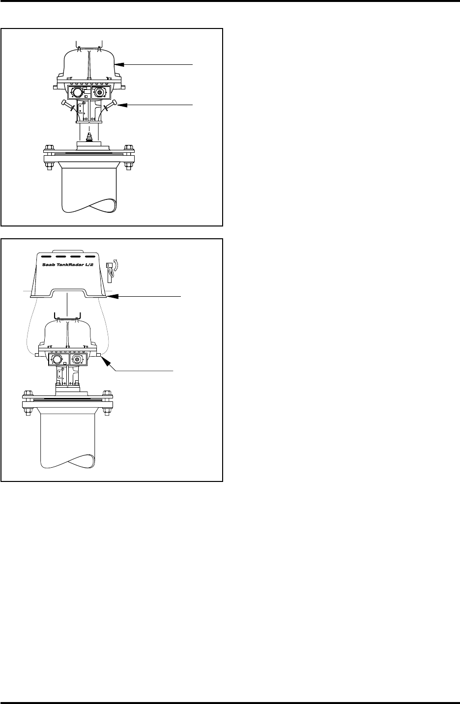
Saab TankRadar L/2
43
US Version. Seventh edition, June 1995
Installation Manual
5. Mount the Transmitter Head onto
the flange. Fit and tighten the four
M10 screws with washers.
6. Mount the Weather Protection Hood
and secure with locking pins.
W11W12
FOR
INTRINSICALLY
SAFE CIRCUITS
ONLY
"i"
Transmitter
Head
Four screws
and washers
Mount Weather
Protection Hood
and secure with
locking pins
Mounting
pins
W11W12
FOR
INTRINSICALLY
SAFE CIRCUITS
ONLY
"i"
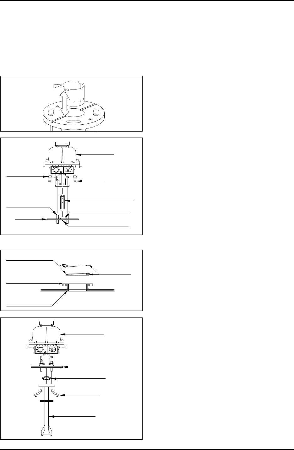
44
Saab TankRadar L/2
US Version. Seventh edition, June 1995
Installation Manual
11.2 Installation of the Parabolic Antenna Gauge, RTG 2930
Follow this step by step instruction when installing the Parabolic
Antenna Gauge.
1. Check that all parts and tools are available before carrying
them up to the tank top.
Customer
manhole cover
Inclination
Device
Welding neck
flange
(customer supply)
Gaskets
W11W12
FOR
INTRINSICALLY
SAFE CIRCUITS
ONLY
"i"
Closing
Transmitter
Head
Antenna
feeder
Four M10
nuts
Two O-rings
3. Mount the Waveguide Unit into the
base of the Transmitter Head. On one
end of the Waveguide Unit there are
two screws with washers fitted.
Mount the Waveguide Unit with this
end first into the base of the Trans-
mitter Head. Enter the stop screws
and tighten them.
On the Closing there are two guide
pins on one sided and only one on
the other. Fit the Transmitter Head to
the side of the Closing that has two
guide pins with four M10 nuts and
washers. These parts can be
preassembled at a more convenient
location than the tank top.
4. If the Inclination Device is used then
check that the gaskets are correctly
applied on the Angular Rings.
Mount the Angular Rings onto the
flange or manhole cover.
5. Check that the two O-rings are
placed in their separate grooves on
the top surface of the Antenna
Feeder. Mount the Antenna Feeder to
the Closing, entering the guide pin
into its corresponding hole. Fit the
four nuts and tighten.
Spring
Sleeve
2. Mount the Spring Sleeve into the
baser of the Transmitter Head. Turn
the Spring Sleeve so that it fits into
one of the notches.
W11W12
FOR
INTRINSICALLY
SAFE CIRCUITS
ONLY
"i"
Waveguide Unit
Transmitter
Head
M6 stop
screw
Closing
Four M10
nuts and
washers
Four M10
stud screws Two guide pins
One guide pin
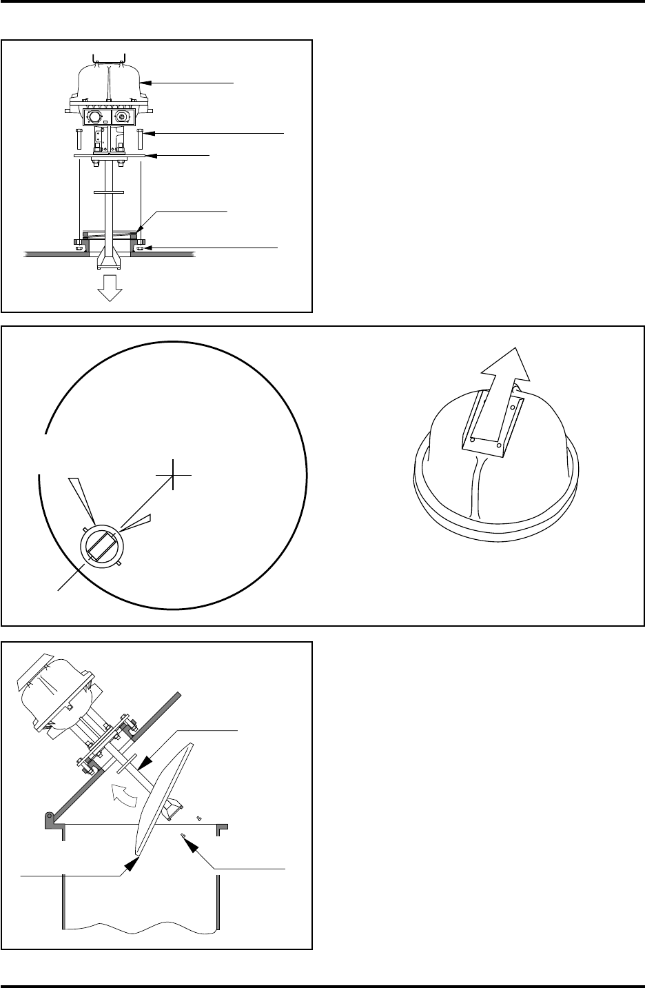
Saab TankRadar L/2
45
US Version. Seventh edition, June 1995
Installation Manual
6. Carefully mount the Transmitter
Head with the Closing and Antenna
Feeder onto the flange and direct the
Transmitter Head so that one of the
ridges which are cast into the Safety
Enclosure is pointed to the tank
center.
Fit eight M16 or 3/4" screws and
tighten them by hand. These screws
are customer supplied.
Closing
Inclination
Device
M16 or 3/4" screws
(customer supply)
M16 or 3/4" nuts
(customer supply)
W11W12
FOR
INTRINSICALLY
SAFE CIRCUITS
ONLY
"i"
Transmitter
Head
Tank center
Tank
Ridges
Transmitter
Head
Direct ridges on
Transmitter
Head toward
tank center
within ±2°
Antenna
feeder
Three M6
screws
Parabolic
reflector
7. Open the manhole cover. Fit the
Parabolic Reflector onto the Antenna
Feeder. Fit and tighten the three
screws.
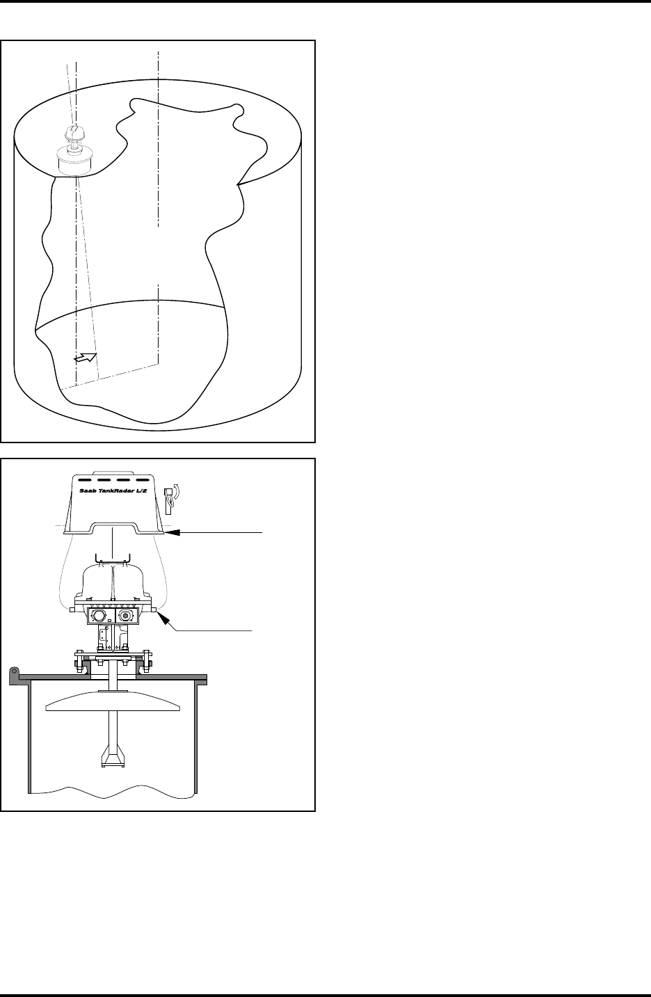
46
Saab TankRadar L/2
US Version. Seventh edition, June 1995
Installation Manual
8. Replace the manhole cover. Adjust
the inclination of the Gauge, so that
the antenna axis points 1.5° to the
tank center, using the Inclination
Device. Tighten the eight screws for
the Closing.
Note: For bitumen tanks, the gauge
should be mounted with 0
°
inclination.
Tank center
Plumb line
Incline 1.5°
towards
tank center
Mount Weather
Protection Hood
and secure with
locking pins
Mounting
pins
W11W12
FOR
INTRINSICALLY
SAFE CIRCUITS
ONLY
"i"
9. Fit the Weather Protection Hood onto
the two pins of the Transmitter
Head.
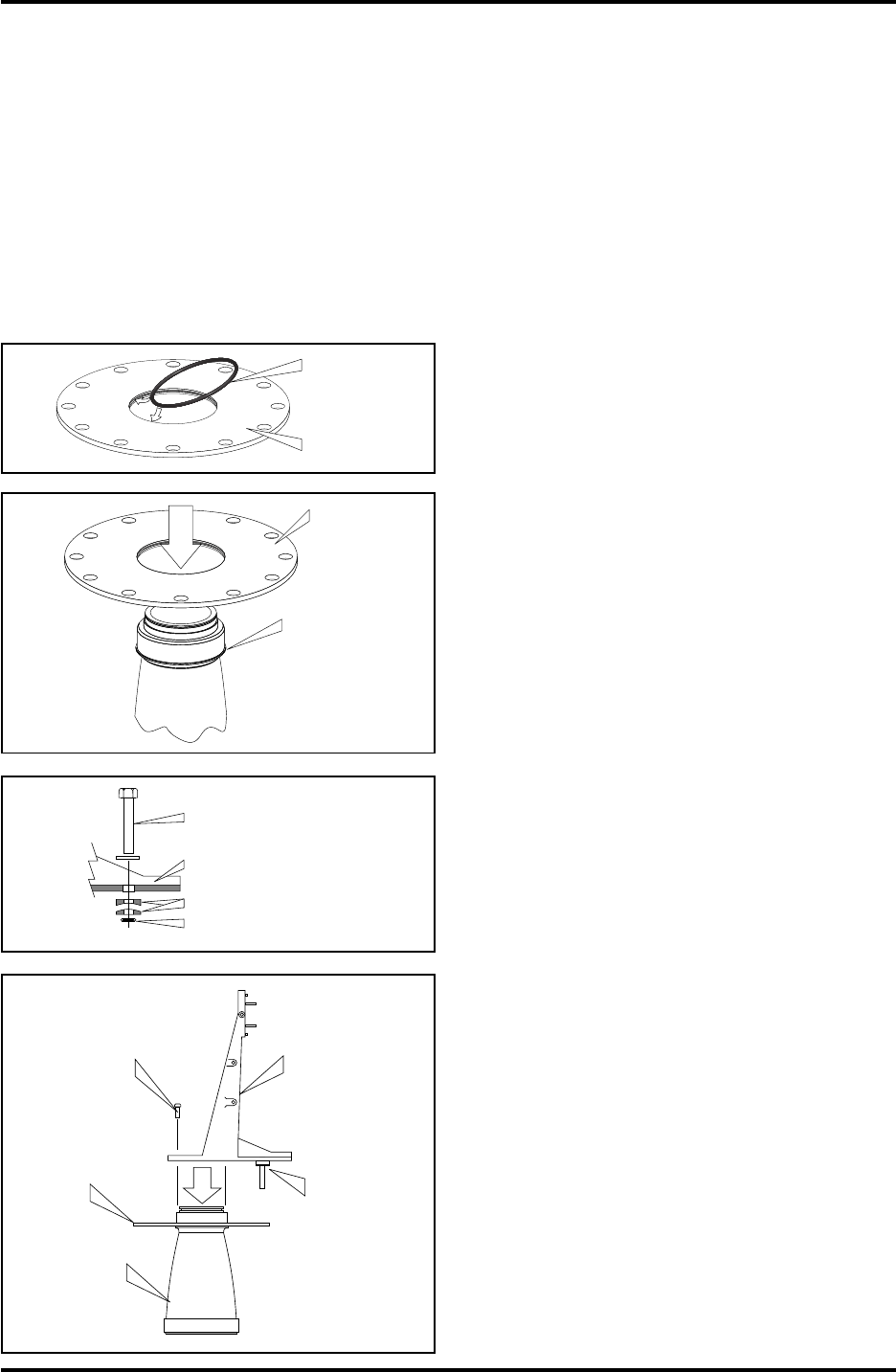
Saab TankRadar L/2
47
US Version. Seventh edition, June 1995
Installation Manual
11.3 Installation of the Still Pipe Gauge, RTG 2940
Note: If there is no flange on the still pipe a clamp flange must be
mounted.
Follow this step by step instruction when installing the Still Pipe
Gauge.
1. Check that all parts and tools are available before carrying
them up to the tank top.
2. Enter the Cone into the still pipe to make sure it fits. Maxi-
mum gap between the Cone and the pipe is 4 mm.
Flange
O-Ring
Cone
Flange
M16 screw and
washer
Spherical washers
O-Ring
Stand
Four screws
Flange
Cone
Stand
M16-screw
with
spherical
washers
3. Mount the O-ring into the flange.
4. Press the Flange onto the Cone. Use
manual force only. If there is much
resistance, try putting some grease
on the O-ring.
5. Place the M16 screw with a washer
in the Stand. Fit the spherical wash-
ers onto the screw and secure these
washers by mounting the small O-
ring under the washers. This O-ring
can be left on when the Stand is
mounted onto the flange.
6. Mount the Stand onto the Cone and
tighten the four screws.

48
Saab TankRadar L/2
US Version. Seventh edition, June 1995
Installation Manual
7. Place a customer supplied gasket on
the flange of the still pipe.
8. Mount the assembly into the still
pipe. Use only manual force. Too
much force can damage the Cone.
Mount customer supplied screws
and nuts and tighten. Make sure the
Cone is centered in the still pipe. Fit
the M16-nut and tighten.
M16 nut
and
washer
Flange
Cone
Stand
Still pipe
Customer´s
gasket
O-Ring
Waveguide
Unit
Transmitter Head
Four M10 nuts
and washers
Transmitter
Head
Stand
Cables
pointing
down
Note:
Guide
pins
10. Slide the Waveguide Unit into the
Transmitter Head. It can only be
entered in one way.
11. Mount the Transmitter Head onto
the Stand with its cable connections
pointing down. Be careful not to
drop the Waveguide Unit as it is not
in i fixed position. Check that the
guide pins on the Stand enter the
holes on the base of the Transmitter
Head properly. Fit and tighten the
M10 nuts.
12. The Waveguide Unit will not be in a
fixed position until the Transmitter
Head has been tightened to the
Stand.
Spring
Sleeve
9. Mount the Spring Sleeve into the
baser of the Transmitter Head. Turn
the Spring Sleeve so that it fits into
one of the notches.
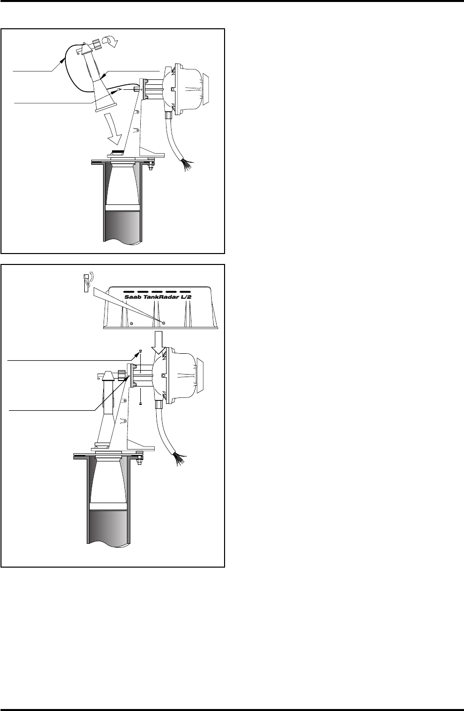
Saab TankRadar L/2
49
US Version. Seventh edition, June 1995
Installation Manual
13. Fit the Waveguide Connection into
the Cone. It must be firmly pressed
down so that there is a well defined
snap as the lower end fits onto the
O-ring of the Cone. Tighten the nut
onto the thread of the Waveguide
Unit by hand.
Mount the ground wire onto the
Stand.
Waveguide
Connection
Braided
ground
wire
Note:
Press until a
well defined
snap.
Tighten by hand
Self tapping
screw
2 x M6 Stop
screws
Note: Tighten top
screw first
Mount Weather
Protection Hood
and secure with
locking pins
Fit the two
mounting pins
for the Weather
Protection Hood
14. Secure the Waveguide Unit by tight-
ening two stop screws into the base
of the Transmitter Head. Tighten the
top screw first. Fit the two mounting
pins onto the Stand and mount the
Weather Protection Hood onto the
four pins.
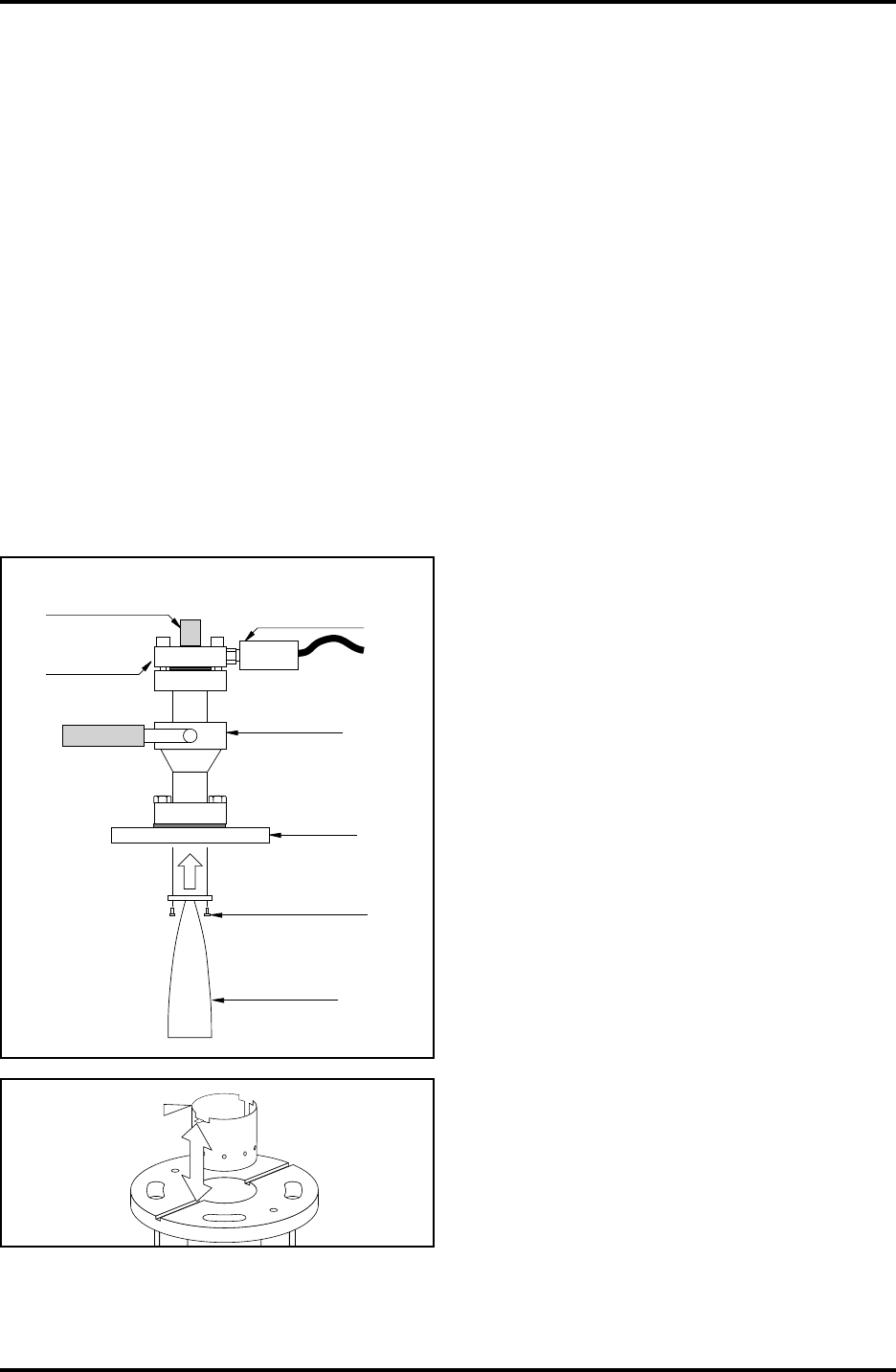
50
Saab TankRadar L/2
US Version. Seventh edition, June 1995
Installation Manual
11.4 Installation of the LPG/LNG Gauge, RTG 2960
Follow this step by step instruction when installing the LPG/LNG
Gauge.
Note: There must be a clear mark on the customer flange to show the
direction of the reference pins in the still pipe. Carefully check that the
Closing is mounted in the appropriate angle relative to that mark.
See also the installation drawings. See chapter 13 for list of draw-
ings.
The Lower Flange, the ball valve and the Closing are
preassembled and delivered as one unit.
1. Check that all parts and tools are available before carrying
them to the tank top.
2. Install the still pipe according to mechanical installation
drawing 9150057-986 or 9150057-987.
3. Enter the Cone into the still pipe to make sure it fits. Maxi-
mum gap between the Cone and the pipe is 2 mm.
4. Mount the Pipe Cone onto the Clos-
ing using four M6 Allen head screws.
Be careful when handling the Clos-
ing with the Pipe Cone mounted
onto it as it is very important that the
Pipe Cone is not deformed.
Do not remove the yellow protective
cap.
Pressure
transducer
Lower
Flange
Ball
Valve
Four M6
screws
Closing
Pipe
Cone
Do not remove
this protective cap
Spring
Sleeve
5. Mount the Spring Sleeve into the
baser of the Transmitter Head. Turn
the Spring Sleeve so that it fits into
one of the notches.
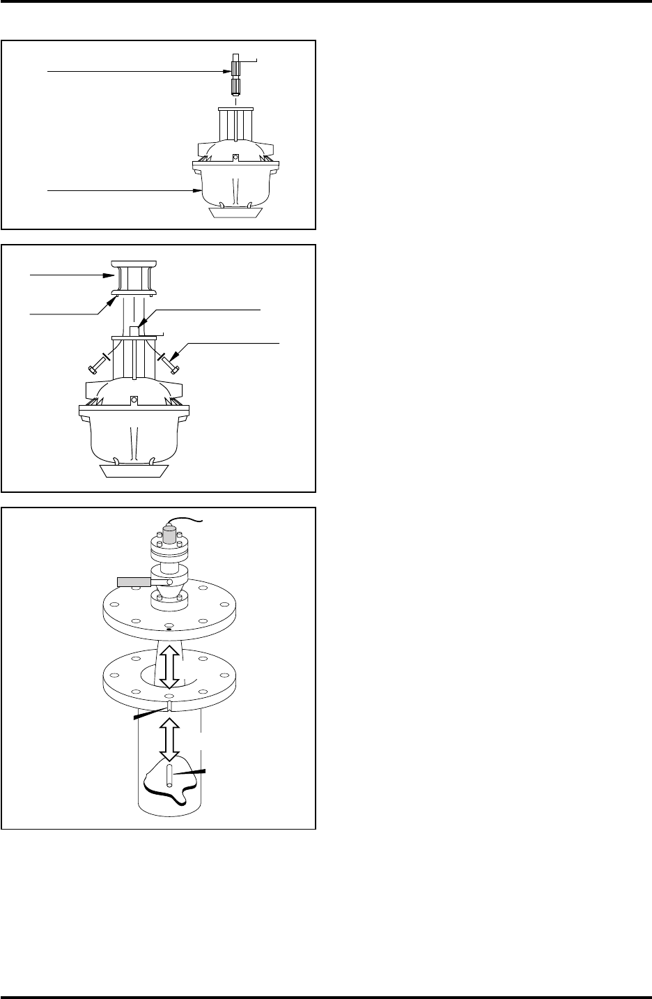
Saab TankRadar L/2
51
US Version. Seventh edition, June 1995
Installation Manual
6. Put the Transmitter Head upside
down on a flat surface and fit the
Waveguide Unit into the base.
Waveguide Unit
Transmitter Head
7. Fit the Housing to the Transmitter
Head. Carefully check that the Guide
Pins enter their respective holes and
turn the lever of the Waveguide Unit
so that it fits into the corresponding
recess in the Housing. Tighten the
Housing to the base of the Transmit-
ter Head using four M10 screws and
washers.
Housing
Guide pins
Waveguide
Unit
4 M10 screws
and washers
8. Place customer supplied gasket on
customer's flange. Carefully fit the
Pipe Cone into the still pipe and
tighten the Closing onto the 6" flange
using customer supplied screws and
nuts. Direct the Closing so that the
marking hole aligns with the notch
or mark on the customer flange.
9. The tank is now sealed and can, as
far as Saab Tank Control equipment
is concerned, be pressurized.
Customer
Flange
Reference
Pin
Align!
Align!
Notch indicating
the direction of
the Reference
Pins
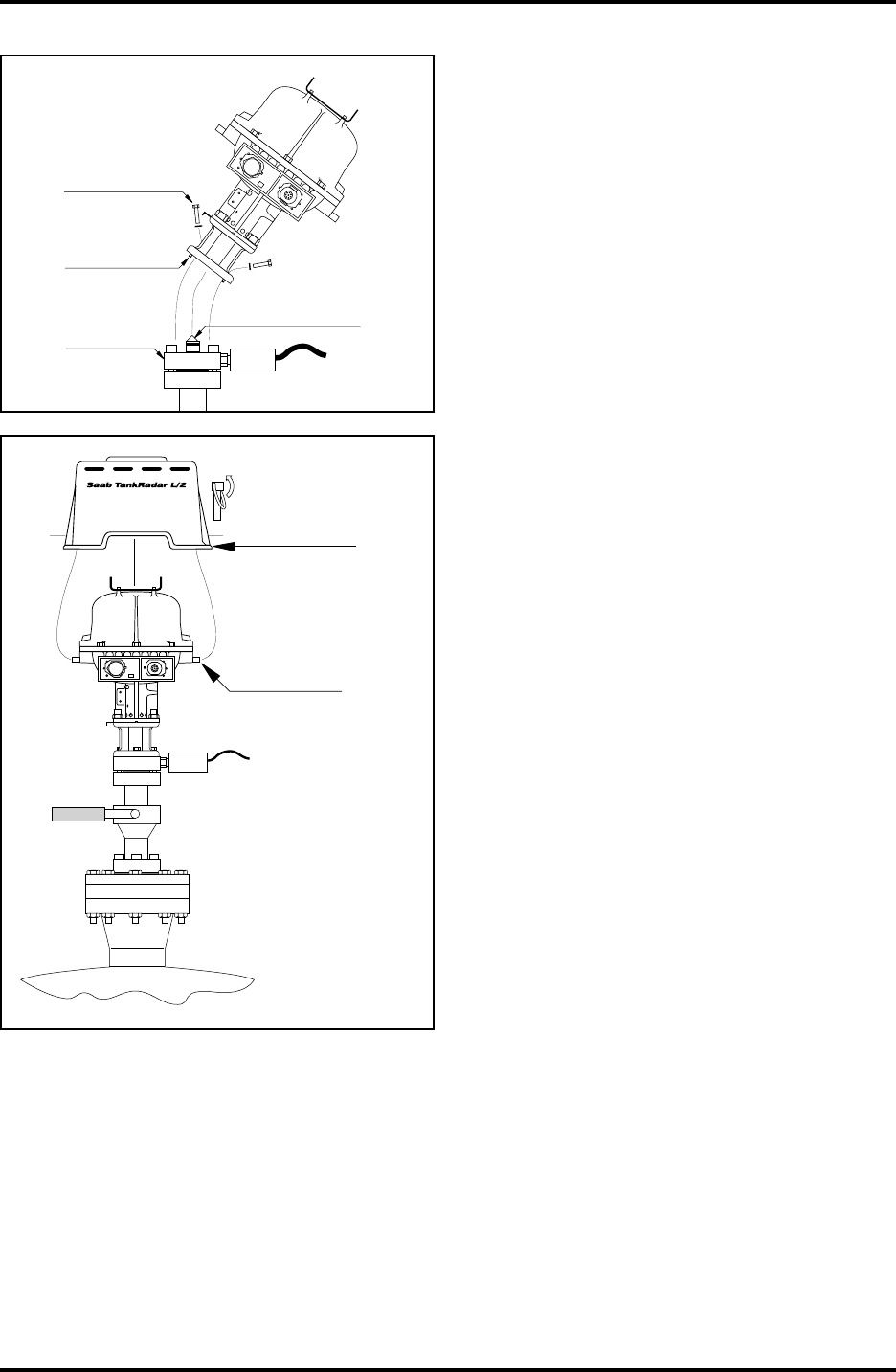
52
Saab TankRadar L/2
US Version. Seventh edition, June 1995
Installation Manual
10. Remove the yellow protection cap,
but do not remove the rubber cone.
Fit the Transmitter Head and the
Housing onto the Lower Flange.
Carefully check that the Guide Pins
enter their respective holes. Tighten
using four M10 screws and washers.
Guide pins
Lower
Flange
4 M10 screws
and washers
W11W12
FOR
INTRINSICALLY
SAFE CIRCUITS
ONLY
"i"
Do not
remove
this cone!
11. Fit the Weather Protection Hood onto
the mounting pins of the Transmitter
Head.
Mount Weather
Protection Hood
and secure with
locking pins
Mounting
pins
W11W12
FOR
INTRINSICALLY
SAFE CIRCUITS
ONLY
"i"

Saab TankRadar L/2
53
US Version. Seventh edition, June 1995
Installation Manual
12 Electrical Installation
Warning! Isolate and terminate ends of unused wires. The intrinsic
safety may be jeopardized if any cable ends are hanging loose. Use certi-
fied battery operated instruments only. Use Saab Tank Control original
spare parts only.
Note: For all electrical installation, please see the instructions in the
electrical installation drawings. See list of drawings in chapter 13.
12.1 Cabling for Power Supply
The cables used for the power supply connection must be suitable
for the supply voltage in question and also approved for use in
hazardous area where it is applicable. In the USA, for example,
explosion proof conduits must be used in the vicinity of the tank.
The wire areas must be selected not to cause too much voltage
drop on the way to the RTGs, the DAUs, the FCUs, etc.
Each Radar Tank Gauge and Field Communication Unit have a
switch for voltage selection that can be set to either 115 VAC or 230
VAC. Check that the switch is set in the right position before
power is connected. See chapter 3.1.3 and 6.3.
The selection of 115 or 230 VAC power supply for the Independent
Data Acquisition Unit is made by connecting a strap on one of the
printed circuit boards in the flameproof enclosure. See chapter
4.7.1. Maximum power consumption is 10 W.
The Slave Data Acquisition Unit receives its power via the local
line from the associated Radar Tank Gauge.
The power supply connection to the Radar Tank Gauge should be
made with wires according to table 12.1 below. The table shows
the voltage drop at various cable lengths and wire areas at the
maximum power consumption of 80 W. The figures shaded in
grey indicate combinations of lengths and areas that might result
in too high voltage drops.
1.5 mm
(AWG 16 or
similar)
0.75 mm
(AWG 18 or
similar)
1.5 mm
(AWG 16 or
similar)
115 V 230 V
Cable Length 0.75 mm
(AWG 18 or
similar)
100 m 330 ft. 3.1 V 1.6 V 1.6 V 0.8 V
200 m 660 ft. 3.2 V 3.2 V 1.6 V
500 m 1640 ft. 4 V
22 22
6.3 V
16 V 8 V 8 V
Table 12.1. Grey areas show too high voltage drop.

54
Saab TankRadar L/2
US Version. Seventh edition, June 1995
Installation Manual
12.2 Cabling for TRL/2 Bus
The TRL/2 bus requires a twisted and shielded pair with an area
of min 0.50 mm2 (AWG 20 or similar). The maximum length of the
TRL/2 bus is 4 km. The TRL/2 Field Bus can normally use exist-
ing cables in the tank area.
Note: Wherever two TRL/2 Buses run alongside each other, sharing the
same cable or conduit tube, individual shielding is mandatory in order to
avoid crosstalk.
12.3 Grounding
According to national code of practice the Transmitter Head or
Data Acquisition Unit can be grounded by connecting an exterior
4 mm2 wire to a potential equalization network, or, if no such
exists, to the tank structure. A grounding lug is available on the
enclosure for this purpose.
Note: When the enclosure is connected to a potential equalizing network
or to the tank structure, the protective ground with the power supply
must not be connected.
If the enclosure is not externally grounded, the protective ground with
the power supply should be connected.
12.4 Electrical Installation of the Radar Tank Gauge, RTG
12.4.1 The Non-Intrinsically Safe Connection (W11)
The power connection is made with two wires. The TRL/2 Field
Bus connection is made with a single pair of shielded twisted
wires.
A Junction Box is required for the non-intrinsically safe connection
of the power supply and the TRL/2 Field Bus. The junction box
can either be customer supplied or supplied by Saab Tank Control
as an option, see chapter 7. The three wires in the cable output that
are not used must be properly insulated and terminated in the
junction box.
12.4.2 The Intrinsically Safe Connection (W12)
See chapter 3.1.2 for information on number of cables in lead seal.
If the distance between the Transmitter Head and the Slave Data
Acquisition Unit is longer than 2.0 m, a junction box must be used
to connect an extension cable. This extension cable must not be
longer than 50 m. For safety reasons the ends of the unused wires
must be properly insulated and terminated. The junction box can
either be customer supplied or supplied by Saab Tank Control as
an option, see chapter 7.
A flexible protective hose for the wires is delivered with the Bar-
rier Unit or the Current Loop Card, or with the Transmitter Head
if the units have been factory installed. For reasons of electromag-

Saab TankRadar L/2
55
US Version. Seventh edition, June 1995
Installation Manual
netic interference and compatibility it is very important that a
continuous metal shield is covering the wires between the Trans-
mitter Head and the Slave Data Acquisition Unit. If an extension
cable is used, both the cable and the junction box must provide
good shielding.
12.5 Electrical Installation of the Data Acquisition Unit, DAU
Instructions for the connection of the Data Acquisition Unit is
given on the inside of its cover.
12.5.1 Electrical Installation of the Slave DAU, DAU 2100
The connection to the Radar Tank Gauge is done according to the
instructions in chapter 12.4.2 above.
Either Pt 100 (spot element) or Cu 100 (averaging sensor) tempera-
ture sensors can be used. If the sensors are connected with com-
mon return wires then jumpers must be connected in the Data
Acquisition Unit terminals.
Intrinsically safe connection of the temperature sensors, the RTDs,
is made with n + 2 wires for an n-element spot or averaging sen-
sor. There are spot elements with three wires for each element.
12.5.2 Electrical Installation of the Independent DAU, 2130
The connection of the power supply and the TRL/2 Field Bus is
made through the lead seal W21.
A Junction Box is required for the non-intrinsically safe connection
of the power supply, the TRL/2 Field Bus and the relay outputs.
The junction box can either be customer supplied or supplied by
Saab Tank Control as an option, see chapter 7.
Temperature sensors are connected in the same way as for the
Slave Data Acquisition Unit which is described above in chapter
12.5.1.
Intrinsically safe 4-20 mA transducers can be connected to the
current inputs with two wires for each sensor. Up to four trans-
ducers can be connected to each Data Acquisition Unit but the
input multiplexer can only bias one at a time. These connections
are normally used for pressure sensors or interface probes.
Eight intrinsically safe digital or frequency inputs are provided.
Each input requires two wires.
Four non-intrinsically safe relay outputs are available with two
wires per relay. This option has to be specified in the Required
System Information Form. The relays are connected through the
lead seal W22.

56
Saab TankRadar L/2
US Version. Seventh edition, June 1995
Installation Manual
12.6 Electrical Installation of the Field Bus Modem, FBM 2170
The Field Bus Modem is delivered, as standard, with a 3 m long
cable for the RS-232C connection to the PC. The TRL/2 bus con-
nection is made with a twisted pair of wires. The Field Bus Mo-
dem must not be used in a hazardous zone as it is not explosion
protected. The Field Bus Modem is powered from an AC/DC
converter (6-15 V, 10 mA) supplied by Saab Tank Control. In some
rare cases the Field Bus Modem can be powered from the RS-232C
port of the PC.
12.7 Electrical Installation of the Field Communication Unit,
FCU 2160
The FCU can be connected to the PC either directly via RS-232C or
via a TRL/2 Group Bus.
For the connection of the TRL/2 Bus, see chapter 12.2.
The RS-232C connection can be made with 3 wires from the PC to
the Field Communication Unit. The area must be at least 0.25 mm2
(AWG 24 or similar). The maximum length of the RS-232C connec-
tion is 30 m.

Saab TankRadar L/2
57
US Version. Seventh edition, June 1995
Installation Manual
13 List of Drawings
13.1 Mechanical Installation
9150041-958 Reference Pin Installation, RTG 2960 LPG/LNG Gauge
9150057-951 Instruction Still Pipe Installation, RTG 2960 (LPG/LNG Gauge)
9150057-924 Mechanical Installation, RTG 2940 Still Pipe Gauge
9240003-987 Recommended still pipes for Saab TankRadar
9150057-982 Mechanical Installation, RTG 2930 Parabolic Antenna Gauge
9150066-961 Mechanical Installation, RTG 2920 Horn Antenna Gauge
9150057-957 Mechanical installation drawing, RTG 2960 (LPG/LNG Gauge)
9150057-958 Mechanical installation drawing, Still Pipe Alt. A, RTG 2960
9150057-959 Mechanical installation drawing, Still Pipe Alt. B, RTG 2960
9240002-912 Mechanical Installation Independent DAU, DAU 2130
9240002-913 Mechanical Installation Slave DAU, DAU 2100
9240002-914 Mechanical Installation FCU 2160
9240003-906 Mechanical Installation Temperature Bulb
9240003-489 Mechanical Installation Temperature Connection Box
13.2 Electrical Installation
9240002-902 Electrical Installation FBM - FCU
9240002-903 Electrical Installation FBM - Group Bus
9240002-904 Electrical Installation FCU - FBM
9240002-905 Electrical Installation FCU - RS-232
9240002-906 Electrical Installation FCU - Modem
9240002-907 Electrical Installation Independent DAU - Cu 100
9240002-908 Electrical Installation Independent DAU - Pt 100
9240002-909 Electrical Installation Slave DAU - Cu 100
9240002-910 Electrical Installation Slave DAU - Pt 100
9240002-911 Electrical Installation Radar Tank Gauge
9240002-923 Electrical Installation RTG + Current Loops + DAU
9240002-924 Electrical Installation RTG + Current Loops + DAU
9240002-925 Electrical Installation RTG + Current Loops + Display
9240002-930 Electrical Installation RTG + Current Loops + DAU
9240002-936 Electrical Installation FCU RS-485 - Host Computer

58
Saab TankRadar L/2
US Version. Seventh edition, June 1995
Installation Manual
14 Description of the Required System Information
In order to be able to correctly configure and assemble the parts of
the system the Required Information Form must be completed.
It is also necessary to provide drawings of the tank farm layout
with proposed location of Radar Tank Gauges, Data Acquisition
Units, Field Communication Units, Field Bus Modems, Operator’s
Interface etc.
The Required System Information Form and the drawings must be
filled in and returned to Saab Tank Control or to Saab Tank Con-
trol Representative 1-3 months before delivery.
When the system is started up all the database constants have to
be programmed into the system. For this purpose the Data Sheets
in the Service Manual should be completed. The completed Data
Sheets are a great aid when setting up the system using either the
Operator’s Interface (OPI) or the Configuration Software (COS).
14.1 System Configuration
Enter how many Field Communication Units, Radar Tank Gauges,
Slave Data Acquisition Units and Independent Data Acquisition
Units that will be connected to the system.
Enter power supply as either 115 V or 230 V.
14.2 System Master
The Operator’s Interface software needs at least a 486/33 MHz
computer. There is a minimum requirement of at least 8 MByte
RAM memory for the OPI Software and 12 MByte RAM for the
OPI/2 Software. The operating system must be OS/2 of version
1.2 Standard Version or higher. It is not a requirement, but it is
very convenient to operate the program with a mouse or some
other pointing device.
14.3 Plant Host Computer System (Plant DCS)
The type and make of the host computer must be entered in the
table. The type of communication and the communication protocol
must be specified. The host computer can be connected directly to
the Field Communication Units or it can be connected to a PC with
the Operator’s Interface. See chapter 8.
14.1.3 Tank Data
The tank type, the tank content, its temperature range and its
maximum pressure has to be filled in. The Tank Reference Height
is the reference height from the Tank Reference Point down to the
Datum Level or the tank bottom, whichever that is used as the
zero level. The Tank Reference Point should be the ullage plug
which will be used for hand dipping. The Tank Connection Type
has to be specified as either Horn Antenna, Still Pipe, Parabola or
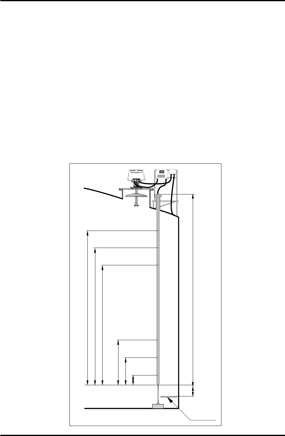
Saab TankRadar L/2
59
US Version. Seventh edition, June 1995
Installation Manual
T14
T13
T12
T3
T2
T1
L
D
DATUM
LEVEL
W11W12
FOR
INTRINSICALLY
SAFE CIRCUITS
ONLY
"i"
Figure 14.1.
Installation of
temperature
sensors.
LPG/LNG. Enter if an Inclination Device will be used. If there is a
still pipe then enter the inner diameter and the type of pipe that
will be used.
Specify to which Field Communication Unit that each tank will be
connected. If there will be a Data Acquisition Unit connected at the
tank then specify if it will be a Slave or an Independent DAU and
if it will be equipped with a Local Readout LCD Display.
The number of digital outputs have to specified and if they are to
be normally ON or normally OFF.
The number of temperature sensors and their type (Cu 100 or Pt
100) has to be entered. Other inputs can be current inputs, fre-
quency inputs or digital inputs. Specify what kind of signal that is
read at the input. Please note the heights of the Resistance Tem-
perature Detectors in the tables on pages 6-8 in the appendix. See
also figure 14.1 below.

60
Saab TankRadar L/2
US Version. Seventh edition, June 1995
Installation Manual
This page is intentionally left blank.

Saab TankRadar L/2
Appendix-1
US Version. Seventh edition, June 1995
Required System Information Form
Copyright © June 1995.
Saab Marine Electronics AB
All constants are defined in the Installation Manual, Chapter 14.
Please state all distances in metric units.
Installation site: ___________________________________________
Total number of tanks:______________________________________
Name of person who
completed this form: _______________________________________
In order to be able to correctly configure and assemble the parts of
the system the Required System Information Form must be filled
in.
It is also necessary to provide drawings of the tank farm layout
with proposed location of Radar Tank Gauges, Data Acquisition
Units, Field Communication Units, Field Bus Modems, Operator’s
Interface etc.
Note: See chapter 9 in the Installation Manual when completing the
form.
Required System Information Form
Saab TankRadar L/2
Appendix-2
US Version. Seventh edition, June 1995
Required System Information Form
System Information:
Number of FCU's:
Number of RTG's:
Number of Slave DAU's:
Number of Independent DAU's:
PC for OPI or OPI/2 Software:
Type and make (manufacturer) of PC:
Size of RAM ( OPI: Min 8 MByte, OPI/2: Min 12 MByte):
OPI Network
Number of servers in network
If existing network: Type of network
operating system
Number of clients in network
Power Supply
115 V 230 V
Connection to TRL-System:
Processor Unit Serial Number:
Plant DCS (Plant Host Computer):
Type and make (manufacturer) of computer:
Communication protocol:
Connected to FCU's or to
Operator's Interface:
Type of communication:

Saab TankRadar L/2
Appendix-3
US Version. Seventh edition, June 1995
Required System Information Form
Tank Data
Tank
Name Tank
Product Temp.
Min Max
Max
Over
Pressure
Tank
Height
Approx.
RTG Type
(2920, -30,
-40 or -60)

Saab TankRadar L/2
Appendix-4
US Version. Seventh edition, June 1995
Required System Information Form
Tank Data (Cont.)
Tank
Name If RTG 2940:
Size of
Slots/
Holes
(Ø or
WxH
in mm)
Pipe
Inner
Diam.
(mm)
Number
of Slots/
Holes
per meter
If RTG 2960:
Pipe Inner
Diameter
(Mark
with X)
Flange
Pressure
Rating
If RTG 2920
or RTG 2930:
Dist. to
Tank Wall
(mm)
DIN
100
4"
SCH
10
Socket
Height
(mm)

Saab TankRadar L/2
Appendix-5
US Version. Seventh edition, June 1995
Required System Information Form
Tank Data (Cont.)
Tank
Name Local
Readout
Display
(Yes/No)
Number
of
Temp.
Sensors:
Type of
Temp.
Sensors:
Inde-
pendent
or Slave
DAU:
Other
Inputs: Digital
Outputs
Normally
ON or
OFF:
Conn. to
FCU
name or
number:
Data Acquisition Unit, DAU Option
Option

Saab TankRadar L/2
Appendix-6
US Version. Seventh edition, June 1995
Required System Information Form
Tank Data
Specific requirements to fulfill FCC rules (Only for US markets)
Tank Name Metallic tank
(Yes/No)
Any permanent
openings
(Yes/No)
Any occasional
openings on tank
(Yes/No)
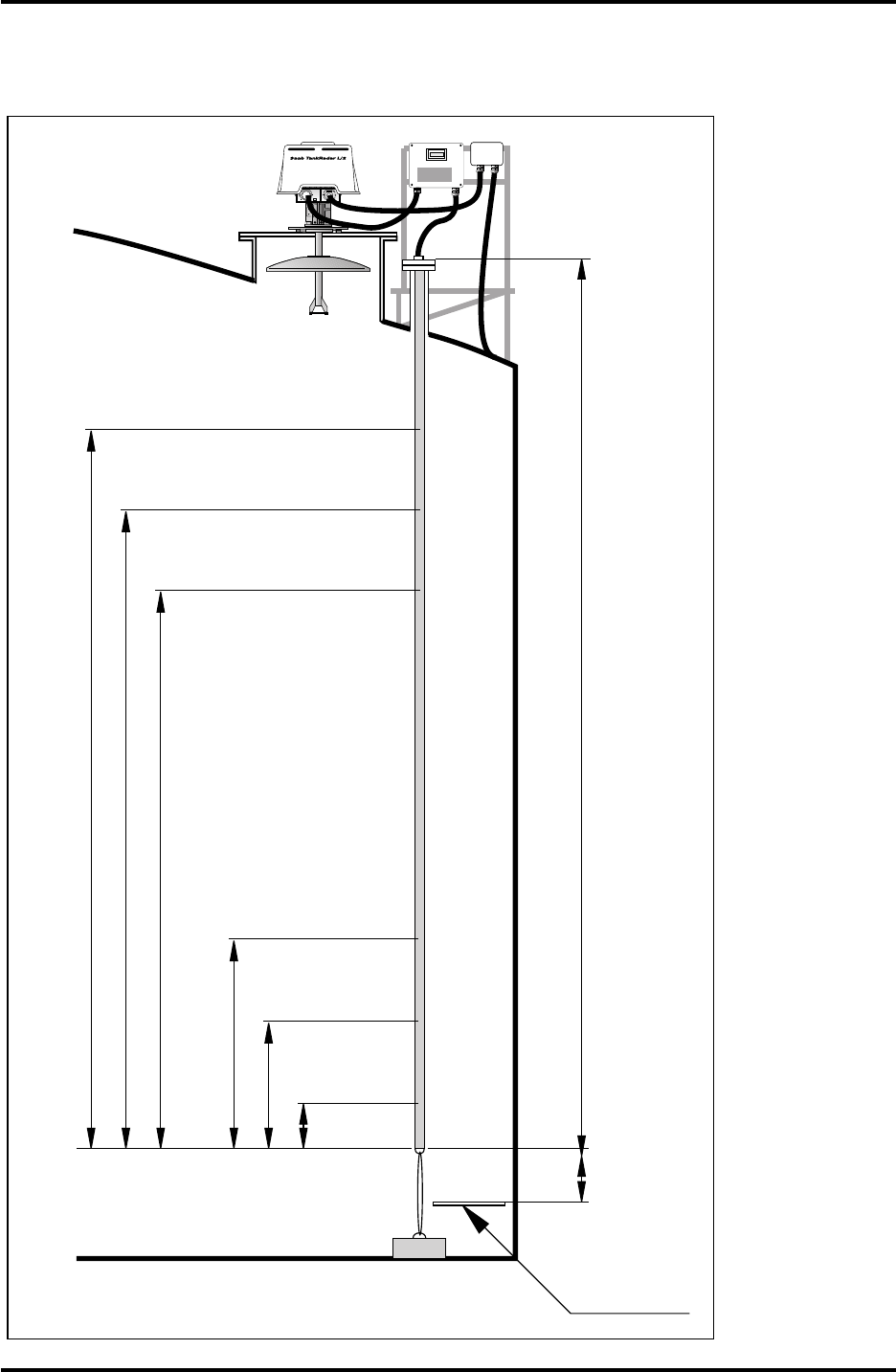
Saab TankRadar L/2
Appendix-7
US Version. Seventh edition, June 1995
Required System Information Form
Temperature Sensor Installation
T14
T13
T12
T3
T2
T1
L
D
DATUM
LEVEL
W11W12
FOR
INTRINSICALLY
SAFE CIRCUITS
ONLY
"i"

Saab TankRadar L/2
Appendix-8
US Version. Seventh edition, June 1995
Required System Information Form
Tank
Name
LD
Resistance Temperature Detectors
T1 T2 T3 T4 T5 T6 T7
Installation of Temperature Sensors (Cont.)

Saab TankRadar L/2
Appendix-9
US Version. Seventh edition, June 1995
Required System Information Form
Tank
Name
Resistance Temperature Detectors
T8 T9 T10 T11 T12 T13 T14
Installation of Temperature Sensors (Cont.)

Saab TankRadar L/2
Index 1
US Version. Seventh edition, June 1995
Installation Manual
Index
A
Analog inputs......................................55, 59
Angular Rings
Parabolic Antenna Gauge ...............44
Asphalt ..........................................16, 17, 34
B
Barrier Unit .................................................54
Barrier Unit Card .......................................14
Barrier Unit Kit...........................................14
Bitumen .........................................16, 17, 34
BU.................................................................14
C
Cable length................................................54
Cable Outputs ............................................13
Cable Requirements
Power Supply....................................53
TRL/2 Bus .........................................54
CLC ..............................................................15
Closing
LPG/LNG Gauge .............................50
Parabolic Antenna Gauge ...............44
Commissioning Check List ......................31
Communication .........................................58
Communication Ports ...............................25
Conduits......................................................42
Configuration Software ..............................9
COS ................................................................9
Cu100...........................................................59
Current Loop Card .............................15, 54
D
Data Acquisition Unit .................................9
Description ........................................20
Database......................................................58
Datum Level ...............................................58
DAU 2100.............................................22, 55
DAU 2130....................................................24
DCS .......................................................29, 58
Digital inputs..............................................59
Digital or frequency inputs ......................55
DPS board ...................................................23
E
Electrical Installation.................................53
Data Acquisition Unit ......................55
Field Bus Modem .............................56
Field Communication Unit .............56
Independent DAU............................55
List of Drawings ...............................57
Radar Tank Gauge............................54
Slave DAU .........................................55
Electronic Unit............................................13
Explosion proof................................... 10, 11
Explosion protection .................................10
Extension Pipe
LPG/LNG Gauge .............................41
F
FBM 2170.........................................9, 24, 56
FCM interface boards................................25
FCU 2160 ..................................9, 25, 27, 56
FCU Enclosure............................................26
Field Bus......................................................25
Field Bus Modem..................................9, 24
Description ........................................24
Field Communication Unit..................9, 25
Description ........................................25
Flame proof.................................................10
Flange
Parabolic Antenna Gauge ...............36
Flange Adapter...........................................47
Flange Requirements.................................38
Parabolic Antenna Gauge ...............36
Flexible conduits ........................................42
Free Space Requirement
Parabolic Antenna Gauge ........32, 35
Frequency inputs .......................................59
G
Ground ........................................................54
Grounding...................................................54
Group Bus ...................................................25

Index 2
Saab TankRadar L/2
US Version. Seventh edition, June 1995
Installation Manual
H
Hazardous area ..........................................10
Horn Antenna Gauge
Description ........................................16
Installation requirements ................32
Host computer.....................................30, 58
Housing.......................................................51
I
Inclination
Parabolic Antenna Gauge ........34, 46
Inclination Device......................................34
Parabolic Antenna Gauge ........34, 44
Independent DAU ................................9, 20
Description ........................................23
Inner diameters ..........................................38
Installation Data
Both DAUs ........................................22
Field Bus Modem .............................24
Field Communication Unit .............27
Horn Antenna Gauge.......................16
Independent DAU............................24
LPG/LNG Gauge .............................19
Parabolic Antenna Gauge ...............17
Slave DAU .........................................22
Still Pipe Gauge ................................18
Transmitter Head..............................15
Installation requirements
Cone Antenna Gauge.......................31
LPG/LNG Gauge .............................40
Parabolic Antenna Gauge ...............34
Still Pipe Gauge ................................38
Installation Schedule .................................30
Intrinsic safety ............................................10
Inventory Data ...........................................30
J
JB 12 .............................................................28
JB 16 .............................................................29
JB 36 .............................................................29
JB 8 ...............................................................28
Junction Box.........................................54, 55
Junction Boxes ............................................28
L
LCD-display .................................................9
List of Drawings.........................................57
Local Readout Display..............................21
Local Readout Display (LCD)....................9
Low-loss radar mode ................................18
LPG/LNG Gauge
Description ........................................19
Installation requirements ................40
Mechanical Installation....................50
M
Mechanical Installation
Horn Antenna Gauge.......................42
List of Drawings ...............................57
LPG/LNG Gauge .............................50
Parabolic Antenna Gauge ...............44
Still Pipe Gauge ................................47
Mechanical installation .............................42
Metrological Seal........................................15
Mouse ..........................................................58
N
New Tanks
Parabolic Antenna Gauge ...............36
Still Pipe Gauge ................................39
O
Obstacles .....................................................32
Operating system.......................................58
Operator’s Interface ........................8, 9, 58
OPI .................................................................9
OS/2.............................................................58
P
Parabolic Antenna Gauge
Description ........................................17
Installation requirements ................34
Mechanical Installation....................44
Parabolic Reflector.....................................45
Pipe Cone .............................................50, 51
Pipe inner diameter ...................................38
Pipe schedule..............................................38
Plant Host Computer ...........................8, 29
Plant Host Computer System...................58
Power Supply
Field Connection Unit......................26
Independent DAU............................23
Radar Tank Gauge............................14
Power supply .............................................53

Saab TankRadar L/2
Index 3
US Version. Seventh edition, June 1995
Installation Manual
Pressure Measurement
LPG/LNG Gauge .............................40
Pressure sealing
LPG/LNG Gauge .............................19
Protocol .......................................................58
Pt100 ............................................................59
R
Radar beam
Cone Antenna Gauge.......................32
Parabolic Antenna Gauge ........35, 37
Radar Tank Gauge .......................................9
RAM requiremnt........................................58
Reference height.........................................58
Reference Pins .......................19, 40, 41, 50
Reference Plug............................................19
Reference resistance...................................21
References
LPG/LNG Gauge .............................40
Reflector Plug .............................................40
Relay ............................................................23
Relay outputs .............................................55
Relays...........................................................23
Required System Information..................58
Required System Information Form .......31
Resistance Temperature Detectors ..........59
RS-232C .......................................................56
RS-232C Group Bus ...................................25
RTDs ............................................................20
RTG ................................................................9
RTG 2920 ..............................................16, 42
RTG 2930 ..............................................17, 44
RTG 2940 ..............................................18, 47
RTG 2960 ..............................................19, 50
S
Safety ...........................................................10
Schedule ......................................................38
Sealing Strips
Parabolic Antenna Gauge ...............44
Shielding .....................................................55
Slave Data Acquisition Unit
Description ........................................22
Slave DAU ..................................................20
Socket Requirements
Horn Antenna Gauge.......................33
Parabolic Antenna Gauge ...............37
Still pipe ...............................................40, 51
Area of the slots ................................39
LPG/LNG Gauge .............................50
Still Pipe Gauge..........................................18
Description ........................................18
Installation requirements ................38
Mechanical Installation....................47
Still Pipe Requirements.............................38
Supply voltage switch
Data Acquisition Unit ......................23
Field Communication Unit .............26
Radar Tank Gauge............................14
System Configuration ...............................58
System Master ............................................58
T
Tank Data ....................................................58
Tank Reference Height ..............................58
Tank Reference Point.................................58
Temperature Measurement
LPG/LNG Gauge .............................40
Temperature measurement................20, 21
Temperature Range ...................................21
Temperature sensors....................20, 55, 59
Transition Cone ..........................................38
Transmitter Head .......................................12
V
Voltage drop ...............................................53
Voltage selection ........................................53
Voltage switch ............................................53
W
W11 ..............................................................54
W12 ..............................................................54
Waveguide Connection.............................49
Waveguide Unit
LPG/LNG Gauge .............................51
Parabolic Antenna Gauge ...............44
Still Pipe Gauge ................................48
Welding neck flange ..................................36
Write Inhibit/Enable Switch
DAUs..................................................21
Field Connection Unit......................26

Index 4
Saab TankRadar L/2
US Version. Seventh edition, June 1995
Installation Manual
Notes: