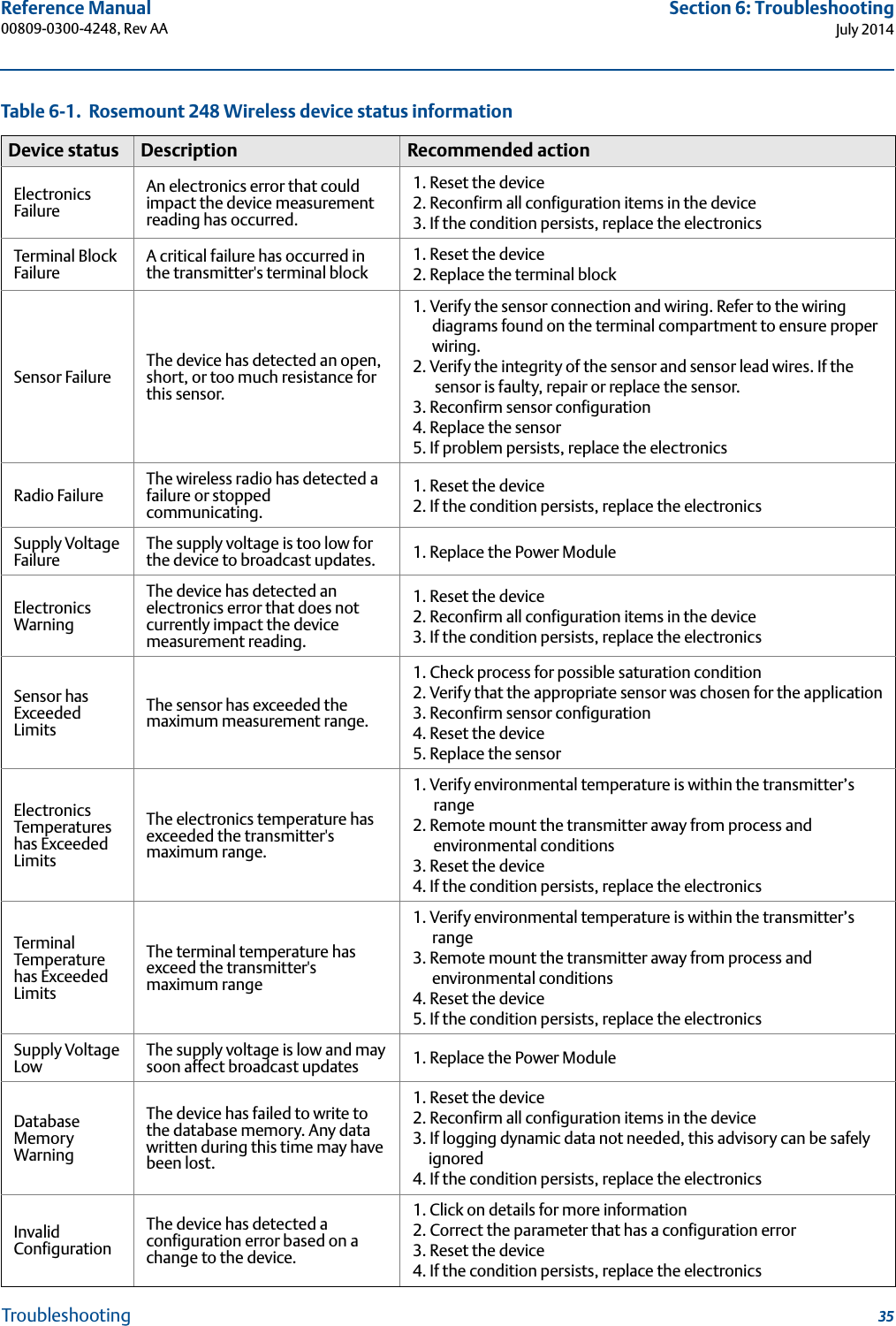
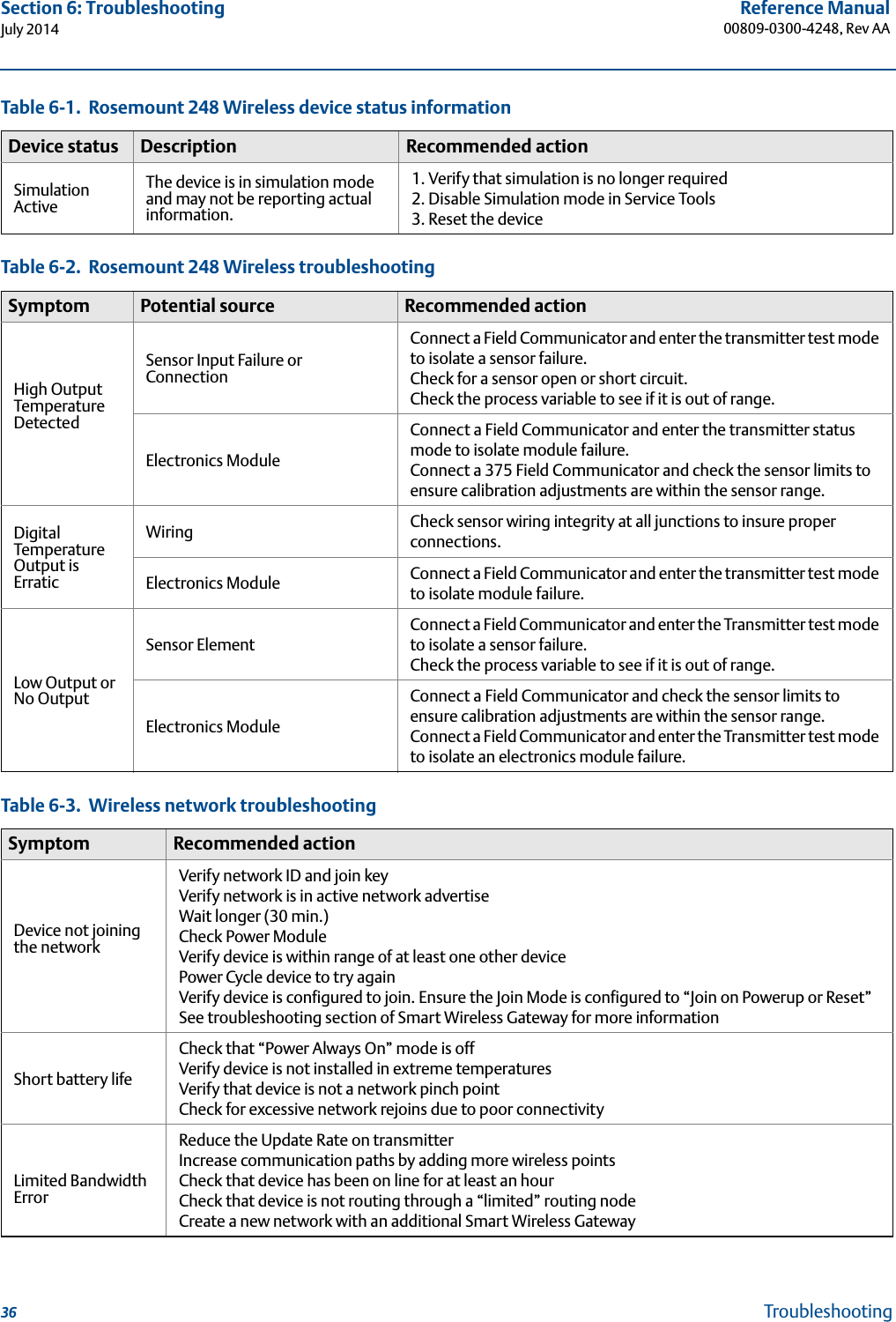
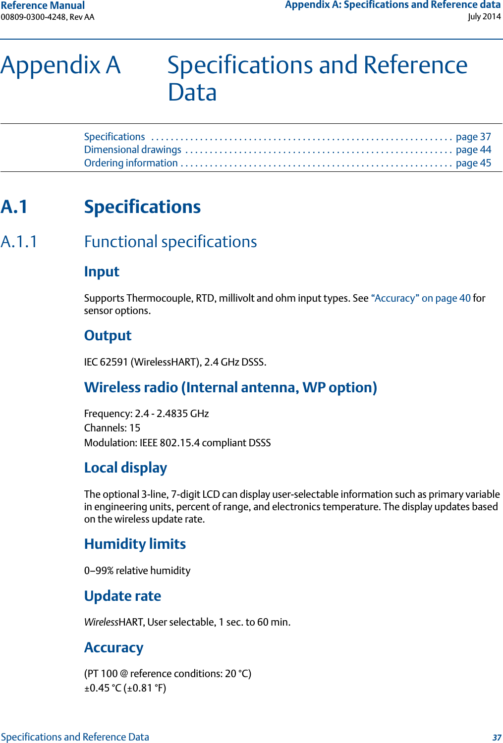
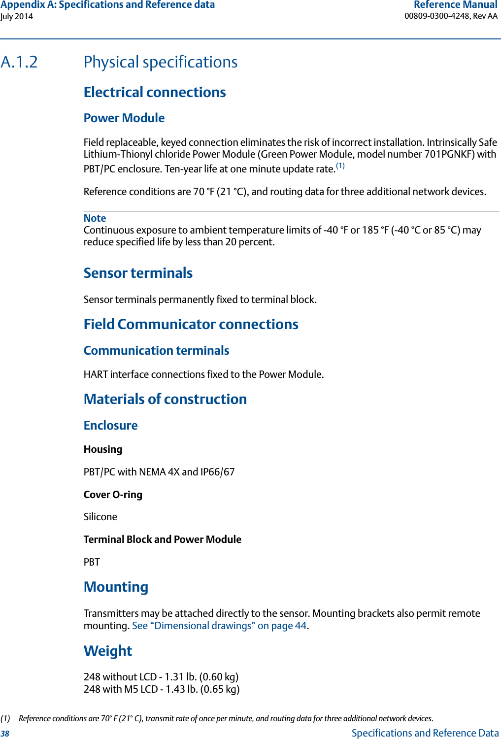
Rosemount 248DX Wireless Industial Temperature Transmitter User Manual 00809 0300 4248 RevAA

Rosemount Inc Wireless Industial Temperature Transmitter 00809 0300 4248 RevAA

User Manual

Reference Manual00809-0300-4248, Rev AAJuly 2014Rosemount 248 Wireless Temperature Transmitter
iiiReference Manual 00809-0300-4248, Rev AARosemount 248 WirelessTemperature TransmitterRosemount 248 Hardware RevisionHART® Device RevisionField Communicator Field Device Revision11Dev 1, DD v1NOTICERead this manual before working with the product. For personal and system safety, and for optimum product performance, make sure to thoroughly understand the contents before installing, using or maintaining this product.For technical assistance, contacts are listed below:Customer CentralTechnical support, quoting, and order-related questions.United States - 1-800-999-9307 (7:00 am to 7:00 pm CST)Asia Pacific- 65 777 8211Europe/ Middle East/ Africa - 49 (8153) 9390North American Response CenterEquipment service needs1-800-654-7768 (24 hours—includes Canada)Outside of these areas, contact your local Emerson Process Management representative.The products described in this document are NOT designed for nuclear-qualified applications. Using non-nuclear qualified products in applications that require nuclear-qualified hardware or products may cause inaccurate readings. For information on Rosemount nuclear-qualified products, contact a Emerson Process Management Sales Representative.
ivReference Manual00809-0300-4248, Rev AAFailure to follow these installation guidelines could result in death or serious injury:Make sure only qualified personnel perform the installation.Explosions could result in death or serious injury: Installation of this transmitter in an explosive environment must be in accordance with the appropriate local, national, and international standards, codes, and practices. Please review the approvals section of the 248 reference manual for any restrictions associated with a safe installation. Before connecting a Field Communicator in an explosive atmosphere, ensure the instruments are installed in accordance with intrinsically safe or non-incendive field wiring practices.Verify that the operating atmosphere of the transmitter is consistent with the appropriate hazardous locations certifications.Process leaks may cause harm or result in death. Do not remove the thermowell while in operation.Install and tighten thermowells and sensors before applying pressure.Electrical shock can result in death or serious injury.Avoid contact with the leads and terminals. High voltage that may be present on leads can cause electrical shock.This device complies with Part 15 of the FCC Rules. Operation is subject to the following conditions:This device may not cause harmful interference. This device must accept any interference received, including interference that may cause undesired operation. This device must be installed to ensure a minimum antenna separation distance of 20 cm from all persons.The Power Module may be replaced in a hazardous area. The Power Module has surface resistivity greater than one gigaohm and must be properly installed in the wireless device enclosure. Care must be taken during transportation to and from the point of installation to prevent electrostatic charge build-up.NOTICEThe Rosemount 248 Wireless and all other wireless devices should be installed only after the Smart Wireless Gateway has been installed and is functioning properly. Wireless devices should also be powered up in order of proximity from the Smart Wireless Gateway, beginning with the closest. This will result in a simpler and faster network installation.
vReference Manual 00809-0300-4248, Rev AANOTICEShipping considerations for wireless products (Lithium Batteries: Green Power Module, model number 701PGNKF):The unit was shipped to you without the Power Module installed. Please remove the Power Module prior to shipping the unit.Each Power Module contains one “D” size primary lithium-thionyl chloride battery. Primary lithium batteries are regulated in transportation by the U. S. Department of Transportation, and are also covered by IATA (International Air Transport Association), ICAO (International Civil Aviation Organization), and ARD (European Ground Transportation of Dangerous Goods). It is the responsibility of the shipper to ensure compliance with these or any other local requirements. Please consult current regulations and requirements before shipping.NOTICEPower Module Considerations:The power module with the wireless unit contains one “D” size primary lithium-thionyl chloride battery (Green Power Module, model number 701PGNKF). Each battery contains approximately 5.0 grams of lithium. Under normal conditions, the battery materials are self-contained and are not reactive as long as the batteries and the pack integrity are maintained. Care should be taken to prevent thermal, electrical or mechanical damage. Contacts should be protected to prevent premature discharge.Battery hazards remain when cells are discharged.Power Modules should be stored in a clean and dry area. For maximum Power Module life, storage temperature should not exceed 30 °C.
viiReference Manual 00809-0300-4248, Rev AATable of ContentsJuly 2014Table of Contents 1Section 1: Introduction1.1 Using this manual. . . . . . . . . . . . . . . . . . . . . . . . . . . . . . . . . . . . . . . . . . . . . . . . . . . . . . .11.2 Safety messages. . . . . . . . . . . . . . . . . . . . . . . . . . . . . . . . . . . . . . . . . . . . . . . . . . . . . . . .21.2.1 Warnings  . . . . . . . . . . . . . . . . . . . . . . . . . . . . . . . . . . . . . . . . . . . . . . . . . . . . . . . .21.3 Considerations . . . . . . . . . . . . . . . . . . . . . . . . . . . . . . . . . . . . . . . . . . . . . . . . . . . . . . . . .31.3.1 General . . . . . . . . . . . . . . . . . . . . . . . . . . . . . . . . . . . . . . . . . . . . . . . . . . . . . . . . . .31.3.2 Commissioning . . . . . . . . . . . . . . . . . . . . . . . . . . . . . . . . . . . . . . . . . . . . . . . . . . .31.3.3 Mechanical. . . . . . . . . . . . . . . . . . . . . . . . . . . . . . . . . . . . . . . . . . . . . . . . . . . . . . .41.3.4 Electrical . . . . . . . . . . . . . . . . . . . . . . . . . . . . . . . . . . . . . . . . . . . . . . . . . . . . . . . . .41.3.5 Environmental. . . . . . . . . . . . . . . . . . . . . . . . . . . . . . . . . . . . . . . . . . . . . . . . . . . .41.4 Service support. . . . . . . . . . . . . . . . . . . . . . . . . . . . . . . . . . . . . . . . . . . . . . . . . . . . . . . . .51.5 Product recycling/disposal . . . . . . . . . . . . . . . . . . . . . . . . . . . . . . . . . . . . . . . . . . . . . . .6 2Section 2: Configuration2.1 Overview . . . . . . . . . . . . . . . . . . . . . . . . . . . . . . . . . . . . . . . . . . . . . . . . . . . . . . . . . . . . . .72.2 Safety messages. . . . . . . . . . . . . . . . . . . . . . . . . . . . . . . . . . . . . . . . . . . . . . . . . . . . . . . .72.2.1 Warnings  . . . . . . . . . . . . . . . . . . . . . . . . . . . . . . . . . . . . . . . . . . . . . . . . . . . . . . . .82.3 Sensor connections . . . . . . . . . . . . . . . . . . . . . . . . . . . . . . . . . . . . . . . . . . . . . . . . . . . . .92.4 Bench top configuration . . . . . . . . . . . . . . . . . . . . . . . . . . . . . . . . . . . . . . . . . . . . . . . .122.5 Device network configuration . . . . . . . . . . . . . . . . . . . . . . . . . . . . . . . . . . . . . . . . . . .142.5.1 Join to network  . . . . . . . . . . . . . . . . . . . . . . . . . . . . . . . . . . . . . . . . . . . . . . . . . .142.5.2 Configure update rate . . . . . . . . . . . . . . . . . . . . . . . . . . . . . . . . . . . . . . . . . . . .142.5.3 HART menu tree . . . . . . . . . . . . . . . . . . . . . . . . . . . . . . . . . . . . . . . . . . . . . . . . .152.5.4 Fast Key sequence  . . . . . . . . . . . . . . . . . . . . . . . . . . . . . . . . . . . . . . . . . . . . . . .182.5.5 Calibration . . . . . . . . . . . . . . . . . . . . . . . . . . . . . . . . . . . . . . . . . . . . . . . . . . . . . .182.6 Remove power module. . . . . . . . . . . . . . . . . . . . . . . . . . . . . . . . . . . . . . . . . . . . . . . . .20 3Section 3: Installation3.1 Safety messages. . . . . . . . . . . . . . . . . . . . . . . . . . . . . . . . . . . . . . . . . . . . . . . . . . . . . . .213.1.1 Warnings  . . . . . . . . . . . . . . . . . . . . . . . . . . . . . . . . . . . . . . . . . . . . . . . . . . . . . . .213.2 Wireless consideration  . . . . . . . . . . . . . . . . . . . . . . . . . . . . . . . . . . . . . . . . . . . . . . . . .223.2.1 Power up sequence  . . . . . . . . . . . . . . . . . . . . . . . . . . . . . . . . . . . . . . . . . . . . . .223.2.2 Internal antenna position  . . . . . . . . . . . . . . . . . . . . . . . . . . . . . . . . . . . . . . . . .223.3 Field Communicator connections. . . . . . . . . . . . . . . . . . . . . . . . . . . . . . . . . . . . . . . .223.4 Mounting . . . . . . . . . . . . . . . . . . . . . . . . . . . . . . . . . . . . . . . . . . . . . . . . . . . . . . . . . . . . .23Contents
viiiReference Manual00809-0300-4248, Rev AATable of ContentsJuly 2014Table of Contents3.5 Physical installation . . . . . . . . . . . . . . . . . . . . . . . . . . . . . . . . . . . . . . . . . . . . . . . . . . . .233.5.1 Direct mount . . . . . . . . . . . . . . . . . . . . . . . . . . . . . . . . . . . . . . . . . . . . . . . . . . . .243.5.2 Remote mount  . . . . . . . . . . . . . . . . . . . . . . . . . . . . . . . . . . . . . . . . . . . . . . . . . .24 4Section 4: Commissioning4.1 Safety messages. . . . . . . . . . . . . . . . . . . . . . . . . . . . . . . . . . . . . . . . . . . . . . . . . . . . . . .254.1.1 Warnings  . . . . . . . . . . . . . . . . . . . . . . . . . . . . . . . . . . . . . . . . . . . . . . . . . . . . . . .254.2 Verify operations  . . . . . . . . . . . . . . . . . . . . . . . . . . . . . . . . . . . . . . . . . . . . . . . . . . . . . .264.2.1 Field Communicator. . . . . . . . . . . . . . . . . . . . . . . . . . . . . . . . . . . . . . . . . . . . . .264.2.2 Emerson Smart Wireless Gateway. . . . . . . . . . . . . . . . . . . . . . . . . . . . . . . . . .264.3 AMS™ Wireless Configurator  . . . . . . . . . . . . . . . . . . . . . . . . . . . . . . . . . . . . . . . . . . . .274.4 Troubleshooting. . . . . . . . . . . . . . . . . . . . . . . . . . . . . . . . . . . . . . . . . . . . . . . . . . . . . . .284.5 Reference information  . . . . . . . . . . . . . . . . . . . . . . . . . . . . . . . . . . . . . . . . . . . . . . . . .28 5Section 5: Operation and Maintenance5.1 Safety messages. . . . . . . . . . . . . . . . . . . . . . . . . . . . . . . . . . . . . . . . . . . . . . . . . . . . . . .295.1.1 Warnings  . . . . . . . . . . . . . . . . . . . . . . . . . . . . . . . . . . . . . . . . . . . . . . . . . . . . . . .295.2 Power module replacement. . . . . . . . . . . . . . . . . . . . . . . . . . . . . . . . . . . . . . . . . . . . .305.3 LCD screen messages  . . . . . . . . . . . . . . . . . . . . . . . . . . . . . . . . . . . . . . . . . . . . . . . . . .315.3.1 Startup screen sequence . . . . . . . . . . . . . . . . . . . . . . . . . . . . . . . . . . . . . . . . . .31 6Section 6: Troubleshooting6.1 Overview . . . . . . . . . . . . . . . . . . . . . . . . . . . . . . . . . . . . . . . . . . . . . . . . . . . . . . . . . . . . .336.2 Safety messages. . . . . . . . . . . . . . . . . . . . . . . . . . . . . . . . . . . . . . . . . . . . . . . . . . . . . . .336.2.1 Warnings  . . . . . . . . . . . . . . . . . . . . . . . . . . . . . . . . . . . . . . . . . . . . . . . . . . . . . . .34 AAppendix A: Specifications and Reference DataA.1 Specifications . . . . . . . . . . . . . . . . . . . . . . . . . . . . . . . . . . . . . . . . . . . . . . . . . . . . . . . . .37A.1.1 Functional specifications. . . . . . . . . . . . . . . . . . . . . . . . . . . . . . . . . . . . . . . . . .37A.1.2 Physical specifications . . . . . . . . . . . . . . . . . . . . . . . . . . . . . . . . . . . . . . . . . . . .38A.1.3 Performance specifications. . . . . . . . . . . . . . . . . . . . . . . . . . . . . . . . . . . . . . . .39A.1.4 Accuracy   . . . . . . . . . . . . . . . . . . . . . . . . . . . . . . . . . . . . . . . . . . . . . . . . . . . . . . .40A.1.5 Ambient temperature effect  . . . . . . . . . . . . . . . . . . . . . . . . . . . . . . . . . . . . . .41A.1.6 Lead wire resistance effect  . . . . . . . . . . . . . . . . . . . . . . . . . . . . . . . . . . . . . . . .43A.2 Dimensional drawings. . . . . . . . . . . . . . . . . . . . . . . . . . . . . . . . . . . . . . . . . . . . . . . . . .44A.3 Ordering information  . . . . . . . . . . . . . . . . . . . . . . . . . . . . . . . . . . . . . . . . . . . . . . . . . .45
ixReference Manual 00809-0300-4248, Rev AATable of ContentsJuly 2014Table of Contents BAppendix B: Product CertificationsB.1 Approved Manufacturing Locations . . . . . . . . . . . . . . . . . . . . . . . . . . . . . . . . . . . . . .47B.2 European Directive Information  . . . . . . . . . . . . . . . . . . . . . . . . . . . . . . . . . . . . . . . . .47B.3 Ordinary Location Certification from FM Approvals  . . . . . . . . . . . . . . . . . . . . . . . .47 CAppendix C: Mapping for non-DD based Integration with Host SystemsC.1 Mapping of alert messages in the HART command 48 additional status  . . . . . .49C.2 Mapping of device variables index numbers . . . . . . . . . . . . . . . . . . . . . . . . . . . . . . .50
xReference Manual00809-0300-4248, Rev AATable of ContentsJuly 2014Table of Contents
Reference Manual 00809-0300-4248, Rev AASection 1: IntroductionJuly 20141IntroductionSection 1 Introduction1.1 Using this manualThe sections in this manual provide information on installing, operating, and maintaining the Rosemount 248 Wireless temperature transmitter with WirelessHART® protocol. The sections are organized as follows: Section 2: Configuration provides instruction on commissioning and operating 248 Wireless transmitters. Information on software functions, configuration parameters, and on line variables is also included.Section 3: Installation contains mechanical and electrical installation instructions.Section 4: Commissioning contains techniques for properly commissioning the device.Section 5: Operation and Maintenance contains operation and maintenance techniques.Section 6: Troubleshooting provides troubleshooting techniques for the most common operating problems.Appendix A: Specifications and Reference Data supplies reference and specification data, as well as ordering information.Appendix B: Product Certifications contains approval information.Appendix C: Mapping for non-DD based Integration with Host SystemsRosemount 248 Wireless TransmitterFeatures of the Rosemount 248 Wireless include:An installation-ready solution that provides a variety of mounting options, transmitter configurations, and sensors/thermowellsFlexibility to meet your most demanding applicationsWireless output with >99% data reliability delivers rich HART data, protected by industry leading securitySimple and easy installation practices already used today for robust installationsRefer to the following literatures for a full range of compatible connection heads, sensors, and thermowells provided by Emerson Process Management.English Temperature Sensors and Assemblies Product Data Sheet, Volume 1 (document number 00813-0100-2654)Temperature Sensors and Accessories (Metric Sensors) Product Data Sheet, Volume 2 (document number 00813-0200-2654)
2Reference Manual00809-0300-4248, Rev AASection 1: IntroductionJuly 2014Introduction1.2 Safety messagesInstructions and procedures in this section may require special precautions to ensure the safety of the personnel performing the operations. Information that potentially raises safety issues is indicated by a warning symbol ( ). Please refer to the following safety messages before performing an operation preceded by this symbol.1.2.1 WarningsFailure to follow these installation guidelines could result in death or serious injury. Make sure only qualified personnel perform the installation.Explosions could result in death or serious injury. Before connecting a Field Communicator in an explosive atmosphere, make sure the instruments are installed in accordance with intrinsically safe or non-incendive field wiring practices.Verify that the operating atmosphere of the transmitter is consistent with the appropriate hazardous locations certifications.Process leaks could result in death or serious injury. Do not remove the thermowell while in operation.Install and tighten thermowells and sensors before applying pressureElectrical shock could cause death or serious injury. Avoid contact with the leads and terminals. High voltage that may be present on leads can cause electrical shock.This device complies with Part 15 of the FCC Rules. Operation is subject to the following conditions.This device may not cause harmful interference.This device must accept any interference received, including interference that may cause undesired operations.This device must be installed to ensure a minimum antenna separation distance of 20 cm from all person.The Power Module may be replaced in a hazardous area. The Power Module has surface resistivity greater than one gigaohm and must be properly installed in the wireless device enclosure. Care must be taken during transportation to and from the point of installation to prevent electrostatic charge build-up.
3Reference Manual 00809-0300-4248, Rev AASection 1: IntroductionJuly 2014Introduction1.3 Considerations1.3.1 GeneralElectrical temperature sensors such as RTDs and thermocouples produce low-level signals proportional to their sensed temperature. With simple HART configuration, the Rosemount 248 Wireless converts the low-level sensor signal to a wireless-enabled signal.1.3.2 CommissioningThe transmitter can be commissioned before or after installation. It may be useful to commission it on the bench, before installation, to ensure proper operation and to become familiar with its functionality. When applicable, make sure the instruments are installed in accordance with intrinsically safe or non-incendive field wiring practices. The device will be powered whenever the power module is installed. To avoid depleting the Power Module, make sure it is removed when the device is not in use.Power up sequenceThe Power Module should not be installed on any wireless device until the Smart Wireless Gateway is installed and functioning properly. This transmitter uses the Green Power Module (order model number 701PGNKF). Wireless devices should also be powered up in order of proximity from the Smart Wireless Gateway, beginning with the closest. This will result in a simpler and faster network installation. Enable Active Advertising on the Gateway to ensure that new devices join the network faster. For more information, see the Smart Wireless Gateway Manual (Doc. No. 00809-0200-4420).Internal antenna positionThe internal antenna is designed for multiple mounting orientations. The transmitter should be mounted according to best practices for your temperature measurement application. The antenna should be approximately 3 ft (1 m) from any large structure or building to allow clear communication to other devices.Network design best practicesWhen mounting the device, recommended practices should be considered to achieve the best wireless performance. See “Mounting” on page 23 for more information on recommended practices.Field Communicator connectionsThe Power Module needs to be installed in the device for the Field Communicator to interface with the Rosemount 248 Wireless Temperature Transmitter. The Field Communicator connections are located on the Power Module. To communicate to the transmitter, connect the Field Communicator to the COMM port connections on the Power Module. This transmitter uses the Green Power Module; please order model number 701PGNKF. Field communication with this device requires a HART-based Field Communicator using the correct Rosemount 248 Wireless DD. The Power Module is keyed and can only be inserted in one orientation. Refer to Figure 3-1 for instructions on connecting the Field Communicator to the 248.
4Reference Manual00809-0300-4248, Rev AASection 1: IntroductionJuly 2014Introduction1.3.3 MechanicalLocationWhen choosing an installation location and position, take into account the need for access to the mesh network, access to the transmitter and to the power module compartment for ease power module replacement.Electronics coverThe electronics cover is tightened so that polymer contacts polymer. When removing the electronics cover, ensure that there is no damage done to the o-ring. If damaged replace before reattaching cover, ensuring polymer contacts polymer (i.e. no o-ring visible).1.3.4 Electrical Power ModuleThe Rosemount 248 Wireless Temperature transmitter is self-powered. The Power Module contains a primary lithium-thionyl chloride battery (Green Power Module, model number 701PGNKF). Each battery contains approximately 5 grams of lithium. Under normal conditions, the battery materials are self-contained and are not reactive as long as the battery and the Power Module are maintained. Care should be taken to prevent thermal, electrical, or mechanical damage. Contacts should be protected to prevent premature discharge.Use caution when handling the power module, it may be damaged if dropped from heights in excess of 20 feet.Battery hazards remain when cells are discharged.Power Modules should be stored in a clean and dry area. For maximum Power Module life, storage temperature should not exceed 30 °C.SensorMake sensor connections with the threaded 1/2-inch. NPT connection sensor adapter.1.3.5 EnvironmentalVerify that the operating atmosphere of the transmitter is consistent with the appropriate hazardous locations certifications.Temperature effects The transmitter will operate within specifications for ambient temperatures between –40 and 185 °F (–40 and 85 °C). Heat from the process is transferred from the thermowell to the transmitter housing. If the expected process temperature is near or beyond specification limits, consider the use of additional thermowell and extension, or remote mounting the transmitter to thermally isolate it from the process.
5Reference Manual 00809-0300-4248, Rev AASection 1: IntroductionJuly 2014IntroductionTemperature limits1.4 Service supportTo expedite the return process outside of the United States, contact the nearest Emerson Process Management representative.Within the United States, call the Emerson Process Management Instrument and Valves Response Center using the 1-800-654-RSMT (7768) toll-free number. This center, available 24 hours a day, will assist you with any needed information or materials.The center will ask for the following information:Product model Serial numbersThe last process material to which the product was exposedThe center will provide:A Return Material Authorization (RMA) numberInstructions and procedures that are necessary to return goods that were exposed to hazardous substancesNoteIf the device has been exposed to a hazardous substance, a Material Safety Data Sheet (MSDS) must be included with the returned materials. An MSDS is required by law to be available to people exposed to specific hazardous substances.Operating limit Storage limit–40 to 185 °F –40 to 185 °F–40 to 85 °C –40 to 85 °CIndividuals who handle products exposed to a hazardous substance can avoid injury if they are informed of and understand the hazard. If the product being returned was exposed to a hazardous substance as defined by OSHA, a copy of the required Material Safety Data Sheet (MSDS) for each hazardous substance identified must be included with the returned goods.
6Reference Manual00809-0300-4248, Rev AASection 1: IntroductionJuly 2014Introduction1.5 Product recycling/disposalRecycling of equipment and packaging should be taken into consideration and disposed of in accordance with local and national legislation/regulations.NOTICEShipping considerations for wireless products (Lithium Batteries: Green Power Module, model number 701PGNKF):The unit was shipped to you without the Power Module installed. Please remove the Power Module prior to shipping the unit.Each power module contains a primary lithium-thionyl chloride battery. Primary lithium batteries are regulated in transportation by the U. S. Department of Transportation, and are also covered by IATA (International Air Transport Association), ICAO (International Civil Aviation Organization), and ARD (European Ground Transportation of Dangerous Goods). It is the responsibility of the shipper to ensure compliance with these or any other local requirements. Please consult current regulations and requirements before shipping.
Reference Manual 00809-0300-4248, Rev AASection 2: ConfigurationJuly 20147ConfigurationSection 2 ConfigurationOverview   . . . . . . . . . . . . . . . . . . . . . . . . . . . . . . . . . . . . . . . . . . . . . . . . . . . . . . . . . . . . . . . . . .  page 7Safety messages  . . . . . . . . . . . . . . . . . . . . . . . . . . . . . . . . . . . . . . . . . . . . . . . . . . . . . . . . . . . .  page 7Warnings   . . . . . . . . . . . . . . . . . . . . . . . . . . . . . . . . . . . . . . . . . . . . . . . . . . . . . . . . . . . . . . . . . .  page 8Sensor connections  . . . . . . . . . . . . . . . . . . . . . . . . . . . . . . . . . . . . . . . . . . . . . . . . . . . . . . . . .  page 9Bench top configuration  . . . . . . . . . . . . . . . . . . . . . . . . . . . . . . . . . . . . . . . . . . . . . . . . . . . . .  page 12Device network configuration  . . . . . . . . . . . . . . . . . . . . . . . . . . . . . . . . . . . . . . . . . . . . . . . .  page 14HART menu tree  . . . . . . . . . . . . . . . . . . . . . . . . . . . . . . . . . . . . . . . . . . . . . . . . . . . . . . . . . . . .  page 152.1 OverviewThis section contains information on configuration and verification that should be performed prior to installation.Field Communicator and AMS instructions are given to perform configuration functions. For convenience, Field Communicator fast key sequences are labeled “Fast Keys” for each software function below the appropriate headings.Sensor Input Trim example2.2 Safety messagesInstructions and procedures in this section may require special precautions to ensure the safety of the personnel performing the operations. Information that potentially raises safety issues is indicated by a warning symbol ( ). Please refer to the following safety messages before performing an operation preceded by this symbol.Electrical grounds are indicated on drawings by a ground symbol ( ). Always follow proper grounding practices.Fast Key sequence 1, 2, 3, etc.
8Reference Manual00809-0300-4248, Rev AASection 2: ConfigurationJuly 2014Configuration2.2.1 WarningsFailure to follow these installation guidelines could result in death orserious injury. Make sure only qualified personnel perform the installation.Explosions could result in death or serious injury. Before connecting a Field Communicator in an explosive atmosphere, make sure the instruments are installed in accordance with intrinsically safe or non-incendive field wiring practices.Verify that the operating atmosphere of the transmitter is consistent with the appropriate hazardous locations certifications.Process leaks could result in death or serious injury. Do not remove the thermowell while in operation.Install and tighten thermowells and sensors before applying pressureElectrical shock could cause death or serious injury. Avoid contact with the leads and terminals. High voltage that may be present on leads can cause electrical shock.This device complies with Part 15 of the FCC Rules. Operation is subject to the following conditions:This device may not cause harmful interference. This device must accept any interference received, including interference that may cause undesired operation. This device must be installed to ensure a minimum antenna separation distance of 20 cm from all persons.The Power Module may be replaced in a hazardous area. The Power Module has surface resistivity greater than one gigaohm and must be properly installed in the wireless device enclosure. Care must be taken during transportation to and from the point of installation to prevent electrostatic charge build-up.
9Reference Manual 00809-0300-4248, Rev AASection 2: ConfigurationJuly 2014Configuration2.3 Sensor connectionsThe 248 Wireless is compatible with a number of RTD and thermocouple sensor types. Figure 2-1 shows the correct input connections to the sensor terminals on the transmitter. To ensure a proper sensor connection, anchor the sensor lead wires into the appropriate compression terminals and tighten the screws.Thermocouple or Millivolts inputsThe thermocouple can be connected directly to the transmitter. Use appropriate thermocouple extension wire if mounting the transmitter remotely from the sensor. RTD or Ohm inputsThe transmitters will accept a variety of RTD or ohmic configurations, including 2-wire, 3-wire or 4-wire connections. If the transmitter is mounted remotely from a 3-wire or 4-wire RTD, it will operate within specifications, without recalibration, for lead wire resistances of up to 5 ohms per lead (equivalent to 500 feet of 20 AWG wire). In this case, the leads between the RTD and transmitter should be shielded. If using a 2-wire connection, both RTD leads are in series with the sensor element, so significant errors can occur if the lead lengths exceed three feet of 20 AWG wire (approximately 0.05 C/ft.). For longer runs, attach a third or fourth lead to achieve a 3-wire or 4-wire connection as described above.Effect-RTD inputSince the lead wires are part of the RTD circuit, the lead wire resistance needs to be compensated for to achieve the best accuracy. This becomes especially critical in applications where long sensor and/or lead wires are used. There are three lead wire configurations commonly available. In a two-wire configuration there can be no compensation for lead wire resistance since the lead wires are in series with the element and appear to the transmitter as part of the sensor's resistance causing inherent accuracy degradation. In a three-wire configuration, compensation is accomplished using the third wire with the assumption that it will be the same resistance as the other two wires and the same compensation is applied to all three wires. A four-wire design is ideal because the lead wire resistance is inconsequential to the measurement. It uses a measurement technique where a very small constant current of about 150 micro amps is applied to the sensor through two leads and the voltage developed across the sensor is measured over the other two wires with a high-impedance and high resolution measuring circuit. In accordance with Ohm's Law, the high impedance virtually eliminates any current flow in the voltage measurement leads and therefore the resistance of the leads is not a factor.Table 2-1.  Examples of Approximate Basic ErrorSensor input Approximate basic error4-wire RTD Negligible(1)(1) Independent of lead wire resistance up to 5 per lead.3-wire RTD Error in reading is equivalent to unbalanced lead wire resistance(2)(2) Unbalanced lead wire resistance is the maximum resistance differences between any two leads.2-wire RTD Error in reading is equivalent to total lead wire resistance
10Reference Manual00809-0300-4248, Rev AASection 2: ConfigurationJuly 2014ConfigurationFigure 2-1. Sensor Wiring DiagramsNoteEmerson Process Management provides 4-wire sensors for all single element RTDs. Use these RTDs in 3-wire or 2-wire configurations by leaving the unneeded leads disconnected and insulated with electrical tape.Figure 2-2. Rosemount 65, 68Q, 78 Standard and High Temp, 58C and 68 RTD Lead Wire ConfigurationsFigure 2-3. Rosemount 183 Thermocouple Lead Wire Configuration248 Wireless sensor connections diagramSingle elementA. White (1) C. Red (3)B. White (2) D. Red (4)Type J Type EType K Type TA. White (2) E. Purple (2)B. Red (3) F. Red (3)C. Yellow (2) G. Blue (2)D. Red (3) H. Red (3)T/C and mV4-wire RTD and 3-wire RTD and 2-wire RTD and 2341234123412341ABCD+A–B+E–F+C–D+G–H
11Reference Manual 00809-0300-4248, Rev AASection 2: ConfigurationJuly 2014ConfigurationFigure 2-4. Rosemount 185 Thermocouple Lead Wire ConfigurationsNoteWire color examples apply to Rosemount sensors, but will vary by manufacturer.Sensor leadsIf the sensor is installed in a high-voltage environment and a fault condition or installation error occurs, the sensor leads and transmitter terminals could carry lethal voltages. Use extreme caution when making contact with the leads and terminals.Use the following steps to wire the sensor and supply power to the transmitter:1. Remove the transmitter enclosure cover (if applicable).2. Attach the sensor leads according to the wiring diagrams.3. Connect the Power Module.4. Verify the connection.5. Reattach and tighten the cover (if applicable).Type J Type NType KA. Black (2) E. Red (2)B. White (3) F. White (3)C. Green (2)D. White (3)+A–B+E–F+C–D
12Reference Manual00809-0300-4248, Rev AASection 2: ConfigurationJuly 2014Configuration2.4 Bench top configurationBench top configuration requires a Field Communicator, AMS, or any WirelessHART Communicator. Connect the Field Communicator leads to the terminals labeled “COMM” on the Power Module.Bench top configuration consists of testing the transmitter and verifying transmitter configuration data. 248 Wireless transmitters must be configured before installation. Configuring the transmitter on the bench before installation using a Field Communicator, AMS, or any WirelessHART Communicator ensures that all network settings are working correctly. When using a Field Communicator, any configuration changes made must be sent to the transmitter by using the Send key (F2). AMS configuration changes are implemented when the Apply button is clicked.Field CommunicatorIf performing device configuration directly, connect the bench equipment and turn on the Field Communicator by pressing the ON/OFF key. When using a Field Communicator, any configuration changes must be sent to the transmitter by using the Send key (F2).The Field Communicator will search for a HART-compatible device and indicate when the connection is made. If the Field Communicator fails to connect, it will indicate that no device was found. If this occurs, refer to Section 6: Troubleshooting.AMS™ Device Manager and AMS Wireless ConfiguratorWhen configuring the Rosemount 248 Wireless using AMS Device Manager or AMS Wireless Configurator, double click the Rosemount 248 Wireless device icon (or right click and select Con/Setup), then choose the Configure Menu. AMS configuration changes are implemented when the Apply button is clicked.During direct connection configuration, AMS will search for a HART-compatible device and indicate when the connection is made. If AMS fails to connect, it indicates that no device was found. If this occurs, refer to Section 6: Troubleshooting.Emerson Smart Wireless GatewayThe Rosemount 248 Wireless supports limited remote configuration through the Smart Wireless Gateway. The Gateway allows configuration of the following device parameters: HART Tag, Short Tag, Descriptor, Engineering Units, Update Rate and Range Values.
13Reference Manual 00809-0300-4248, Rev AASection 2: ConfigurationJuly 2014ConfigurationDevice sensor configurationEvery temperature sensor has unique characteristics. In order to ensure the most accurate measurement, the Rosemount 248 Wireless should be configured to match the specific sensor that it will be connected to. Prior to installation, verify the configuration and connection settings of the temperature sensor through a Field Communicator or AMS.Default settings The Rosemount 248 Wireless default configuration is shown below:NoteThe C1 option code can be used to enable factory configuration of the Update Rate, Date, Descriptor and Message fields. This code is not required to have the factory configure the Sensor Type, Connection or the Self Organizing Network parameters.Sensor Type Pt 100 (= 0.00385)Engineering Units °CNumber of Lead Wires 4Network ID Factory Generated Network ParametersJoin Key Factory Generated Network ParametersUpdate Rate 1 Minute
14Reference Manual00809-0300-4248, Rev AASection 2: ConfigurationJuly 2014Configuration2.5 Device network configuration2.5.1 Join to networkIn order to communicate with the Smart Wireless Gateway, and ultimately the Host System, the transmitter must be configured to communicate over the wireless network. This step is the wireless equivalent of connecting wires from a transmitter to the host system. 1. From the Home screen, choose 2: Configure.2. Choose 1: Guided Setup.3. Choose 1: Join to Network.Using a Field Communicator or AMS to communicate with the transmitter, enter the Network ID and Join Key so they match the Network ID and Join Key of the Smart Wireless Gateway and the other devices in the network. If the Network ID and Join Key are not identical to those set in the Gateway, the transmitter will not communicate with the network. The Network ID and Join Key may be obtained from the Smart Wireless Gateway on the Setup>Network>Settings page on the web server.2.5.2 Configure update rateThe Update Rate is the frequency at which a new measurement is taken and transmitted over the wireless network. This by default is 1 minute. This may be changed at commissioning, or at any time via AMS. The Update Rate is user selectable from 1 second to 60 minutes. 1. From the Home screen, choose 2: Configure.2. Choose 1: Guided Setup.3. Choose 2: Configure Update Rate.When device configuration is completed, remove the Power Module and replace the housing cover. Fast Keys 2, 1, 1Fast Keys 2, 1, 2
15Reference Manual 00809-0300-4248, Rev AASection 2: ConfigurationJuly 2014Configuration2.5.3 HART menu treeFigure 2-5. Field Communicator Menu Tree: OverviewDevice Status1. Refresh Alerts2. No Active Alerts3. F: Electrical Failure4. F: Terminal Block Failure5. F: Sensor Failure6. F: Radio Failure7. F: Supply Voltage Failure8. M: Electronics Warning9. M: Sensor has Exceeded Limits10. M: Electronics Temperature has Exceeded Limits11. M: Terminal Temperature has Exceeded Limits12. M: Supply Voltage Low13. A: Database Memory Warning14. A: Invalid Configuration15. A: Hi Hi Alarm16. A: Hi Alarm17. A: Lo Alarm18. A: Lo Lo Alarm19. A: Simulation ActiveOverview1. Device Status2. Comm Status3. Sensor Value4. Sensor Status5. Update Rate6. Join to Network7. Device InformationHome1. Overview2. Configure3. Service ToolsDevice Information1. Identification2. Revisions3. Radio4. SecurityIf no Active Alerts present, display text will be “No Active Alerts”Identification1. Device Image2. Tag3. Long Tag4. Model5. Final Assembly Number6. Date7. Description8. Message9. Model NumbersModel Numbers1. Model Numbers I2. Model Numbers II3. Model Numbers IIIRevisions1. Universal2. Field Device3. Software4. Hardware5. DD RevisionRadio1. MAC Address2. Manufacturer3. Device Type4. Device Revision5. Software Revision6. Hardware Revision7. Transmit PWR Lvl8. Min Brdcst Updt RtSecurity1. Write Protect2. Lock Status3. Over the Air Upgrade
16Reference Manual00809-0300-4248, Rev AASection 2: ConfigurationJuly 2014ConfigurationFigure 2-6. Field Communicator Menu Tree: ConfigureHome1. Overview2. Configure3. Service ToolsConfigure1. Guided Setup2. Manual Setup3. Alert SetupGuided Setup1. Join to Network2. Configure Update Rate(2. Configure Adv Brdcsg)3. Configure Sensor4. Configure Process Alarm5. Configure Device Display6. Calibrate SensorManual Setup1.Wireless2. Sensor3. Percent of Range4. Display5. HART6. Device Temperature7. Terminal Temperature8. Device Information9. Power10. SecurityAlert Setup1. Hi-Hi Alarm2. Hi Alarm3. Lo Alarm4. Lo-Lo AlarmWireless1. Network ID2. Join to Network3. Broadcast InfoSensor1. Sensor Value2. Sensor Status3. Type4. Connection5. Units6. Serial Number7. RTD 2 Wire Offset8. Maximum9. MinimumPercent of Range1. % of Range2. % of Range Status3. Upper Range Value4. Lower Range Value5. Primary Variable6. Maximum7. MinimumDisplay1. Display Mode2. Display ItemsHART1. Meas Status Log2. Configure Data HistTerminal Temperature1. Terminal Temp2. Terminal Temp Status3. Units4. Maximum5. MinimumDevice Information1. Tag2. Long Tag3. Descriptor4. Message5. Date6. Country7. SI Unit ControlPower1. Power Mode2. Power Source3. AC Power FilterSecurity1. Write Protect2. Lock Status3. Lock/Unlock4.Over the Air UpgradeDevice Temperature1. Electronics Temp2. Elect Temp Status3. Units4. Maximum5. MinimumDisplay Items1. Sensor2. Percent of Range3. Terminal Temperature4. Electronics Temperature5. Supply Voltage
17Reference Manual 00809-0300-4248, Rev AASection 2: ConfigurationJuly 2014ConfigurationFigure 2-7. Field Communicators Menu Tree: Service ToolsHome1. Overview2. Configure3. Service Tools Service Tools1. Alerts2. Variables3. Trends4. Communication5. Maintenance6. SimulateDevice Status1. Refresh Alerts2. No Active Alerts3. F: Electrical Failure4. F: Terminal Block Failure5. F: Sensor Failure6. F: Radio Failure7. F: Supply Voltage Failure8. M: Electronics Warning9. M: Sensor has Exceeded Limits10. M: Electronics Temperature has Exceeded Limits11. M: Terminal Temperature has Exceeded Limits12. M: Supply Voltage Low13. A: Database Memory Warning14. A: Invalid Configuration15. A: Hi Hi Alarm16. A: Hi Alarm17. A: Lo Alarm18. A: Lo Lo Alarm19. A: Simulation Active20. HistoryVariables1. Sensor Value2. Sensor Status3. % of Range4. % of Range Status5. Electronics Temp6. Elect Temp Status7. Supply Voltage8. Supply Volt Status9. Last Time UpdateTrends1. Data HistoryCommunications1. Join Status2. Comm Status3. Join Mode4. Available Neighbors5. Advertisement6. Join AttemptsMaintenance1. Routine Maintenance2. Calibration3. Reset/RestoreSimulate1. Sensor2. Electronics Temp3. Supply VoltageHistory1. Clear Alert History2. View Alert HistoryData History1. Device Variable2. Variable Units3. Sample Interval4. Time of First Variable5. Date of First Variable6. View Data History7. RefreshJoin Status1. Signal Found2. Signal Identified3. Time Synchronized4. Network Found5. Join Requested6. Access Granted7. Network Joined8. Bandwidth Rqstd9. Join CompleteRoutine Maintenance1. Measurement History 2. Locate Device3. Install New Power ModuleCalibration1. Sensor Value2. Sensor Status3. Current Lower Trim4. Current Upper Trim5. RTD 2 Wire Offset6. Lower Sensor Trim7. Upper Sensor Trim8. Recall Factory TrimReset/Restore1. Perform Master Reset2. Restore Default Settings
18Reference Manual00809-0300-4248, Rev AASection 2: ConfigurationJuly 2014Configuration2.5.4 Fast Key sequenceTable 2-2 lists the fast key sequences for common transmitter functions. NoteThe fast key sequences assume that DD Dev v1, DD v1 is being used.2.5.5 CalibrationCalibrating the transmitter increases the measurement precision by allowing corrections to be made to the factory-stored characterization curve by digitally altering the transmitter’s interpretation of the sensor input.To understand calibration, it is necessary to understand that smart transmitters operate differently from analog transmitters. An important difference is that smart transmitters are fac-tory-characterized, meaning that they are shipped with a standard sensor curve stored in the transmitter firmware. In operation, the transmitter uses this information to produce a process variable output, in engineering units, dependent on the sensor input.Calibration of the 248 Wireless may include the following procedure:Sensor Input Trim: Digitally alter the transmitter’s interpretation of the input signalTrim the transmitterThe Sensor Input Trim function may be used when calibrating.Sensor calibrationPerform a sensor trim if the transmitters digital value for the primary variable does not match the plant’s standard calibration equipment. The sensor trim function calibrates the sensor to the transmitter in temperature units or raw units. Unless your site-standard input source is NIST-traceable, the trim functions will not maintain the NIST-traceability of the system.Table 2-2.  Rosemount 248 Wireless fast key sequenceFunction Key sequence Menu itemsDevice Information 1, 7 Identification, Revisions, Radio, SecurityPV Range Values 2, 2, 3 PV LRV, PV URV, LSL, USLLower Range Value 2, 2, 3, 4 Set the temperature for the 0% point to configure the Percent of RangeUpper Range Value 2, 2, 3, 3 Set the temperature for the 100% point to configure the Percent of RangeSensor Trim (Calibration) 2, 1, 6, 1 Lower Sensor Trim, and Upper Sensor TrimWireless Network 2, 2, 1 Network ID, Join to Network, Broadcast InfoSensor Configuration 2, 1, 3 Configure Sensor Type and Units, View Current Sensor ConfigurationFast Keys  3, 5, 2
19Reference Manual 00809-0300-4248, Rev AASection 2: ConfigurationJuly 2014ConfigurationThe Sensor Input Trim command allows the transmitter’s interpretation of the input signal to be digitally altered. The sensor reference command trims, in engineering(F,  C,R, K) or raw(, mV) units, the combined sensor and transmitter system to a site standard using a known temperature source. Sensor trimming is suitable for validation procedures or for applications that require calibrating the sensor and transmitter together.Use the following procedure to perform a sensor trim with a 248 Wireless:1. Connect the calibration device or sensor to the transmitter. Refer to Figure 2-1 on page 10 or on the device terminal block for sensor wiring diagrams.2. Connect the communicator to the transmitter.3. From the Home screen, select Service Tools, Maintenance, Calibration to prepare to trim the sensor.4. Select 6 Lower Sensor Trim or 7 Upper Sensor Trim. Note It is recommended to perform lower offset trims first, before performing upper slope trims.5. Answer the question about configuring device for steady state sensor drive.6. Select the appropriate sensor trim units at the prompt.7. Adjust the calibration device to the desired trim value (must be within the selected sensor limits). If a combined sensor and transmitter system are being trimmed, expose the sensor to a known temperature and allow the temperature reading to stabilize. Use a bath, furnace or isothermal block, measured with a site-standard thermometer, as the known temperature source.8. Select OK once the temperature stabilizes. The communicator displays the output value the transmitter associates with the input value provided by the calibration device.9. Accept new calibration.AMSFor AMS, configure the sensor as indicated above.1. From the Overview screen choose the Calibrate button. 2. Choose Lower Input Trim or Upper Limit Trim.3. The wizard will continue through the process.4. The transmitter may be restored to the factory default by choosing: Service Tools>Maintenance>Sensor Calibration>Recall Factory Trim.5. The wizard will revert the transmitter to the factory trim for a given sensor.6. Apply changes.
20Reference Manual00809-0300-4248, Rev AASection 2: ConfigurationJuly 2014Configuration2.6 Remove power moduleAfter the sensor and network have been configured, remove the Power Module and replace the module cover. The Power Module should be inserted only when the device is ready to be commissioned. Use caution when handling the Power Module.
Reference Manual 00809-0300-4248, Rev AASection 3: InstallationJuly 201421InstallationSection 3 InstallationSafety messages  . . . . . . . . . . . . . . . . . . . . . . . . . . . . . . . . . . . . . . . . . . . . . . . . . . . . . . . . . . . .  page 21Wireless consideration   . . . . . . . . . . . . . . . . . . . . . . . . . . . . . . . . . . . . . . . . . . . . . . . . . . . . . .  page 22Field Communicator connections  . . . . . . . . . . . . . . . . . . . . . . . . . . . . . . . . . . . . . . . . . . . . .  page 22Mounting  . . . . . . . . . . . . . . . . . . . . . . . . . . . . . . . . . . . . . . . . . . . . . . . . . . . . . . . . . . . . . . . . . .  page 23Physical installation   . . . . . . . . . . . . . . . . . . . . . . . . . . . . . . . . . . . . . . . . . . . . . . . . . . . . . . . . .  page 23Direct mount . . . . . . . . . . . . . . . . . . . . . . . . . . . . . . . . . . . . . . . . . . . . . . . . . . . . . . . . . . . . . . .  page 24Remote mount  . . . . . . . . . . . . . . . . . . . . . . . . . . . . . . . . . . . . . . . . . . . . . . . . . . . . . . . . . . . . .  page 243.1 Safety messagesInstructions and procedures in this section may require special precautions to ensure the safety of the personnel performing the operations. Information that potentially raises safety issues is indicated by a warning symbol ( ). Please refer to the following safety messages before performing an operation preceded by this symbol.3.1.1 WarningsFailure to follow these installation guidelines could result in death or serious injury:Make sure only qualified personnel perform the installation.Explosions could result in death or serious injury: Installation of this transmitter in an explosive environment must be in accordance with the appropriate local, national, and international standards, codes, and practices. Please review the approvals section of the 248 reference manual for any restrictions associated with a safe installation. Before connecting a Field Communicator in an explosive atmosphere, ensure the instruments are installed in accordance with intrinsically safe or non-incendive field wiring practices.Verify that the operating atmosphere of the transmitter is consistent with the appropriate hazardous locations certifications.Process leaks may cause harm or result in death. Do not remove the thermowells while in operation.Install and tighten thermowells and sensors before applying pressure.Electrical shock can result in death or serious injury.Avoid contact with the leads and terminals. High voltage that may be present on leads can cause electrical shock.
22Reference Manual00809-0300-4248, Rev AASection 3: InstallationJuly 2014Installation3.2 Wireless consideration3.2.1 Power up sequenceThe Rosemount 248 Wireless and all other devices should be installed only after the Smart Wireless Gateway (“Gateway”) has been installed and is functioning properly. Wireless devices should also be powered up in order of proximity from the Gateway, beginning with the closest. This will result in a simpler and faster network installation. Enable Active Advertising on the Gateway to ensure that new devices join the network faster. For more information see the Emerson Smart Wireless Gateway Manual (Doc. No. 00809-0200-4420).3.2.2 Internal antenna positionThe internal antenna is designed for multiple mounting orientations. The transmitter should be mounted according to best practices for your temperature measurement application. The antenna should be approximately 3 ft (1 m) from any large structure or building to allow clear communication to other devices.3.3 Field Communicator connectionsIn order for the Field Communicator to interface with the Rosemount 248 Wireless Transmitter, the Power Module must be connected. Refer to Figure 3-1 for a diagram on how to connect the Field Communicator.This device complies with Part 15 of the FCC Rules. Operation is subject to the following conditions:This device may not cause harmful interference. This device must accept any interference received, including interference that may cause undesired operation. This device must be installed to ensure a minimum antenna separation distance of 20 cm from all persons.The Power Module may be replaced in a hazardous area. The Power Module has surface resistivity greater than one gigaohm and must be properly installed in the wireless device enclosure. Care must be taken during transportation to and from the point of installation to prevent electrostatic charge build-up.
23Reference Manual 00809-0300-4248, Rev AASection 3: InstallationJuly 2014Installation3.4 MountingThe Rosemount 248 Wireless can be installed in one of two configurations: Direct Mount, where the sensor is connected directly to the 248 Wireless housing’s conduit entry, or Remote Mount, where the sensor is mounted separate from the 248 Wireless housing, then connected to the 248 Wireless via conduit. Choose the installation sequence that corresponds to the mounting configuration.Figure 3-1 provides an example of the relationship between transmitter housing temperature rise and extension length. Figure 3-1. 248 Wireless Transmitter Temperature Rise vs. Extension LengthExampleThe transmitter specification limit is 85 °C. If the ambient temperature is 55 °C and the max process temperature to be measured is 815 °C, the maximum permissible temperature rise is the transmitter specification limit minus the ambient temperature (moves 85 to 55 °C), or 30 °C.In this case, an extension of 5-in. meets this requirement, but 6-in. provides an additional margin of thermowells protection, thereby reducing risk of ambient thermal damage.3.5 Physical installationThe Rosemount 248 Wireless can be installed in one of two configurations: Direct Mount, where the thermocouple or sensor is connected directly to the 248 Wireless housing’s conduit entry, or Remote Mount, where the thermocouple or sensor is mounted separate from the 248 Wireless housing, then connected to the 248 Wireless via conduit. Choose the installation sequence that corresponds to the mounting configuration.Upon installation of the 248 Wireless, ensure that the conduit entry has an installed conduit fitting or cable gland with approved thread sealant.Housing Temperature Rise, Above Ambient °C (°F)3 4 5 6 7 8 90 (32)60 (140)50 (122)40 (104)30 (86)20 (68)10 (50)4.255Extension Length (in.)815 °C (1500 °F) Process Temperature540 °C (1000 °F) Process Temperature250 °C (482 °F) Process Temperature
24Reference Manual00809-0300-4248, Rev AASection 3: InstallationJuly 2014Installation3.5.1 Direct mountThe direct mount installation should not be used when installing with a Swagelok® fitting. 1. Install the sensor according to standard installation practices. Be sure to use an approved thread sealant on all connections.2. Attach the 248 Wireless housing to the sensor using the threaded conduit entry.3. Attach the sensor wiring to the terminals as indicated on the wiring diagram.4. Connect the Green Power Module.NoteWireless devices should be powered up in order of proximity from the Smart Wireless Gateway, beginning with the closest device to the Gateway. This will result in a simpler and faster network installation.5. Provide 1.75 in. (45 mm) of clearance for units without an LCD display. Three inches of clearance is required for cover removal if a meter is installed.6. Always ensure a proper seal by installing the electronics housing cover(s) so that polymer contacts polymer (i.e. no o-ring visible). Use Rosemount O-rings.3.5.2 Remote mount1. Install the sensor according to standard installation practices. Be sure to use an approved thread sealant on all connections.2. Run wiring (and conduit, if necessary) from the sensor to the 248 Wireless.3. Pull the wiring through the threaded conduit entry of the 248 Wireless.4. Attach the sensor wiring to the terminals as indicated on the wiring diagram.5. Connect the Green Power Module.NoteWireless devices should be powered up in order of proximity from the Smart Wireless Gateway, beginning with the closest device to the Gateway. This will result in a simpler and faster network installation.6. Provide 1.75 in. (45 mm) of clearance for units without an LCD display. Three inches of     clearance is required for cover removal if a meter is installed.7. Always ensure a proper seal by installing the electronics housing cover(s) so that polymer contacts polymer (i.e. no o-ring visible). Use Rosemount O-rings.
Reference Manual 00809-0300-4248, Rev AASection 4: CommissioningJuly 201425CommissioningSection 4 CommissioningSafety messages  . . . . . . . . . . . . . . . . . . . . . . . . . . . . . . . . . . . . . . . . . . . . . . . . . . . . . . . . . . . .  page 25Verify operations   . . . . . . . . . . . . . . . . . . . . . . . . . . . . . . . . . . . . . . . . . . . . . . . . . . . . . . . . . . .  page 26AMS™ Wireless Configurator . . . . . . . . . . . . . . . . . . . . . . . . . . . . . . . . . . . . . . . . . . . . . . . . . .  page 27Troubleshooting  . . . . . . . . . . . . . . . . . . . . . . . . . . . . . . . . . . . . . . . . . . . . . . . . . . . . . . . . . . . .  page 28Reference information . . . . . . . . . . . . . . . . . . . . . . . . . . . . . . . . . . . . . . . . . . . . . . . . . . . . . . .  page 284.1 Safety messagesInstructions and procedures in this section may require special precautions to ensure the safety of the personnel performing the operations. Information that potentially raises safety issues is indicated by a warning symbol ( ). Please refer to the following safety messages before performing an operation preceded by this symbol.4.1.1 WarningsFailure to follow these installation guidelines could result in death or serious injury:Make sure only qualified personnel perform the installation.Explosions could result in death or serious injury: Installation of this transmitter in an explosive environment must be in accordance with the appropriate local, national, and international standards, codes, and practices. Please review the approvals section of the 248 reference manual for any restrictions associated with a safe installation. Before connecting a Field Communicator in an explosive atmosphere, ensure the instruments are installed in accordance with intrinsically safe or non-incendive field wiring practices.Verify that the operating atmosphere of the transmitter is consistent with the appropriate hazardous locations certifications.Process leaks may cause harm or result in death. Do not remove the thermowells while in operation.Install and tighten thermowells and sensors before applying pressure.Electrical shock can result in death or serious injury.Avoid contact with the leads and terminals. High voltage that may be present on leads can cause electrical shock.
26Reference Manual00809-0300-4248, Rev AASection 4: CommissioningJuly 2014CommissioningNoteThe Rosemount 248 Wireless and all other wireless devices should be installed only after the Smart Wireless Gateway has been installed and is functioning properly.Wireless devices should also be powered up in order of proximity from the Smart Wireless Gateway, beginning with the closest device to the Gateway. This will result in a simpler and faster network installation.4.2 Verify operationsOperation can be verified in three locations: by using the Field Communicator, at the Smart Wireless Gateway’s integrated web interface or via AMS™ Wireless Configurator.4.2.1 Field CommunicatorTo verify operation using a Field Communicator, refer to the Fast Key Sequence in Table 4-1. Select the Communication Status parameter to verify operation. For connecting a 248 Wireless to a Field Communicator, refer to Figure 3-1 on page 23.4.2.2 Emerson Smart Wireless GatewayIn the integrated web interface from the Gateway, navigate to the Explorer>Status page. This page shows whether the device has joined the network and if it is communicating properly. NoteIt may take several minutes for the device to join the network.This device complies with Part 15 of the FCC Rules. Operation is subject to the following conditions:This device may not cause harmful interference. This device must accept any interference received, including interference that may cause undesired operation. This device must be installed to ensure a minimum antenna separation distance of 20 cm from all persons.The Power Module may be replaced in a hazardous area. The Power Module has surface resistivity greater than one gigaohm and must be properly installed in the wireless device enclosure. Care must be taken during transportation to and from the point of installation to prevent electrostatic charge build-up.Table 4-1.  248 Wireless fast key sequenceFunction Key sequence Menu itemsCommunications 3, 4 Join Status, Comm Status, Join Mode, Available Neighbors, Advertisement, Join Attempts
27Reference Manual 00809-0300-4248, Rev AASection 4: CommissioningJuly 2014CommissioningNoteIf the device joins the network and immediately has an alarm present, it is likely due to sensor configuration. Check the sensor wiring (see “Rosemount 248 Wireless Terminal Diagram” on page 28) and the sensor configuration (see “248 Wireless fast key sequence” on page 26).Figure 4-1. Smart Wireless Gateway Network Settings4.3 AMS™ Wireless ConfiguratorWhen the device has joined the network, it will appear in the Wireless Configurator window as illustrated below.
28Reference Manual00809-0300-4248, Rev AASection 4: CommissioningJuly 2014Commissioning4.4 TroubleshootingIf the device is not joined to the network after power up, verify the correct configuration of the Network ID and Join Key, and verify that Active Advertising has been enabled on the Smart Wireless Gateway. The Network ID and Join Key in the device must match the Network ID and Join Key of the Gateway.The Network ID and Join Key may be obtained from the Gateway on the Setup>Network>Set-tings page on the web server (see Figure 4-1 on page 27). The Network ID and Join Key may be changed in the wireless device by using the following Fast Key sequence.4.5 Reference informationFigure 4-2. Rosemount 248 Wireless Terminal DiagramNoteIn order to communicate with a Field Communicator, the device must be powered by connecting the Power Module.Function Key sequence Menu itemsJoin Device to Network 2,1,1 Join to NetworkTable 4-2.  Rosemount WirelessHART 248 Fast Key SequencesFunction Key sequence Menu itemsDevice Information 2, 2, 5, 3Manufacturer, Model, Final Assembly Number, Universal, Field Device, Software, Hardware, Descriptor, Message, Date, Model Number I, Model Number II, Model Number III, SI Unit Restriction, Country, Device IDGuided Setup 2, 1 Join Device to Network, Configure Update Rate, Configure Sensor, Calibrate SensorManual Setup 2, 2 Wireless, Process Sensor, Percent of Range, Device Temperatures, Device Information, OtherWireless Configuration 2, 2, 1 Network ID, Join Device to Network, Update Rate, Configure Broadcast Power Level, Power Mode, Power SourceSensor Calibration 3, 4, 1 Current Upper Trim, Current Lower Trim, Lower Sensor Trim, Upper Sensor Trim, Recall Factory Trim, RTD 2 Wire OffsetWaiting for updated drawing.
Reference Manual 00809-0300-4248, Rev AASection 5: Operation and MaintenanceJuly 201429Operation and MaintenanceSection  5 Operation and MaintenanceSafety messages  . . . . . . . . . . . . . . . . . . . . . . . . . . . . . . . . . . . . . . . . . . . . . . . . . . . . . . . . . . . .  page 29Power module replacement  . . . . . . . . . . . . . . . . . . . . . . . . . . . . . . . . . . . . . . . . . . . . . . . . . .  page 305.1 Safety messagesInstructions and procedures in this section may require special precautions to ensure the safety of the personnel performing the operations. Information that potentially raises safety issues is indicated by a warning symbol ( ). Please refer to the following safety messages before performing an operation preceded by this symbol.5.1.1 WarningsFailure to follow these installation guidelines could result in death or serious injury:Make sure only qualified personnel perform the installation.Explosions could result in death or serious injury: Installation of this transmitter in an explosive environment must be in accordance with the appropriate local, national, and international standards, codes, and practices. Please review the approvals section of the 248 reference manual for any restrictions associated with a safe installation. Before connecting a Field Communicator in an explosive atmosphere, ensure the instruments are installed in accordance with intrinsically safe or non-incendive field wiring practices.Verify that the operating atmosphere of the transmitter is consistent with the appropriate hazardous locations certifications.Process leaks may cause harm or result in death. Do not remove the thermowells while in operation.Install and tighten thermowells and sensors before applying pressure.Electrical shock can result in death or serious injury.Avoid contact with the leads and terminals. High voltage that may be present on leads can cause electrical shock.This device complies with Part 15 of the FCC Rules. Operation is subject to the following conditions:This device may not cause harmful interference. This device must accept any interference received, including interference that may cause undesired operation. This device must be installed to ensure a minimum antenna separation distance of 20 cm from all persons.The Power Module may be replaced in a hazardous area. The Power Module has surface resistivity greater than one gigaohm and must be properly installed in the wireless device enclosure. Care must be taken during transportation to and from the point of installation to prevent electrostatic charge build-up.
30Reference Manual00809-0300-4248, Rev AASection 5: Operation and MaintenanceJuly 2014Operation and Maintenance5.2 Power module replacementExpected Power Module life is 10 years at reference conditions.(1)When Power Module replacement is required, remove the cover and remove the Power Module. Replace the Power Module (part number 701PGNKF) and replace the cover. Tighten to specification and verify operation.Handling considerationsThe power module with the wireless unit contains one “D” size primary lithium-thionyl chloride battery (Green Power Module, model number 701PGNKF). Each battery contains approximately 5.0 grams of lithium. Under normal conditions, the battery materials are self-contained and are not reactive as long as the batteries and the pack integrity are maintained. Care should be taken to prevent thermal, electrical or mechanical damage.Contacts should be protected to prevent premature discharge.Power Modules should be stored in a clean and dry area. For maximum Power Module life, storage temperature should not exceed 30 °C.Use caution when handling the power module, it may be damaged if dropped from heights in excess of 20 feet.Battery hazards remain when cells are discharged.Environmental considerationsAs with any battery, local environmental rules and regulations should be consulted for proper management of spent batteries. If no specific requirements exist, recycling through a qualified re-cycler is encouraged. Consult the materials safety data sheet for battery specific information.Shipping considerationsThe unit was shipped to you without the Power Module installed. Please remove the Power Module prior to shipping the unit.(1) Reference conditions are 70° F (21° C), transmit rate of once per minute, and routing data for three additional network devices.
31Reference Manual 00809-0300-4248, Rev AASection 5: Operation and MaintenanceJuly 2014Operation and Maintenance5.3 LCD screen messages5.3.1 Startup screen sequenceThe following screens will display when the Power Module is first connected to the Rosemount 248 Wireless.All Segments On: used to visually determine if there are any bad segments on the LCDDevice Identification: used to determine Device Type.Device Information - Tag: user entered tag which is eight characters long - will not display if all characters are blankSoftware Revision: device software revisionPV Screen: process temperature, ohms, or mV value depending on how the device is configuredX X X X XX X X X x x xx x x x x x 2 0 5 1                 W I r e l sA b c d e                f g hn e t w k        13 0 5      I Ds n s r      1 0. 0 2d e g   c
32Reference Manual00809-0300-4248, Rev AASection 5: Operation and MaintenanceJuly 2014Operation and MaintenanceNoteUse the Rosemount Wireless LCD Part Number: 00753-9004-0002.SV Screen: terminal temperature valueTV Screen: device temperature valueQV Screen: voltage reading at the power supply terminalsPercent Range Screen: percent range readingAlert Screen: at least one alert is present - this screen will not display if no alerts are presentT E R M      2 5. 0 0d e g   c  D E V      2 5. 2 5d e g   cS u p l y        3. 6 0v o l t sP R C N T        7. 2 1R A N G Ea l e r t               p r e s n t
Reference Manual 00809-0300-4248, Rev AASection 6: TroubleshootingJuly 201433TroubleshootingSection 6 TroubleshootingOverview   . . . . . . . . . . . . . . . . . . . . . . . . . . . . . . . . . . . . . . . . . . . . . . . . . . . . . . . . . . . . . . . . . .  page 33Safety messages  . . . . . . . . . . . . . . . . . . . . . . . . . . . . . . . . . . . . . . . . . . . . . . . . . . . . . . . . . . . .  page 33Rosemount 248 Wireless device status information   . . . . . . . . . . . . . . . . . . . . . . . . . . . . .  page 35Rosemount 248 Wireless troubleshooting   . . . . . . . . . . . . . . . . . . . . . . . . . . . . . . . . . . . . .  page 36Wireless network troubleshooting  . . . . . . . . . . . . . . . . . . . . . . . . . . . . . . . . . . . . . . . . . . . .  page 366.1 OverviewTable 6-2 provides summarized maintenance and troubleshooting suggestions for the most common operating problems. If you suspect malfunction despite the absence of any diagnostic messages on the Field Communicator display, follow the procedures described here to verify that transmitter hardware and process connections are in good working order. Always deal with the most likely checkpoints first.6.2 Safety messagesProcedures and instructions in this section may require special precautions to ensure the safety of the personnel performing the operations. Information that raises potential safety issues is indicated by a warning symbol ( ). Refer to the following safety messages before performing an operation preceded by this symbol.
34Reference Manual00809-0300-4248, Rev AASection 6: TroubleshootingJuly 2014Troubleshooting6.2.1 WarningsFailure to follow these installation guidelines could result in death or serious injury:Make sure only qualified personnel perform the installation.Explosions could result in death or serious injury: Installation of this transmitter in an explosive environment must be in accordance with the appropriate local, national, and international standards, codes, and practices. Please review the approvals section of the 248 reference manual for any restrictions associated with a safe installation. Before connecting a Field Communicator in an explosive atmosphere, ensure the instruments are installed in accordance with intrinsically safe or non-incendive field wiring practices.Verify that the operating atmosphere of the transmitter is consistent with the appropriate hazardous locations certifications.Process leaks may cause harm or result in death. Do not remove the thermowells while in operation.Install and tighten thermowells and sensors before applying pressure.Electrical shock can result in death or serious injury.Avoid contact with the leads and terminals. High voltage that may be present on leads can cause electrical shock.This device complies with Part 15 of the FCC Rules. Operation is subject to the following conditions:This device may not cause harmful interference. This device must accept any interference received, including interference that may cause undesired operation. This device must be installed to ensure a minimum antenna separation distance of 20 cm from all persons.The Power Module may be replaced in a hazardous area. The Power Module has surface resistivity greater than one gigaohm and must be properly installed in the wireless device enclosure. Care must be taken during transportation to and from the point of installation to prevent electrostatic charge build-up.
35Reference Manual 00809-0300-4248, Rev AASection 6: TroubleshootingJuly 2014TroubleshootingTable 6-1.  Rosemount 248 Wireless device status informationDevice status Description Recommended actionElectronics FailureAn electronics error that could impact the device measurement reading has occurred.1. Reset the device2. Reconfirm all configuration items in the device3. If the condition persists, replace the electronicsTerminal Block Failure A critical failure has occurred in the transmitter's terminal block1. Reset the device2. Replace the terminal blockSensor Failure The device has detected an open, short, or too much resistance for this sensor.1. Verify the sensor connection and wiring. Refer to the wiring diagrams found on the terminal compartment to ensure proper wiring.2. Verify the integrity of the sensor and sensor lead wires. If the sensor is faulty, repair or replace the sensor.3. Reconfirm sensor configuration4. Replace the sensor5. If problem persists, replace the electronicsRadio Failure The wireless radio has detected a failure or stopped communicating.1. Reset the device2. If the condition persists, replace the electronicsSupply Voltage Failure The supply voltage is too low for the device to broadcast updates. 1. Replace the Power ModuleElectronics WarningThe device has detected an electronics error that does not currently impact the device measurement reading.1. Reset the device2. Reconfirm all configuration items in the device3. If the condition persists, replace the electronicsSensor has Exceeded LimitsThe sensor has exceeded the maximum measurement range.1. Check process for possible saturation condition2. Verify that the appropriate sensor was chosen for the application3. Reconfirm sensor configuration4. Reset the device5. Replace the sensorElectronics Temperatures has Exceeded LimitsThe electronics temperature has exceeded the transmitter's maximum range.1. Verify environmental temperature is within the transmitter’s range2. Remote mount the transmitter away from process and environmental conditions3. Reset the device4. If the condition persists, replace the electronicsTerminal Temperature has Exceeded LimitsThe terminal temperature has exceed the transmitter's maximum range1. Verify environmental temperature is within the transmitter’s range3. Remote mount the transmitter away from process and environmental conditions4. Reset the device5. If the condition persists, replace the electronicsSupply Voltage Low The supply voltage is low and may soon affect broadcast updates 1. Replace the Power ModuleDatabase Memory WarningThe device has failed to write to the database memory. Any data written during this time may have been lost.1. Reset the device2. Reconfirm all configuration items in the device3. If logging dynamic data not needed, this advisory can be safely ignored4. If the condition persists, replace the electronicsInvalid ConfigurationThe device has detected a configuration error based on a change to the device.1. Click on details for more information2. Correct the parameter that has a configuration error3. Reset the device4. If the condition persists, replace the electronics
36Reference Manual00809-0300-4248, Rev AASection 6: TroubleshootingJuly 2014TroubleshootingSimulation ActiveThe device is in simulation mode and may not be reporting actual information.1. Verify that simulation is no longer required2. Disable Simulation mode in Service Tools3. Reset the deviceTable 6-2.  Rosemount 248 Wireless troubleshootingSymptom Potential source Recommended actionHigh Output Temperature DetectedSensor Input Failure or ConnectionConnect a Field Communicator and enter the transmitter test mode to isolate a sensor failure.Check for a sensor open or short circuit.Check the process variable to see if it is out of range.Electronics ModuleConnect a Field Communicator and enter the transmitter status mode to isolate module failure.Connect a 375 Field Communicator and check the sensor limits to ensure calibration adjustments are within the sensor range.Digital Temperature Output is ErraticWiring Check sensor wiring integrity at all junctions to insure proper connections. Electronics Module Connect a Field Communicator and enter the transmitter test mode to isolate module failure.Low Output or No OutputSensor ElementConnect a Field Communicator and enter the Transmitter test mode to isolate a sensor failure.Check the process variable to see if it is out of range.Electronics ModuleConnect a Field Communicator and check the sensor limits to ensure calibration adjustments are within the sensor range.Connect a Field Communicator and enter the Transmitter test mode to isolate an electronics module failure.Table 6-3.  Wireless network troubleshootingSymptom Recommended actionDevice not joining the networkVerify network ID and join keyVerify network is in active network advertiseWait longer (30 min.)Check Power ModuleVerify device is within range of at least one other devicePower Cycle device to try againVerify device is configured to join. Ensure the Join Mode is configured to “Join on Powerup or Reset”See troubleshooting section of Smart Wireless Gateway for more informationShort battery lifeCheck that “Power Always On” mode is offVerify device is not installed in extreme temperaturesVerify that device is not a network pinch pointCheck for excessive network rejoins due to poor connectivityLimited Bandwidth ErrorReduce the Update Rate on transmitterIncrease communication paths by adding more wireless pointsCheck that device has been on line for at least an hourCheck that device is not routing through a “limited” routing nodeCreate a new network with an additional Smart Wireless GatewayTable 6-1.  Rosemount 248 Wireless device status informationDevice status Description Recommended action
Reference Manual 00809-0300-4248, Rev AAAppendix A: Specifications and Reference dataJuly 201437Specifications and Reference DataAppendix A Specifications and Reference DataSpecifications   . . . . . . . . . . . . . . . . . . . . . . . . . . . . . . . . . . . . . . . . . . . . . . . . . . . . . . . . . . . . . .  page 37Dimensional drawings  . . . . . . . . . . . . . . . . . . . . . . . . . . . . . . . . . . . . . . . . . . . . . . . . . . . . . . .  page 44Ordering information . . . . . . . . . . . . . . . . . . . . . . . . . . . . . . . . . . . . . . . . . . . . . . . . . . . . . . . .  page 45A.1 SpecificationsA.1.1 Functional specificationsInputSupports Thermocouple, RTD, millivolt and ohm input types. See “Accuracy” on page 40 for sensor options.OutputIEC 62591 (WirelessHART), 2.4 GHz DSSS.Wireless radio (Internal antenna, WP option)Frequency: 2.4 - 2.4835 GHzChannels: 15Modulation: IEEE 802.15.4 compliant DSSSLocal displayThe optional 3-line, 7-digit LCD can display user-selectable information such as primary variable in engineering units, percent of range, and electronics temperature. The display updates based on the wireless update rate.Humidity limits0–99% relative humidityUpdate rateWirelessHART, User selectable, 1 sec. to 60 min.Accuracy (PT 100 @ reference conditions: 20 °C)±0.45 °C (±0.81 °F)
38Reference Manual00809-0300-4248, Rev AAAppendix A: Specifications and Reference dataJuly 2014Specifications and Reference DataA.1.2 Physical specificationsElectrical connectionsPower ModuleField replaceable, keyed connection eliminates the risk of incorrect installation. Intrinsically Safe Lithium-Thionyl chloride Power Module (Green Power Module, model number 701PGNKF) with PBT/PC enclosure. Ten-year life at one minute update rate.(1)Reference conditions are 70 °F (21 °C), and routing data for three additional network devices.NoteContinuous exposure to ambient temperature limits of -40 °F or 185 °F (-40 °C or 85 °C) may reduce specified life by less than 20 percent.Sensor terminalsSensor terminals permanently fixed to terminal block.Field Communicator connectionsCommunication terminalsHART interface connections fixed to the Power Module.Materials of constructionEnclosureHousingPBT/PC with NEMA 4X and IP66/67Cover O-ringSiliconeTerminal Block and Power ModulePBTMountingTransmitters may be attached directly to the sensor. Mounting brackets also permit remote mounting. See “Dimensional drawings” on page 44.Weight248 without LCD - 1.31 lb. (0.60 kg)248 with M5 LCD - 1.43 lb. (0.65 kg)(1) Reference conditions are 70° F (21° C), transmit rate of once per minute, and routing data for three additional network devices.
39Reference Manual 00809-0300-4248, Rev AAAppendix A: Specifications and Reference dataJuly 2014Specifications and Reference DataEnclosure ratings (Rosemount 248 Wireless)NEMA 4X and IP66/67A.1.3 Performance specificationsConformance to specification (±3(Sigma))Technology leadership, advanced manufacturing techniques, and statistical process control ensure specification conformance to at least ±3.EMC (ElectroMagnetic Compatibility)The 248 Wireless meets all requirements listed under IEC 61326.Transmitter measurement stabilityThe 248 Wireless has a stability of ±0.15% of output reading or 0.15 °C (whichever is greater) for 12 monthsSelf calibrationThe analog-to-digital measurement circuitry automatically self-calibrates for each temperature update by comparing the dynamic measurement to extremely stable and accurate internal reference elements.Vibration effectNo effect when tested per the requirements of IEC60770-1: High Vibration Level - field or pipeline (10-60 Hz 0.21mm displacement peak amplitude / 60-2000 Hz 3g).
40Reference Manual00809-0300-4248, Rev AAAppendix A: Specifications and Reference dataJuly 2014Specifications and Reference DataA.1.4 Accuracy Table A-1.  248x Wireless accuracySensor options Sensor reference Input ranges Digital accuracy(1)(1) The published digital accuracy applies over the entire sensor input range. Digital output can be accessed by HART Communications or wireless protocol.2-, 3-, 4-wire RTDs °C °F °C °FPt 100 ( = 0.00385) IEC 751 –200 to 850 –328 to 1562 ± 0.45 ± 0.81Pt 200 ( = 0.00385) IEC 751 –200 to 850 –328 to 1562 ± 0.45  ± 0.81Pt 500 ( = 0.00385) IEC 751 –200 to 850 –328 to 1562 ± 0.57 ± 1.026Pt 1000 ( = 0.00385) IEC 751 –200 to 300 –328 to 572 ± 0.57 ± 1.026Pt 100 ( = 0.003916) JIS 1604 –200 to 645 –328 to 1193 ± 0.45 ± 0.81Pt 200 ( = 0.003916) JIS 1604 –200 to 645 –328 to 1193 ± 0.81  ± 1.458Ni 120 Edison Curve No. 7 –70 to 300 –94 to 572 ± 0.45 ± 0.81Cu 10 Edison Copper Winding No. 15 –50 to 250 –58 to 482 ± 4.16 ± 7.488Pt 50 ( = 0.00391) GOST 6651-94 –200 to 550 –328 to 990 ± 0.9 ± 1.62Pt 100 ( = 0.00391) GOST 6651-94 –200 to 550 –328 to 990 ± 0.45 ± 0.81Cu 50 ( =0.00426) GOST 6651-94 –50 to 200 -58 to 392 ± 1.44 ± 2.592Cu 50 ( = 0.00428) GOST 6651-94 –185 to 200 -301 to 392 ± 1.44 ± 2.592Cu 100 ( = 0.00426) GOST 6651-94 –50 to 200 -58 to 392 ± 0.72 ± 1.296Cu 100 ( = 0.00428) GOST 6651-94 –185 to 200 –301 to 392 ± 0.72 ± 1.296Thermocouples(2)(2) Total digital accuracy for thermocouple measurement: sum of digital accuracy +0.8 °C. (cold junction accuracy).Type B(3)(3) Digital accuracy for NIST Type B T/C is ±9.0 °C (±16.2 °F) from 100 to 300 °C (212 to 572 °F).NIST Monograph 175, IEC 584 100 to 1820 212 to 3308 ± 2.25 ± 4.05Type E NIST Monograph 175, IEC 584 –50 to 1000 –58 to 1832 ± 0.60 ± 1.08Type J NIST Monograph 175, IEC 584 –180 to 760 –292 to 1400 ± 1.05 ± 1.89Type K(4)(4) Digital accuracy for NIST Type K T/C is ±2.1 °C (±3.79 °F) from –180 to –90 °C (–292 to –130 °F).NIST Monograph 175, IEC 584 –180 to 1372 –292 to 2501 ± 1.46 ± 2.628Type N NIST Monograph 175, IEC 584 –200 to 1300 –328 to 2372 ± 1.46 ± 2.628Type R NIST Monograph 175, IEC 584 0 to 1768 32 to 3214 ± 2.25 ± 4.05Type S NIST Monograph 175, IEC 584 0 to 1768 32 to 3214 ± 2.1 ± 3.78Type T NIST Monograph 175, IEC 584 –200 to 400 –328 to 752 ± 1.05 ± 1.89DIN Type L DIN 43710 –200 to 900 –328 to 1652 ± 1.05 ± 1.89DIN Type U DIN 43710 –200 to 600 –328 to 1112 ± 1.05 ± 1.89Type W5Re/W26Re ASTM E 988-96 0 to 2000 –32 to 3632 ± 2.1 ± 3.78GOST Type L GOST R 8.585-2001 –200 to 800 –328 to 1472 ± 1.80 ± 3.24Other Sensor typesMillivolt Input –10 to 100 mV ± 0.045 mV2-, 3-, 4-wire Ohm Input 0 to 2000 ohms ± 1.35 ohm
41Reference Manual 00809-0300-4248, Rev AAAppendix A: Specifications and Reference dataJuly 2014Specifications and Reference DataA.1.5 Ambient temperature effectTable A-2.  248x Wireless Ambient temperature effectsSensor optionsSensor referenceInput rangeTemperature effects per 1.0 °C (1.8 °F) change in Ambient TemperatureDigital accuracy2-, 3-, 4-wire RTDs °C°FPt 100 ( = 0.00385) IEC 751 –200 to 850 0.009 °C (0.0162 °F) Entire Sensor Input RangePt 200 ( = 0.00385) IEC 751 –200 to 850 0.012 °C (0.0216 °F) Entire Sensor Input RangePt 500 ( = 0.00385) IEC 751 –200 to 850 0.009 °C (0.0162 °F) Entire Sensor Input RangePt 1000 ( = 0.00385) IEC 751 –200 to 300 0.009 °C (0.0162 °F) Entire Sensor Input RangePt 100 ( = 0.003916) JIS 1604 –200 to 645 0.009 °C (0.0162 °F) Entire Sensor Input RangePt 200 ( = 0.003916) JIS 1604 –200 to 645 0.012 °C (0.0216 °F) Entire Sensor Input RangeNi 120 Edison Curve No. 7 –70 to 300 0.009 °C (0.0162 °F) Entire Sensor Input RangeCu 10 Edison Copper Winding No. 15 –50 to 250 0.06 °C (0.162 °F) Entire Sensor Input RangePt 50 ( = 0.00391) GOST 6651-94 –200 to 550 0.018 °C (0.0324 °F) Entire Sensor Input RangePt 100 ( = 0.00391) GOST 6651-94 –200 to 550 0.009 °C (0.0162 °F) Entire Sensor Input RangeCu 50 ( = 0.00426) GOST 6651-94 –50 to 200 0.012 °C (0.0216 °F) Entire Sensor Input RangeCu 50 ( = 0.00428) GOST 6651-94 –185 to 200 0.012 °C (0.0216 °F) Entire Sensor Input RangeCu 100 ( = 0.00426) GOST 6651-94 –50 to 200 0.009 °C (0.0162 °F) Entire Sensor Input RangeCu 100 ( = 0.00428) GOST 6651-94 –185 to 200 0.009 °C (0.0162 °F) Entire Sensor Input RangeThermocouplesType B NIST Monograph 175, IEC 584 100 to 18200.0435 °C T 1000 °C0.096 °C - (0.0075% of (T - 300)) 300 °C  T < 1000 °C0.162 °C - (0.033% of (T - 100)) 100 °C  T < 300 °CType E NIST Monograph 175, IEC 584 –50 to 1000 0.015 °C + (0.00129% of absolute value T) AllType J NIST Monograph 175, IEC 584 –180 to 760 0.0162 °C + (0.00087% of T) T 0 °C0.0162 °C + (0.0075% of absolute value T) T < 0 °CType K NIST Monograph 175, IEC 584 –180 to 1372 0.0183 °C + (0.0027% of T) T 0 °C0.0183 °C + (0.0075% of absolute value T) T < 0 °C
42Reference Manual00809-0300-4248, Rev AAAppendix A: Specifications and Reference dataJuly 2014Specifications and Reference DataTransmitters can be installed in locations where the ambient temperature is between –40 and 85 °C (–40 and 185 °F). In order to maintain excellent accuracy performance, each transmitter is individually characterized over this ambient temperature range at the factory. Temperature effects exampleWhen using a Pt 100 (= 0.00385) sensor input at 30 °C ambient temperature:Digital Temperature Effects: 0.009 °C x (30 - 20) = 0.09 °CWorst Case Error: Digital + Digital Temperature Effects = 0.45 °C + 0.09 °C = 0.54 °CTotal Probable Error: Type N NIST Monograph 175, IEC 584 –200 to 1300 0.0204 °C + (0.00108% of absolute value T) AllType R NIST Monograph 175, IEC 584 0 to 1768 0.048 °C T 200 °C0.069 °C - (0.0108% of T) T < 200 °CType S NIST Monograph 175, IEC 584 0 to 1768 0.048 °C T 200 °C0.069 °C - (0.0108% of T) T < 200 °CType T NIST Monograph 175, IEC 584 –200 to 400 0.0192 °C T 0 °C0.0192 °C + (0.0129% of absolute value T) T < 0 °CDIN Type L DIN 43710 –200 to 900 0.0162 °C + (0.00087% of T) T 0 °C0.0162 °C + (0.0075% of absolute value T) T < 0 °CDIN Type U DIN 43710 –200 to 600 0.0192 °C T 0 °C0.0192 °C + (0.0129% of absolute value T) T < 0 °CType W5Re/W26Re ASTM E 988-96 0 to 2000 0.048 °C T 200 °C0.069 °C - (0.0108% of T) T < 200 °CGOST Type L GOST R 8.585-2001 –200 to 800 0.021 °C T 0 °C0.0105 °C + (0.0045% of absolute value T) T < 0 °COther Sensor TypesMillivolt Input –10 to 100 mV 0.0015 mV Entire Sensor Input Range2-, 3-, 4-wire Ohm 0 to 2000 0.0252 WEntire Sensor Input RangeTable A-2.  248x Wireless Ambient temperature effectsSensor optionsSensor referenceInput rangeTemperature effects per 1.0 °C (1.8 °F) change in Ambient TemperatureDigital accuracy0.4520.092+0.459=°C
43Reference Manual 00809-0300-4248, Rev AAAppendix A: Specifications and Reference dataJuly 2014Specifications and Reference DataA.1.6 Lead wire resistance effectSensor lead wire resistance effect—RTD inputExamples of approximate lead wire resistance effect calculationsPt100 4-wire RTD: Negligible (independent of lead wire resistance up to 5 per lead)Pt100 3-wire RTD:Basic Error =Error due to amb. temperature variation = Lead wire imbalance seen by the transmitter = 0.5  Basic Error =   = 1.3 °CError due to amb. temp. var. of ±25 °C = = ±0.1266 CPt100 2-wire RTD:Basic Error = Error due to amb. temperature variation = Lead wire resistance seen by the transmitter = 150 m x 2 wires x 0.025 /m = 7.5  Basic Error =   = 19.5 °CError due to amb. temp. var. of ±25 °C =   = ± 1.9 °CGiven: Pt 100 385 RTDTotal cable length: 150 mImbalance of the lead wires at 20 °C: 0.5 Resistance/length (18 AWG Cu): 0.025 /mTemperature coefficient of Cu (Cu): 0.039 / °CTemperature coefficient of Pt (Pt): 0.00385 / °CChange in Ambient Temperature (Tamb):25 °CRTD Resistance at 0 °C (R0): 100  (for Pt 100 RTD)Imbalance of Lead Wires(Pt x R0)(Cu) x (Tamb) x (Imbalance of Lead Wires)(Pt x R0)0.5 (0.00385/ C) x (100 )(0.0039 /  C) x (25 C) x (0.5 )(0.00385 / C) x (100 )Imbalance of Lead Wires(Pt x R0)(Cu) x (Tamb) x (Lead Wire Resistance)(Pt x R0)7.5 (0.00385/ C) x (100 )(0.0039 /  C) x (25 C) x (7.5 )(0.00385 / C) x (100 )
44Reference Manual00809-0300-4248, Rev AAAppendix A: Specifications and Reference dataJuly 2014Specifications and Reference DataA.2 Dimensional drawingsRosemount 248 Wireless Remote MountRemote mounted temperature sensor specified separately.Rosemount 248 Wireless Direct MountDirect mounted temperature sensor specified separately (see ordering option code XA).
45Reference Manual 00809-0300-4248, Rev AAAppendix A: Specifications and Reference dataJuly 2014Specifications and Reference DataA.3 Ordering informationTable A-3.  Rosemount 248 Wireless Temperature Transmitter★ The Standard offering represents the most common options. The starred options (★) should be selected for best delivery.__The Expanded offering is subject to additional delivery lead time.Code Product description248 Temperature TransmitterTransmitter typeDWireless Field Mount ★Transmitter outputX  Wireless ★Product certificationsNA No Approval ★I5 FM Intrinsically Safe ★N5 FM Non-incendive and Dust Ignition-proof ★I6 CSA Intrinsically Safe ★I1 ATEX Intrinsically Safety ★I7 IECEx Intrinsic Safety ★I2 INMETRO Intrinsic Safety ★I4 TIIS Intrinsic Safety ★I3 China Intrinsic Safety ★IM GOST Intrinsic Safety ★Enclosure options Material IP ratingPWireless Engineered Polymer Housing Engineered Polymer IP66/67 ★Conduit entry size21/2-14 NPT ★Options (Include with selected model number)Assemble to optionsNS No Sensor ★XA Sensor Specified Separately and Assembled to Transmitter  ★XC Hand Tight Assembly of a Transmitter and Sensor ★Wireless update rate, Operating frequency and ProtocolWA3 User Configurable Update Rate, 2.4GHz DSSS, WirelessHART®★Omni directional Wireless Antenna and SmartPower™WP5 Internal Antenna, Compatible with Green Power Module (I.S. Power Module sold separately) ★
46Reference Manual00809-0300-4248, Rev AAAppendix A: Specifications and Reference dataJuly 2014Specifications and Reference DataMounting BracketB5 Universal “L” Mounting Bracket for 2-in. pipe mounting - SST bracket and bolts ★DisplayM5 LCD Display ★Cable Gland optionG2 Cable Gland (7.5 mm - 11.9 mm) ★G4 Thin Wire Cable Gland (3 mm - 8 mm) ★5-Point calibrationC4 5-Point Calibration (Requires the Q4 option code to generate a Calibration Certificate) ★Calibration certificateC4 Calibration Certificate (3-Point Calibration) ★Line filterF5 50 Hz Line Voltage Filter ★F6 60 Hz Line Voltage Filter ★Software configurationC1 Custom Configuration of Date, Descriptor, Message and Wireless Parameters (Requires CDS with order) ★Extended product warrantyWR3 3-year warrantyWR5 5-year warrantyTypical Model Number: 248 D X NA D 2 WA3 WK1 B4 F6 NSTable A-3.  Rosemount 248 Wireless Temperature Transmitter★ The Standard offering represents the most common options. The starred options (★) should be selected for best delivery.__The Expanded offering is subject to additional delivery lead time.
Reference Manual 00809-0300-4248, Rev AAAppendix B: Product CertificationsJuly 201447Product CertificationsAppendix B Product CertificationsB.1 Approved Manufacturing LocationsRosemount Inc. - Chanhassen, Minnesota, USARosemount Temperature GmbH - GermanyEmerson Process Management Asia Pacific - SingaporeB.2 European Directive Information(Pending)B.3 Ordinary Location Certification from FM ApprovalsNorth America (Pending)Europe(Pending)International (Pending)
48Reference Manual00809-0300-4248, Rev AAAppendix B: Product CertificationsJuly 2014Product Certifications
Reference Manual 00809-0300-4248, Rev AAAppendix C: Mapping for non-DD based Integration with Host SystemsJuly 201449Mapping for non-DD based Integration with Host SystemsAppendix C Mapping for non-DD based Integration with Host SystemsMapping of alert messages in the HART command 48 additional status  . . . . . . . . . . . .  page 49Mapping of device variables index numbers  . . . . . . . . . . . . . . . . . . . . . . . . . . . . . . . . . . . .  page 50C.1 Mapping of alert messages in the HART command 48 additional statusThis outlines the most important alerts in the HART command 48 Additional Status Field for 248 Wireless transmitter. The information in this section can be used by DeltaV™ for alert monitoring, and in the Rosemount 1420 Smart Wireless Gateway for Additional Status mapping in Modbus, OPC, etc.A complete list of Additional Status bits is available in the Rosemount 1420 Smart Wireless Gateway.Table C-1 to Table C-3 shows a list of the most important alert messages that may be displayed in the AMS Wireless Configurator and Field Communication together with the location of the Alert in the HART command 48 Additional Status field. For recommendation actions refer to Table 6-1. on page 35.To view Active Alerts, from the Home screen, go to Service Tools > Active Alerts.Table C-1.  Failure Alerts (F:)Message Additional status(1)(1) Location of the Alert in the HART command 48 Status field.DescriptionElectronics Failure Byte 8 :: Bit 6 An electronics error that could impact the device measurement reading has occurredTerminal Block Failure Byte 3 :: Bit 3 A critical failure has occurred in the transmitter's terminal blockSensor Failure Byte 3 :: Bit 7 The device has detected an open, short, or too much resistance for this sensorRadio Failure Byte 1 :: Bit 1Byte 1 :: Bit 7The wireless radio has detected a failure or stopped communicatingSupply Voltage Failure Byte 6 :: Bit 3 The supply voltage is too low for the device to broadcastTable C-2.  Maintenance Alerts (M:)Message Additional status(1) DescriptionSensor has Exceeded Limits Byte 3 :: Bit 5 The sensor has exceeded the maximum measurement rangeTerminal Temperature has Exceeded Limits Byte 3 :: Bit 1 The terminal temperature has exceeded the transmitter's maximum range
50Reference Manual00809-0300-4248, Rev AAAppendix C: Mapping for non-DD based Integration with Host SystemsJuly 2014Mapping for non-DD based Integration with Host SystemsC.2 Mapping of device variables index numbersTo integrate a device into the host system, it may be necessary to know what each device variable represents, and what index number it has been assigned to. The variable index number is an arbitrary number that is used to uniquely identify each variable that is supported in the field device.Table C-4 to Table C-5 displays the device variable and variable mapping indexes for the 648 Wireless transmitter.Supply Voltage Low Byte 1 :: Bit 6 The supply voltage is low and may soon affect broadcast updatesElectronics Temperature has Exceeded Limits Byte 1 :: Bit 3 The electronics temperature has exceeded the transmitter's maximum range(1) Location of the Alert in the HART command 48 Status field.Table C-3.  Advisory alerts (A:)Message Additional status(1)(1) Location of the Alert in the HART command 48 Status field.DescriptionDatabase Memory Warning Byte 0 :: Bit 2 The device has failed to write to the database memory / Any data written during this time may have been lostInvalid Configuration Byte 2 :: Bit 6 The device has detected a configuration error based on a change to the deviceButton Stuck Byte  :: Bit  A button on the Electronics Board is detected as stuck in the active positionSimulation Active Byte 8 :: Bit 0 The device is in simulation mode and may not be reporting actual informationTable C-4.  Device variable indexDevice variable index Description0Supply Voltage1Electronics Temperature2Process Temperature3Terminal Temperature (for CJC)244 Percent of RangeTable C-5.  Variable mappingProcess variables Mapped variable indexPV 2 - Process TemperatureSV 3 - Terminal TemperatureTV 1 - Electronics TemperatureQV 0 - Supply VoltageTable C-2.  Maintenance Alerts (M:)Message Additional status(1) Description
Reference Manual00809-0300-4248, Rev AAJuly 2014Standard Terms and Conditions of Sale can be found at www.rosemount.com/terms_of_saleThe Emerson logo is a trademark and service mark of Emerson Electric Co.Rosemount. the Rosemount logotype, and SMART FAMILY are registered trademarks of Rosemount Inc.Coplanar is a trademark of Rosemount Inc.Halocarbon is a trademark of the Halocarbon Products Corporation.Fluorinert is a registered trademark of Minnesota Mining and Manufacturing Company Corporation.Syltherm 800 and D.C. 200 are registered trademarks of Dow Corning Corporation.Neobee M-20 is a registered trademark of PVO International, Inc.HART is a registered trademark of the HART Communication FOUNDATION.FOUNDATION fieldbus is a registered trademark of the Fieldbus FOUNDATION.All other marks are the property of their respective owners.© July 2014 Rosemount, Inc. All rights reserved.Emerson Process Management GmbH & Co.Argelsrieder Feld 382234 WesslingGermanyTel 49 (8153) 9390Fax 49 (8153) 939172Emerson Process Management Asia Pacific Private Limited1 Pandan CrescentSingapore 128461T (65) 6777 8211F (65) 6777 0947Enquiries@AP.EmersonProcess.comBeijing Rosemount Far EastInstrument Co., LimitedNo. 6 North Street, Hepingli, Dong Cheng DistrictBeijing 100013, ChinaT (86) (10) 6428 2233F (86) (10) 6422 8586Emerson Process ManagementRosemount Measurement8200 Market BoulevardChanhassen MN 55317 USATel (USA) 1 800 999 9307Tel (International) +1 952 906 8888Fax +1 952 906 8889Emerson Process Management Latin America1300 Concord Terrace, Suite 400Sunrise Florida 33323 USATel + 1 954 846 503000809-0300-4248, Rev AA, 07/14

Navigation menu