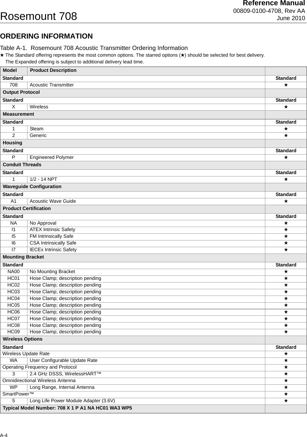
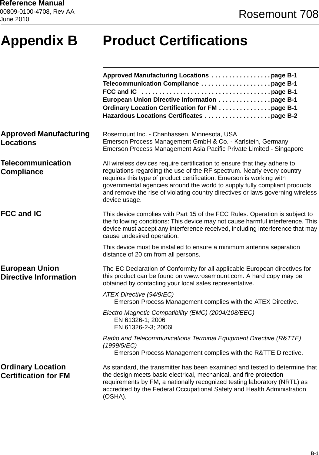
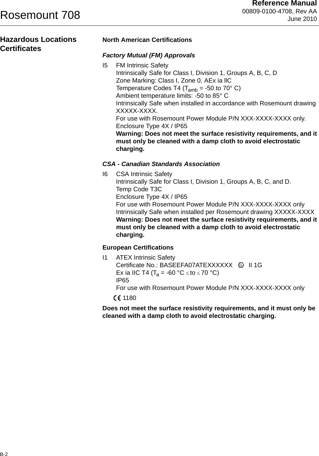
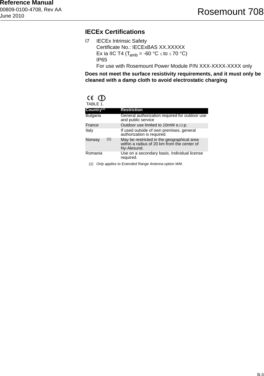
Rosemount RM708 Wireless HART Industrial Acoustical Transmitter User Manual

Rosemount Inc Wireless HART Industrial Acoustical Transmitter

User Manual

www.rosemount.comReference Manual 00809-0100-4708, Rev AAJune 2010Rosemount 708 Wireless Acoustic Transmitter
Reference Manual 00809-0100-4708, Rev AAJune 2010 Rosemount 708Rosemount 708 Wireless Acoustic TransmitterRosemount 708 Hardware RevisionHART® Device RevisionField Communicator Field Device Revision11Dev vX, DD vXNOTICERead this manual before working with the product. For personal and system safety, and for optimum product performance, make sure to thoroughly understand the contents before installing, using, or maintaining this product.The United States has two toll-free assistance numbers and one international number.Customer Central1 800 999 9307 (7:00 a.m. to 7:00 p.m. CST)National Response Center1 800 654 7768 (24 hours a day)Equipment service needsInternational1 952 906 8888The products described in this document are NOT designed for nuclear-qualified applications. Using non-nuclear qualified products in applications that require nuclear-qualified hardware or products may cause inaccurate readings. For information on Rosemount nuclear-qualified products, contact an Emerson Process Management Sales Representative.
Reference Manual00809-0100-4708, Rev AAJune 2010Rosemount 708The power module with the wireless unit contains one "D” size primary lithium/thionyl chloride batteries. Each battery contains approximately X.X grams of lithium.   Under normal conditions, the battery materials are self-contained and are not reactive as long as the batteries and the pack integrity are maintained. Care should be taken to prevent thermal, electrical or mechanical damage. Contacts should be protected to prevent premature discharge.Battery hazards remain when cells are discharged.Power modules should be stored in a clean and dry area. For maximum battery life, storage temperature should not exceed 30° C.The power module has surface resistivity greater than one gigaohm and must be properly installed in the wireless device enclosure. Care must be taken during transportation to and fromthe point of installation to prevent electrostatic charge build-up.Explosions could result in death or serious injury: Installation of this transmitter in an explosive environment must be in accordance with the appropriate local, national, and international standards, codes, and practices. Please review the approvals section of the 708 Reference Manual for any restrictions associated with a safe installation. • Before connecting a Field Communicator in an explosive atmosphere, ensure the instruments are installed in accordance with intrinsically safe or non-incendive field wiring practicesProcess leaks may cause harm or result in death: • Install and tighten process connectors before applying pressureElectrical shock can result in death or serious injury:• Avoid contact with the leads and terminals. High voltage that may be present on leads can cause electrical shockNOTICEThe Rosemount 708 and all other wireless devices should be installed only after the Smart Wireless Gateway has been installed and is functioning properly. Wireless devices should also be powered up in order of proximity from the Smart Wireless Gateway, beginning with the closest. This will result in a simpler and faster network installation.NOTICEShipping considerations for wireless products:The unit was shipped to you without the power module installed. Please remove the power module prior to shipping.Each power module contains one “D” size primary lithium battery. Primary lithium batteries are regulated in transportation by the U. S. Department of Transportation, and are also covered by IATA (International Air Transport Association), ICAO (International Civil Aviation Organization), and ARD (European Ground Transportation of Dangerous Goods). It is the responsibility of the shipper to ensure compliance with these or any other local requirements. Please consult current regulations and requirements before shipping.
Reference Manual 00809-0100-4708, Rev AAJune 2010TOC-1Rosemount 708SECTION 1Overview Safety Messages  . . . . . . . . . . . . . . . . . . . . . . . . . . . . . . . . . . . . . . . .  1-1Overview . . . . . . . . . . . . . . . . . . . . . . . . . . . . . . . . . . . . . . . . . . . . . . .  1-2Considerations . . . . . . . . . . . . . . . . . . . . . . . . . . . . . . . . . . . . . . . . . .  1-3Service Support  . . . . . . . . . . . . . . . . . . . . . . . . . . . . . . . . . . . . . . . . .  1-4Product Recycling/Disposal  . . . . . . . . . . . . . . . . . . . . . . . . . . . . . . . .  1-5SECTION 2Configuration Safety Messages  . . . . . . . . . . . . . . . . . . . . . . . . . . . . . . . . . . . . . . . .  2-1Device Sensor Configuration  . . . . . . . . . . . . . . . . . . . . . . . . . . . . . . .  2-1Device Network Configuration  . . . . . . . . . . . . . . . . . . . . . . . . . . . . . .  2-2Remove Power Module. . . . . . . . . . . . . . . . . . . . . . . . . . . . . . . . . . . .  2-5SECTION 3Mounting Safety Messages  . . . . . . . . . . . . . . . . . . . . . . . . . . . . . . . . . . . . . . . .  3-1Mounting . . . . . . . . . . . . . . . . . . . . . . . . . . . . . . . . . . . . . . . . . . . . . . .  3-2SECTION 4Commissioning Safety Messages  . . . . . . . . . . . . . . . . . . . . . . . . . . . . . . . . . . . . . . . .  4-1Verify Operation  . . . . . . . . . . . . . . . . . . . . . . . . . . . . . . . . . . . . . . . . .  4-2SECTION 5Operation and MaintenanceSafety Messages  . . . . . . . . . . . . . . . . . . . . . . . . . . . . . . . . . . . . . . . .  5-1Power Module Replacement. . . . . . . . . . . . . . . . . . . . . . . . . . . . . . . .  5-1APPENDIX ASpecifications and Reference DataSpecifications . . . . . . . . . . . . . . . . . . . . . . . . . . . . . . . . . . . . . . . . . . . A-1Dimensional Drawings  . . . . . . . . . . . . . . . . . . . . . . . . . . . . . . . . . . . . A-3Ordering Information . . . . . . . . . . . . . . . . . . . . . . . . . . . . . . . . . . . . . . A-4APPENDIX BProduct CertificationsTable of Contents
Reference Manual00809-0100-4708, Rev AAJune 2010Rosemount 708TOC-2
Reference Manual 00809-0100-4708, Rev AAJune 20101-1Rosemount 708Section 1 OverviewSafety Messages . . . . . . . . . . . . . . . . . . . . . . . . . . . . . . . . . page 1-1Overview  . . . . . . . . . . . . . . . . . . . . . . . . . . . . . . . . . . . . . . . page 1-2Considerations  . . . . . . . . . . . . . . . . . . . . . . . . . . . . . . . . . . page 1-3Service Support   . . . . . . . . . . . . . . . . . . . . . . . . . . . . . . . . . page 1-4Product Recycling/Disposal   . . . . . . . . . . . . . . . . . . . . . . . page 1-5SAFETY MESSAGES Instructions and procedures in this section may require special precautions to ensure the safety of the personnel performing the operations. Information that potentially raises safety issues is indicated by a warning symbol ( ). Please refer to the following safety messages before performing an operation preceded by this symbol.WarningsFailure to follow these installation guidelines could result in death or serious injury: • Only qualified personnel should perform the installationExplosions could result in death or serious injury.• Before connecting a Field Communicator in an explosive atmosphere, make sure that the instruments are installed in accordance with intrinsically safe or non-incendive field wiring practices• Verify that the operating atmosphere of the transmitter is consistent with the appropriate hazardous locations certificationsElectrical shock could cause death or serious injury.• Use extreme caution when making contact with the leads and terminals
Reference Manual00809-0100-4708, Rev AAJune 2010Rosemount 7081-2OVERVIEWManual This manual is designed to assist in the installation, operation, and maintenance of the Rosemount 702.Section 1: Overview• Overview• Considerations• Service Support• Product Recycling/DisposalSection 2: Configuration• Device Sensor Configuration• Device Network Configuration• Remove Power ModuleSection 3: Mounting• Mounting- Direct Mount• Ground the TransmitterSection 4: Commissioning• Verify Operation•AMS® Wireless ConfiguratorSection 5: Operation and Maintenance• Power Module ReplacementSection A: Specifications and Reference Data• Specifications• Dimensional Drawings• Ordering InformationSection B: Product Certifications• Approved Manufacturing Locations• Telecommunication Compliance• FCC and IC• European Union Directive Information• Ordinary Location Certification for FM• Hazardous Locations CertificatesTransmitter Features of the Rosemount 708 include:• An installation-ready solution that provides acoustic noise detection.• Acoustic levels to verify the state of steam traps, pressure relief valves, condensers, and many others.• Wireless output with >99% data reliability delivers rich HART® data, protected by industry leading security• Simple and easy installation practices currently being used for robust installations
Reference Manual 00809-0100-4708, Rev AAJune 20101-3Rosemount 708CONSIDERATIONSGeneral The acoustic transmitter detects either a noise or no noise along with a temperature.  By using simple HART configuration, the Rosemount 708 converts the noise and temperature status to a device status. Wireless Considerations Power Up SequenceThe power module should not be installed on any wireless device until the Smart Wireless Gateway (“Gateway”) is installed and functioning properly. Wireless devices should also be powered up in order of proximity from the Gateway, beginning with the closest. This will result in a simpler and faster network installation. Enable Active Advertising on the Gateway to ensure that new devices join the network faster. For more information see the Smart Wireless Gateway Manual (Document Number 00809-0200-4420).Antenna PositionThe antenna is internal to the acoustic transmitter.  If best practices are followed, the antenna position will not matter in the wireless functionality. Field Communicator ConnectionsThe Power Module needs to be connected for the Field Communicator to interface with the 708.Figure 1-1. Mechanical LocationWhen choosing an installation location and position, take into account access to the transmitter.
Reference Manual00809-0100-4708, Rev AAJune 2010Rosemount 7081-4Electrical Power ModuleThe Rosemount 708 Wireless transmitter is self-powered. The included power module contains one “D” size primary lithium/thionyl chloride battery. Each battery contains approximately X.X grams of lithium. Under normal conditions, the battery materials are self-contained and are not reactive as long as the batteries and the power module are maintained. Care should be taken to prevent thermal, electrical, or mechanical damage. Contacts should be protected to prevent premature discharge.Use caution when handling the power module, it may be damaged if dropped from heights in excess of 20 feet (6.10 m).Environmental Verify that the operating atmosphere of the transmitter is consistent with the appropriate hazardous locations certifications.Temperature EffectsThe transmitter will operate within specifications for ambient temperatures between -40 and 185 °F (-40 and 85 °C). Heat from the process is transferred from the switch to the transmitter housing. If the expected process temperature is near or beyond specification limits, ...add recommendationTemperature LimitsSERVICE SUPPORT To expedite the return process outside of North America, contact your Emerson Process Management representative, Within the United States, call the Emerson Process Management Response Center toll-free number 1 800 654 7768. The center, which is available 24 hours a day, will assist you with any needed information or materials.The center will ask for product model and serial numbers, and will provide a Return Material Authorization (RMA) number. The center will also ask for the process material to which the product was last exposed.SHIPPING CONSIDERATIONS FOR WIRELESS PRODUCTS (LITHIUM BATTERIES):The unit was shipped with the Power Module not installed. Please remove the Power Module from the unit before shipping.Primary lithium batteries (charged or discharged) are regulated during transportation by the U.S. Department of Transportation. They are also Operating Limit Storage Limit-40 to 185 °F-40 to 85° C-40 to 185 °F-40 to 85 °CIndividuals who handle products exposed to a hazardous substance can avoid injury if they are informed of, and understand, the hazard. If the product being returned was exposed to a hazardous substance as defined by OSHA, a copy of the required Material Safety Data Sheet (MSDS) for each hazardous substance identified must be included with the returned goods.
Reference Manual 00809-0100-4708, Rev AAJune 20101-5Rosemount 708covered by IATA (International Air Transport Association), ICAO (International Civil Aviation Organization), and ARD (European Ground Transportation of Dangerous Goods). It is the responsibility of the shipper to ensure compliance with these or any other local requirements. Consult current regulations and requirements before shipping.PRODUCT RECYCLING/DISPOSAL Recycling of equipment and packaging should be taken into consideration and disposed of in accordance with local and national legislation/regulations.
Reference Manual00809-0100-4708, Rev AAJune 2010Rosemount 7081-6
Reference Manual00809-0100-4708, Rev AAJune 2010Rosemount 7081-7
Reference Manual00809-0100-4708, Rev AAJune 2010Rosemount 7081-8
Reference Manual 00809-0100-4708, Rev AAJune 20102-1Rosemount 708Section 2 ConfigurationSafety Messages . . . . . . . . . . . . . . . . . . . . . . . . . . . . . . . . . page 2-1Device Sensor Configuration   . . . . . . . . . . . . . . . . . . . . . . page 2-1Device Network Configuration   . . . . . . . . . . . . . . . . . . . . . page 2-2Remove Power Module   . . . . . . . . . . . . . . . . . . . . . . . . . . . page 2-5SAFETY MESSAGES Instructions and procedures in this section may require special precautions to ensure the safety of the personnel performing the operations. Information that potentially raises safety issues is indicated by a warning symbol ( ). Please refer to the following safety messages before performing an operation preceded by this symbol.WarningsDEVICE SENSOR CONFIGURATION Remove the power module housing then connect to the HART communication terminals for configuration. The Rosemount 708 will receive any HART communication from a handheld Field Communicator, or AMS®. When using a Field Communicator, any configuration changes must be sent to the transmitter using the Send key (F2). AMS configuration changes are implemented when the Apply button is clicked.AMS® Wireless ConfiguratorAMS is capable of connecting to devices directly, using a HART modem, or with the Gateway. When configuring on the bench with a HART modem, double click the device icon, then choose the Configure/Setup tab (or right click and select Configure/Setup). Configure the device settings using the Direct Connection menu. When configuring with the Gateway, double click the device icon then choose the Configure/Setup tab (or right click and select Configure/Setup). Configure the device settings using the Wireless Connection menu.To check or change sensor configuration using a 475 Field Communicator, enter the following Fast Key Sequence: X, X, X.Failure to follow these installation guidelines could result in death or serious injury: • Only qualified personnel should perform the installationExplosions could result in death or serious injury.• Before connecting a Field Communicator in an explosive atmosphere, make sure that the instruments are installed in accordance with intrinsically safe or non-incendive field wiring practices• Verify that the operating atmosphere of the transmitter is consistent with the appropriate hazardous locations certificationsElectrical shock could cause death or serious injury.• Use extreme caution when making contact with the leads and terminals
Reference Manual00809-0100-4708, Rev AAJune 2010Rosemount 7082-2DEVICE NETWORK CONFIGURATION To communicate with the Gateway, and ultimately the Information System, the transmitter must be configured to communicate with the wireless network. Using a Field Communicator or AMS, enter the Network ID and Join Key so they match the Network ID and Join Key of the Gateway and the other devices in the network. If the Network ID and Join Key are not identical, the transmitter will not communicate with the network. The Network ID and Join Key may be obtained from the Gateway on the Setup>Network>Settings page on the web server. Using a 475 Field Communicator, the Network ID can be configured by entering the Fast Key Sequence: X, X, X, X. The Join Key can also be configured using a 475 Field Communicator with the Fast Key Sequence: X, X, X, X.The final device network configuration piece is the Update Rate which, by default, is 1 minute. It can be changed at commissioning, or at any time, by using AMS or the Gateway’s web server. The Update Rate should be between 4 seconds and 60 minutes. To change the Update Rate with a Field Communicator, use the Fast Key Sequence: X, X, X.If doing a bench top initial configuration, after completion remove the power module until installation. When the device is installed, insert he power module and close the housing cover securely. Always ensure a proper seal so that polymer touches polymer, but do not over tighten.Figure 2-1. 708 Power ModuleConnect the HART communication leads to the COMM terminals on the power module.
Reference Manual 00809-0100-4708, Rev AAJune 20102-3Rosemount 708Figure 2-2. 475 Field Communicator ConnectionsFor HART communication, a 708 DD is required.
Reference Manual00809-0100-4708, Rev AAJune 2010Rosemount 7082-4HART Menu Tree For ease of operation, changing setup, such as switch type, can be completed in several locations.Figure 2-3. Field Communicator Menu Tree1.  Overview2.  Configure3.  Service Tools1.  Active Alerts2.  Communication Status3.  Sensor4.  Sensor Status5.  Last Update Time1.  Guided Setup2.  Manual Setup1.  Alerts2.  Variables3.  Communications4.  Routine Maintenance5.  Simulate1.  Join Device to Network 2.  Configure Update Rate3.  Configure Discrete Application4.  Configure Device Display1.  Wireless2.  Discrete Sensors3.  Electronics Temperature4.  Device Information5.  Device Display6.  Other1.  Active Alerts2.  History1.  Discrete Input 12.  Discrete Input 23.  Electronics Temperature4.  Electronics temperature Status5.  Supply Voltage6.  Supply Voltage Status7.  Last Update Time1.  Join Status2.  Communication Status3.  Join Mode4.  Number of Available Neighbors5.  Number of Advertisements Heard6.  Number of Join Attempts1.  Sensor Calibration2.  Other1.  Discrete Input 12.  Discrete Input 23.  Electronics Temperature4.  Supply Voltage1.  Clear Alert History1.  Discrete Input 1 Sensor Wiring Offset2.  Discrete Input 2 Sensor Wiring Offset1.  Perform Master Reset2.  Measurement History3.  Advertise to New Devices1.  Network ID2.  Join Device to Network Broadcast Rates3.  Configure Broadcast Power Level4.  Power Mode5.  Power Source1.  Configure Discrete Application2.  Discrete Input 13.  Discrete Input 21.  Electronics Temperature2.  Electronics Temperature Status3.  Unit4.  Maximum5.  Minimum1.  Tag2.  Long Tag3.  Device4.  Discrete Input 15.  Discrete Input 26.  Wireless1.  Mode1.  Write Protect2.  AC Power Filter3.  Measurement and Status Log1.  Configure Update Rate2.  Message 13.  Message 21.  Discrete State2.  Invert Option3.  Sensor Serial Number1.  Discrete State2.  Invert Option3.  Sensor Serial Number1.  Manufacturer2.  Model3.  Final Assembly Number4.  Universal5.  Field Device6.  Software7.  Hardware8.  Descriptor9.  Message10 Date11 Model Number I12 Model Number II13 Model Number III14 SI Unit Restriction15 Country16 Device ID1.  Sensor Serial Number1.  Sensor Serial Number1.  Manufacturer2.  Device Type3.  Device Revision4.  Software Revision5.  Hardware Revision
Reference Manual 00809-0100-4708, Rev AAJune 20102-5Rosemount 708Fast Key Sequence Table 2-1 lists the fast key sequence for common transmitter functions.NOTE:The fast key sequences assume that DD Dev v1, DD v4 is being used.Table 2-1.  702 Fast Key SequenceCalibrationREMOVE POWER MODULE After the sensor and network have been configured, remove the power module and replace the power module cover. The power module should be inserted only when the device is ready for commissioningFunction Key Sequence Menu ItemsDevice Information 2, 2, 5, 3 Manufacturer, Model, Final Assembly Number, Universal, Field Device, Software, Hardware Descriptor, Message, Date, Model Number, I, II, III, SI Unit Restriction, CountryGuided Setup 2, 1 Join Device to Network, Configure Update Rate, Configure Sensor, Calibrate Sensor, Configure Display, Configure Process AlarmsManual Setup 2, 2 Wireless, Process Sensor, Percent of Range, Device Temperature, Device Information, Device Configure, OtherWireless 2, 2, 1 Network ID, Join Device to Network, Configure Update Rate, Configure Broadcast Power Level, Power Mode, Power SourceDiscrete Input Configuration 3, 4, 1 Output Configuration, Discrete Input Configuration
Reference Manual00809-0100-4708, Rev AAJune 2010Rosemount 7082-6
Reference Manual 00809-0100-4708, Rev AAJune 20103-1Rosemount 708Section 3 MountingSafety Messages . . . . . . . . . . . . . . . . . . . . . . . . . . . . . . . . . page 3-1Mounting  . . . . . . . . . . . . . . . . . . . . . . . . . . . . . . . . . . . . . . . page 3-2Direct Mount  . . . . . . . . . . . . . . . . . . . . . . . . . . . . . . . . . . . . page 3-2Ground the Transmitter  . . . . . . . . . . . . . . . . . . . . . . . . . . . page 3-5SAFETY MESSAGES Instructions and procedures in this section may require special precautions to ensure the safety of the personnel performing the operations. Information that potentially raises safety issues is indicated by a warning symbol ( ). Please refer to the following safety messages before performing an operation preceded by this symbol.WarningsFailure to follow these installation guidelines could result in death or serious injury: • Only qualified personnel should perform the installationExplosions could result in death or serious injury.• Before connecting a Field Communicator in an explosive atmosphere, make sure that the instruments are installed in accordance with intrinsically safe or non-incendive field wiring practices• Verify that the operating atmosphere of the transmitter is consistent with the appropriate hazardous locations certificationsElectrical shock could cause death or serious injury.• Use extreme caution when making contact with the leads and terminalsThis device complies with Part 15 of the FCC Rules. Operation is subject to the following conditions: This device may not cause harmful interference. This device must accept any interference received, including interference that may cause undesired operation.This device must be installed to ensure a minimum antenna separation distance of 20 cm from all persons.
Reference Manual00809-0100-4708, Rev AAJune 2010Rosemount 7083-2MOUNTING The acoustic transmitter is connected directly to the piping that is being measured. Direct Mount1. Align the metal foot of the transmitter onto the pipe.  2. Secure the transmitter with the two provided clamps.  One should be on each side of the foot.  3. If commissioning the device, install the power module.  Mounting Considerations
Reference Manual 00809-0100-4708, Rev AAJune 20103-3Rosemount 708
Reference Manual00809-0100-4708, Rev AAJune 2010Rosemount 7083-4
Reference Manual 00809-0100-4708, Rev AAJune 20103-5Rosemount 708
Reference Manual00809-0100-4708, Rev AAJune 2010Rosemount 7083-6
Reference Manual 00809-0100-4708, Rev AAJune 20104-1Rosemount 708Section 4 CommissioningSafety Messages . . . . . . . . . . . . . . . . . . . . . . . . . . . . . . . . . page 4-1Warnings  . . . . . . . . . . . . . . . . . . . . . . . . . . . . . . . . . . . . . . . page 4-1Verify Operation  . . . . . . . . . . . . . . . . . . . . . . . . . . . . . . . . . page 4-2AMS Wireless Configurator  . . . . . . . . . . . . . . . . . . . . . . . . page 4-3SAFETY MESSAGES Instructions and procedures in this section may require special precautions to ensure the safety of the personnel performing the operations. Information that potentially raises safety issues is indicated by a warning symbol ( ). Please refer to the following safety messages before performing an operation preceded by this symbol.WarningsNOTEThe Rosemount 708 and all other wireless devices should be installed only after the Gateway has been installed and is functioning properly.Wireless devices should be powered up in order of proximity from the Gateway, beginning with the device closest to the Gateway. This will result in a simpler and faster network installation.Failure to follow these installation guidelines could result in death orserious injury. • Make sure only qualified personnel perform the installation.Explosions could result in death or serious injury. • Before connecting a Field Communicator in an explosive atmosphere, make sure the instruments are installed in accordance with intrinsically safe or non-incendive field wiring practices.• Verify that the operating atmosphere of the transmitter is consistent with the appropriate hazardous locations certifications.Electrical shock could cause death or serious injury. • Use extreme caution when making contact with the leads and terminals.
Reference Manual00809-0100-4708, Rev AAJune 2010Rosemount 7084-2VERIFY OPERATION Operation can be verified in three locations: at the device, by using the 475 Field Communicator, at the Smart Wireless Gateway’s integrated web interface or via AMS Wireless Configurator.TroubleshootingIf the device is not joined to the network after power up, verify the correct configuration of the Network ID and Join Key, and verify that Active Advertising has been enabled on the Gateway. The Network ID and Join Key in the device must match the Network ID and Join Key of the Gateway.Field CommunicatorA 708 DD is required for HART communication. For connecting with a Field Communicator, refer to Figure 2-2 on page 2-3.Smart Wireless GatewayIn the integrated web interface from the Gateway, navigate to the Explorer>Status page. This page shows whether the device has joined the network and if it is communicating properly. NOTE:The time to join the new device(s) to the network is dependent upon the number of devices being joined and the number of devices in the current network. For one device joining an existing network with multiple devices, it may take up to five minutes. While it may take up to 60 minutes for multiple new devices to join the existing network.NOTE:If the device joins the network and immediately has an alarm present, it is likely due to sensor configuration. Check the sensor configuration (see Fast Key Sequence on page 2-5).Function Key Sequence Menu ItemsCommunications 3,3 Join Status, Wireless Mode, Join Mode, Number of Available Neighbors, Number of Advertisements Heard, Number of Join Attempts
Reference Manual 00809-0100-4708, Rev AAJune 20104-3Rosemount 708Figure 4-1. Smart Wireless Gateway Network SettingsAMS Wireless Configurator When the device has joined the network, it will appear in the Device Manager as illustrated below.TroubleshootingIf the device is not joined to the network after power up, verify the correct configuration of the Network ID and Join Key, and verify that Active Advertising has been enabled on the Gateway. The Network ID and Join Key in the device must match the Network ID and Join Key of the Gateway.The Network ID and Join Key may be obtained from the Gateway on the Setup>Network>Settings page on the web interface (see Figure 4-1 on page 4-3). The Network ID and Join Key may be changed in the wireless device by using the following Fast Key sequence.Function Key Sequence Menu ItemsWireless 2,1,1 Join Device to Network
Reference Manual00809-0100-4708, Rev AAJune 2010Rosemount 7084-4
Reference Manual 00809-0100-4708, Rev AAJune 20105-1Rosemount 708Section  5 Operation and MaintenanceSafety Messages . . . . . . . . . . . . . . . . . . . . . . . . . . . . . . . . . page 5-1Power Module Replacement  . . . . . . . . . . . . . . . . . . . . . . . page 5-1SAFETY MESSAGES Instructions and procedures in this section may require special precautions to ensure the safety of the personnel performing the operations. Information that potentially raises safety issues is indicated by a warning symbol ( ). Please refer to the following safety messages before performing an operation preceded by this symbol.WarningsPOWER MODULE REPLACEMENT Expected power module life is eight years at reference conditions.(1)When the power module needs to be replaced, remove the power module cover and the power module (Part Number 00753-9220-0001) then replace the cover. Tighten to specification and verify operation.Handling ConsiderationsThe power module with the wireless unit contains one “D” size primary lithium/thionyl chloride battery. Each battery contains approximately 2.5 grams of lithium. Under normal conditions, the battery materials are self-contained and are not reactive as long as the batteries and the battery pack integrity are maintained. Care should be taken to prevent thermal, electrical or mechanical damage. Contacts should be protected to prevent premature discharge.Use caution when handling the power module, it may be damaged if dropped from heights in excess of 20 feet.Battery hazards remain when cells are discharged.Failure to follow these installation guidelines could result in death orserious injury. • Make sure only qualified personnel perform the installation.Explosions could result in death or serious injury. • Before connecting a Field Communicator in an explosive atmosphere, make sure the instruments are installed in accordance with intrinsically safe or non-incendive field wiring practices.• Verify that the operating atmosphere of the transmitter is consistent with the appropriate hazardous locations certifications.Electrical shock could cause death or serious injury. • Use extreme caution when making contact with the leads and terminals.(1) Reference conditions are 70° F (21° C), transmit rate of once per minute, and routing data for three additional network devices.
Reference Manual00809-0100-4708, Rev AAJune 2010Rosemount 7085-2Environmental ConsiderationsAs with any battery, local environmental rules and regulations should be consulted for proper management of spent batteries. If no specific requirements exist, recycling through a qualified recycler is encouraged. Consult the materials safety data sheet for battery specific information.Shipping ConsiderationsThe unit was shipped to you without the power module installed. Please remove the power module prior to shipping.Each power module contains one “D” size primary lithium batteries. Primary lithium batteries are regulated in transportation by the U.S. Department of Transportation, and are also covered by International Air Transport Association (IATA), International Civil Aviation Organization (ICAO), and European Ground Transportation of Dangerous Goods (ARD). It is the responsibility of the shipper to ensure compliance with these or any other local requirements. Please consult current regulations and requirements before shipping.
Reference Manual 00809-0100-4708, Rev AAJune 2010A-1Rosemount 708Appendix A Specifications and Reference DataSpecifications  . . . . . . . . . . . . . . . . . . . . . . . . . . . . . . . . . . . page A-1Dimensional Drawings  . . . . . . . . . . . . . . . . . . . . . . . . . . . . page A-3Ordering Information  . . . . . . . . . . . . . . . . . . . . . . . . . . . . . page A-4SPECIFICATIONSFunctional Specifications OutputWirelessHART™ acoustic, temperature states.Humidity Limits0 - 100% relative humidityTemperature Limits-40 °C to 85 °CTransmit RateUser selectable, 4, 8, 16, 32 seconds, or 1 to 60 min.Physical Specifications Electrical Connections/Power Module• Replaceable, non-rechargeable, Intrinsically Safe Lithium-Thionyl Chloride power module pack with PBT enclosure• Eight year power module life at reference conditions(1)Field Communicator ConnectionsCommunication TerminalsClips permanently fixed to power moduleMaterials of ConstructionEnclosureHousing• PBT/PCCover O-ring• Buna-NPower Module• PBT/PCAntenna• Integrated omnidirectional antenna(1) Reference conditions are 70 °F (21 °C), transmit rate of once per minute, and routing data for three additional network devices.
Reference Manual00809-0100-4708, Rev AAJune 2010Rosemount 708A-2Wave Guide• Machined 316L SSTMountingTransmitters are directly attached to piping using two hose clamps. Weight708 with power module 20 ounces708 without power module 15 ouncesEnclosure ratings (702)Housing option code P is NEMA 4X, and IP65.Performance Specifications Self CalibrationThe analog-to-digital measurement circuity automatically self-calibrates for each status update by comparing the dynamic measurement to extremely stable and accurate internal reference elements.Vibration EffectTested per the requirements of IEC60770-1 field or pipeline with high vibration level (10-60 Hz 0.21 mm displacement peak amplitude/60-2000 Hz 3g).
Reference Manual 00809-0100-4708, Rev AAJune 2010A-3Rosemount 708DIMENSIONAL DRAWINGS708 Direct MountDimensions are in inches (millimeters)
Reference Manual00809-0100-4708, Rev AAJune 2010Rosemount 708A-4ORDERING INFORMATIONTable A-1.  Rosemount 708 Acoustic Transmitter Ordering Information★ The Standard offering represents the most common options. The starred options (★) should be selected for best delivery.__The Expanded offering is subject to additional delivery lead time.Model Product DescriptionStandard Standard708 Acoustic Transmitter ★Output ProtocolStandard StandardX  Wireless ★MeasurementStandard Standard1Steam ★2Generic ★HousingStandard StandardPEngineered Polymer ★Conduit ThreadsStandard Standard11/2 - 14 NPT ★Waveguide ConfigurationStandard StandardA1 Acoustic Wave Guide ★Product CertificationStandard StandardNA No Approval ★I1 ATEX Intrinsic Safety ★I5 FM Intrinsically Safe ★I6 CSA Intrinsically Safe ★I7 IECEx Intrinsic Safety ★Mounting BracketStandard StandardNA00 No Mounting Bracket ★HC01 Hose Clamp; description pending ★HC02 Hose Clamp; description pending ★HC03 Hose Clamp; description pending ★HC04 Hose Clamp; description pending ★HC05 Hose Clamp; description pending ★HC06 Hose Clamp; description pending ★HC07 Hose Clamp; description pending ★HC08 Hose Clamp; description pending ★HC09 Hose Clamp; description pending ★Wireless OptionsStandard StandardWireless Update Rate ★WA User Configurable Update Rate ★Operating Frequency and Protocol ★32.4 GHz DSSS, WirelessHART™ ★Omnidirectional Wireless Antenna ★WP Long Range, Internal Antenna ★SmartPower™ ★5Long Life Power Module Adapter (3.6V) ★Typical Model Number: 708 X 1 P A1 NA HC01 WA3 WP5
Reference Manual 00809-0100-4708, Rev AAJune 2010B-1Rosemount 708Appendix B Product CertificationsApproved Manufacturing Locations  . . . . . . . . . . . . . . . . . page B-1Telecommunication Compliance . . . . . . . . . . . . . . . . . . . . page B-1FCC and IC   . . . . . . . . . . . . . . . . . . . . . . . . . . . . . . . . . . . . . page B-1European Union Directive Information . . . . . . . . . . . . . . . page B-1Ordinary Location Certification for FM . . . . . . . . . . . . . . . page B-1Hazardous Locations Certificates . . . . . . . . . . . . . . . . . . . page B-2Approved Manufacturing Locations Rosemount Inc. - Chanhassen, Minnesota, USAEmerson Process Management GmbH & Co. - Karlstein, GermanyEmerson Process Management Asia Pacific Private Limited - SingaporeTelecommunication Compliance All wireless devices require certification to ensure that they adhere to regulations regarding the use of the RF spectrum. Nearly every country requires this type of product certification. Emerson is working with governmental agencies around the world to supply fully compliant products and remove the rise of violating country directives or laws governing wireless device usage.FCC and IC This device complies with Part 15 of the FCC Rules. Operation is subject to the following conditions: This device may not cause harmful interference. This device must accept any interference received, including interference that may cause undesired operation.This device must be installed to ensure a minimum antenna separation distance of 20 cm from all persons.European Union Directive Information The EC Declaration of Conformity for all applicable European directives for this product can be found on www.rosemount.com. A hard copy may be obtained by contacting your local sales representative.ATEX Directive (94/9/EC)Emerson Process Management complies with the ATEX Directive.Electro Magnetic Compatibility (EMC) (2004/108/EEC)EN 61326-1; 2006EN 61326-2-3; 2006lRadio and Telecommunications Terminal Equipment Directive (R&TTE) (1999/5/EC)Emerson Process Management complies with the R&TTE Directive.Ordinary Location Certification for FM As standard, the transmitter has been examined and tested to determine that the design meets basic electrical, mechanical, and fire protection requirements by FM, a nationally recognized testing laboratory (NRTL) as accredited by the Federal Occupational Safety and Health Administration (OSHA).
Reference Manual00809-0100-4708, Rev AAJune 2010Rosemount 708B-2Hazardous Locations Certificates North American CertificationsFactory Mutual (FM) ApprovalsI5 FM Intrinsic SafetyIntrinsically Safe for Class I, Division 1, Groups A, B, C, DZone Marking: Class I, Zone 0, AEx ia llCTemperature Codes T4 (Tamb = -50 to 70° C)Ambient temperature limits: -50 to 85° CIntrinsically Safe when installed in accordance with Rosemount drawing XXXXX-XXXX.For use with Rosemount Power Module P/N XXX-XXXX-XXXX only.Enclosure Type 4X / IP65Warning: Does not meet the surface resistivity requirements, and it must only be cleaned with a damp cloth to avoid electrostatic charging.CSA - Canadian Standards AssociationI6 CSA Intrinsic SafetyIntrinsically Safe for Class I, Division 1, Groups A, B, C, and D.Temp Code T3CEnclosure Type 4X / IP65For use with Rosemount Power Module P/N XXX-XXXX-XXXX onlyIntrinsically Safe when installed per Rosemount drawing XXXXX-XXXXWarning: Does not meet the surface resistivity requirements, and it must only be cleaned with a damp cloth to avoid electrostatic charging.European CertificationsI1 ATEX Intrinsic SafetyCertificate No.: BASEEFA07ATEXXXXXX  II 1GEx ia IIC T4 (Ta = -60 °C to 70 °C) IP65For use with Rosemount Power Module P/N XXX-XXXX-XXXX only1180Does not meet the surface resistivity requirements, and it must only be cleaned with a damp cloth to avoid electrostatic charging.
Reference Manual 00809-0100-4708, Rev AAJune 2010B-3Rosemount 708IECEx CertificationsI7 IECEx Intrinsic SafetyCertificate No.: IECExBAS XX.XXXXXEx ia IIC T4 (Tamb = -60 °C to 70 °C) IP65For use with Rosemount Power Module P/N XXX-XXXX-XXXX onlyDoes not meet the surface resistivity requirements, and it must only be cleaned with a damp cloth to avoid electrostatic charging TABLE 1. Country(1)(1) Only applies to Extended Range Antenna option WM.RestrictionBulgaria General authorization required for outdoor use and public serviceFrance Outdoor use limited to 10mW e.i.r.p.Italy  If used outside of own premises, general authorization is required.Norway May be restricted in the geographical area within a radius of 20 km from the center of Ny-Alesund.Romania Use on a secondary basis. Individual license required.(1)
Reference Manual00809-0100-4708, Rev AAJune 2010Rosemount 708B-4Figure B-1. Rosemount 702 FM Intrinsically Safe Installation Drawing
Reference Manual 00809-0100-4708, Rev AAJune 2010B-5Rosemount 708Figure B-2. Rosemount 702 CSA Intrinsic Safety Installation Drawing
Reference Manual00809-0100-4708, Rev AAJune 2010Rosemount 708B-6
00809-0100-4708 Rev AA. 6/10The Emerson logo is a trade mark and service mark of Emerson Electric Co.Rosemount and the Rosemount logotype are registered trademarks of Rosemount Inc. PlantWeb is a registered trademark of one of the Emerson Process Management group of companies.HART is a registered trademark of the HART Communication Foundation.Lexan and Noryl are registered trademark of General Electric.All other marks are the property of their respective owners.Standard Terms and Conditions of Sale can be found at www.rosemount.com/terms_of_sale© 2010 Rosemount Inc. All rights reserved.Reference Manual00809-0100-4708, Rev AAJune 2010Emerson Process Management Asia Pacific Private Limited1 Pandan CrescentSingapore 128461T (65) 6777 8211F (65) 6777 0947AP.RMT-Specialist@emersonprocess.comEmerson Process ManagementRosemount Inc.8200 Market BoulevardChanhassen, MN 55317 USAT (U.S.) 1 800 999 9307T (International) 952 906 8888F 952 949 7001www.rosemount.comRosemount Temperature GmbHFrankenstrasse 2163791 KarlsteinGermanyT 49 6188 992 0F 49 6188 992 112

Navigation menu