Rosslare 10F302 ProximityCard Reader used for Access Control User Manual OPSERI 1
Rosslare Enterprises Ltd ProximityCard Reader used for Access Control OPSERI 1
Rosslare >
Exhibit D Users Manual per 2 1033 b3
K5336 Rev. 6, 07/2001
-1-
OmniProx™ Reader
Model Series OP10/20/30/40/45/90
Installation Instructions
WHAT IS THE ADEMCO OmniProx™ READER?
The OmniProx Reader is an RFID proximity card
reader to be installed for use with access control
systems.
These installation instructions contain the following
information:
• Mounting Instructions
• Connecting the reader to the host
• Testing and operation of the reader
Visit www.omniprox.com for the latest information and
technical support.
HOW TO MOUNT THE READER
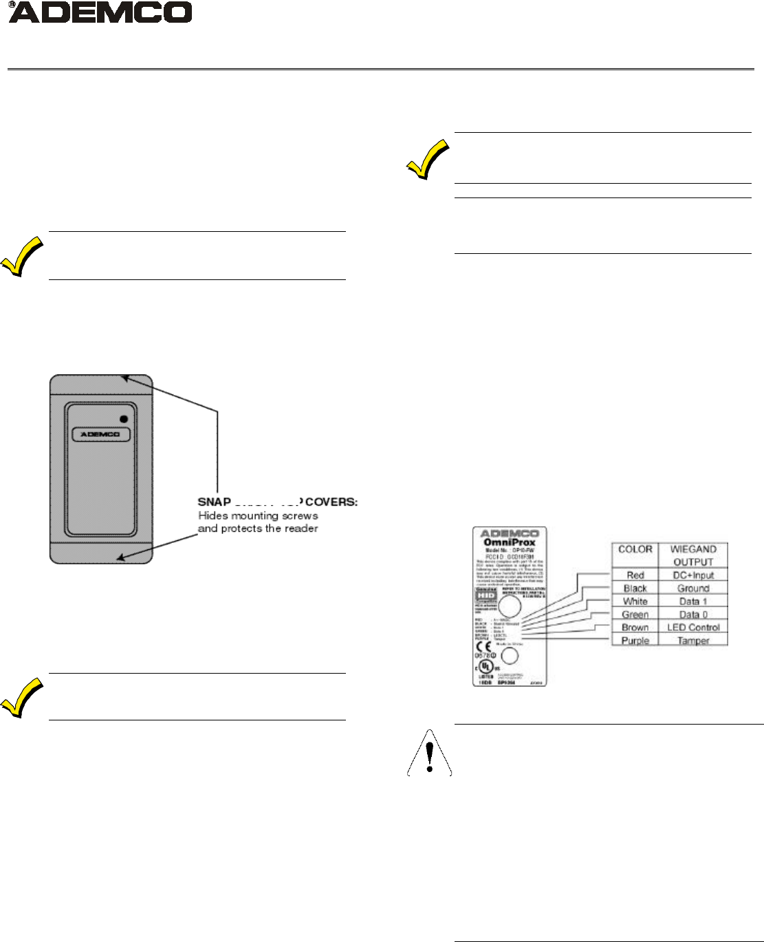
Figure 1 shows the front view of the OmniProx.
When mounting models OP10/20/30/40/45, the
snap-off cover must be removed to access the screw
holes.
The model OP90 uses a security screw on the
bottom of the reader to secure the cover. Remove
this security screw using the supplied tool. Then
slide the back plate down slightly and then lift it up
from the bottom. Select the desired mounting holes
and drill them out.
Mount the reader with the appropriate screws (not
supplied) as indicated on the template.
To surface mount the reader, perform the following:
1. Determine an appropriate mounting position
for the reader.
2. Peel off the back of the self-stick mounting label
template included with the unit and place at
the desired mounting position. (Additional
templates can be downloaded from
www.omniprox.com.)
3. Using the template as a guide, drill two holes
(hole size is indicated on mounting template) for
mounting the reader to the surface.
4. Drill a 1/2” (13 mm) hole for the cable. If
mounting on metal, place a grommet or
electrical tape around the edge of the hole.
5. Route the interface cable from the reader and/or
power supply to the host. A linear type power
supply is recommended.
Check all electrical codes for proper installation.
UL
Card Reader Models OP10/20/30/40/45/90 are to be
used with control panels whose power supply is UL
listed Class 2 or equivalent.
HOW TO CONNECT THE READER TO THE HOST
The OmniProx Reader is supplied with an 18-inch
pigtail, having a 6-conductor cable. To connect the
reader to the host, perform the following steps:
1. Prepare both the reader cable and host cables
by cutting the cable jacket back 1¼ inches and
strip the wires ½ inch.
2. Splice the reader pigtail wires to the
corresponding host wires and cover each
connection (see Figure 2).
3. If the tamper output is being utilized, connect
the purple wire to the correct input on the host.
4. Trim and cover all conductors that are not used.
Figure 2 below shows how you should wire the
reader to the host.
Wiring Notes:
1.
The individual wires coming out of the reader are color
coded according to the recommended Wiegand standard.
2.
If either 5 or 12 volts are available, use 12 volts for better
performance.
3. When using a separate power suppl
y for the reader, the
reader, power supply and host must have a common
ground.
4.
The recommended cable depends on the distance from the
reader to the host. See Table 1 on the next page for the
correct wire gage based upon distance. Larger wire
gauges are acc
eptable. The wire must be stranded with an
overall shield, either foil or braided. If the tamper is not
being used, 5 conductor cable is required; otherwise 6
Figure 2
Figure

-2-
conductor cable is required.
5.
The cable shield wire on the reader should be attached to
an Earth g
round (best) or signal ground connection at the
panel or power supply end of the cable. This configuration
is best for shielding the reader cable from external
interference.
TABLE 1: WIRE GAGE SPECIFICATIONS
Distance Gage
5 Conductor 6 Conductor
200 ft. (61m) 22 Alpha 1295C Alpha 1296C
300 ft. (91m) 20 Alpha 58126 Alpha 58126
500 ft. (153 m) 18 Alpha 58136 Alpha 58136
Note: Recommended cable is only a guideline, use any
manufacturer that meets the gage and shield specifications.
HOW TO TEST AND OPERATE THE READER
The reader should be tested after wiring it to a
power supply and the host. Do this by performing
the following steps:
1. Power up the reader. The LED and beeper will
activate three times. This indicates that the
reader is working properly.
2. Present the appropriate type of ID card to the
reader. (See Table 2 for the correct card type
based on the reader model.) The LED will
momentarily flash green and a short beep will
be emitted. This indicates that the card was
read properly by OmniProx.
3. After the card data is processed by the host, the
host can then turn the LED green or yellow.
Refer to the host description of the LED
operation if the reader LED is controlled by the
host.
Table 2: Model Number vs. Feature Matrix
Model
Number UL Listing
Part # Card
Type Output
Format Read
Range
(Max.) *
OP10-FW AY-K10 HID Wiegand 3”
OP10-AW
AY-K12 ADEMCO
Wiegand 3”
OP20-FW AY-J10 HID Wiegand 4”
OP20-AW
AY-J12 ADEMCO
Wiegand 4”
OP30-FW AY-L10 HID Wiegand 5”
OP30-AW
AY-L12 ADEMCO
Wiegand 5”
OP40-FW AY-H10 HID Wiegand 4”
OP40-AW
AY-H12 ADEMCO
Wiegand 4”
OP45-FW AY-M10 HID Wiegand 4”
OP45-AW
AY-M12 ADEMCO
Wiegand 4”
OP90-FW AY-Qxx HID Wiegand 1.5”
Model
Number UL Listing
Part # Card
Type Output
Format Read
Range
(Max.) *
TABLE 1: WIRE GAGE SPECIFICATIONS
Distance Gage
5 Conductor 6 Conductor
200 ft. (61m) 22 Alpha 1295C Alpha 1296C
300 ft. (91m) 20 Alpha 58126 Alpha 58126
500 ft. (153 m) 18 Alpha 58136 Alpha 58136
Note: Recommended cable is only a guideline, use any
manufacturer that meets the gage and shield specifications.
HOW TO TEST AND OPERATE THE READER
The reader should be tested after wiring it to a
power supply and the host. Do this by performing
the following steps:
1. Power up the reader. The LED and beeper will
activate three times. This indicates that the
reader is working properly.
2. Present the appropriate type of ID card to the
reader. (See Table 2 for the correct card type
based on the reader model.) The LED will
momentarily flash green and a short beep will
be emitted. This indicates that the card was
read properly by OmniProx.
3. After the card data is processed by the host, the
host can then turn the LED green or yellow.
Refer to the host description of the LED
operation if the reader LED is controlled by the
host.
Table 2: Model Number vs. Feature Matrix
Model
Number UL Listing
Part # Card
Type Output
Format Read
Range
(Max.) *
OP10-FW AY-K10 HID Wiegand 3”
OP10-AW
AY-K12 ADEMCO
Wiegand 3”
OP20-FW AY-J10 HID Wiegand 4”
OP20-AW
AY-J12 ADEMCO
Wiegand 4”
OP30-FW AY-L10 HID Wiegand 5”
OP30-AW
AY-L12 ADEMCO
Wiegand 5”
OP40-FW AY-H10 HID Wiegand 4”
OP40-AW
AY-H12 ADEMCO
Wiegand 4”

-3-
Model
Number UL Listing
Part # Card
Type Output
Format Read
Range
(Max.) *
OP45-FW AY-M10 HID Wiegand 4”
OP45-AW
AY-M12 ADEMCO
Wiegand 4”
OP90-FW AY-Qxx HID Wiegand 1.5”
*Measured using HID Corp. Prox Card II (P/N 1326LSSMV)
or equivalent and the corresponding OmniProx reader
powered at 12 volts. Range also depends on electrical
environment and/or proximity to metal.
SPECIFICATIONS
Electrical Characteristics:
Power Supply Type:
Linear type Recommended
Operating Voltage Range:
5.0 – 16 VDC (Operational down to 4.25 VDC)
Maximum input current:
OP10, OP20
Standby: 35 mA
Read: 50 mA
OP30, OP40, OP45, OP90
Standby: 35 mA
Read: 100 mA
Tamper Output
Open collector, active low, max.sink current is 16 mA
Maximum Cable Distance to Host:
500 ft. (150 meters)
Card Read Distance:
See Table 2
Regulatory Approvals:
USA: UL 294 Listed & FCC Part 15 B
(Model OP90 is not yet UL listed)
Europe: CE Listed
Operating Temperature Range:
-25° F to 145° F (-31°C to 63°C)
Operating Humidity:
0 to 95% (non condensing)
Suitable for outdoor use
Dimensions:
OP10:
3.15” (80mm) L x 1.58” (40mm) W x 0.50” (12.8mm) D
OP20:
4.73” (120mm) L x 1.65” (42mm) W x 0.55” (14mm) D
OP30:
5.71” (145mm) L x 1.69” (43mm) W x 0.79” (20mm) D
OP40:
4.33” (110mm) L x 2.96” (75mm) W x 0.59” (15mm) D
OP45:
3.5” (89mm) L x 3.5” (89mm) W x 0.59” (15mm) D
OP90:
4.72” (120mm) L x 3” (76mm) W x 1” (27mm) D
For additional information on th
e Wiegand™ Protocol, see
“Access Control Standard –
Wiegand Card Reader Interface
SIA AC-
01 (1996.10)” which can be purchased from SIA (see
www.siaonline.org)
OmniProx models with HID
compatibility are capable of reading
genuine HID cards under the ter
ms
of a license agreement between HID
Corp. and the ADEMCO Group.

-4-
FEDERAL COMMUNICATIONS COMMISSION (FCC) Part 15 STATEMENT
This equipment has been tested to FCC requirements and has been found acceptable for use. The FCC requires the following
statement for your information:
This equipment generates and uses radio frequency energy and if not installed and used properly, that is, in strict accordance with
the manufacturer's instructions, may cause interference to radio and television reception. It has been type tested and found to
comply with the limits for a Class B computing device in accordance with the specifications in Part 15 of FCC Rules, which are
designed to provide reasonable protection against such interference in a residential installation. However, there is no guarantee
that interference will not occur in a particular installation. If this equipment does cause interference to radio or television
reception, which can be determined by turning the equipment off and on, the user is encouraged to try to correct the interference
by one or more of the following measures:
• If using an indoor antenna, have a quality outdoor antenna installed.
• Reorient the receiving antenna until interference is reduced or eliminated.
• Move the radio or television receiver away from the receiver/control.
• Move the antenna leads away from any wire runs to the receiver/control.
• Plug the receiver/control into a different outlet so that it and the radio or television receiver are on different branch circuits.
If necessary, the user should consult the dealer or an experienced radio/television technician for additional suggestions. The user or
master may find the following booklet prepared by the Federal Communications Commission helpful:
"Interference Handbook"
This booklet is available from the U.S. Government Printing Office, Washington, DC 20402.
The user shall not make any changes or modifications to the equipment unless authorized by the Installation Instructions or User's
Manual. Unauthorized changes or modifications could void the user's authority to operate the equipment.
CE CERTIFICATION
DECLARATION OF CONFORMITY TO COUNCIL DIRECTIVE 89/336/EEC
Standards to which conformity is declared:
ETS 300 683, ETS 300 330 harmonized standard, low power emitters
EN 50130-4:1998 Product family standard: Immunity requirements for components of fire, intruder and social alarm systems
Issued by: ADEMCO, 165 Eileen Way, Syosset NY 11791
Tel: (516) 921-6704
www.ademco.com
Date of issue: 4-January-2001
Equipment type: Access Control Proximity Reader
Model numbers OP10, OP20, OP30, OP40, OP45, OP90
Acknowledgements:
OmniProx is a registered trademark of Pittway Corp.
Wiegand is a licensed trademark of HID Corp.
HID is a licensed trademark of HID Corp.
File No.
BP9264

-5-
ADEMCO Limited Warranty
Alarm Device Manufacturing Company, a Division of Pittway Corporation, and its divisions, subsidiaries and affiliates ("Seller"), 165
Eileen Way, Syosset, New York 11791, warrants OmniProx products to be in conformance with its own plans and specifications and
to be free from defects in materials and workmanship under normal use and service for the life of the product. Seller's obligation
shall be limited to repairing or replacing, at its option, free of charge for materials or labor, any product which is proved not in
compliance with Seller's specifications or proves defective in materials or workmanship under normal use and service. Seller shall
have no obligation under this Limited Warranty or otherwise if the product is altered or improperly repaired or serviced by anyone
other than Ademco factory service. For warranty service, return product transportation prepaid, to Ademco Factory Service, 165
Eileen Way, Syosset, New York 11791.
THERE ARE NO WARRANTIES, EXPRESS OR IMPLIED, OF MERCHANTABILITY, OR FITNESS FOR A PARTICULAR
PURPOSE OR OTHERWISE, WHICH EXTEND BEYOND THE DESCRIPTION ON THE FACE HEREOF. IN NO CASE SHALL
SELLER BE LIABLE TO ANYONE FOR ANY CONSEQUENTIAL OR INCIDENTAL DAMAGES FOR BREACH OF THIS OR ANY
OTHER WARRANTY, EXPRESS OR IMPLIED, OR UPON ANY OTHER BASIS OF LIABILITY WHATSOEVER, EVEN IF THE
LOSS OR DAMAGE IS CAUSED BY THE SELLER'S OWN NEGLIGENCE OR FAULT.
Seller does not represent that the products it sells may not be compromised or circumvented; that the products will prevent any
personal injury or property loss by burglary, robbery, fire or otherwise; or that the products will in all cases provide adequate
warning or protection. Customer understands that a properly installed and maintained alarm may only reduce the risk of a
burglary, robbery, fire or other events occurring without providing an alarm, but it is not insurance or a guarantee that such will not
occur or that there will be no personal injury or property loss as a result. CONSEQUENTLY, SELLER SHALL HAVE NO
LIABILITY FOR ANY PERSONAL INJURY, PROPERTY DAMAGE OR OTHER LOSS BASED ON A CLAIM THE PRODUCT
FAILED TO GIVE WARNING. However, if Seller is held liable, whether directly or indirectly, for any loss or damage arising under
this Limited Warranty or otherwise, regardless of cause or origin, Seller's maximum liability shall not in any case exceed the
purchase price of the product, which shall be the complete and exclusive remedy against Seller. This warranty replaces any
previous warranties and is the only warranty made by Seller on this product. No increase or alteration, written or verbal, of the
obligations of this Limited Warranty is authorized.
0706
-
0680001
-
02 / 9J
-ADM-
001
-B