Rosslare 30A303 Proximity and Keypad Reader User Manual AYC G64 Instruction Manual 130305
Rosslare Enterprises Ltd Proximity and Keypad Reader AYC G64 Instruction Manual 130305
Rosslare >
Contents
- 1. Users Manual F64
- 2. Users Manual G64
- 3. Users Manual Q64
Users Manual G64
AYC-G64
PROXIMITY CARD &
BACKLIT KEYPAD READER
WIEGAND AND CLOCK & DATA
INSTRUCTION MANUAL
06/04
www.rosslaresecurity.com
0706-0960039-00
FCC part 15 statement and warnings
NOTE: This equipment has been tested and found to comply with
the limits for a Class B digital device, pursuant to Part 15 of the
FCC Rules. These limits are designed to provide reasonable
protection against harmful interference in a residential installation.
This equipment generates uses and can radiate radio frequency
energy and, if not installed and used in accordance with the
instructions, may cause harmful interference to radio
communications. However, there is no guarantee that interference
will not occur in a particular installation. If this equipment does
cause harmful interference to radio or television reception, which
can be determined by turning the equipment off and on, the user is
encouraged to try to correct the interference by one or more of the
following measures:
-- Reorient or relocate the receiving antenna.
-- Increase the separation between the equipment and receiver.
-- Connect the equipment into an outlet on a circuit different from
that to which the receiver is connected.
-- Consult the dealer or an experienced radio/TV technician for
help.
Warning!
Changes or modifications to this equipment not expressly approved
by Rosslare Enterprises Ltd. could void the user’s authority to
operate the equipment.
Warning!
This product was tested with shielded cables, which must be used
with the unit to insure compliance.

Page 3 06/04
Introduction
Equipment provided
The following is provided as part of every AYC-G64 package:
The AYC-G64 is a waterproof programmable Wiegand and Clock &
Data proximity card and keypad reader. The AYC-G64 supports
multiple Proximity Card and Keypad formats providing a high level
of compatibility and connectivity with host controllers.
The unit can be programmed to output proximity card data in 26-Bit
Wiegand, Clock & Data or Wiegand Card + PIN format.
The backlit keypad can also be programmed to output eight
different data formats.
The AYC-G64 utilizes flash firmware for easy upgrades.
- AYC-G64 Access Control Unit.
- Installation Kit
- Installation and Operating Instructions
Additional Equipment Required
1) Compatible Host Controller
2) Power Supply
5 to 16V DC (From a Regulated Power Supply)
Other Rosslare accessories can be found at Rosslare's
Web Site:
http://www.rosslaresecurity.com
AYC-G64
Page 2 06/04
Contents
INTRODUCTION 3
Technical Specifications 4
Key Features 5
INSTALLATION 6
Mounting the AYC-G64 reader 6
Wiring the AYC-G64 reader 7
FEATURES AND CONCEPTS
Transmit Mode 8
PROGRAMMING THE AYC-G64 9
Entering Programming Mode 10
Exiting Programming Mode Operation 10
1 Setting Keypad Transmission Format 11
2 Setting Proximity Card Transmission Format 17
3 Changing the Programming Code 19
4 Changing the Facility Codes 20
0 Return to Factory Default Settings 20
Replacing a lost Programming Code 21
WARRANTY 22
TECHNICAL SUPPORT 24
AYC-G64

Page 5 06/04
Environmental Characteristics
Operating Temperature:
-22 F to 150 F (-30 C to 65 C)
Operating Humidity:
0 to 95% (Non-Condensing)
Suitable for outdoor use. (IP 65)
Mechanical Characteristics
Dimensions:
5.39" (137mm) L x 1.73" (44mm) W x 1.14" (29mm) D
Weight:
0.35 lbs (160g)
Built-In Proximity Card Reader (125 KHz ASK Modulation)
Programmable Proximity Card Transmission Format
1) Clock & Data
2) 26-Bit Wiegand
3) Wiegand Card + PIN
Built-In Backlit Keypad for PIN code entry
Programmable Keypad Transmission Format
Built-In Case and Back Tamper
Tamper Output & LED Control Input
Programmable Facility Code
Two Tri-Colored LEDs
Internal Buzzer provides audible interface feedback.
Comes with mounting template for easier installation.
Comes with Installation Kit that includes a security screw
And a security screw tool.
Key Features
Here are some of the AYC-G64's key features:
AYC-G64
06/04
Technical Specification
Electrical Characteristics
Operating Voltage Range:
5 to 16V DC From a Regulated Power Supply
(Linear type recommended)
Maximum Input Current:
Standby: 85mA Not including attached devices
Max: 95mA Not including attached devices
Built-In Proximity Reader
Read Range* 3.0" (80mm)
Modulation Options:
1) 26-Bit Wiegand, ASK at 125KHz
2) Clock & Data, ASK at 125KHz
Compatible Cards All 26-Bit EM Cards
Built-In Keypad Reader
Transmission Formats:
1) Single Key, 6-Bit Wiegand (Rosslare Format)
2) Single Key, 6-Bit Wiegand with Nibble and Parity Bits
3) Single Key, 8-Bit Wiegand, Nibbles Complemented
4) 4 Keys Binary + Facility Code, 26-Bit Wiegand
5) 1 to 5 Keys + Facility Code, 26-Bit Wiegand
6) 6 Keys BCD and Parity Bits, 26-Bit Wiegand
7) Single Key, 3x4 Matrix Keypad
8) 1 to 8 Keys BCD, Clock & Data
LED Control Input
Dry Contact, N.O.
Tamper Output
Open Collector, active low, maximum sink current is 32mA
*Measured using Rosslare Proximity Card (AT-14) or equivalent.
Range also depends on electrical environment and proximity to
metal.
Page 4
AYC-G64
Page 6 06/04
Installation
Mounting the AYC-G64 Controller
1) Before starting, select the location to mount the AYC-G64 reader.
This location should be at shoulder height.
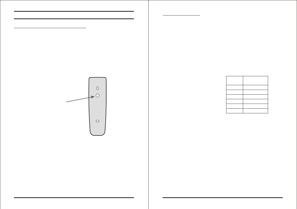
2) For wall mounting use the mounting template as a guide to drill
the mounting and cable holes in the wall. For US Gang Box
installation there are two hole indicators on the back of the metal
cover specifically aligned for the US Gang Box. (Shown marked
as "A" in diagram below).
3) Route the interface cable from the Reader to the Controller. A
linear type power supply is recommended.
4) Screw the AYC-G64 back cover to its mounting location.
5) Return the front cover of the AYC-G64 to the mounted back plate.
6) Secure the front cover by using the supplied security screw in the
controllers Installation Kit. An L-Shaped tool is provided for use
when tightening the security screw.
AYC-G64 Page 7 06/04
Wiring the AYC-G64
The reader is supplied with a 16-inch pigtail, having a 6-conductor
cable. To connect the reader to the Controller, perform the following
steps.
1) Prepare the reader cable by cutting the cable jacket back 1
inches and strip the wire inch. Prepare the controller cable by
cutting the cable jacket back 1 inches and strip the wire
inch.
2) Splice the reader pigtail wires to the corresponding controller
wires and cover each connection.
Table shows how you
should wire the Reader
to the controller.
3) If the tamper output is being utilized, connect the purple wire to
the correct input on the controller.
4) Trim and cover all conductors that are not used.
AYC-G64
Red
Black
White
Green
Brown
Purple
+V DC
Ground
Data 1 / Clock
Data 0 / Data
LED Control
Tamper
COLOR OUTPUT
14
/
12
/
14
/
12
/
Tamper
Lens
A
A
Page 9 06/04
AYC-G64
Transmit Mode
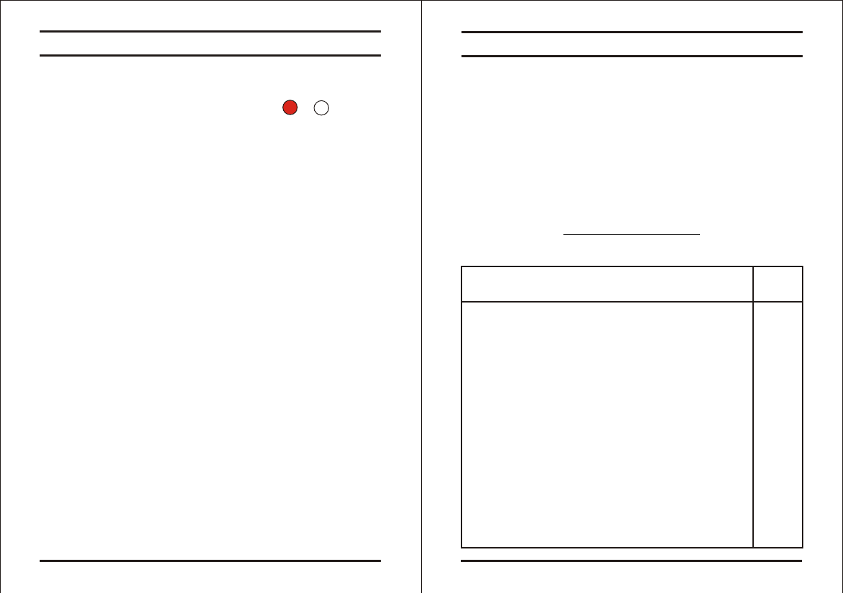
When the AYC-G64 is in Transmit Mode, it is ready to receive
data from a presented Proximity Card or an entered PIN code.
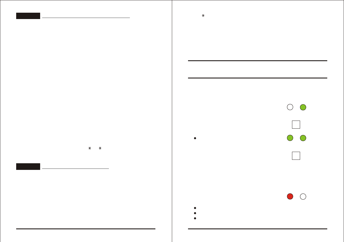
When the reader is in Transmit
Mode, the Transmit LED is red
and the Program LED is off
When a Proximity Card or Keyboard entry is being transmitted,
the Transmit LED will flash green.
Keyboard data can be sent via one of eight different Keypad
Transmission Formats. (Refer to page 11 for more information on
Selecting Keypad Transmission Formats")
Proximity Cards presented to the reader are always sent in either
26-Bit Wiegand, Clock & Dat or, Card + PIN Wiegand format.
(Refer to page 17 for more information on "Selecting Proximity
Card Transmission Formats")
Page 8 06/04
AYC-G64
Transmit Program
RED
Programming the AY-Q64
Programming the AYC-G64 is done solely via the unit's keypad
driven Programming Menu System. To reach the Programming
Menu System the AYC-G64 must first be placed into Programming
Mode. See "Entering Programming Mode" on the next page for
more information.
During the AYC-G64's manufacturing process certain codes and
settings are pre-programmed. These settings are the called the
"Default Factory Settings".
The table below shows the names of all the AYC-G64 Menus.
Programming Menu
Default Factory Settings are marked by a " " sign.
Selecting Keypad Transmission Format 1
1) Single Key, 6-Bit Wiegand (Rosslare Format)
2) Single Key, 6-Bit Wiegand with Nibble + Parity Bits
3) Single Key, 8-Bit Wiegand, Nibbles Complemented
4) 4 Keys Binary + Facility Code, 26-Bit Wiegand
5) 1 to 5 Keys + Facility Code, 26-Bit Wiegand
6) 6 Keys BCD and Parity Bits, 26-Bit Wiegand
7) Single Key, 3x4 Matrix Keypad
8) 1 to 8 Keys BCD, Clock & Data Single Key,
Selecting Proximity Card Transmission Format 2
1) 26-Bit Wiegand
2) Clock & Data
3) Wiegand Card + PIN
Changing the Programming Code 3
Changing the Facility Code 4
Return to Factory Default Settings 0
Menu Description Menu
Number
*
*
*
Page 10 06/04
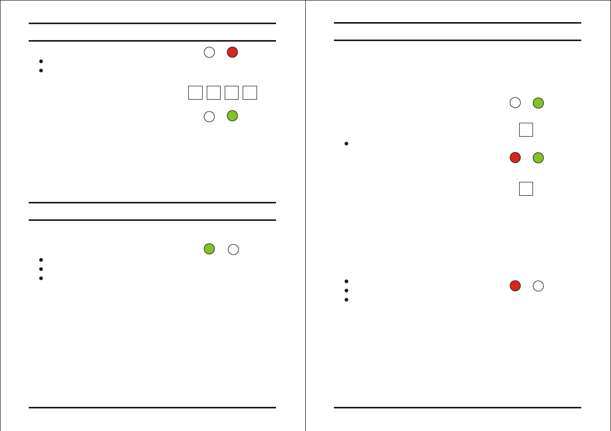
Entering Programming Mode
Exiting Programming Mode
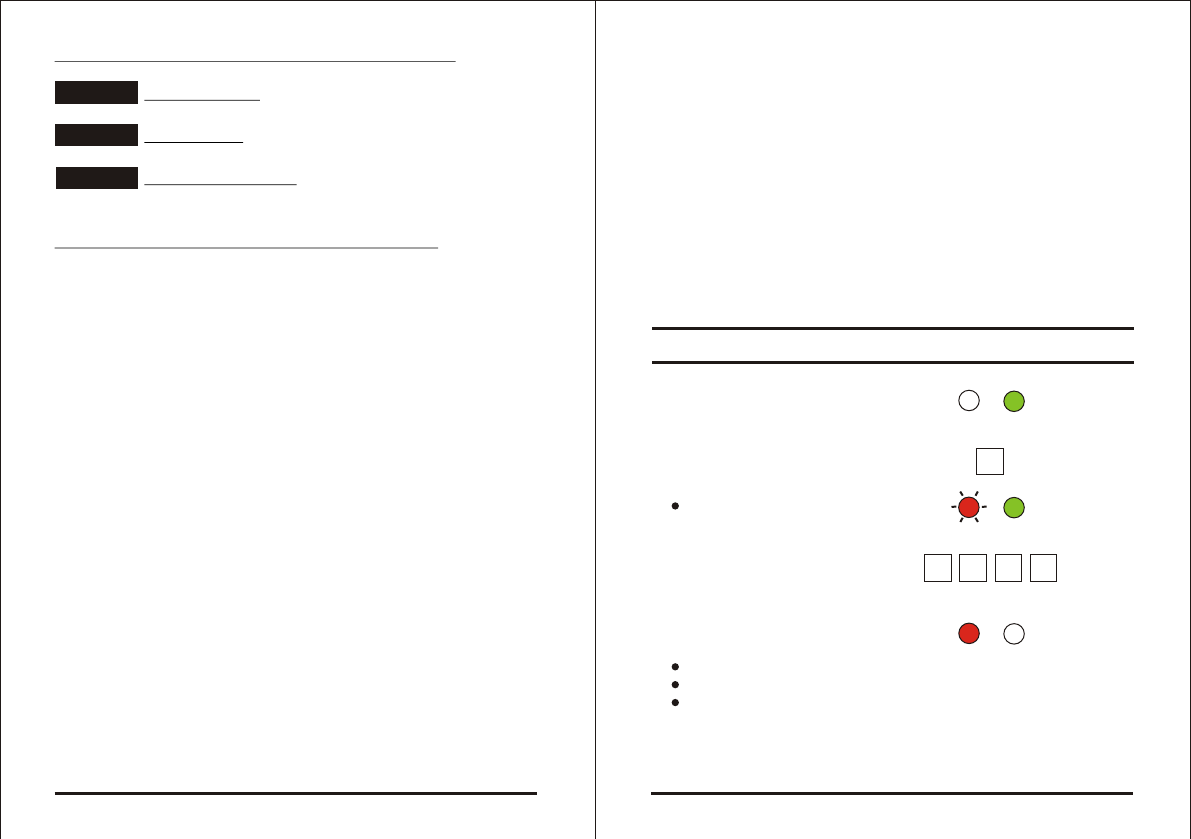
1) Press the "#" key 4 times.
Transmit LED will turn off
Program LED will turn red
2) Enter your 4-digit Programming
Code.
If the Programming Code
is valid the Program LED will turn
green and the AYC-G64 will be in
Programming Mode.
Note: - The factory default Programming Code is 1234
- If a Programming Code is not entered within 30
seconds, the AYC-G64 will return to Transmit Mode.
1) To exit the Programming Mode at any time:
Press the "#" key.
You will hear a beep
The Program LED will be off
The Transmit LED will turn green
This indicates that the AYC-G64 has returned to Transmit Mode.
2) Wrong entries may reset the reader back to Transmit Mode.
3) While in Programming Mode if no key is pressed for 30 seconds
the AYC-G64 will exit Programming Mode and return to Transmit
Mode.
AYC-G64
Transmit Program
Transmit Program
GREEN
RED
1 2 34
Transmit Program
GREEN
Selecting Keypad Transmission Format
The AYC-G64 has eight different keypad transmission formats to
select from. Follow the steps below to select the appropriate keypad
transmission format that you wish to use.
1) Enter Programming Mode
2) Press "1" to enter Menu 1
The Transmit LED will turn red
3) Enter the appropriate option number
for the keypad transmission format
that you wish to select.
If an incorrect option number is entered the reader will return to
Transmit Mode and the keypad transmission format will remain
unchanged
Look on the next page for more information on the keypad
transmission formats.
4) System returns to Transmit Mode
You will hear one beep
The Program LED will turn off
The Transmit LED will turn red
Note: - Only one keypad transmission format can be active at
any one time.
- When using the keypad transmission format "1 to 8 keys
BCD, Clock & Data" (Option 8) an additional input is
required to specify the number of keys in the PIN code.
Page 11 06/04
AYC-G64
Transmit Program
GREEN
1
?
Transmit Program
GREENRED
Transmit Program
RED
AYC-G64
Single Key, 6-Bit Wiegand, Nibble & Parities
Each key press immediately sends 4 bits with 2 parity bits added.
Even parity for the first 3 bits and odd parity for the last 3 bits.
0 = 0 0000 1 6 = 1 0110 0
1 = 0 0001 0 7 = 1 0111 1
2 = 0 0010 0 8 = 1 1000 1
3 = 0 0011 1 9 = 1 1001 0
4 = 1 0100 1 = 1 1010 0 = "B" in Hexadecimal
5 = 1 0101 0 # = 1 1011 1 = "C" in Hexadecimal
Single Key, 8-Bit Wiegand, Nibbles Complemented
Inverts the most significant bits in the message leaving the least 4
significant bits as Binary-Coded Decimal (BCD) representation of
the key. The host system receives an 8-bit message.
0 = 11110000 6 = 10010110
1 = 11100001 7 = 10000111
2 = 11010010 8 = 01111000
3 = 11000011 9 = 01101001
4 = 10110100 = 01011010 = "A" in Hexadecimal
5 = 10100101 # = 01001011 = "B" in Hexadecimal
4 Keys Binary + Facility Code, 26-Bit Wiegand
Buffers 4 keys and outputs keypad data with a three digit facility
code like a standard 26-Bit card output.
The facility code is set in Programming Menu number four and can
be in the range 000 to 255. The factory default setting for the facility
code is 000. (See page 20 for more information on "Changing the
Facility Code")
Page 13 06/04
AYC-G64
OPTION 2
OPTION 3
OPTION 4
Keypad Transmission Format Option Number
See the table below to determine the Option Number for the
Keypad Transmission Format you wish to select.
Single Key, 6-Bit Wiegand (Rosslare Format) 1*
Single Key, 6-Bit Wiegand with Nibble + Parity Bits 2
Single Key, 8-Bit Wiegand, Nibbles Complemented 3
4 Keys Binary + Facility Code, 26-Bit Wiegand 4
1 to 5 Keys + Facility Code, 26-Bit Wiegand 5
6 Keys BCD and Parity Bits, 26-Bit Wiegand 6
Single Key, 3x4 Matrix Keypad 7
1 to 8 Keys BCD, Clock & Data Single Key, 8
* Option 1 is the default factory setting.
More information on each of the different keypad transmission
formats is available below and on the following pages.
Single Key, 6-Bit Wiegand (Rosslare Format)
Each key press immediately sends 4 bits with 2 parity bits added.
Even parity for the first 3 bits and odd parity for the last 3 bits.
0 = 1 1010 0 6 = 1 0110 0
1 = 0 0001 0 7 = 1 0111 1
2 = 0 0010 0 8 = 1 1000 1
3 = 0 0011 1 9 = 1 1001 0
4 = 1 0100 1 = 1 1011 1 = "B" in Hexadecimal
5 = 1 0101 0 # = 0 1101 1 = "C" in Hexadecimal
Page 12 06/04
Keypad Transmission Format Option
Number
OPTION 1

The keypad PIN code must be 4 digits long and can range between
0001 and 9999. On the fourth key press of the 4 digit PIN code, the
data is sent across the Wiegand Data lines as binary data in the
same format as a 26-Bit Card.
If the " " key or the "#" key are pressed during PIN code entry, the
keypad will clear the PIN code entry buffer, generate a beep and is
ready to receive a new 4 digit keypad PIN code.
If the entry of the 4 digit keypad PIN code is disrupted and no
number key is pressed within 5 seconds, the keypad will clear the
PIN code entry buffer, generate a beep and is ready to receive a
new 4 digit keypad PIN code.
(EP) FFFF FFFF AAAA AAAA AAAA AAAA (OP)
Where: EP = Even parity for first 12 bits.
OP = Odd parity for last 12 bits.
F = 8-Bit Facility Code.
A = 24-Bit code generated from keyboard.
1 to 5 Keys + Facility Code, 26-Bit Wiegand
Buffers up to 5 keys and outputs keypad data with a facility code
like a 26-Bit card output.
The facility code is set in Programming Menu number four and can
be in the range 000 to 255. The factory default setting for the facility
code is 000. (See page 20 for more information on "Setting the
Facility Code")
The keypad PIN code can be one to five digits long and can range
between 1 and 65,535. When entering a keypad PIN code that is
less than 5 digits long, the "#" key must be pressed to signify the
end of PIN code entry. For keypad PIN codes that are 5 digits long,
on the fifth key press of the 5 digit PIN code, the data is sent across
the Wiegand Data lines as binary data in the same format as a 26-
Bit Card.
Page 14 06/04
AYC-G64
OPTION 5
If the " " key or the "#" key are pressed during PIN code entry or a
PIN code greater than 65,535 is entered, the keypad will clear the
PIN code entry buffer, generate a beep and is ready to receive a
new 4 digit keypad PIN code.
If the entry of the 1 to 5 digit keypad PIN code is disrupted and no
number key or "#" key is pressed within 5 seconds, the keypad will
clear the PIN code entry buffer, generate a medium length beep and
is ready to receive a new 1 to 5 digit keypad PIN code.
(EP) FFFF FFFF AAAA AAAA AAAA AAAA (OP)
Where: EP = Even parity for first 12 bits.
OP = Odd parity for last 12 bits.
F = 8-Bit Facility Code.
A = 24-Bit code generated from keyboard.
6 Keys BCD and parity bits, 26-Bit Wiegand
Sends buffer of 6 keys, adds parity and sends a 26-Bit Binary-
Coded Decimal (BCD) message. Each key is a four bit equivalent of
the decimal number.
The keypad PIN code must be 6 key presses long. On the sixth key
press of the 6 digit PIN code, the data is sent across the Wiegand
Data lines as a BCD message.
If the entry of the 6 digit keypad PIN code is disrupted and no
number key is pressed within 5 seconds, the keypad will clear the
PIN code entry buffer, generate a medium length beep and is ready
to receive a new 6 digit keypad PIN code.
(EP) AAAA BBBB CCCC DDDD EEEE FFFF (OP)
Where:
A = The first key entered. D = Fourth key entered.
B = Second key entered. E = Fifth key entered.
C = Third key entered. F = Sixth key entered.
Page 15 06/04
AYC-G64
OPTION 6
Single Key, 3x4 Matrix Keypad (MD-P64)
This unique mode is intended to let the host controller scan the
AYC-G64's keypad while still keeping the proximity card readers 26-
Bit Wiegand or Clock & Data formats active.
An optional interface board must be used between the AYC-G64
and the host system. Each key press is immediately sent on DATA0
as an ASCII character at a baud rate of 9600 bits per second.
When a key is pressed DATA1 is pulled "low" until the key is
released at which point DATA1 will be set to "high". This allows the
controller to detect the duration of the key press.
The MD-P64 interface unit outputs the data received to 7 outputs
emulating a keyboard. The interface unit will not effect any data that
it receives from the proximity reader wether it is 26-Bit Wiegand or
Clock & Data.
Key pressed = ASCII Value
0 = '0' ( 0x30 hex ) 6 = '6' ( 0x36 hex )
1 = '1' ( 0x31 hex ) 7 = '7' ( 0x37 hex )
2 = '2' ( 0x32 hex ) 8 = '8' ( 0x38 hex )
3 = '3' ( 0x33 hex ) 9 = '9' ( 0x39 hex )
4 = '4' ( 0x34 hex ) = ' ' ( 0x2A hex )
5 = '5' ( 0x35 hex ) # = '#' ( 0x23 hex )
1 to 8 Keys BCD, Clock & Data
Buffers up to 8 keys and outputs keypad data without a facility code
like standard Clock and Data card output.
The keypad PIN code can be one to eight digits long. The PIN code
length is selected while programming the reader for Option 8. The
reader will transmit the data when it receives the last key press of
the PIN code. The data is sent across the two data output lines as
binary data in Clock & Data format.
Page 16 06/04
AYC-G64
OPTION 7
OPTION 8
If the " " key or the "#" key are pressed during PIN code entry, the
keypad will clear the PIN code entry buffer, generate a beep and is
ready to receive a new keypad PIN code.
If the entry of the digit keypad PIN code is disrupted and no number
key or "#" key is pressed within 5 seconds, the keypad will clear the
PIN code entry buffer, generate a medium length beep and is ready
to receive a new keypad PIN code.
The AYC-G64 has two different proximity card transmission formats
to select from. Follow the steps below to select the appropriate
Proximity Card reader transmission format that you wish to use.
1) Enter Programming Mode
2) Press "2" to enter Menu 2
The Transmit LED will turn
green
3) Enter the appropriate option number
for the proximity card transmission format
that you wish to select. (See options below)
If an incorrect option number is entered the reader will return to
Transmit Mode and the keypad transmission format will remain
unchanged.
4) System returns to
Transmit Mode
You will hear one beep
The Program LED will turn off
The Transmit LED will turn red
Selecting Proximity Card
Transmission Format
Page 17 06/04
AYC-G64
Transmit Program
GREEN
2
?
Transmit Program
GREENGREEN
Transmit Program
RED
Proximity Card Transmission Format Option Number
26-Bit Wiegand
Clock & Data
Wiegand Card + PIN
Note : "Wiegand Card + PIN" Transmission Format
This unique mode is intended to let host controllers get card and
keypad data simultaneously. This option overrules the selected
Keypad Transmission Format and sends the keypad data as
described below.
After a card is presented to AYC-G64, the Program LED starts to
flash in Green and indicates that AYC-G64 is waiting for the PIN
code. If the entry of one to five digit keypad PIN code is disturbed
and no digit key or # key is pressed within 5 seconds, the keypad
will clear the card buffer and the PIN code entry buffer, generate a
medium length beep and ready to receive a new card.
The keypad PIN code can be one to five digits long in the range
between 0 to 99,999. When entering a keypad PIN code, the # key
must be pressed to signify the end of the PIN entry. When pressing the
# key press, the data is sent by the Wiegand data lines. If the * key is
pressed, the keypad will clear the card buffer and the PIN code entry
buffer, generate a medium length beep and is ready to receive a new
card.
AYC-G64 output card data in 26-Bit Wiegand with following keypad
data in 26-Bit Wiegand format.
Card Data : (EP) AAAA AAAA AAAA BBBB BBBB BBBB (OP)
where EP =Even parity for first 12 A bits.
OP =Odd parity for last B 12 bits.
Page 18 06/04
AYC-G64
OPTION 1
OPTION 2
OPTION 3
PIN Data : (EP) 0000 AAAA BBBB CCCC DDDD EEEE (OP)
where A =The first key entered. D =Fourth key entered.
B =Second key entered. E =Fifth key entered.
C =Third key entered.
EP =Even parity for first 12 bits.
OP =Odd parity for last 12 bits.
If the PIN code is less than 5 digits, all the most significant nibbles
are filled with 0.
Example : (EP) 0000 0000 0000 0000 AAAA BBBB (OP)
where: A =The first key entered. B =Second key entered.
EP =Even parity for first 12 bits.
OP =Odd parity for last 12 bits.
1) Enter Programming Mode
2) Press "3" to enter Menu 3
The Transmit LED will
flash red.
3) Enter the new 4-digit code
you wish to set as the
Programming Code
4) System returns to
Transmit Mode
You will hear one beep
The Program LED will turn off
The Transmit LED will turn red
Note: - Programming Code can not be erased, i.e. the code
0000 is not valid and will not erase the Programming
Code.
Changing the Programming Code
Page 19 06/04
AYC-G64
RED
Transmit Program
GREEN
3
Transmit Program
RED
????
Transmit Program
GREEN
????
Page 21 06/04
2) Press "0" to enter Menu 0
The Transmit LED will flash red
The Program LED will flash red
3) Enter your 4-digit Programming
Code.
If the Programming Code is valid, all memory will be erased,
you will hear three beeps and the controller will return to
Normal Mode
If the Programming Code is invalid you will hear a long beep
and the controller will return to Normal Mode without erasing
the memory of the controller.
In the event that the Programming Code is forgotten, the AYC-G64
may be reprogrammed in the field using the following instructions:
Replacing a lost Programming Code
1) Remove power from the reader.
2) Activate tamper by removing the reader from the wall or
removing the reader's case.
3) Apply power to the reader.
4) You now have 10 seconds to enter Programming Mode using the
factory default Programming Code 1234.
AYC-G64
Page 20 06/04
AYC-G64
Changing the Facility Code
Return to Factory Default Settings
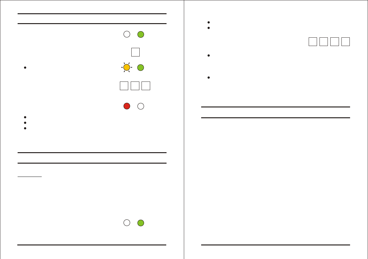
1) Enter Programming Mode
2) Press "4" to enter Menu 4
The Transmit LED will
flash orange.
3) Enter the new 3-digit code
you wish to set as
Facility Code
4) System returns to
Transmit Mode
You will hear one beep
The Program LED will turn off
The Transmit LED will turn red
Note: - Facility codes can be in the range of 000 to 255.
Warning:
You must be very careful before using this command!
Doing so will erase the entire memory which includes
all User and Special Codes, and return all codes to
their factory defaut settings.
1) Enter Programming Mode
Transmit Program
GREEN
Transmit Program
RED
???
Transmit Program
GREEN
ORANGE
Transmit Program
GREEN
4

Page 22 06/04
AYC-G64
Limited Lifetime Warranty
ROSSLARE ENTERPRISES LIMITED S (Rosslare) LIMITED
LIFETIME WARRANTY is applicable worldwide. This warranty
supersedes any other warranty. Rosslare's LIMITED LIFETIME
WARRANTY is subject to the following conditions:
WARRANTY
Warranty of Rosslare's products extends to the original purchaser of
the Rosslare product and is not transferable.
WARRANTY DURATION
Rosslare warrants this product against defects in material and/or
workmanship for the life of the product from the date of original
purchase to the original purchaser.
WARRANTY COVERAGE
Rosslare will repair or replace, at its option, any product which
under normal conditions of use and service proves to be defective
in material or workmanship. No charge will be made for labor or
parts with respect to defects covered by this warranty, provided that
the work is done by Rosslare or a Rosslare authorized service
center. This warranty does not cover expenses incurred in the
transportation, removal or reinstallation of the product, whether or
not proven defective. Replacement or repairs furnished under this
warranty are subject to the same terms and conditions of the
original warranty.
EXCLUSIONS AND LIMITATIONS
Specifically excluded from this warranty are failures caused by
abuse, neglect, misuse, improper operation, normal wear, accident,
improper maintenance or modification. This warranty does not cover
repair or replacement where normal use has exhausted the life of a
part or instrument. Service life of the product is dependent upon the
care it receives and the conditions under which it has to operate. In
no event shall Rosslare be liable for incidental or consequential
damages.
, ,
Page 23 06/04
AYC-G64
LIMITED LIFETIME WARRANTY TERMS
The terms of this warranty may not be varied by any person,
whether or not purporting to represent or act on behalf of Rosslare.
This warranty represents the full extent of Rosslare's
responsibility. Repair, replacement, or refund of the original
purchase price, of the product is the exclusive remedy. This
limited lifetime warranty is provided in lieu of all other
warranties. All other warranties expressed or implied,
including without limitation, implied warranties of
merchantability and fitness for a particular purpose, are
specifically excluded. In no event shall Rosslare be liable for
damages in excess of the purchase price of the product, or for
any other incidental, consequential or special damages,
including but not limited to loss of use, loss of time,
commercial loss, inconvenience, and loss of profits, arising
out of the installation, use, or inability to use such product, to
the fullest extent that any such loss or damage may be
disclaimed by law. This warranty shall become null and void in the
event of a violation of the provisions of this limited warranty.
Certifications:
Canada/UL 294 Listed
FCC Certification, United States
Canada Certification

AYC-G64 Page 24 06/04
Technical Support
International:
Rosslare Enterprises Ltd.
905-912 Wing Fat Industrial Bldg.,
12 Wang Tai Road, Kowloon Bay,
Hong Kong.
http://www.rosslaresecurity.com
Tel: (852) 2795 5630
Fax: (852) 2795 1508
E-mail: info@rosslare.com.hk
United States and Canada:
Rosslare NAPDC
Suite 238, 200 East Howard Street,
Des Plaines, IL 60018
USA
http://www.rosslaresecurity.com
Tel: (866) 262 8633 (Toll-Free)
Tel: (847) 827 6330 (Direct)
Fax: (847) 827 6433
E-mail: support@rosslare.net