Rosslare 30A303 Proximity and Keypad Reader User Manual AYC Q64B Instruction Manual 130305
Rosslare Enterprises Ltd Proximity and Keypad Reader AYC Q64B Instruction Manual 130305
Rosslare >
Contents
- 1. Users Manual F64
- 2. Users Manual G64
- 3. Users Manual Q64
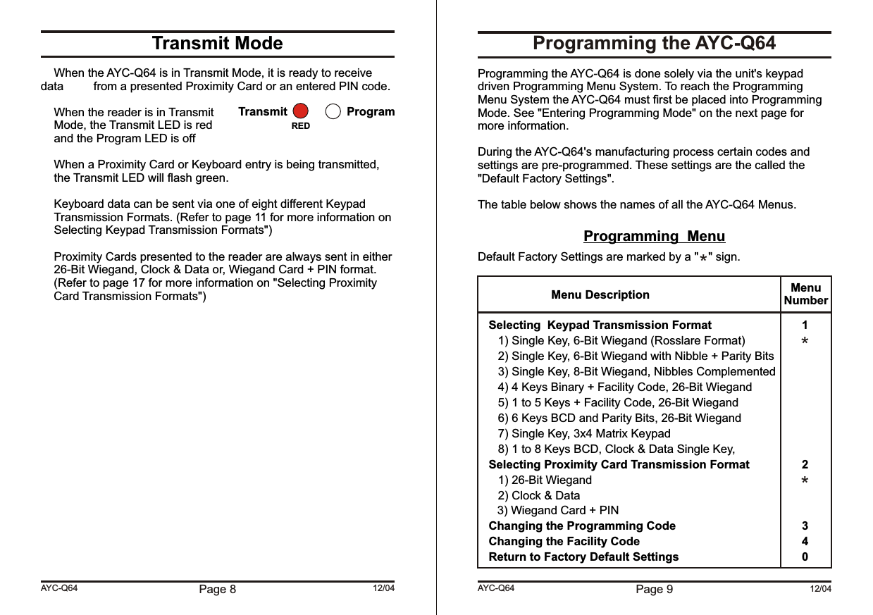
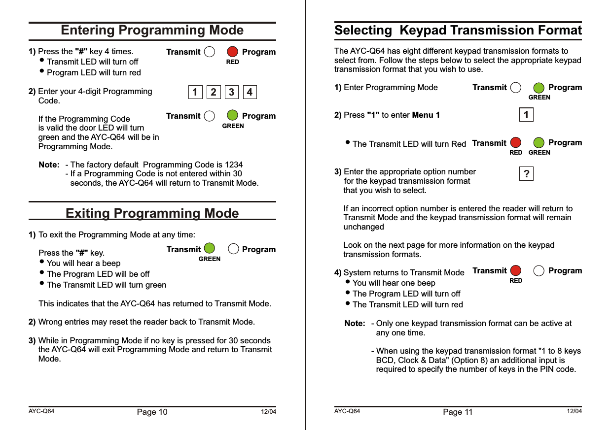
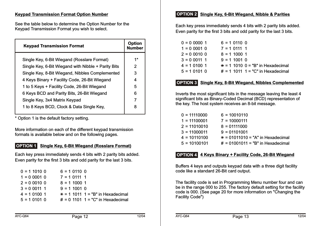
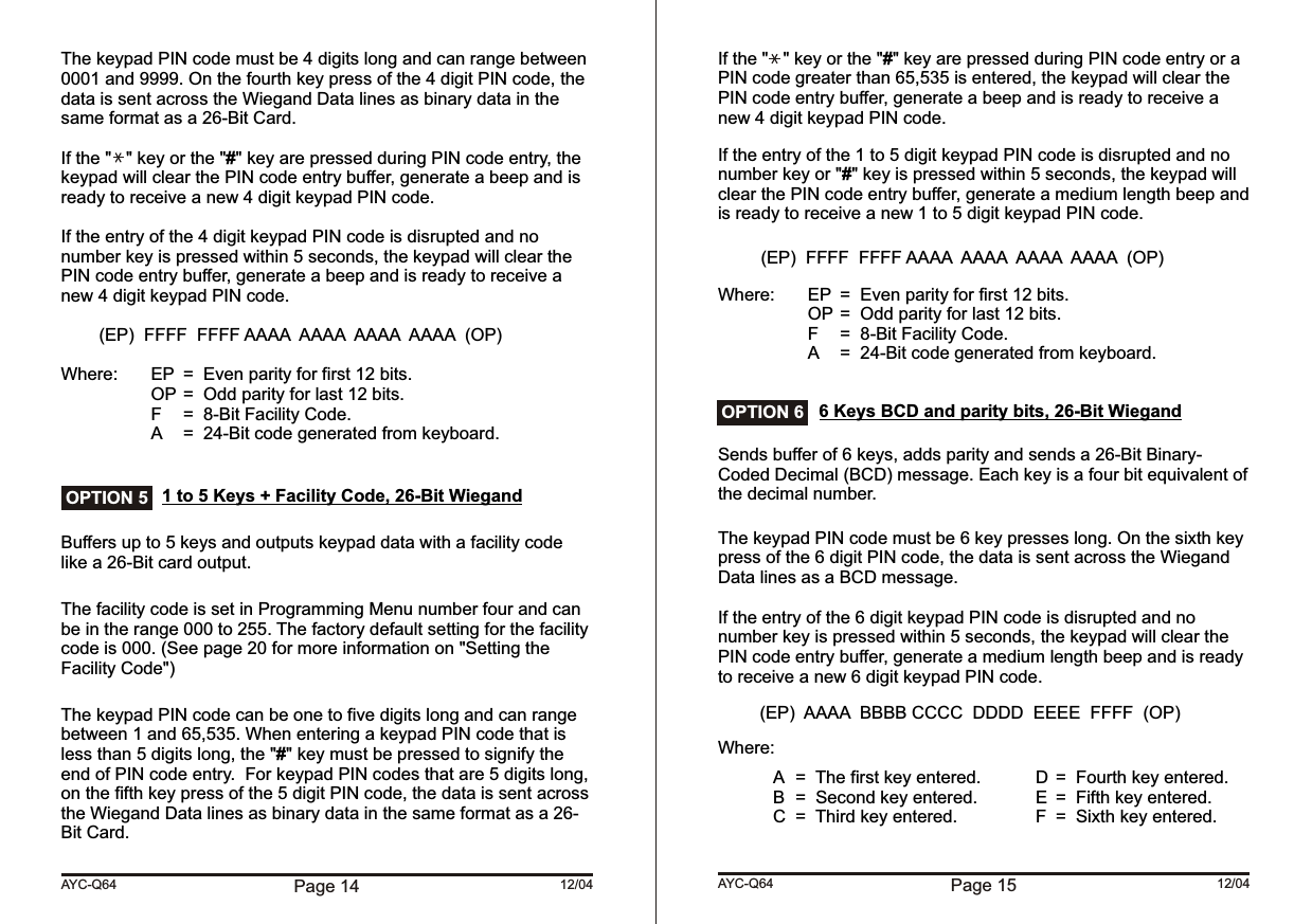
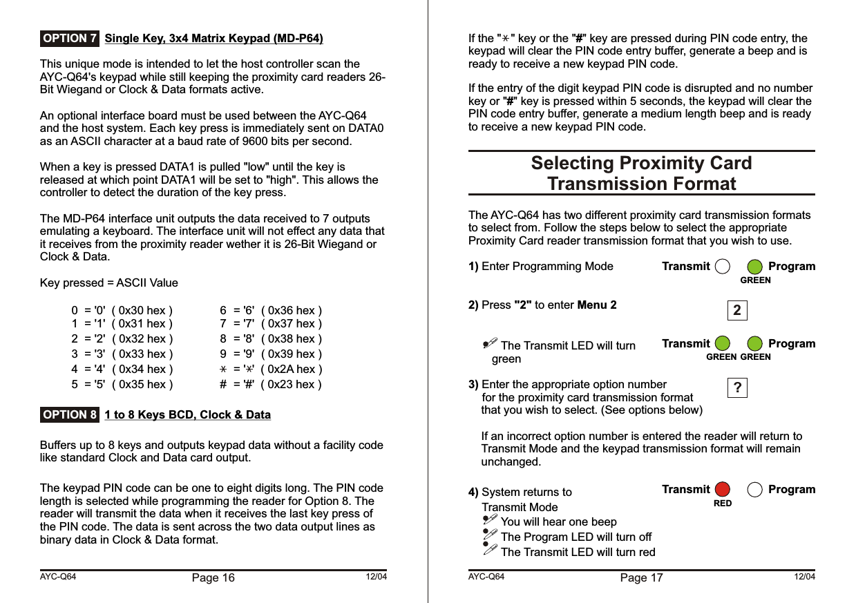
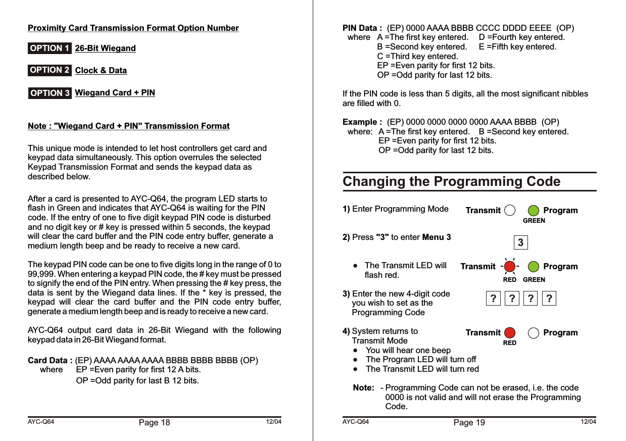
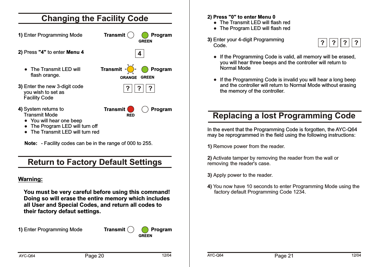
Users Manual Q64