Rosslare AY-Z12 Long Range Multi Reader AY-Z12 User Manual AY Z12 Installation Manual
Rosslare Enterprises Ltd Long Range Multi Reader AY-Z12 AY Z12 Installation Manual
Rosslare >
Users Manual
Long range Multi Reader
AY-Z12
Installation Guide
May 2009

Table of Contents
AY-Z12 Installation Manual Page ii
Table of Contents
1. Introduction......................................................................3
2. Technical Specifications ..................................................5
3. Installation........................................................................6
3.1 The Installation Kit...................................................6
3.2 Installing the AY-Z12 Long Range Reader:.............6
4. Wiring Instructions..........................................................9
5. Operation Instructions ..................................................10
Appendix A: Limited Warranty...................................11
Appendix B: Technical Support ...................................13
Introduction
1. Introduction
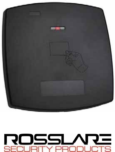
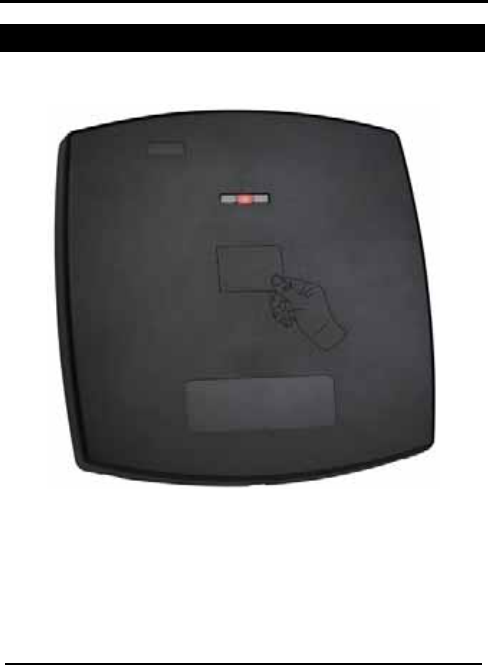
The AY-Z12 Long-range Reader is an RFID proximity card reader,
utilized with access control systems.
Figure 1 The AY-Z12 Long-Range Reader
This Manual contains the following information:
• Installation
• Wiring Instructions
• Operation Instructions
Page 3 AY-Z12 Installation Manual

Introduction
AY-Z12 Installation Manual Page 4
The AY-Z12, while easy to install and set up, must be installed
professionally.
This product has only one available channel.
Pursuant to FCC §15.21 [ 54 FR 17714 , Apr. 25, 1989, as amended
at 68 FR 68545 , Dec. 9, 2003], changes or modifications made to
equipment, which are not expressly approved by Rosslare
Enterprises, Ltd., may void the user's authority to operate the
equipment.

Technical Specifications
AY-Z12 Installation Manual
Page 5
2. Technical Specifications
Electrical Characteristics
Power Supply Type Linear type - recommended
Operating Voltage Range
10 - 16VDC
Absolute Maximum
(non-operating) 18VDC
Input Current Standby: 280mA
Read: 330mA
Tamper Output Open collector, active low, max.
sink current 30mA
Maximum Cable Distance
to Controller 500 ft (150 meters)
Card Read Distance Weigand 26 output format with a
23.6" (60 cm) maximum read
range*
Environmental Characteristics
Operating Temp. Range -22°F to 145° F (-30°C to 63°C)
Operating Humidity 0 – 95% (non-condensing)
Suitable for outdoor use (IP54)
Dimensions
Height x Width x Depth 11.81" x 11.81" x 1.0"
300mm x 300mm x 25.4 mm
Weight 2.35 Lbs. (1066g)
* Measured using Rosslare Proximity Card AT-R14 or equivalent. Range also
depends on electrical environment and proximity to metal.
Installation
3. Installation
3.1 The Installation Kit
The Installation kit comprises of the following items that are to be
used during the installation procedure:
• One Installation Template
• Four pan head screws & wall plugs
• One L shaped security screw tool
• Three Security screws
3.2 Installing the AY-Z12 Long Range Reader:
AY-Z12 Installation Manual Page 6
Installation
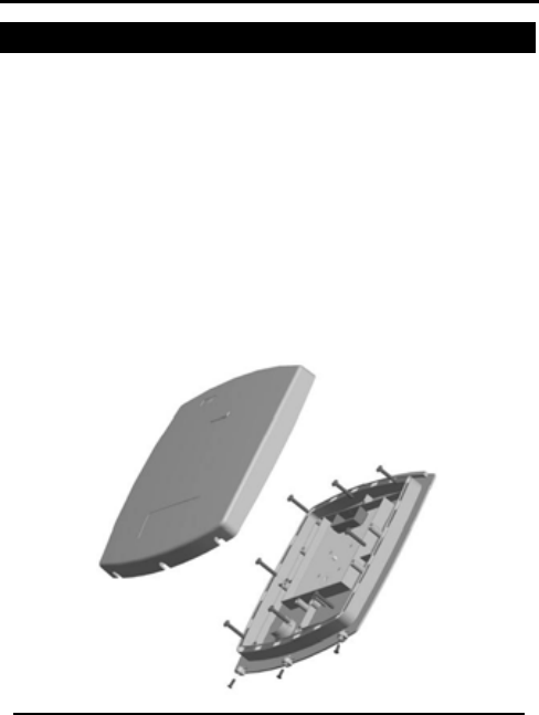
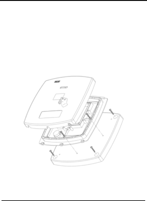
Figure 2: Removing the Top Cover
Figure 2 shows the front view of the AY-Z12 Long-Range Reader.
When installing the reader, you must remove the snap-off cover to
access the screw holes.
The Reader must be mounted with the appropriate screws (not
supplied), as described in the template provided.
Installing the unit on metal surfaces will reduce the read range
considerably, to decrease the affect of the metal surface use
Rosslare’s MP-Z02 Spacer (sold separately) as described in the
image below for a max range of 43cm (17 inch).
Figure 3: Installing the unit with the MP-Z02 spacer
Page 7 AY-Z12 Installation Manual

Installation
AY-Z12 Installation Manual Page 8
To Install the Reader:
1. Determine an approximate location for the installation of the
Reader.
2. Peel off the back of the self-adhesive installation label
template and locate it at the required location.
3. Using the template as a guide, drill the holes (the size of
which are indicated in the template) to install the Reader or
spacer onto the surface.
4. Drill a 7/16” (10mm) hole for the cable. In the event that you
are installing the reader on metal, place a grommet or
electrical tape around the edge of the hole and use the MP-
Z02 spacer.
5. Route the interface cable from the Reader to the Controller.
A linear type power supply is recommended.
Wiring Instructions
4. Wiring Instructions
The AY-Z12 Reader is supplied with an 18” pigtail, comprising a 6-
conductor cable.
To connect the Reader to the Controller:
1. Prepare the Reader cable by cutting its jacket back 1¼” and
strip the insulation from the wires, ½”.
2. Prepare the Controller cable by cutting its jacket back 1¼”
and strip the insulation from the wires, ½”.
3. Splice the Reader’s pigtail wires to the corresponding
Controller wires and cover each joint with insulating tape.
If the tamper output is being utilized, connect the purple wire
to the correct input on the Controller.
Reader Color Weigand Output
10~16 VDC Red DC+Input
Shield / Ground Black Ground
Data 1 White Data 1
Data 0 Green Data 0
LEDCTL Brown LED Control
Tamper Purple Tamper
4. Trim and cover all unused conductors.
Note:
• The individual wires from the Reader are color-coded according
the Wiegand standard.
• When using a separate power supply for the Reader, this supply
and that of the Controller, must have a common ground.
• The Reader’s cable shield wire should preferably be attached
to an earth ground, or a signal ground connection at the panel,
or power supply end of the cable. This configuration is best for
shielding the Reader cable from external interference
Page 9 AY-Z12 Installation Manual

Operation Instructions
AY-Z12 Installation Manual Page 10
5. Operation Instructions
The Reader should be tested after wiring it to a power supply and
the Controller.
To test the Reader:
1. Power up the Reader. The LED flashes green on power up (it
may flash orange), and the Beeper sounds twice, at which
point it begins an auto-calibration procedure, this can take
up to two seconds, when the calibration is complete a third
beep will sound, thus indicating that the Reader is working
properly. The LED returns to its idle state (red).
2. Present the appropriate type of proximity card to the
Reader. The LED will flash green briefly and a short beep is
emitted, thus indicating that the card was read properly.
The Reader transmits the card's data to the Controller; the
Controller checks the data, if the card transmission is valid, the
LED can change briefly to green. Refer to the Controller’s
description of LED operation for Controllers with Reader LED
control. The LED then returns to its idle state (red)
The range is measured using a Rosslare Proximity Card (P/N AT-
11/12) or equivalent. The range also depends on electrical
environment and/or proximity to metal.

Limited Warranty
AY-Z12 Installation Manual
Page 11
Appendix A: Limited Warranty
ROSSLARE ENTERPRISES LIMITED S (Rosslare) FIVE YEARS LIMITED WARRANTY
is applicable worldwide. This warranty supersedes any other warranty. Rosslare's FIVE
YEARS LIMITED WARRANTY is subject to the following conditions:
Warranty
Warranty of Rosslare's products extends to the original purchaser (Customer) of the
Rosslare product and is not transferable.
Products Covered By This Warranty and Duration
ROSSLARE ENTERPRISES LTD. AND / ORSUBSIDIARIES (ROSSLARE) warrants that
the AY-Z12 RFID long-range proximity card Reader, to be free from defects in materials
and assembly in the course of normal use and service. The warranty period commences
with the date of shipment to the original purchaser and extends for a period of 5 years (60
Months).
Warranty Remedy Coverage
In the event of a breach of warranty, ROSSLARE will credit Customer with the price of the
Product paid by Customer, provided that the warranty claim is delivered to ROSSLARE by
the Customer during the warranty period in accordance with the terms of this warranty.
Unless otherwise requested by ROSSLARE ENTERPRISES LTD. AND / OR
SUBSIDIARIES representative, return of the failed product(s) is not immediately required.
If ROSSLARE has not contacted the Customer within a sixty (60) day holding period
following the delivery of the warranty claim, Customer will not be required to return the
failed product(s). All returned Product(s), as may be requested at ROSSLARE
ENTERPRISES LTD. AND /OR SUBSIDIARY’S sole discretion, shall become the property
of ROSSLARE ENTERPRISES LTD. AND /OR SUBSIDIARIES.
To exercise the warranty, the user must contact Rosslare Enterprises Ltd. to obtain an
RMA number after which, the product must be returned to the Manufacturer freight prepaid
and insured
In the event ROSSLARE chooses to perform a product evaluation within the sixty (60) day
holding period and no defect is found, a minimum US$ 50.00 or equivalent charge will be
applied to each Product for labor required in the evaluation.
Rosslare will repair or replace, at its discretion, any product that under normal conditions
of use and service proves to be defective in material or workmanship. No charge will be
applied for labor or parts with respect to defects covered by this warranty, provided that
the work is done by Rosslare or a Rosslare authorized service center.

Limited Warranty
AY-Z12 Installation Manual Page 12
Exclusions and Limitations
ROSSLARE shall not be responsible or liable for any damage or loss resulting from the
operation or performance of any Product or any systems in which a Product is
incorporated. This warranty shall not extend to any ancillary equipment not furnished by
ROSSLARE, which is attached to or used in conjunction with a Product, nor to any Product
that is used with any ancillary equipment, which is not furnished by ROSSLARE.
This warranty does not cover expenses incurred in the transportation, freight cost to the
repair center, removal or reinstallation of the product, whether or not proven defective.
Specifically excluded from this warranty are any failures resulting from Customer's
improper testing, operation, installation, or damage resulting from use of the Product in
other than its normal and customary manner, or any maintenance, modification, alteration,
or adjustment or any type of abuse, neglect, accident, misuse, improper operation, normal
wear, defects or damage due to lightning or other electrical discharge. This warranty does
not cover repair or replacement where normal use has exhausted the life of a part or
instrument, or any modification or abuse of, or tampering with, the Product if Product
disassembled or repaired in such a manner as to adversely affect performance or prevent
adequate inspection and testing to verify any warranty claim.
ROSSLARE does not warrant the installation, maintenance, or service of the Product.
Service life of the product is dependent upon the care it receives and the conditions under
which it has to operate.
In no event shall Rosslare be liable for incidental or consequential damages.
Limited Warranty Terms
THIS WARRANTY SETS FORTH THE FULL EXTENT OF ROSSLARE ENTERPRISES LTD. AND
IT’S SUBSIDIARY'S WARRANTY
THE TERMS OF THIS WARRANTY MAY NOT BE VARIED BY ANY PERSON, WHETHER OR
NOT PURPORTING TO REPRESENT OR ACT ON BEHALF OF ROSSLARE.
THIS LIMITED WARRANTY IS PROVIDED IN LIEU OF ALL OTHER WARRANTIES. ALL OTHER
WARRANTIES EXPRESSED OR IMPLIED, INCLUDING WITHOUT LIMITATION, IMPLIED
WARRANTIES OF MERCHANTABILITY AND FITNESS FOR A PARTICULAR PURPOSE, ARE
SPECIFICALLY EXCLUDED.
IN NO EVENT SHALL ROSSLARE BE LIABLE FOR DAMAGES IN EXCESS OF THE
PURCHASE PRICE OF THE PRODUCT, OR FOR ANY OTHER INCIDENTAL,
CONSEQUENTIAL OR SPECIAL DAMAGES, INCLUDING BUT NOT LIMITED TO LOSS OF
USE, LOSS OF TIME, COMMERCIAL LOSS, INCONVENIENCE, AND LOSS OF PROFITS,
ARISING OUT OF THE INSTALLATION, USE, OR INABILITY TO USE SUCH PRODUCT, TO
THE FULLEST EXTENT THAT ANY SUCH LOSS OR DAMAGE MAY BE DISCLAIMED BY LAW.
THIS WARRANTY SHALL BECOME NULL AND VOID IN THE EVENT OF A VIOLATION OF THE
PROVISIONS OF THIS LIMITED WARRANTY.

Technical Support
AY-Z12 Installation Manual
Page 13
Appendix B: Technical Support
Asia Pacific, Middle East, Africa
Rosslare Security Products Headquarters
905-912 Wing Fat Industrial Bldg,
12 Wang Tai Road,
Kowloon Bay Hong Kong
Tel: +852 2795-5630
Fax: +852 2795-1508
E-mail: support.apac@rosslaresecurity.com
United States and Canada
1600 Hart Court, Suite 103
Southlake, TX, USA 76092
Toll Free:+1-866-632-1101
Local:+1-817-305-0006
Fax: +1-817-305-0069
E-mail: support.na@rosslaresecurity.com
Europe
Global Technical Support & Training Center
HaMelecha 22
Rosh HaAyin, Israel 48091
Tel: +972 3 938-6838
Fax: +972 3 938-6830
E-mail: support.eu@rosslaresecurity.com
South America
Pringles 868, 1640 Martinez
Buenos Aires
Argentina
Tel: +54 11 4798-0095
Fax: +54 11 4798-2228
E-mail: support.la@rosslaresecurity.com
Web Site: www.rosslaresecurity.com

0706-0960127+02
www.rosslaresecurity.com