Rosslare AYCG6X Convertible Reader with Genuine HID Technology User Manual

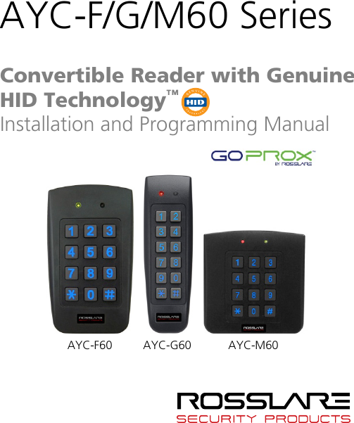
Rosslare Enterprises Ltd Convertible Reader with Genuine HID Technology

User Manual

AYC-F/G/M60 Series    Convertible Reader with Genuine HID Technology™ Installation and Programming Manual AYC-F60 AYC-G60 AYC-M60
             Copyright © 2017 by Rosslare. All rights reserved.  This manual and the information contained herein are proprietary to ROSSLARE ENTERPRISES LIMITED and/or its related companies and/or subsidiaries’ (hereafter: "ROSSLARE"). Only ROSSLARE and its customers have the right to use the information. No part of this manual may be re-produced or transmitted in any form or by any means, electronic or mechanical, for any purpose, without the express written permission of ROSSLARE. ROSSLARE owns patents and patent applications, trademarks, copyrights, or other intellectual property rights covering the subject matter in this manual.  TEXTS, IMAGES, AND ILLUSTRATIONS INCLUDING THEIR ARRANGEMENT IN THIS DOCUMENT ARE SUBJECT TO THE PROTECTION OF COPYRIGHT LAWS AND OTHER LEGAL RIGHTS WORLDWIDE. THEIR USE, REPRODUCTION, AND TRANSMITTAL TO THIRD PARTIES WITHOUT EXPRESS WRITTEN PERMISSION MAY RESULT IN LEGAL PROCEEDINGS. The furnishing of this manual to any party does not give that party or any third party any license to these patents, trademarks, copyrights or other intellectual property rights, except as expressly provided in any written agreement of ROSSLARE.  ROSSLARE reserves the right to revise and change this document at any time, without being obliged to announce such revisions or changes beforehand or after the fact.
Table of Contents AYC-F/G/M60 Series Installation and Programming Manual iii Table of Contents 1. Introduction ................................................................ 9 1.1 Box Content ........................................................................... 9 1.2 Ancillary Equipment .............................................................. 10 2. Technical Specifications ............................................ 11 3. Installation ................................................................ 13 3.1 Mounting ............................................................................. 13 3.2 Wiring .................................................................................. 14 3.2.1 Wiring the Unit as a Reader .......................................................... 14 3.2.2 Wiring the Unit as a Controller ..................................................... 15 4. Reader Operation ...................................................... 18 4.1 Standby Mode ...................................................................... 18 4.2 Programming as a Reader ...................................................... 18 4.2.1 Entering Programming Mode ........................................................ 20 4.2.2 Exiting Programming Mode .......................................................... 20 4.2.3 Selecting Keypad Transmission Format ......................................... 21 4.2.4 Selecting HID Prox Card Transmission Format ............................... 26 4.2.5 Selecting Rosslare Proximity Card Transmission Format ................. 26 4.2.6 Changing the Programming Code ................................................ 28 4.2.7 Changing the Facility Code ........................................................... 29 4.2.8 Setting the Backlight Behavior ...................................................... 29 4.2.9 Setting the Credential Format ....................................................... 30 4.2.10 Return to Factory Default Settings ................................................ 30 4.2.11 Replacing a Lost Programming Code ............................................ 31 5. Controller Operation ................................................. 32
Table of Contents iv AYC-F/G/M60 Series Installation and Programming Manual 5.1 Normal, Secure, and Master Users .......................................... 32 5.2 Modes of Operation .............................................................. 33 5.2.1 Normal Mode ............................................................................... 33 5.2.2 Bypass Mode ................................................................................ 33 5.2.3 Secure Mode ................................................................................ 34 5.2.4 Changing the Modes of Operation ............................................... 34 5.3 Auxiliary Input and Output..................................................... 36 5.4 Door Alarms ......................................................................... 36 5.5 Internal Case and Back Tamper .............................................. 36 5.6 Lockout Feature (Keypad/Card Tamper) .................................. 36 5.7 REX Function ........................................................................ 37 5.8 Secured Intelligent Power Supply ........................................... 37 5.9 Programming as a Controller ................................................. 38 5.9.1 Entering Programming Mode ........................................................ 39 5.9.2 Exiting Programming Mode .......................................................... 39 5.9.3 Changing Lock Strike Code .......................................................... 40 5.9.4 Changing Auxiliary Code .............................................................. 40 5.9.5 Changing the Programming Code ................................................ 41 5.9.6 Changing the Normal/Secure Code .............................................. 42 5.9.7 Changing the Normal/Bypass Code and Door Chime Settings ...... 42 5.9.8 Setting Fail Safe/Secure Operation, Tamper Siren and Lock Strike Release Time ................................................................................. 43 5.9.9 Defining the Auxiliary Input and Output ....................................... 44 5.9.10 Setting the Lockout Feature .......................................................... 51 5.9.11 Setting the Backlight Behavior ...................................................... 52 5.9.12 Selecting the Credential Format .................................................... 52 5.9.13 Enrolling Primary and Secondary Codes ........................................ 53 5.9.14 Deleting Primary and Secondary Codes ......................................... 56
Table of Contents AYC-F/G/M60 Series Installation and Programming Manual  v 5.9.15 Relay Codes Assignment ............................................................... 59 5.9.16 PIN Code Length/Factory Default Settings ..................................... 61 5.9.17 Replacing a Lost Programming Code ............................................ 62 5.9.18 Replacing a Lost Normal/Secure Code ........................................... 62 A. Declaration of Conformity........................................ 63 B. Limited Warranty ...................................................... 64
List of Figures vi AYC-F/G/M60 Series Installation and Programming Manual List of Figures Figure 1: Drilling and Mounting Holes ............................................................. 13 Figure 2: Controller Application Wiring Diagram ............................................. 16 Figure 3: Controller Wiring – Using the Internal Power .................................... 17 Figure 4: Controller Wiring – Using the External Power ................................... 17
List of Tables AYC-F/G/M60 Series Installation and Programming Manual vii List of Tables Table 1: Wiring the Reader to the Controller ................................................... 14 Table 2: Wiring the Unit as a Controller........................................................... 15 Table 3: Reader Programming Menu ............................................................... 19 Table 4: Controller Programming Menu .......................................................... 38 Table 5: Quick Reference Guide for Auxiliary Mode Setting ............................. 46
Notice and Disclaimer viii AYC-F/G/M60 Series Installation and Programming Manual Notice and Disclaimer This manual’s sole purpose is to assist installers and/or users in the safe and efficient installation and usage of the system and/or product, and/or software described herein. BEFORE ATTEMPTING TO INSTALL AND/OR USE THE SYSTEM, THE INSTALLER AND THE USER MUST READ THIS MANUAL AND BECOME FAMILIAR WITH ALL SAFETY REQUIREMENTS AND OPERATING PROCEDURES.  The system must not be used for purposes other than those for which it was designed.  The use of the software associated with the system and/or product, if applicable, is subject to the terms of the license provided as part of the purchase documents.  ROSSLARE exclusive warranty and liability is limited to the warranty and liability statement provided in an appendix at the end of this document.  This manual describes the maximum configuration of the system with the maximum number of functions, including future options. Therefore, not all functions described in this manual may be available in the specific system and/or product configuration you purchased.  Incorrect operation or installation, or failure of the user to effectively maintain the system, relieves the manufacturer (and seller) from all or any responsibility for consequent noncompliance, damage, or injury.  The text, images and graphics contained in the manual are for the purpose of illustration and reference only.  All data contained herein subject to change without prior notice.  In no event shall manufacturer be liable for any special, direct, indirect, incidental, consequential, exemplary or punitive damages (including, without limitation, any and all damages from business interruption, loss of profits or revenue, cost of capital or loss of use of any property or capital or injury).  All graphics in this manual are for reference only, some deviation between the image(s) and the actual product may occur.  All wiring diagrams are intended for reference only, the photograph or graphic of the PCB(s) are intended for clearer illustration and understanding of the product and may differ from the actual PCB(s).
Introduction AYC-F/G/M60 Series Installation and Programming Manual  9 1. Introduction The AYC-F/G/M60 is a series of Rosslare goPROX & PIN readers with Genuine HID Technology™, as well as Rosslare's Convertible technology. These units automatically determine whether to function as a reader or as a secured standalone controller. If the unit is connected to a standard access control unit, then it functions as a reader. If the unit is connected to a Rosslare secured intelligent power supply such as the PS-A25T, PS-C25T, or PS-C25TU, it functions as a secured standalone controller. As a reader, the units can read all HID Prox cards/tags (125 kHz FSK) using Genuine HID Technology and outputs HID Prox card data in Wiegand according to the number of bits of data stored on the card. The units also read Rosslare proximity cards (125 kHz) and can output Rosslare proximity card data as Wiegand 26-Bit, Clock & Data, and Wiegand + PIN. As a controller, the units accept up to 500 users, and allow entry via a personal identification number (PIN) and/or by presenting a proximity card. The PIN code length for the controller has several options. The PIN code length can be a set number of 4, 5, or 6 digits or it can be flexible from 4 to 8 digits. 1.1 Box Content Before beginning, verify that all of the following is in the box. If anything is missing, please report the discrepancy to your nearest Rosslare office.  One AYC-F/G/M60 unit  Installation kit  Installation and operating instructions
Introduction 10 AYC-F/G/M60 Series Installation and Programming Manual 1.2 Ancillary Equipment The following equipment is required to complete your installation:  When functioning as a reader: Compatible Host Controller (not supplied) – Any host controller that accepts either Wiegand or Clock & Data communication protocols. Multiple keypad formats are supported. For a complete list, see Section  4.2.3. UL installations require a UL listed access control units such as Rosslare's AC-215U and AC-225U.  When functioning as a controller: Secured intelligent power supply – such as the PC-25T, PS-A25T, PS-C25T, or PS-C25TU secure controllers.  Only PS-C25TU can be used for UL-294 compliant installations. This unit connects to the following:  Electric lock strike mechanism or a magnetic lock device, which implements fail safe (power to lock) or fail secure (power to open) functions  Request to Exit (REX) button – normally open type. Switch is closed when pressed.  Door monitor switch Rosslare accessories can be found on www.rosslaresecurity.com.
Technical Specifications AYC-F/G/M60 Series Installation and Programming Manual 11 2. Technical Specifications Electrical Characteristics Power Supply Type Linear (recommended) Operating Voltage Range 5–16 VDC (when used as a controller, provided by the secured intelligent power supply) Input current standby (12 VDC) 100 mA Input Current Max (16 VDC) 140 mA LED Control Input Dry contact N.O. Tamper Output Open collector, active low, 32 mA max sink current  Cable Distance to Host Controller Up to 150 m (500 ft) using an 18 AWG cable Max. Proximity Card Read Range* 60 mm (2.4 in.) Proximity Card Modulation Rosslare proximity/HID Prox at 125 kHz Proximity Card Compatibility Rosslare proximity/HID Prox cards Card Transmit Format (Reader) Rosslare proximity cards: Wiegand 26-Bit, or Clock & Data HID Prox cards: According to card type Keypad Transmit Format (Reader) Programmable PIN code formats (see Section  4.2.3) LED Indicators Two tri-colored LEDs Communication Data1/C1, Data0/C2–open collector, 5 V termination *  Measured using a Rosslare proximity card or equivalent. Range also depends on electrical environment and proximity to metal.
Technical Specifications 12 AYC-F/G/M60 Series Installation and Programming Manual Environmental Characteristics Operating Temp. Range -30°C to 65°C (-22°F to 150°F) Operating Humidity Range 0 to 95% (non-condensing) Outdoor Usage Weather-resistant, meets IP65, epoxy-potted, suitable for indoor and outdoor use Physical Characteristics Size (Height x Width x Depth) F: 120 x 76 x 21 mm (4.7 x 3.0 x 0.8 in.) G: 137 x 44 x 21 mm (5.4 x 1.7 x 0.8 in.) M: 93 x 93 x 18 mm (3.6 x 3.6 x 0.7 in.) Weight F: 230 g (8.1 oz) G: 175 g (6.2 oz) M: 185 g (6.5 oz)
Installation AYC-F/G/M60 Series Installation and Programming Manual 13 3. Installation  Installation of an RFID reader adjacent to metallic surfaces might alter the reader’s specifications. To diminish this interference, use a plastic spacer when mounting the reader. Before starting, select the location to mount the unit. This location should be at shoulder height. 3.1 Mounting Before starting, select the location to mount the unit. This location should be at shoulder height. To mount the unit: 1. Peel off the back of the self-adhesive installation template and attach the template to the required location. 2. Using the template as a guide, drill holes according to how you want to mount the unit (Figure 1). Figure 1: Drilling and Mounting Holes    AYC-F60 AYC-G60 AYC-M60 3. Drill a 10-mm (7/16”) hole for the cable. If the surface is metal, place a grommet or electrical tape around the edge of the hole. 4. At the bottom of the unit’s case, remove the screw. 5. Carefully remove the snap-off front cover of the unit to reveal the screw holes.
Installation 14 AYC-F/G/M60 Series Installation and Programming Manual 6. Insert the unit’s cable wire into the cable hole and wire the unit as described in Section  3.2. 7. Screw the back cover to its mounting location. 8. Carefully re-attach the front cover of the unit. 9. Secure the front cover by using the supplied security Torx screw. A Torx security screw tool is provided to tighten the security Torx screw. 3.2 Wiring The unit is supplied with a 6-conductor 56-cm (22-in.) pigtail with exposed wires coated with solder. 3.2.1 Wiring the Unit as a Reader If you connect the unit to a standard access control unit, it automatically functions as a reader. To connect the unit as a reader (to a controller): 1. Select the appropriate connections according to Table 1. Table 1: Wiring the Reader to the Controller Wire Color Function Black/Shield  Ground (+) Red Vin (-) Green  Data 0/Data (D0) White Data 1/Clock (D1) Brown  LED control Purple  Tamper 2. Prepare the controller cable by cutting the cable jacket back 3.2 cm (1¼”) and strip the wire 1.3 cm (½”). 3. Splice the reader’s pigtail wires to the corresponding controller wires and cover each joint with insulating tape. 4. If the tamper output is being utilized, connect the purple wire to the correct input on the controller.
Installation AYC-F/G/M60 Series Installation and Programming Manual 15 5. Trim and cover all conductors that are not used.  • The individual wires extending from the reader are color-coded according to the required Wiegand standard. • When using a separate power supply for the reader, this supply and the controller’s power supply must have a common ground. A linear power supply is recommended. • Attach the cable shield wire on the reader to an earth ground (best), or to a signal ground connection at the panel or power supply end of the cable. This configuration is best for shielding the reader cable from external interference. 3.2.2 Wiring the Unit as a Controller If you connect the unit to a Rosslare PS-x25x secured power supply, it automatically functions as a controller. To connect the unit as a controller: 1. Select the appropriate connections according to Table 2. Table 2: Wiring the Unit as a Controller Controller  Wire Color  Function  Note -  Red  +DC Input  Wired to the PS-x25x +  Black  Ground  Wired to the PS-x25x C 1  White  Communication  Wired to the PS-x25x C 2  Green  Communication  Wired to the PS-x25x AUX. IN  Brown  Auxiliary Input  Wired to input N/A Purple Not in use N/A   Attach the cable shield wire on the unit to an earth ground (best). You can also attach it to a signal ground connection at the panel or power supply end of the cable. This configuration is best for shielding the controller cable from external interference. 2. Prepare the PS-x25x secured power supply’s cable by cutting the cable jacket back 3.2 cm (1¼”) and strip the wire 1.3 cm (½”). 3. Splice the controller pigtail wires to the corresponding PS-x25x secured power supply’s wires and cover each joint with insulating tape.
Installation 16 AYC-F/G/M60 Series Installation and Programming Manual 4. Trim and cover all conductors not used. 5. To connect the unit to the desired power supply option, refer to the relevant wiring diagrams that follow. Figure 2 shows the wiring for the controller application using a dual relay secured intelligent power supply. Figure 2: Controller Application Wiring Diagram
Installation AYC-F/G/M60 Series Installation and Programming Manual 17 Figure 3 shows the auxiliary output connection using the internal power. Figure 3: Controller Wiring – Using the Internal Power  Figure 4 shows the auxiliary output connection using the external power. Figure 4: Controller Wiring – Using the External Power   Transorb:1.5KE77c-Connect to load terminals(optional transorb for inductive loads,not supplied)(optional transorb for inductive loads,not supplied)
Reader Operation 18 AYC-F/G/M60 Series Installation and Programming Manual 4. Reader Operation The AYC-F/G/M60 series can function both as a reader and as a controller. If the unit is connected to standard access controller, it functions as a reader, indicated by one beep immediately after power-on reset. 4.1 Standby Mode The default mode of the reader is Standby mode. In Standby mode, the unit is ready to receive data from a presented proximity card or an entered PIN code. When the reader is in Standby mode, the left LED is red and the right LED is off.  When a proximity card is presented or a keypad entry is being transmitted, the left LED flashes green.  Keypad data can be sent via one of eight keypad transmission formats. For more information, see Section  4.2.3. Rosslare proximity cards presented to the reader can output card data as Wiegand 26-Bit, Clock & Data, and Wiegand + PIN. See Section  4.2.5 for more information. HID Prox card data is output in Wiegand according to the number of bits of data stored on the card. See Section  4.2.4 for more information. 4.2 Programming as a Reader Programming is done solely via the unit's keypad driven Programming Menu System. During the unit’s manufacturing process, certain codes and settings are pre-programmed. These settings are called the default factory settings. Green Red
Reader Operation AYC-F/G/M60 Series Installation and Programming Manual 19 Table 3 shows the names of all the reader programming menus. Default factory settings are marked by *. Table 3: Reader Programming Menu Menu Description Default 1  Selecting Keypad Transmission Format Single Key, Wiegand 6-Bit (Rosslare Format) Single Key, Wiegand 6-Bit with Nibble + Parity Bits Single Key, Wiegand 8-Bit, Nibbles Complemented 4 Keys Binary + Facility code, Wiegand 26-Bit 1 to 5 Keys + Facility code, Wiegand 26-Bit 6 Keys Binary-Coded Decimal (BCD) and Parity Bits, Wiegand 26-Bit Single Key, 3x4 Matrix Keypad 1 to 8 Keys BCD, Clock & Data Single key, Wiegand 4-Bit  * 2  Selecting Rosslare Proximity Card Transmission Format Wiegand 26-Bit Clock & Data Wiegand Card + PIN  * 3  Changing the Programming code 1234 4  Changing the Facility code 0 6  Setting the Backlight Always off Always on 10 sec. backlight after key press otherwise off 10 sec. backlight after key press otherwise dimmed   * 6  Setting Credential Format Rosslare Proximity HID Prox Rosslare Proximity + HID Prox    * 0  Return to Factory Default Settings
Reader Operation 20 AYC-F/G/M60 Series Installation and Programming Manual 4.2.1 Entering Programming Mode To reach the Programming Menu System, the unit must first be placed into Programming mode.  • The factory 4-digit Programming code is 1234. • If a Programming code is not entered within 30 seconds, the unit returns to Standby mode. To enter Programming mode: 1. Press # four times.   The left LED turns off and the right LED turns red.  2. Enter your 4-digit Programming code.   If the Programming code is valid, the right LED turns green.   If the Programming code is invalid, you hear a long beep and the reader returns to Standby mode. 4.2.2 Exiting Programming Mode To exit Programming mode: 1. Press # to exit Programming mode at any time.   You hear a beep.  The left LED turns red and the right LED turns off.  This indicates that the unit has returned to Standby mode. Wrong entries may reset the reader back to Standby mode. If no key is pressed for 30 seconds while in Programming mode, the unit exits Programming mode and returns to Standby mode. Red Green
Reader Operation AYC-F/G/M60 Series Installation and Programming Manual 21 4.2.3 Selecting Keypad Transmission Format There are nine keypad transmission formats.  • Only one keypad transmission format can be active at any one time. • When using the keypad transmission format "1 to 8 keys BCD, Clock & Data" (Option 8) an additional input is required to specify the number of keys in the PIN code. To select the keypad transmission format: 1. Enter Programming mode.  2. Press 1 to enter Menu 1.  The left LED turns red.  3. Enter one of the following codes:  1 – Single Key, Wiegand 6-Bit (Rosslare Format) (default)  2 – Single Key, Wiegand 6-Bit with Nibble + Parity Bits  3 – Single Key, Wiegand 8-Bit, Nibbles Complemented  4 – 4 Keys Binary + Facility Code, Wiegand 26-Bit  5 – 1 to 5 Keys + Facility Code, Wiegand 26-Bit  6 – 6 Keys BCD and Parity Bits, Wiegand 26-Bit  7 – Single Key, 3x4 Matrix Keypad  8 – 1 to 8 Keys BCD, Clock & Data Single Key  9 – Single Key, Wiegand 4-Bit  When selecting Option 8, the Program LED turns orange, awaiting an additional key input to select the number of keys.  You hear three beeps. The system returns to Standby mode.   Red Red Green Green
Reader Operation 22 AYC-F/G/M60 Series Installation and Programming Manual If an incorrect option number is entered, the reader returns to Standby mode and the keypad transmission format remains unchanged. 4.2.3.1 Single Key, Wiegand 6-Bit (Rosslare Format) Each key press immediately sends 4 bits with 2 parity bits added – even parity for the first 3 bits and odd parity for the last 3 bits. 0 = 1 1010 0 ="A" in Hexadecimal  6 = 1 0110 0 1 = 0 0001 0  7 = 1 0111 1 2 = 0 0010 0  8 = 1 1000 1 3 = 0 0011 1  9 = 1 1001 0 4 = 1 0100 1 * = 1 1011 1 ="B" in Hexadecimal 5 = 1 0101 0  # = 0 1100 1 ="C" in Hexadecimal 4.2.3.2 Single Key, Wiegand 6-Bit Nibble and Parities Each key press immediately sends 4 bits with 2 parity bits added – even parity for the first 3 bits and odd parity for the last 3 bits. 0 = 0 0000 1  6 = 1 0110 0 1 = 0 0001 0 7 = 1 0111 1 2 = 0 0010 0 8 = 1 1000 1 3 = 0 0011 1 9 = 1 1001 0 4 = 1 0100 1 * = 1 1010 0 = "A" in Hexadecimal 5 = 1 0101 0 # = 1 1011 1 = "B" in Hexadecimal 4.2.3.3 Single Key, Wiegand 8-Bit Nibbles Complemented This options inverts the most significant bits in the message leaving the least 4 significant bits as BCD representation of the key. The host system receives an 8-bit message. 0 = 11110000 6 = 10010110 1 = 11100001 7 = 10000111 2 = 11010010 8 = 01111000 3 = 11000011 9 = 01101001 4 = 10110100 * = 01011010 = "A" in Hexadecimal 5 = 10100101 # = 01001011 = "B" in Hexadecimal
Reader Operation AYC-F/G/M60 Series Installation and Programming Manual 23 4.2.3.4 4 Keys Binary + Facility Code, Wiegand 26-Bit This option buffers 4 keys and outputs keypad data with a 3-digit facility code like a standard 26-bit card output. The facility code is set in Programming Menu 4 and can be in the range 000 to 255. The factory default setting for the facility code is 000 (see Section  4.2.7 for more information). The keypad PIN code is 4 digits in length and can range between 0000 and 9999. On the fourth key press of the 4-digit PIN code, the data is sent across the Wiegand Data lines as binary data in the same format as a 26-bit card. If * or # is pressed during PIN code entry, the keypad clears the PIN code entry buffer, generates a beep, and is ready to receive a new 4-digit keypad PIN code. If the entry of the 4-digit keypad PIN code is disrupted and no number key is pressed within 5 seconds, the keypad clears the PIN code entry buffer, generates a beep, and is ready to receive a new 4-digit keypad PIN code: (EP) FFFF FFFF AAAA AAAA AAAA AAAA (OP) Where: EP = Even parity for first 12 bits OP = Odd parity for last 12 bits F = 8-Bit Facility code A = 16-Bit code generated from keypad 4.2.3.5 1 to 5 Keys + Facility Code, Wiegand 26-Bit Option 5 buffers up to 5 keys and outputs keypad data with a facility code like a 26-bit card output. The facility code is set in Programming Menu 4 and can be in the range 000 to 255. The factory default setting for the facility code is 000 (see Section  4.2.7 for more information). The keypad PIN code can be one to five digits in length and can range between 1 and 65,535. When entering a keypad PIN code that is less than 5 digits in length, # must be pressed to signify the end of PIN code entry. For
Reader Operation 24 AYC-F/G/M60 Series Installation and Programming Manual keypad PIN codes that are 5 digits in length, on the fifth key press of the 5-digit PIN code, the data is sent across the Wiegand Data lines as binary data in the same format as a 26-bit card. If * is pressed during PIN code entry or a PIN code greater than 65,535 is entered, the keypad clears the PIN code entry buffer, generates a beep and is ready to receive a new 5-digit keypad PIN code. If the entry of the 1- to 5-digit keypad PIN code is disrupted and a number key or # is not pressed within 5 seconds, the keypad clears the PIN code entry buffer, generates a medium length beep, and is ready to receive a new 1- to 5-digit keypad PIN code: (EP) FFFF FFFF AAAA AAAA AAAA AAAA (OP) Where: EP = Even parity for first 12 bits OP = Odd parity for last 12 bits F = 8-Bit Facility code A = 16-Bit code generated from keypad 4.2.3.6 6 Keys BCD and Parity Bits, Wiegand 26-Bit This option sends buffer of 6 keys, adds parity, and sends a 26-bit BCD message. Each key is a four bit equivalent of the decimal number. The keypad PIN code must be 6 key presses in length. On the sixth key press of the 6-digit PIN code, the data is sent across the Wiegand Data lines as a BCD message. If the entry of the 6-digit keypad PIN code is disrupted and a number key or # is not pressed within 5 seconds, the keypad clears the PIN code entry buffer, generates a medium length beep, and is ready to receive a new 6-digit keypad PIN code: (EP) AAAA BBBB CCCC DDDD EEEE FFFF (OP) Where: EP = Even parity for first 12 bits OP = Odd parity for last 12 bits
Reader Operation AYC-F/G/M60 Series Installation and Programming Manual 25 A = The first key entered D = Fourth key entered B = Second key entered E = Fifth key entered C = Third key entered F = Sixth key entered 4.2.3.7 Single Key, 3x4 Matrix Keypad This unique mode is intended to let the host controller scan the keypad while still keeping the proximity card readers Wiegand 26-Bit or Clock & Data formats active. An optional interface board must be used between the AYC-F/G/M60 and the host system. Each key press is immediately sent on DATA0 as an ASCII character at a baud rate of 9600 bits per second. When a key is pressed, DATA1 is pulled "low" until the key is released at which point DATA1 is set to "high". This allows the controller to detect the duration of the key press. The MD-P64 interface unit outputs the data received to 7 outputs emulating a keypad. The interface unit does not affect any data that it receives from the proximity reader whether it is Wiegand 26-Bit or Clock & Data. Key pressed = ASCII Value 0 = '0' ( 0x30 hex ) 6 = '6' ( 0x36 hex ) 1 = '1' ( 0x31 hex ) 7 = '7' ( 0x37 hex ) 2 = '2' ( 0x32 hex ) 8 = '8' ( 0x38 hex ) 3 = '3' ( 0x33 hex ) 9 = '9' ( 0x39 hex ) 4 = '4' ( 0x34 hex ) *= '* ' ( 0x2A hex ) 5 = '5' ( 0x35 hex ) # = '#' ( 0x23 hex ) 4.2.3.8 1 to 8 Keys BCD, Clock & Data Option 8 buffers up to 8 keys and outputs keypad data without a facility code like standard Clock and Data card output. The keypad PIN code can be one to eight digits in length. The PIN code length is selected while programming the reader for Option 8. The reader transmits the data when it receives the last key press of the PIN code. The data is sent across the two data output lines as binary data in Clock & Data format.
Reader Operation 26 AYC-F/G/M60 Series Installation and Programming Manual If * or # is pressed during PIN code entry, the keypad clears the PIN code entry buffer, generates a beep, and is ready to receive a new keypad PIN code. If the entry of the keypad PIN code is disrupted and a number key or # is not pressed within 5 seconds, the keypad clears the PIN code entry buffer, generates a medium length beep, and is ready to receive a new keypad PIN code. 4.2.3.9 Single Key, Wiegand 4-Bit With this option, each key press immediately sends 4 bits of data, with no parity bits added. 0 = 0000  6 = 0110 1 = 0001   7 = 0111 2 = 0010   8 = 1000 3 = 0011  9 = 1001 4 = 0100   *= 1010 ="A" in Hexadecimal 5 = 0101  #=1011 ="B" in Hexadecimal 4.2.4 Selecting HID Prox Card Transmission Format The AYC-F/G/M60 can read all HID Prox cards/tags (125 kHz) using Genuine HID Technology and outputs HID Prox card data in Wiegand format according to the number of bits of data stored on the card. 4.2.5 Selecting Rosslare Proximity Card Transmission Format The AYC-F/G/M60 can read Rosslare proximity cards (125 kHz) and can output Rosslare proximity card data as Wiegand 26-Bit, Clock & Data, and Wiegand + PIN. To select the Rosslare proximity card transmission format: 1. Enter Programming mode.  2. Press 2 to enter Menu 2.  The left LED turns red.  RedGreenGreen
Reader Operation AYC-F/G/M60 Series Installation and Programming Manual 27 3. Enter one of the following codes:  1 – Wiegand 26-Bit  2 – Clock & Data  3 – Wiegand Card + PIN If an incorrect option is entered, the reader returns to Standby mode and the keypad transmission format remains unchanged. You hear three beeps. The system returns to Standby mode.   4.2.5.1 "Wiegand Card + PIN" Transmission Format This unique mode is intended to let host controllers get card and keypad data simultaneously. This option overrules the selected Keypad Transmission Format and sends the keypad data as described below. After a card is presented to unit, the program LED starts to flash in green and indicates that the unit is waiting for the PIN code. If the entry of one- to five-digit keypad PIN code is disturbed and a number key or # is not pressed within 5 seconds, the keypad clears the card buffer and the PIN code entry buffer, generates a medium length beep, and is ready to receive a new card. The keypad PIN code can be one to five digits in length in the range of 0 to 99,999. When entering a keypad PIN code, # must be pressed to signify the end of the PIN entry. When pressing #, the data is sent by the Wiegand data lines. If * is pressed, the keypad clears the card buffer and the PIN code entry buffer, generates a medium length beep, and is ready to receive a new card. The AYC-F/G/M60 output card data is in Wiegand 26-Bit with the following keypad data in Wiegand 26-Bit format. Card Data: (EP) AAAA AAAA AAAA BBBB BBBB BBBB (OP) Where: EP = Even parity for first 12 A bits OP = Odd parity for last B 12 bits Red
Reader Operation 28 AYC-F/G/M60 Series Installation and Programming Manual PIN Data: (EP) 0000 AAAA BBBB CCCC DDDD EEEE (OP) Where: A = The first key entered D = Fourth key entered B = Second key entered E = Fifth key entered C = Third key entered   EP = Even parity for first 12 bits OP = Odd parity for last 12 bits If the PIN code is less than 5 digits, all the most significant nibbles are filled with 0. Example: (EP) 0000 0000 0000 0000 AAAA BBBB (OP) Where: A = The first key entered B = Second key entered EP = Even parity for first 12 bits OP = Odd parity for last 12 bits 4.2.6 Changing the Programming Code  • The Programming code cannot be erased; the code 0000 is invalid and does not erase the Programming code. • The factory default 4-digit Programming code is 1234. To change the Programming code: 1. Enter Programming mode.  2. Press 3 to enter Menu 3.  The left LED turns red.  3. Enter the new 4-digit Programming code.   You hear three beeps. The system returns to Standby mode.   Red Red Green Green
Reader Operation AYC-F/G/M60 Series Installation and Programming Manual 29 4.2.7 Changing the Facility Code  • The Facility code can be in the range of 000 to 255. • The default Facility code is 0. To change the Facility code: 1. Enter Programming mode.  2. Press 4 to enter Menu 4.  The left LED turns red.  3. Enter the new 3-digit Facility code.   You hear three beeps. The system returns to Standby mode.   4.2.8 Setting the Backlight Behavior To set the backlight behavior: 1. Enter Programming mode.  2. Press 6 to enter Menu 6.  The left LED turns red.  3. Enter one of the following codes:  10 – Always off  11 – Always on  12 – Backlight is off, activates for 10 seconds when a key is pressed, after which it dims until off  13 – Backlight is dimmed, activates for 10 seconds when a key is pressed, after which it returns to a dimmed level Red Green Green Red Red Green Green
Reader Operation 30 AYC-F/G/M60 Series Installation and Programming Manual You hear three beeps. The system returns to Standby mode.   4.2.9 Setting the Credential Format To set the credential format: 1. Enter Programming mode.  2. Press 6 to enter Menu 6.  The left LED turns red.  3. Enter one of the following codes:  61 for Rosslare Proximity  62 for HID Prox  63 for Rosslare Proximity + HID Prox (default) You hear three beeps. The system returns to Standby mode.   4.2.10 Return to Factory Default Settings  You must be very careful before using this command! This erases the entire memory and returns all codes to their factory default setting. To return to factory default settings: 1. Enter Programming mode.  2. Press 0 to enter Menu 0.  Both LEDs flash red.  Red Red  Green Red Red Green Green Red
Reader Operation AYC-F/G/M60 Series Installation and Programming Manual 31 3. Enter your 4-digit Programming code.  If the Programming code is valid, all memory is erased, you hear three beeps and the controller returns to Normal mode. If the Programming code is invalid, you hear a long beep and the controller returns to Normal mode without erasing the memory of the controller. 4.2.11 Replacing a Lost Programming Code In the event that the Programming code is forgotten, the unit can be reprogrammed in the field. To replace a lost Programming code: 1. Remove power from the reader. 2. Activate the tamper by removing the reader from the wall or removing the reader's case. 3. Apply power to the reader. 4. You now have 10 seconds to enter Programming mode using the factory default Programming code 1234.
Controller Operation 32 AYC-F/G/M60 Series Installation and Programming Manual 5. Controller Operation The AYC-F/G/M60 series can function both as a reader and as a controller. If the unit is connected to a Rosslare secured intelligent power supply, it functions as a controller indicated by two beeps immediately after power-on reset. The Lock Strike Output and REX input are located on the Rosslare secured intelligent power supply and not on the unit unit, thus eliminating the possibility of unauthorized entry to the restricted area. 5.1 Normal, Secure, and Master Users The units accept up to 500 users and provide entry via the use of proximity cards and/or PIN codes. Each user is provided with two code memory slots: Memory Slot 1 (Primary code) and Memory Slot 2 (Secondary code). The PIN code length has several options. The PIN code length can be a set number of 4, 5 or 6 digits or it can be a 4–8 digits option. When choosing the 4–8 digit option, please note that you should either enter zeros before the code, or press # at the end (for example if your code is 12345, enter either 00012345 or 12345#).  Entering a code refers to either PIN or card depending on the model you have. The way in which the two memory slots are programmed determines a user’s access level and also determines the way in which the unit grants access in its three modes of operation. There are three user levels:  Normal A Normal user only has a Primary code and is only granted access when the unit is in Normal or Bypass mode.
Controller Operation AYC-F/G/M60 Series Installation and Programming Manual 33  Secure A Secure user must have a Primary and Secondary code programmed; the two codes must not be the same. The Secure user can gain access when the unit is in any of its three modes of operation. In Normal mode, the Secure user must use the Primary code to gain entry. In Secure mode, the Secure user must present both the Primary and Secondary codes to gain entry.  Master A Master user must have both Primary and Secondary codes programmed with the same code. The Master user can gain access during any mode of operation by presenting the PIN code and/or proximity card one time to the controller. (The Master user is convenient but is less secure than a Secure user.) 5.2 Modes of Operation There are three modes of operation: 5.2.1 Normal Mode The left LED is green.  Normal mode is the default mode. In Normal mode, the door is locked until a Primary code is presented to the controller. Special codes such as Lock Strike code and Auxiliary code are active in Normal mode. (See Sections  5.9.3 and  5.9.4 for more information.) 5.2.2 Bypass Mode The left LED is orange.  In Bypass mode, access to the premises is dependent on whether the controller's Lock Strike Relay is programmed for Fail Safe Operation or Fail Secure Operation. When the Lock Strike is programmed for Fail Secure Operation, the door is locked until * is pressed. When the Lock Strike is programmed for Fail Safe Operation, the door is constantly unlocked. Orange Green
Controller Operation 34 AYC-F/G/M60 Series Installation and Programming Manual 5.2.3 Secure Mode The left LED is red.  Only Secure and Master users can access the premises in Secure mode. A Secure user must enter the Primary and Secondary codes to gain entry. After entering the Primary code, the right LED flashes green for 10 seconds, during which the Secondary code must be entered. A Master user only needs to present the code once to gain entry. 5.2.4 Changing the Modes of Operation 5.2.4.1 Changing from Normal Mode to Secure Mode The default factory setting for the Normal/Secure code is 3838. To change from Normal to Secure mode: 1. Enter the Normal/Secure code.  The left LED flashes red.  2. Press # to confirm the mode change. The left LED stops flashing.  5.2.4.2 Changing from Secure Mode to Normal Mode The default factory setting for the Normal/Secure code is 3838. To change from Secure to Normal mode: 1. Enter the Normal/Secure code.  The left LED flashes green.  Green Red Red Red Green Red
Controller Operation AYC-F/G/M60 Series Installation and Programming Manual 35 2. Press # to confirm the mode change. The left LED stops flashing.  5.2.4.3 Changing from Normal Mode to Bypass Mode See Section  5.9.7 to create/modify the Normal/Bypass code. To change from Normal to Bypass mode: 1. Enter the 4-digit Normal/Bypass code.  The left LED flashes orange.  2. Press # to confirm the mode change. The left LED stops flashing.  5.2.4.4 Changing from Bypass Mode to Normal Mode See Section  5.9.7 to create/modify the Normal/Bypass code. To change from Bypass to Normal mode: 1. Enter the 4-digit Normal/Bypass code.  The left LED flashes green.  2. Press # to confirm the mode change. The left LED stops flashing.  Green Green Orange Orange Orange Green Green
Controller Operation 36 AYC-F/G/M60 Series Installation and Programming Manual 5.3 Auxiliary Input and Output For optimum usability in different applications, the controller’s auxiliary input and output can be configured in 10 different modes of operation (see Section  5.9.9). 5.4 Door Alarms Door alarms can be generated by connecting the Auxiliary Input to a Door Position Switch. Either Door-Forced or Door-Ajar conditions are supported, as well as a configurable delay timer for each alarm type. Only one door-alarm is enabled at any one time. Door alarms may activate auxiliary output and siren depending on the auxiliary settings. 5.5 Internal Case and Back Tamper If the unit is forcibly opened or it is removed from the wall, a tamper event is triggered. A tamper output opens sending a signal to the connected alarm system (purple wire); the event closes when the tamper is closed (case is re-closed or re-attached to the wall). The tamper event can also activate the auxiliary output if the controller is in Auxiliary Mode 3 (refer to Table 5). 5.6 Lockout Feature (Keypad/Card Tamper) If the controller is presented with wrong codes (PIN or card) consecutively several times, the unit goes into Lockout mode. When a lockout occurs, the controller’s reader and keypad are de-activated so no codes can be entered until the set lockout period expires. During Lockout mode, the left LED is Off, the right LED flashes red, and the controller beeps every two seconds.
Controller Operation AYC-F/G/M60 Series Installation and Programming Manual 37 5.7 REX Function The REX button is connected to Rosslare’s secured intelligent power supply. The REX button must be located inside the premises to be secured and is used to open the door without the use of a PIN code. It is usually located in a convenient location, such as inside the door or at a receptionist's desk. The function of the REX button depends on whether the Lock Strike Relay is programmed for Fail Safe Operation or Fail Secure Operation.  Fail Secure Operation: From the moment the REX button is pressed, the door is unlocked until the Lock Strike Release Time passes. After this time, the door is locked even if the REX button is not released.  Fail Safe Operation: From the moment the REX button is pressed, the door is unlocked until the REX button is released, plus the Lock Strike Release Time. In this case, the Lock Strike Relay only begins its count down once the REX button is released. 5.8 Secured Intelligent Power Supply Rosslare’s secured intelligent power supplies are designed for use with Rosslare's secured standalone access control units, including the AYC-F/G/M60 series. The AYC-F/G/M60 units are designed to operate indoors and are installed within the secured premises. The units must be used with one of Rosslare’s secured intelligent power supplies, which provides Lock Strike output and REX input. The AYC-F/G/M60 and the power supply communicate through a proprietary Rosslare protocol, which provides a secure link between them. This in turn activates the door lock. Each power supply unit contains a speaker connection for all sounder abilities. For more information, see the PS-x25T Installation Manual.
Controller Operation 38 AYC-F/G/M60 Series Installation and Programming Manual 5.9 Programming as a Controller Programming is done solely via the unit's keypad driven Programming Menu System. To reach the Programming Menu System, the unit must first be put into Programming mode (see Section  5.9.1). During the manufacturing process, certain codes and settings are pre-programmed. These settings are the called the default factory settings. Table 4 shows the names of all the controller programming menus. It also shows of all the default factory codes and settings. Table 4: Controller Programming Menu Menu No. Menu Description Default 4 digits 5 digits 6 digits 4–8 digits 1  Changing Lock Strike Code 2580 25802 258025 25802580 2  Changing Auxiliary Code 0852 08520 085208 08520852 3  Changing Program Code 1234 12341 123412 12341234 4  Changing Normal/Secure Code 3838 38383 383838 38383838 5  Changing Normal/Bypass Code N/A 6  Changing Door Release Time 0004 Defining Auxiliary Inputs/Outputs 2004 Set Lockout 4000 Backlight Behavior 5100 Credential Format 6300 7  Enrolling PIN Code N/A 8  Deleting PIN Code N/A 9  Code Assignment with Strike/Auxiliary N/A 0  Return to Factory Defaults/Change PIN code Length N/A
Controller Operation AYC-F/G/M60 Series Installation and Programming Manual 39 You will find instructions for each of the above menu items in the following subsections. 5.9.1 Entering Programming Mode  • The unit must be in Normal mode to enter Programming mode. • The factory four-digit Programming code is 1234. • If a Programming code is not entered within five seconds, the unit returns to Normal mode. To enter Programming mode: 1. Press # twice. The left LED turns off and the right LED turns red.   2. Enter your 4-digit Programming code.  The left LED turns green.  5.9.2 Exiting Programming Mode To exit Programming mode: 1. Press # twice to exit Programming mode at any time. You hear 3 beeps. The left LED turns green and the right LED turns off.  Wrong entries reset the controller back to Normal mode. While in Programming mode, if no key is pressed for one minute, the unit exits Programming mode and returns to Normal mode. Green Green Red
Controller Operation 40 AYC-F/G/M60 Series Installation and Programming Manual 5.9.3 Changing Lock Strike Code The Lock Strike code is mainly used as a method to quickly test the Lock Strike Relay during installation. When the first user is added to the controller, the default Lock Strike code is automatically deleted. Once the code is programmed again, it is not deleted with the entry of additional user codes.  • Lock Strike code does not work in the Secure mode. • Wrong entries return the controller to Normal mode. • Code 0000 erases the Lock Strike code. • The factory default 4-digit Lock Strike code is 2580. To change the Lock Strike code: 1. Enter Programming mode.  2. Press 1 to enter Menu 1.  The left LED turns red.  3. Enter the new Lock Strike code.   You hear three beeps. The system returns to Normal mode.  5.9.4 Changing Auxiliary Code The Auxiliary code is mainly used as a method to quickly test the Auxiliary Relay during installation.  • Auxiliary code does not work in the Secure mode. • Wrong entries return the controller to Normal mode. • Code 0000 erases the Auxiliary code. • The factory default 4-digit Auxiliary code is 0852. Green Red Green Green
Controller Operation AYC-F/G/M60 Series Installation and Programming Manual 41 To change the Auxiliary code: 1. Enter Programming mode.  2. Press 2 to enter Menu 2.  The left LED turns orange.  3. Enter the new Auxiliary code.   You hear three beeps. The system returns to Normal mode.  5.9.5 43BChanging the Programming Code  • The Programming code cannot be erased; the code 0000 is invalid and does not erase the Programming code. • The factory default 4-digit Programming code is 1234. To change the Programming code: 1. Enter Programming mode.  2. Press 3 to enter Menu 3.  The left LED turns green.  3. Enter the new 4-digit Programming code.   You hear three beeps. The system returns to Normal mode.  Green Green Green Green Green Orange Green Green
Controller Operation 42 AYC-F/G/M60 Series Installation and Programming Manual 5.9.6 Changing the Normal/Secure Code  • Code 0000 erases the Normal/Secure code. • This code is disabled if the Auxiliary Input is set to toggle between Normal and Secure access modes. • The default Normal/Secure code is 3838. To change the Normal/Secure code: 1. Enter Programming mode.  2. Press 4 to enter Menu 4.  The left LED flashes red.  3. Enter the new Normal/Secure code.   You hear three beeps. The system returns to Normal mode.  5.9.7 Changing the Normal/Bypass Code and Door Chime Settings To change the Normal/Bypass code and door chime settings: 1. Enter Programming mode.  2. Press 5 to enter Menu 5.  The left LED flashes orange.  Orange Green Green Green Red Green Green
Controller Operation AYC-F/G/M60 Series Installation and Programming Manual 43 3. There are four different ways to program the Normal/Bypass code and door chime:  Disable both Bypass code and the door chime. Enter the code 0000.    Disable Bypass code and enable the door chime. Enter the code 0001.    Enable Bypass code and disable the door chime. Enter any code ending with 0.   Enable Bypass code and enable the door chime. Enter a code not ending with 0.  You hear three beeps. The system returns to Normal mode.  5.9.8 Setting Fail Safe/Secure Operation, Tamper Siren and Lock Strike Release Time  The default value is 0004, which corresponds to Fail Secure operation, no siren, and 4-seconds Lock Strike release time. To set the Fail Safe/Secure Operation, Tamper Siren, and Lock Strike Release Time: 1. Enter Programming mode.  2. Press 6 to enter Menu 6.  The left LED flashes green.  Green Green Green Green
Controller Operation 44 AYC-F/G/M60 Series Installation and Programming Manual 3. Construct a code using the following instructions:   First digit For Fail Secure Operation, the first digit should be 0. For Fail Safe Operation, the first digit should be 1.  Second digit Siren Time in minutes (1–9, 0 – disabled)  Third and fourth digits Enter the number of seconds (from 1 to 99) that you want the Lock Strike to be released. You hear three beeps. The system returns to Normal mode.  5.9.9 Defining the Auxiliary Input and Output The default auxiliary setting is 2004. To define the auxiliary input and output: 1. Enter Programming mode.  2. Press 6 to enter Menu 6.  The left LED flashes green.  Green Green Green Green
Controller Operation AYC-F/G/M60 Series Installation and Programming Manual 45 3. Construct a code using the following instructions:   Second digit (Auxiliary Mode) In addition to the Lock Strike Relay and Lock Strike REX, the unit features an Auxiliary Input. The Auxiliary mode defines the function of the Auxiliary Input.  Third and fourth digits (Auxiliary Setting) Each of the Auxiliary modes has a 2-digit setting that affects how the Auxiliary mode functions (Table 5). You hear three beeps. The system returns to Normal mode.   Green
Controller Operation 46 AYC-F/G/M60 Series Installation and Programming Manual Table 5: Quick Reference Guide for Auxiliary Mode Setting Aux. Mode Aux. Input Function Aux. Output Activated by Aux. Relay Aux. Settings (in seconds) 0  AUX REX Valid code or AUX REX N.O. 01 to 99 Aux. relay release time 00 Aux. relay toggle 1  Normal/Secure switch Valid code N.O. 01 to 99 Aux. relay release time 00 Aux. relay toggle 2  Normal/Secure switch Star button () N.O. 01 to 99 Aux. relay release time 00 Aux. relay toggle 3  Normal/Secure switch Tamper event N.C.   01 to 99 Aux. relay release time  00 Aux. relay tamper activated  4  Normal/Secure switch Direct shunt N.O. 01 to 99 Shunt time 5  Door Monitor Shunt N.C. 01 to 99 Maximum shunt time 6  Door Monitor Forced door N.C. 01 to 99 Forced delay 7  Door Monitor Door ajar N.C. 01 to 99 Ajar delay 8  LED control – Green  Valid code N.O. 01 to 99 Aux. relay release time 00 Aux. relay toggle 9  LED control – Red Valid code N.O. 01 to 99 Aux. relay release time 00 Aux. relay toggle
Controller Operation AYC-F/G/M60 Series Installation and Programming Manual 47 The following subsections describe each Auxiliary mode. 5.9.9.1 Auxiliary Mode 0 Auxiliary input function: Activates the auxiliary output Auxiliary output activated by: Valid user code, Auxiliary code, Auxiliary input For example, in Auxiliary Mode 0, the controller can function as a two-door controller. The auxiliary relay is to be attached to the lock on the second door. The auxiliary setting defines the door open time for the second door. The auxiliary input is to be attached to the REX pushbutton for the second door. The Door Monitor input feature for the second door is not enabled when using this mode. 5.9.9.2 Auxiliary Mode 1 Auxiliary input function: Toggles Normal/Secure modes Auxiliary output activated by: Valid user code, Auxiliary code For example, in Auxiliary Mode 1, the controller can function as a two-door controller. The auxiliary relay is to be attached to the lock on the second door. REX feature for the second door is not enabled when using this mode. The auxiliary setting defines the door open time for the second door. The auxiliary input can switch the mode of operation of the controller between Normal and Secure mode. By connecting a switch timer or alarm system output to the auxiliary input, the controller can be automatically switched from Normal mode (during office hours) to Secure mode (after office hours). 5.9.9.3 Auxiliary Mode 2 Auxiliary input function: Toggles normal/secure modes Auxiliary output activated by: Asterisk Button (*) For example, in Auxiliary Mode 2, the auxiliary relay can function as a general purpose time switch that can be activated when the asterisk button (*) is depressed. The auxiliary setting establishes for how long the auxiliary relay is to be activated. The auxiliary input can switch the mode of operation of the controller between Normal and Secure
Controller Operation 48 AYC-F/G/M60 Series Installation and Programming Manual modes. By connecting a switch timer or alarm system output to the auxiliary input, the controller can be automatically switched from Normal mode (during office hours) to Secure mode (after office hours). 5.9.9.4 Auxiliary Mode 3 Auxiliary input function: Toggles Normal/Secure modes Auxiliary output activated by: Alarms For example, in Auxiliary Mode 3, the auxiliary output is activated if the controller is tampered; that is, if the case is forcibly opened or removed from the wall. The auxiliary input can switch the mode of operation of the controller between Normal and Secure modes. By connecting a switch timer or alarm system output to the auxiliary input, the controller can be automatically switched from Normal mode (during office hours) to Secure mode (after office hours). 5.9.9.5 Auxiliary Mode 4 Auxiliary input function: Toggles Normal/Secure modes Auxiliary output activated by: Direct shunt (explanation below) For example, in Auxiliary Mode 4, the controller is capable of bypassing an alarm zone by shunting an alarm system’s door sensor. The auxiliary output is to be wired in parallel to the door sensor output. When in use, the auxiliary output is normally open and the door sensor functions normally. When a valid code is entered, the auxiliary relay shunts the door sensor for the duration of the shunt time, as defined by the auxiliary setting. If the door is left open longer than the shunt time, an alarm is triggered.
Controller Operation AYC-F/G/M60 Series Installation and Programming Manual 49 5.9.9.6 Auxiliary Mode 5 Auxiliary input function: Door Monitor Auxiliary output activated by: Shunt (explanation below) For example, in Auxiliary Mode 5, the controller is capable of shunting an alarm system. In this mode, the auxiliary input is to be wired to the magnetic contact switch on the door. The auxiliary relay is wired to the alarm system. Without a valid code entered, the auxiliary relay matches the condition of the magnetic contact switch; if the door opens, the auxiliary relay opens; if the door closes, the auxiliary relay closes. When a valid code is entered, a countdown for maximum shunt time, as defined by the auxiliary setting, begins; if the door is not closed before the maximum shunt time, the alarm is triggered. 5.9.9.7 Auxiliary Mode 6 Auxiliary input function: Door Monitor Auxiliary output activated by: Forced entry For example, in Auxiliary Mode 6, the controller can trigger the auxiliary relay if the door has been forced. If the siren settings are enabled, the siren is activated. In this mode, the auxiliary input functions as a door monitor switch and is wired to the magnetic contact switch on the door. The auxiliary relay is to be wired to the alarm system. If the door is forced open, the controller waits for the period of the forced door delay time to elapse and then it activates the auxiliary relay. The auxiliary setting sets the forced door delay period. 5.9.9.8 Auxiliary Mode 7 Auxiliary input function: Door Monitor Auxiliary output activated by: Door Ajar (door held open) For example, in Auxiliary Mode 7, the controller can trigger the auxiliary relay, if it detects that the door has been held open (ajar) too long. In this mode, the auxiliary input functions as a door monitor switch and is wired to the magnetic contact switch on the door. The auxiliary relay is to be wired to the alarm system. If the door is opened, the controller waits for the Door Ajar Delay time to elapse
Controller Operation 50 AYC-F/G/M60 Series Installation and Programming Manual and if the door does not close prior to the end of this period, the controller activates the auxiliary relay. The auxiliary setting defines the door-ajar time. 5.9.9.9 Auxiliary Mode 8  This mode controls the door indicator (right LED). The right LED is not lit when: • A valid code is entered • While in Secure mode when waiting for Secondary code. Auxiliary input function: Green LED control Auxiliary output activated by: Valid user code, Auxiliary code For example, in Auxiliary Mode 8, the controller can function as a 2-door controller and also provide LED indicator functionality control. The auxiliary relay is connected to the lock on the second door. The auxiliary setting defines the Door Open time for the second door. The auxiliary input is used to control the door indicator (right LED). If the auxiliary input is open, the right LED flashes green; if the auxiliary input is closed, the right LED flashes red. 5.9.9.10 Auxiliary Mode 9  This mode controls the door indicator (right LED). The right LED is not lit when: • A valid code is entered • While in Secure mode when waiting for Secondary code. Auxiliary input function: Red LED control Auxiliary output activated by: Valid user code, Auxiliary code For example, in Auxiliary Mode 9, the controller can function as a 2-door controller and also provide LED indicator functionality control. The auxiliary relay is connected to the lock on the second door. The auxiliary setting defines the Door Open time for the second door. The auxiliary input is used to control the door indicator (right LED). If the auxiliary input is open, the right LED flashes red; if the auxiliary input is closed the right LED flashes green.
Controller Operation AYC-F/G/M60 Series Installation and Programming Manual 51 5.9.10 Setting the Lockout Feature  Using the lockout feature is highly recommended, especially when using a short PIN code length (4 or 5 digits). If the controller is presented with wrong codes (PIN or card) consecutively several times, the unit goes into Lockout mode. When a lockout occurs, the controller keypad and reader are locked so no codes can be entered until the set lockout period expires. During Lockout, the left LED is Off, the right LED flashes red, and the controller beeps every two seconds. The default setting for the Lockout Feature is 4000 (Lockout Disabled). To set the lockout feature: 1. Enter Programming mode.  2. Press 6 to enter Menu 6.  The left LED flashes green.  3. Construct a code using the following instructions:   Second digit Set the number of wrong code attempts, which causes a Lockout between 0 and 9 attempts.  Third and fourth digits Sets the Duration of the lockout, between 00 and 99; the value is multiplied by ten, resulting in 0 to 990 seconds. Green Green Green
Controller Operation 52 AYC-F/G/M60 Series Installation and Programming Manual 5.9.11 Setting the Backlight Behavior The controller allows you to define the way the units' Backlight works. To set the backlight behavior: 1. Enter Programming mode.  2. Press 6 to enter Menu 6.  The left LED flashes green.  3. Enter the appropriate option number for the backlight behavior:  5000 – Backlight off  5100 – Backlight on (default)  5200 – Backlight is off, activates for 10 seconds when a key is pressed, after which it dims until off  5300 – Backlight is dimmed, activates for 10 seconds when a key is pressed, after which it returns to a dimmed level 5.9.12 Selecting the Credential Format To select the credential format: 1. Enter Programming mode.  2. Press 6 to enter Menu 6.  The left LED flashes green.  Green Green Green GreenGreenGreen
Controller Operation AYC-F/G/M60 Series Installation and Programming Manual 53 3. Enter the appropriate option number for the credential format:  6100 – Rosslare proximity  6200 – HID Prox  6300 – Rosslare proximity + HID Prox (default) 5.9.13 Enrolling Primary and Secondary Codes 5.9.13.1 Primary Codes  Primary codes can only be enrolled to an empty user slot, meaning a slot where there is no existing primary code.  Primary codes must be unique, meaning one user’s Primary code may not be the same as other user’s Primary code.  Primary codes cannot be the same as any system codes, such as the Normal/Secure code or Lock Strike code.  Users who hold a Primary code can gain entry only during Normal mode. 5.9.13.2 Secondary Codes  Secondary codes can only be enrolled to user slot that already has a Primary code enrolled but no Secondary code.  Secondary codes do not have to be unique, meaning multiple users can all hold the same Secondary code.  Secondary codes cannot be the same as any system codes, such as the Normal/Secure code or Lock Strike codes.  Users who hold Secondary codes can gain entry in any mode of operation. 5.9.13.3 Enrolling Methods There are two methods to enroll Primary and Secondary codes:  Standard Method The Standard Method is mainly used when the user slot number for the user you wish to program is known. You can program both Primary and Secondary codes using the Standard Method (see Section  5.9.13.4).
Controller Operation 54 AYC-F/G/M60 Series Installation and Programming Manual  Code Search Method The Code Search Method is mainly used when enrolling a user’s Secondary code and the User Slot code is unknown. The Code Search method only works if a user’s Primary code is already enrolled but the Secondary code is not (see Section  5.9.13.5). 5.9.13.4 Enrolling Primary and Secondary Codes using the Standard Method To enroll Primary and Secondary codes using the Standard method: 1. Enter Programming mode.  2. Press 7 to enter Menu 7.  The right LED turns orange.  3. Enter the 3-digit user slot number between 001and 500 for the slot to which you wish to enroll a Primary or Secondary code.  For example, User Slot 003 represents User #3. If the selected slot has no Primary code, the left LED flashes green, indicating that the controller is ready to accept a Primary code.  If the selected slot already has a Primary code but no Secondary code, the left LED flashes red, indicating that the controller is ready to accept a Secondary code.  If the selected slot already has a Primary and Secondary code, you hear a long beep and the controller returns to Normal mode.  Green Red Orange Green Orange Orange Green
Controller Operation AYC-F/G/M60 Series Installation and Programming Manual 55 4. Perform one of the following:   Enter the PIN code that you want to assign as the Primary or Secondary code for this slot number.   Present the user card that you want to assign as the Primary or Secondary code for this slot number. If the PIN entered or user card presented is valid, the left LED stops flashing and the controller is ready for you to enter the next 3-digit slot number (Step  3). 5. Do one of the following:  Press # to move to the next available user slot number.  Enter another 3-digit user slot number.  If you do not wish to continue enrolling codes, press # twice and the controller returns to Normal mode. 5.9.13.5 Enrolling Secondary Codes using the Code Search Method The Code Search feature enables you to quickly enroll a Secondary code to a user who already has a Primary code. To enroll secondary codes using the Code Search method: 1. Enter Programming mode.  2. Press 7 to enter Menu 7.  The left LED turns orange.  3. Enter 000 as the 3-digit user slot number.  The right LED flashes orange.  Orange  Orange Green
Controller Operation 56 AYC-F/G/M60 Series Installation and Programming Manual 4. Perform one of the following:    Enter the PIN code belonging to the user for whom you wish to add a Secondary code.   Present the user card belonging to the user for whom you wish to add a Secondary code. The left LED flashes red.  If the Primary code entered is not valid, you hear a long beep and the unit continues to wait for a valid Primary code. 5. Perform one of the following:    Enter the code to be used as the Secondary code.   Present the user card to be used as the Secondary code If the Secondary code is valid, the controller beeps three times and returns to Normal mode. If the Secondary code is invalid, the controller sounds a long beep, and the unit continues to wait for a valid Secondary code to be entered. 5.9.14 Deleting Primary and Secondary Codes There are two methods to delete Primary and Secondary codes: the Standard Method and the Code Search Method. When deleting a user slot, both the Primary code and the Secondary code are erased.  It is recommended that a record be kept of added and deleted users so that it is easier to keep track of which user slots are empty and which user slots are not. Red Orange
Controller Operation AYC-F/G/M60 Series Installation and Programming Manual 57 5.9.14.1 Deleting Primary and Secondary Codes using the Standard Method To delete the Primary and Secondary codes using the Standard Method: 1. Enter Programming mode.  2. Press 8 to enter Menu 8.  The left LED turns red and the right LED turns orange.   3. Enter the 3-digit User Slot code you wish to delete.  The left LED flashes red indicating the controller is waiting for the Programming code to confirm the deletion.  If the user slot is empty, you hear a long beep and the unit returns to Normal mode. 4. Enter your 4-digit Programming code to confirm the deletion.  If the Programming code is valid, three beeps are heard and the controller returns to Normal mode. If the Programming code is invalid, a long beep is heard and the controller returns to Normal mode. Red Orange Red Orange Green
Controller Operation 58 AYC-F/G/M60 Series Installation and Programming Manual 5.9.14.2 Deleting Primary and Secondary codes using the Code Search Method To delete the Primary and Secondary codes using the Code Search Method: 1. Enter Programming mode.  2. Press 8 to enter Menu 8.  The left LED turns red and the right LED turns orange.   3. Enter 000 as the 3-digit user slot number.  The right LED flashes orange.  4. Perform one of the following:   Enter the PIN code of the Primary code belonging to the user you want to delete.   Present the user card of the Primary code belonging to the user you want to delete. The left LED flashes red.  Red Orange  Red Orange  Red Orange Green
Controller Operation AYC-F/G/M60 Series Installation and Programming Manual 59 5. Enter your 4-digit Programming code to confirm the deletion. If the Programming code is valid, you hear three beeps and the unit returns to Normal mode. If the Programming code is invalid, you hear a long beep and the unit returns to Normal mode. 5.9.15 Relay Codes Assignment When a primary code is enrolled for any user, the user is authorized to activate the Lock Strike relay. However, different user codes may be set to operate the auxiliary relay instead or operate both the Lock strike and auxiliary relay. Assignment of such codes is achievable for any valid user code entered in the controller. There are two methods to assign relay codes to users: a standard method and a search method. 5.9.15.1 Relay Code Assignment using the Standard Method To assign relay code using the Standard method: 1. Enter Programming mode.  2. Press 9 to enter Menu 9.  The left LED turns green and the right LED turns orange.  3. Enter the 3-digit user slot for code assignment.  The left LED flashes green.  4. Enter the assignment digit for the current user slot:  1 activates the Lock Strike relay only default  2 activates the Auxiliary relay only  3 activates the Lock Strike and Auxiliary relays Green Orange Green Orange     Green
Controller Operation 60 AYC-F/G/M60 Series Installation and Programming Manual If the assignment code is valid, the mode indicator stops flashing. The controller is now waiting for another slot number. 5. Do one of the following:  Press # to move to the next available user slot number.  Enter another 3-digit user slot number.  If you do not wish to continue enrolling codes, press # twice and the controller returns to Normal mode. 5.9.15.2 Relay Code Assignment using the Search Method To assign relay code using the Search method: 1. Enter Programming mode.  2. Press 9 to enter Menu 9.  The left LED turns green and the right LED turns orange.  3. Enter 000 for user slot access.  The left LED flashes orange.  4. Perform one of the following:  Enter the 4- to 8-digit PIN code of the Primary code belonging to the user you want to delete.   Present the user card of the Primary code belonging to the user you want to delete. The left LED flashes green.  Green   Orange     Green   Orange     Green Orange     Green
Controller Operation AYC-F/G/M60 Series Installation and Programming Manual 61 5. Enter the assignment digit for the current user slot:  1 activates the Lock Strike relay only default  2 activates the Auxiliary relay only  3 activates the Lock Strike and Auxiliary relays If the assignment digit is valid, three beeps are heard and the controller returns to Normal mode. If the assignment digit is invalid, a long beep sounds and the controller waits for another assignment digit to be entered. 5.9.16 PIN Code Length/Factory Default Settings  You must be very careful before using this command! Changing the PIN code length also erases the entire memory contents, including all user and special codes, and returns all codes to their factory default settings. To change the PIN code length: 1. Enter Programming mode.  2. Select the desired PIN code length as follows:  00 – Returns to factory defaults and sets a 4-digit code  05 – Returns to factory defaults and sets a 5-digit code  06 – Returns to factory defaults and sets a 6-digit code  08 – Returns to factory defaults and sets a 4-8 digit code  When choosing the 4-8 option, please note that you should either enter zeros before the code, or press pound at the end (for example if your code is 12345, enter either 00012345 or 12345#). Both LEDs flash red.  3. Enter your 4-digit Programming code.  Red Red  Green
Controller Operation 62 AYC-F/G/M60 Series Installation and Programming Manual If the Programming code is valid, all memory is erased. You hear three beeps and the controller returns to Normal mode. If the Programming code is invalid, you hear a long beep and the controller returns to Normal mode without erasing the memory contents. 5.9.17 Replacing a Lost Programming Code  The unit must be in Normal mode; otherwise, this does not work. Make sure that the left LED is green before proceeding. 1. Remove power from the power supply unit. 2. Press the REX button on the power supply unit. 3. Apply power to the unit with REX button pressed. 4. Release the REX button. 5. You now have 15 seconds to program a new Programming code into the access control unit using the default code based on the PIN code length you chose (see Table 4) before the controller reverts to the existing code. 5.9.18 Replacing a Lost Normal/Secure Code  The unit must be in Secure mode; otherwise, this does not work. Make sure that the left LED is red before proceeding. 1. Remove power from the power supply unit. 2. Press the REX button on the power supply unit. 3. Apply power to the unit with the REX button pressed. 4. Release the REX button. 5. You now have 15 seconds to program a new Normal/Secure code into the access control unit using the default code based on the PIN code length you chose (see Table 4) before the controller reverts to the existing code.
Declaration of Conformity AYC-F/G/M60 Series Installation and Programming Manual 63 A. Declaration of Conformity This device complies with Part 15 of the FCC Rules. Operation is subject to the following two conditions:  This device may not cause harmful interference.  This device must accept any interference received, including interference that may cause undesired operation.  Changes or modifications not expressly approved by the party responsible for compliance could void the user's authority to operate the equipment. This equipment has been tested and found to comply with the limits for a Class B digital device, pursuant to part 15 of the FCC Rules. These limits are designed to provide reasonable protection against harmful interference in a residential installation. This equipment generates, uses, and can radiate radio frequency energy and, if not installed and used in accordance with the instructions, may cause harmful interference to radio communications. However, there is no guarantee that interference will not occur in a particular installation. If this equipment does cause harmful interference to radio or television reception, which can be determined by turning the equipment off and on, the user is encouraged to try to correct the interference by one or more of the following measures:  Reorient or relocate the receiving antenna.  Increase the separation between the equipment and receiver.  Connect the equipment into an outlet on a circuit different from that to which the receiver is connected.  Consult the dealer or an experienced radio/TV technician for help.
Limited Warranty 64 AYC-F/G/M60 Series Installation and Programming Manual B. Limited Warranty The full ROSSLARE Limited Warranty Statement is available in the Quick Links section on the ROSSLARE website at www.rosslaresecurity.com. Rosslare considers any use of this product as agreement to the Warranty Terms even if you do not review them.
 AYC-F/G/M60 Series     Asia Pacific, Middle East, Africa Rosslare Enterprises Ltd. Kowloon Bay, Hong Kong Tel:  +852 2795-5630  Fax: +852 2795-1508  support.apac@rosslaresecurity.com  United States and Canada  Rosslare Security Products, Inc. Southlake, TX, USA Toll Free:  +1-866-632-1101 Local:  +1-817-305-0006 Fax:  +1-817-305-0069 support.na@rosslaresecurity.com  Europe Rosslare Israel Ltd. Rosh HaAyin, Israel Tel:  +972 3 938-6838 Fax: +972 3 938-6830 support.eu@rosslaresecurity.com Latin America Rosslare Latin America Buenos Aires, Argentina Tel:  +54-11-4001-3104 support.la@rosslaresecurity.com  China Rosslare Electronics (Shenzhen) Ltd. Shenzhen, China Tel:  +86 755 8610 6842 Fax:  +86 755 8610 6101 support.cn@rosslaresecurity.com  India Rosslare Electronics India Pvt Ltd. Tel/Fax:  +91 20 40147830 Mobile: +91 9975768824 sales.in@rosslaresecurity.com                   CERTISO  9001ISO  14001
FCC Warning: Any Changes or modifications not expressly approved by the party responsible for compliance could void the user's authority to operate the equipment. This device complies with part 15 of the FCC Rules. Operation is subject to the following two conditions:   (1) This device may not cause harmful interference, and   (2) this device must accept any interference received, including interference that may cause undesired operation.    Note: This equipment has been tested and found to comply with the limits for a Class B digital device, pursuant to part 15 of the FCC Rules. These limits are designed to provide reasonable protection against harmful interference in a residential installation. This equipment generates, uses and can radiate radio frequency energy and, if not installed and used in accordance with the instructions, may cause harmful interference to radio communications. However, there is no guarantee that interference will not occur in a particular installation. If this equipment does cause harmful interference to radio or television reception, which can be determined by turning the equipment off and on, the user is encouraged to try to correct the interference by one or more of the following measures: —Reorient or relocate the receiving antenna. —Increase the separation between the equipment and receiver. —Connect the equipment into an outlet on a circuit different from that to which the receiver is connected. —Consult the dealer or an experienced radio/TV technician for help.

Navigation menu