Rosslare AYCQ6X55 Smart Card CSN Reader User Manual AYC x6355 Rev A Installation and
Rosslare Enterprises Ltd Smart Card CSN Reader AYC x6355 Rev A Installation and
Rosslare >
Contents
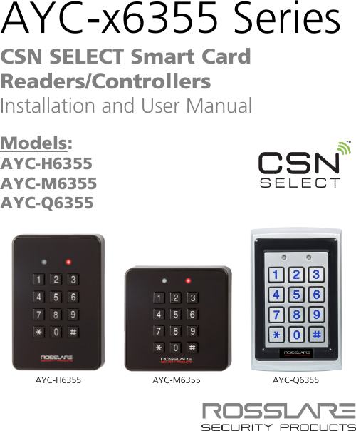
- 1. User Manual Q6355
- 2. User Manual Q6255
User Manual Q6355