Rosslare AYH6X55BT Smart Card Readers User Manual AY H6355BT Installation and
Rosslare Enterprises Ltd Smart Card Readers AY H6355BT Installation and
Rosslare >
User Manual
AY-H6355BT
CSN SMART™ Smart Card
Readers (Rev. A)
Installation and User Manual
BLE 4.1
Copyright © 2017 by Rosslare. All rights reserved.
This manual and the information contained herein are proprietary to ROSSLARE
ENTERPRISES LIMITED and/or its related companies and/or subsidiaries’
(hereafter: "ROSSLARE"). Only ROSSLARE and its customers have the right to
use the information.
No part of this manual may be re-produced or transmitted in any form or by any
means, electronic or mechanical, for any purpose, without the express written
permission of ROSSLARE.
ROSSLARE owns patents and patent applications, trademarks, copyrights, or
other intellectual property rights covering the subject matter in this manual.
TEXTS, IMAGES, AND ILLUSTRATIONS INCLUDING THEIR ARRANGEMENT IN
THIS DOCUMENT ARE SUBJECT TO THE PROTECTION OF COPYRIGHT LAWS
AND OTHER LEGAL RIGHTS WORLDWIDE. THEIR USE, REPRODUCTION, AND
TRANSMITTAL TO THIRD PARTIES WITHOUT EXPRESS WRITTEN PERMISSION
MAY RESULT IN LEGAL PROCEEDINGS.
The furnishing of this manual to any party does not give that party or any third
party any license to these patents, trademarks, copyrights or other intellectual
property rights, except as expressly provided in any written agreement of
ROSSLARE.
ROSSLARE reserves the right to revise and change this document at any time,
without being obliged to announce such revisions or changes beforehand or
after the fact.

Table of Contents
AY-H6355BT Installation and User Manual iii
Table of Contents
1. Introduction ................................................................ 7
1.1 Installation Kit ......................................................................... 8
2. Technical Specifications .............................................. 9
3. Mounting ................................................................... 10
4. Wiring Instructions ................................................... 12
5. OSDP Operation ......................................................... 14
6. Reader Functionality ................................................. 17
6.1 Standby Mode ...................................................................... 17
6.2 Programming ........................................................................ 17
6.2.1 Entering Programming Mode ........................................................ 19
6.2.2 Exiting Programming Mode .......................................................... 19
6.2.3 Selecting Keypad Transmission Format ......................................... 20
6.2.4 Selecting Proximity Card Transmission Format .............................. 25
6.2.5 Changing the Programming Code ................................................ 29
6.2.6 Changing the Facility Code ........................................................... 30
6.2.7 Selecting Credential Technology ................................................... 30
6.2.8 Setting the Backlight Behavior ...................................................... 31
6.2.9 Return to Factory Default Settings ................................................ 32
6.2.10 Replacing a Lost Programming Code ............................................ 32
A. Declaration of Conformity........................................ 33
B. Limited Warranty ...................................................... 34

List of Figures
iv AY-H6355BT Installation and User Manual
List of Figures
Figure 1: Removing the Top Cover .................................................................. 10
Figure 2: DIP Switch Compartment .................................................................. 15
Figure 3: DIP Switch Settings ........................................................................... 16

List of Tables
AY-H6355BT Installation and User Manual v
List of Tables
Table 1: Wiring the Unit as a Reader to a Control Panel .................................. 12
Table 2: Reader Programming Menus .............................................................. 18
Table 3: Keypad Transmission Format Option Number .................................... 21
Table 4: Proximity Card Transmission Format Option Number ......................... 26

Introduction
vi AY-H6355BT Installation and User Manual
Notice and Disclaimer
This manual’s sole purpose is to assist installers and/or users in the safe and
efficient installation and usage of the system and/or product, and/or software
described herein.
BEFORE ATTEMPTING TO INSTALL AND/OR USE THE SYSTEM, THE INSTALLER AND THE
USER MUST READ THIS MANUAL AND BECOME FAMILIAR WITH ALL SAFETY
REQUIREMENTS AND OPERATING PROCEDURES.
The system must not be used for purposes other than those for which it
was designed.
The use of the software associated with the system and/or product, if
applicable, is subject to the terms of the license provided as part of the
purchase documents.
ROSSLARE exclusive warranty and liability is limited to the warranty and
liability statement provided in an appendix at the end of this document.
This manual describes the maximum configuration of the system with the
maximum number of functions, including future options. Therefore, not all
functions described in this manual may be available in the specific system
and/or product configuration you purchased.
Incorrect operation or installation, or failure of the user to effectively
maintain the system, relieves the manufacturer (and seller) from all or any
responsibility for consequent noncompliance, damage, or injury.
The text, images and graphics contained in the manual are for the purpose
of illustration and reference only.
All data contained herein subject to change without prior notice.
In no event shall manufacturer be liable for any special, direct, indirect,
incidental, consequential, exemplary or punitive damages (including,
without limitation, any and all damages from business interruption, loss of
profits or revenue, cost of capital or loss of use of any property or capital or
injury).
All graphics in this manual are for reference only, some deviation between
the image(s) and the actual product may occur.
All wiring diagrams are intended for reference only, the photograph or
graphic of the PCB(s) are intended for clearer illustration and
understanding of the product and may differ from the actual PCB(s).

Introduction
AY-H6355BT Installation and User Manual 7
1. Introduction
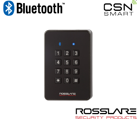
The CSN SMART™ AY-H6355BT is an innovative reader from Rosslare
geared for quad-play operation: backlit PIN keypad, smart card CSN
(13.56 MHz) card reader, NFC-ID read, and BLE-ID smartphone ID
read capabilities. Designed with premium components and IP65
mechanicals, it works well indoors and outdoors. The reader also
features OSDP support and configuration card operation
programming.
The following list shows the credential technologies for which we
have confirmed compatibility:
ISO14443A – MIFARE® Ultralight® Nano / EV1/ C, MIFARE
Classic® / Classic EV1, MIFARE Plus® S / SE / X / EV1, MIFARE
DESFire® EV1 / EV2, N-TAG NFC / Card Emulation
ISO14443B - China National ID
ISO15693 – HID® iClass®, PicoPass, iCode, LEGIC
ISO18092 – SONY® FeliCa® (Hong Kong Octopus)
Rosslare’s CS-ECA NFC app (HCE) for Android smartphones
Scan the QR code to download Rosslare’s NFC app.
Android app and BLE-ID for Android and iPhone
This list is continuously updated, for the latest compatibility list
contact your sales representative.
The standard reader outputs the Wiegand CSN data in Wiegand
26-Bit format. Other Wiegand formats are selectable using the
CS-CCT Configuration Card Tool for the DR-6255
application.

Introduction
8 AY-H6355BT Installation and User Manual
1.1 Installation Kit
The installation kit consists of the following items to be used during
the installation procedure:
1 self-adhesive mounting label template
2 mounting screws and 2 screw anchors
1 Torx key tool
1 Torx security screw

Technical Specifications
AY-H6355BT Installation and User Manual 9
2. Technical Specifications
Electrical Characteristics
Power Supply Type Regulated
Operating Voltage Range 8 to 16 VDC
Current @ 12 V Standby: 120 mA, max: 220 mA
Read Range* Contactless 13.56 MHz and NFC: Up to 7 cm
(2.8 in.)
Bluetooth BLE 4.1: Up to 10 m ( 32 ft) open air
Green LED Control Dry Contact, N.O.
Red LED Control Dry Contact, N.O.
Buzzer Control Dry Contact, N.O.
Tamper Output Open collector, active low, max. sink current
16 mA
Maximum Cable Distance
to Controller
Wiegand: 150 m (500 ft) with 18-AWG cable
OSDP (RS-485): 1,200 m (4,000 ft) with 2x2 18-
AWG twisted shielded cable
Environmental Characteristics
Operating Temp. Range -35°C to 66°C (-31°F to 150°F)
Operating Humidity
Range
0 to 95% (non-condensing)
Outdoor Usage Weather-resistant, UV-resistant, epoxy-potted,
suitable for indoor and outdoor use
* Measured using a Rosslare MIFARE Classic EV1 (ISO card). Read range with
other credential technologies may vary. Range also depends on electrical
environment and proximity to metal.
Physical Characteristics
Dimensions (H x W x D) 110.7 × 75.0 × 18.2 mm (4.4 x 3.0 x 0.7 in.)
Weight 190 g (6.7 oz)
Mounting
10 AY-H6355BT Installation and User Manual
3. Mounting
Before mounting, you should determine the best location for the
reader.
To mount the units:
1. Peel off the back of the self-adhesive mounting label template
and place it at the required mounting location.
2. Using the template as a guide, drill two holes (sizes indicated on
the template) used for mounting the back plate onto the surface.
3. Insert a suitable wall plug into each screw hole.
4. Drill a 10-mm (7/16”) hole for the cable. If mounting on metal,
place a grommet or electrical tape around the edge of the hole.
5. Wire the reader as described in Chapter 4. A linear type power
supply is recommended.
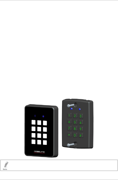
6. Remove the reader's snap-off front cover to reveal the two screw
holes (see Figure 1).
Figure 1: Removing the Top Cover
The location of the screws varies depending on the model
number of the reader.

Mounting
AY-H6355BT Installation and User Manual 11
7. Align the two holes of the reader with those drilled in the wall
and firmly attach the reader to the wall with two screws, whose
size is indicated on the template.
8. Relocate the front cover onto the reader.
The reader can also be mounted using strong epoxy glue. After
application, the reader should be firmly held in place until the
glue dries

Wiring Instructions
12 AY-H6355BT Installation and User Manual
4. Wiring Instructions
The units are supplied with a 10-conductor 5-m (16-ft) pigtail with
exposed wires coated with solder.
To connect the unit as a reader to an access control unit:
1. Select the appropriate connections according to Table 1.
2. Prepare the controller cable by cutting its jacket back about 3 cm
(1¼") and strip the insulation from the wires about 1.3 cm (½").
3. Splice the reader’s pigtail wires to the corresponding controller
wires and cover each joint with insulating tape.
Table 1: Wiring the Unit as a Reader to a Control Panel
Wire Color Output
Red Power
Black Ground
Green Data 0 / Data / C2
White Data 1 / Clock / C1
Orange Green LED Control*
Brown Yellow LED Control*
Purple Tamper Output
Yellow Buzzer Control*
Blue RS-485 - A / OSDP**
Gray RS-485 - B / OSDP**
* These wires have programmable functions that may be adjusted by
presenting a configuration card within 10 seconds upon powering on the
unit. See the
CS-CCT Configuration Card Tool for the DR-6255 Software
Manual
for how you can create a configuration card.
** RS-485 is used for firmware update.

Wiring Instructions
AY-H6355BT Installation and User Manual 13
4. Trim and insulate the ends of all unused conductors individually.
Do not short any unused wires together.
• The individual wires from the reader are color coded according the
Wiegand standard.
• When using a separate power supply for the reader, this supply and
that of the controller must have a common ground.
• The reader’s cable shield wire should be preferably attached to an
earth ground, or a signal ground connection at the panel, or the
power supply end of the cable. This configuration is best for shielding
the reader cable from external interference.

OSDP Operation
14 AY-H6355BT Installation and User Manual
5. OSDP Operation
• In OSDP mode, all control lines (Inputs/Outputs) are disabled.
• In OSDP mode, if a connection is not established or lost with the
controller, the right LED flashes yellow continuously.
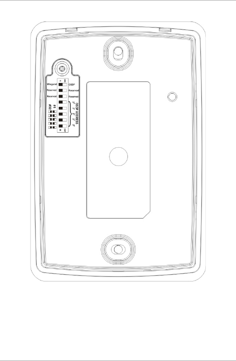
The reader is compatible with all reader-related OSDP commands. The
reader address is set using DIP switches on the back of the reader.
Release the screw on the back of the reader to remove the door to
access the DIP switches (Figure 2).
OSDP Operation
AY-H6355BT Installation and User Manual 15
Figure 2: DIP Switch Compartment
OSDP Operation
16 AY-H6355BT Installation and User Manual
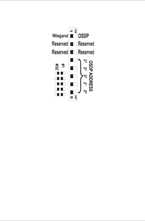
Figure 3 shows the DIP switch settings, which are also described
below.
Figure 3: DIP Switch Settings
DIP Switch 1
This switch is used to select the reader output (Wiegand or OSDP):
Off = Wiegand
On = OSDP
DIP Switch 2
This switch is reserved for future use.
DIP Switch 3
This switch is reserved for future use.
DIP Switches 4 to 8
These switches set the address of the reader for OSDP protocol.
DIP Switch 4 is MSB and DIP Switch 8 is LSB. The address is the DIP
switch state +1.
Examples:
All the DIP switches in Off position, address = 1
All the DIP switches in On position, address = 32

Reader Functionality
AY-H6355BT Installation and User Manual 17
6. Reader Functionality
Upon power on, the unit flashes yellow, then blue, and then orange,
each for 1 second and a beep is heard for each color.
6.1 Standby Mode
The default mode of the reader is Standby mode. In Standby mode,
the unit is ready to receive data from an entered PIN code or from a
presented proximity card, NFC-ID, and BLE-ID.
When the reader is in Standby mode, both LEDs
are blue.
When a contactless card or an NFC-ID device is
presented or a keypad entry is being transmitted,
the right LED flashes green and you hear a beep.
When a BLE-ID device or smartphone app is
received by the reader, the right LED flashes yellow
and you hear two short beeps.
Keypad data can be sent via one of eight different keypad
transmission formats (see Section 6.2.3).
Proximity cards presented to the reader are sent in either various
Wiegand formats or Clock & Data format (see Section 6.2.4).
6.2 Programming
Programming is done solely via the unit's keypad driven Programming
Menu System. During the manufacturing process, certain codes and
settings are pre-programmed. These settings are called the default
factory settings.
Table 2 shows the names of all the reader menus.
Default factory settings are marked by a "*" sign.
blue blue
green blue
yellow
blue

Reader Functionality
18 AY-H6355BT Installation and User Manual
Table 2: Reader Programming Menus
Menu Description Default
1 Selecting Keypad Transmission Format
Single Key, 6-Bit Wiegand (Rosslare Format)
Single Key, 6-Bit Wiegand with Nibble + Parity Bits
Single Key, 8-Bit Wiegand, Nibbles Complemented
4 Keys Binary + Facility Code, Wiegand 26-Bit
1 to 5 Keys + Facility Code, Wiegand 26-Bit
6 Keys BCD and Parity Bits, Wiegand 26-Bit
1 to 8 Keys BCD, Clock & Data
Single Key, Wiegand 4-Bit
*
2 Selecting Card Transmission Format
Wiegand 26-Bit
Clock & Data
Wiegand 32-Bit
Wiegand 32-Bit Reversed Byte
Wiegand 34-Bit
Wiegand 40-Bit
Wiegand 56-Bit
Wiegand 64-Bit
*
3 Changing the Programming Code 1234
4 Changing the Facility Code 0
5 Selecting Credential Technology 0
6 Backlight Options
Off
On (Default)
Off until key press when on for 10 seconds
Dimmed until key press when on for 10 seconds
*
0 Return to Factory Default Settings
Reader Functionality
AY-H6355BT Installation and User Manual 19
6.2.1 Entering Programming Mode
To reach the Programming Menu System, the unit must first be
placed into Programming mode.
• The factory 4-digit Programming code is 1234.
• If a Programming code is not entered within 20 seconds, the unit
returns to Standby mode.
To enter Programming mode:
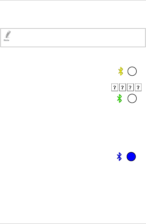
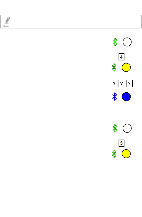
1. Press # four times.
The left LED turns yellow and the right LED
turns off.
2. Enter your 4-digit Programming code.
If the Programming code is valid, the left LED
turns green.
If the Programming code is invalid, you hear a long beep and the
reader returns to Standby mode.
6.2.2 Exiting Programming Mode
To exit Programming mode:
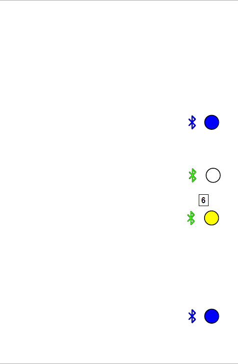
1. Press # to exit Programming mode at any time.
You hear a beep.
Both LEDs are blue.
This indicates that the unit has returned to Standby mode.
Wrong entries may reset the reader back to Standby mode. If no
key is pressed for 20 seconds while in Programming mode, the
unit exits Programming mode and returns to Standby mode.
yellow
green
blue blue
Reader Functionality
20 AY-H6355BT Installation and User Manual
6.2.3 Selecting Keypad Transmission Format
The AYC-x6355 has nine different keypad transmission formats.
See Table 3 in Section 6.2.3.1 for more information on keypad
transmission formats.
• Only one keypad transmission format can be active at any one
time.
• When using the keypad transmission format "1 to 8 keys BCD,
Clock & Data" (Option 8), an additional input is required to specify
the number of keys in the PIN code.
To select the keypad transmission format:
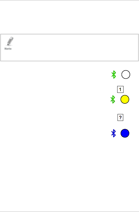
1. Enter Programming mode.
2. Press 1 to enter Menu 1.
The right LED turns yellow.
3. Enter the appropriate option number for the
keypad transmission format that you wish to
select.
You hear three beeps.
The system returns to Standby mode.
If an incorrect option number is entered, the reader returns to
Standby mode and the keypad transmission format remains
unchanged.
green
yellow green
blue blue

Reader Functionality
AY-H6355BT Installation and User Manual 21
6.2.3.1 Keypad Transmission Format Option Number
Table 3 presents the eight different keypad transmission formats.
Table 3: Keypad Transmission Format Option Number
Keypad Transmission Format Option Number
Single Key, Wiegand 6-Bit (Rosslare Format) 1*
Single Key, Wiegand 6-Bit with Nibble + Parity Bits 2
Single Key, Wiegand 8-Bit, Nibbles Complemented 3
4 Keys Binary + Facility Code, Wiegand 26-Bit 4
1 to 5 Keys + Facility Code, Wiegand 26-Bit 5
6 Keys BCD and Parity Bits, Wiegand 26-Bit 6
1 to 8 Keys BCD, Clock & Data Single Key 8
Single Key, Wiegand 4-Bit 9
* Option 1 is the default factory setting.
More information on each of the different keypad transmission
formats is available below and on the following pages.
Option 1: Single Key, Wiegand 6-Bit (Rosslare Format)
Each key press immediately sends 4 bits with 2 parity bits added –
even parity for the first 3 bits and odd parity for the last 3 bits.
0 = 1 1010 0 ="A" in Hexadecimal 6 = 1 0110 0
1 = 0 0001 0 7 = 1 0111 1
2 = 0 0010 0 8 = 1 1000 1
3 = 0 0011 1 9 = 1 1001 0
4 = 1 0100 1 * = 1 1011 1 ="B" in Hexadecimal
5 = 1 0101 0 # = 0 1100 1 ="C" in Hexadecimal

Reader Functionality
22 AY-H6355BT Installation and User Manual
Option 2: Single Key, Wiegand 6-Bit Nibble and Parities
Each key press immediately sends 4 bits with 2 parity bits added –
even parity for the first 3 bits and odd parity for the last 3 bits.
0 = 0 0000 1 6 = 1 0110 0
1 = 0 0001 0 7 = 1 0111 1
2 = 0 0010 0 8 = 1 1000 1
3 = 0 0011 1 9 = 1 1001 0
4 = 1 0100 1 * = 1 1010 0 = "A" in Hexadecimal
5 = 1 0101 0 * = 1 1011 1 = "B" in Hexadecimal
Option 3: Single Key, Wiegand 8-Bit Nibbles Complemented
This option inverts the most significant bits in the message leaving the
least 4 significant bits as a Binary Coded Decimal (BCD) representation
of the key. The host system receives an 8-bit message.
0 = 11110000 6 = 10010110
1 = 11100001 7 = 10000111
2 = 11010010 8 = 01111000
3 = 11000011 9 = 01101001
4 = 10110100 * = 01011010 = "A" in Hexadecimal
5 = 10100101 # = 01001011 = "B" in Hexadecimal
Option 4: 4 Keys Binary + Facility Code, Wiegand 26-Bit
This option buffers 4 keys and outputs keypad data with a 3-digit
Facility code like a standard 26-Bit card output.
The Facility code is set in Programming Menu number four and can be
in the range 000 to 255. The factory default setting for the Facility
code is 000 (see Section 6.2.6).
The keypad PIN code is 4-digit long and can range between 0000 and
9999. On the fourth key press of the 4-digit PIN code, the data is sent
across the Wiegand Data lines as binary data in the same format as a
26-Bit Card.
If * or # are pressed are pressed during PIN code entry, the keypad
clears the PIN code entry buffer, generate a beep and is ready to
receive a new 4-digit keypad PIN code.

Reader Functionality
AY-H6355BT Installation and User Manual 23
If the entry of the 4-digit keypad PIN code is disrupted and no number
key is pressed within 5 seconds, the keypad clears the PIN code entry
buffer, generates a beep and is ready to receive a new 4-digit keypad
PIN code.
(EP) FFFF FFFF AAAA AAAA AAAA AAAA (OP)
Where:
EP = Even parity for first 12 bits
OP = Odd parity for last 12 bits
F = 8-bit Facility code
A = 16-bit code generated from keypad
Option 5: 1 to 5 Keys + Facility Code, Wiegand 26-Bit
Option 5 buffers up to 5 keys and outputs keypad data with a Facility
code like a 26-Bit card output.
The Facility code is set in Programming Menu number four and can be
in the range 000 to 255. The factory default setting for the Facility
code is 000 (see Section 6.2.6).
The keypad PIN code can be one to five digits in length and can range
between 1 and 65,535. When entering a keypad PIN code that is less
than 5 digits in length, # must be pressed to signify the end of PIN
code entry. For keypad PIN codes that are 5 digits in length, on the
fifth key press of the 5-digit PIN code, the data is sent across the
Wiegand Data lines as binary data in the same format as a 26-Bit
Card.
If * is pressed during PIN code entry or a PIN code greater than
65,535 is entered, the keypad clears the PIN code entry buffer,
generates a beep and is ready to receive a new 5-digit keypad PIN
code.
If the entry of the 1- to 5-digit keypad PIN code is disrupted and a
number key or # is not pressed within 5 seconds, the keypad clears
the PIN code entry buffer, generates a medium length beep and is
ready to receive a new 1- to 5-digit keypad PIN code.

Reader Functionality
24 AY-H6355BT Installation and User Manual
(EP) FFFF FFFF AAAA AAAA AAAA AAAA (OP)
Where:
EP = Even parity for first 12 bits
OP = Odd parity for last 12 bits
F = 8-bit Facility code
A = 16-bit code generated from keypad
Option 6: 6 Keys BCD and Parity Bits, Wiegand 26-Bit
Option 6 sends buffer of 6 keys, adds parity and sends a 26-Bit Binary
BCD message. Each key is a four bit equivalent of the decimal
number.
The keypad PIN code must be 6 key presses long. On the sixth key
press of the 6-digit PIN code, the data is sent across the Wiegand
Data lines as a BCD message.
If the entry of the 6-digit keypad PIN code is disrupted and no number
key is pressed within 5 seconds, the keypad clears the PIN code entry
buffer, generates a medium length beep and is ready to receive a new
6-digit keypad PIN code.
(EP) AAAA BBBB CCCC DDDD EEEE FFFF (OP)
Where:
EP = Even parity for first 12 bits
OP = Odd parity for last 12 bits
A = The first key entered D = Fourth key entered
B = Second key entered E = Fifth key entered
C = Third key entered F = Sixth key entered
Option 8: 1 to 8 Keys BCD, Clock & Data
Buffers up to 8 keys and outputs keypad data without a Facility code
like standard Clock and Data card output.
The keypad PIN code can be one to eight digits in length. The PIN
code length is selected while programming the reader for Option 8.
The reader transmits the data when it receives the last key press of
Reader Functionality
AY-H6355BT Installation and User Manual 25
the PIN code. The data is sent across the two data output lines as
binary data in Clock & Data format.
If * or # key is pressed during PIN code entry, the keypad clears the
PIN code entry buffer, generates a beep, and is ready to receive a new
keypad PIN code.
If the entry of the digit keypad PIN code is disrupted and a number
key or # is not pressed within 5 seconds, the keypad clears the PIN
code entry buffer, generates a medium length beep, and is ready to
receive a new keypad PIN code.
When using the keypad transmission format "1 to 8 keys BCD,
Clock & Data" (Option 8) an additional input is required to
specify the number of keys in the PIN code.
Option 9: Single Key, Wiegand 4-Bit
Each key press immediately sends 4 bits of data, with no parity bits
added.
0 = 0000 6 = 0110
1 = 0001 7 = 0111
2 = 0010 8 = 1000
3 = 0011 9 = 1001
4 = 0100 * = 1010 ="A" in Hexadecimal
5 = 0101 # =1011 ="B" in Hexadecimal
6.2.4 Selecting Proximity Card Transmission Format
There are eight different proximity card transmission formats.
See Table 3 in Section 6.2.3.1 for more information on keypad
transmission formats.
To select the proximity card transmission format:
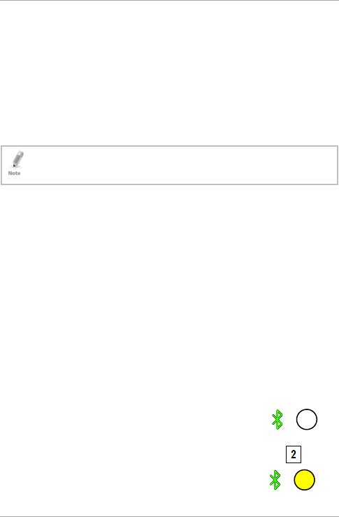
1. Enter Programming mode.
2. Press 2 to enter Menu 2.
The right LED turns yellow.
green
yellow green

Reader Functionality
26 AY-H6355BT Installation and User Manual
3. Enter the appropriate option number for the proxy card
transmission format that you wish to select:
1 – Wiegand 26-Bit
2 – Clock & Data
3 – Wiegand 32-Bit
4 – Wiegand 32-Bit Reversed Byte
5 – Wiegand 34-Bit
6 – Wiegand 40-Bit
7 – Wiegand 56-Bit
8 – Wiegand 64-Bit
You hear three beeps.
The system returns to Standby mode.
6.2.4.1 Proximity Card Transmission Format Option Number
Table 4 presents the nine different keypad transmission formats.
Table 4: Proximity Card Transmission Format Option Number
Proximity Card Transmission Format Option Number
Wiegand 26-Bit 1*
Clock & Data 2
Wiegand 32-Bit 3
Wiegand 32-Bit Reversed Byte 4
Wiegand 34-Bit 5
Wiegand 40-Bit 6
Wiegand 56-Bit 7
Wiegand 64-Bit 8
* Option 1 is the default factory setting.
More information on each of the different keypad transmission
formats is available below and on the following pages.
blue blue

Reader Functionality
AY-H6355BT Installation and User Manual 27
Option 1: Wiegand 26-Bit
In this mode, 3 LSB bytes from the card serial number (UID) are
transmitted in Wiegand 26-Bit format. Two parity bits are added. An
even parity bit is sent first, followed by three bytes of card data, and
by an odd parity bit.
(EP) AAAA AAAA AAAA AAAA AAAA AAAA (OP)
Where: EP = Even parity for first 12 bits
OP = Odd parity for last 12 bits
A = 3 bytes code generated from card data
Option 2: Clock and Data
In this mode, up to 6 bytes of the card serial number are transmitted
in Clock & Data format.
Option 3: Wiegand 32-Bit
In this mode, 4 LSB bytes from the card serial number are transmitted in
Wiegand 32-Bit format. No parity bits are added.
AAAA AAAA BBBB BBBB CCCC CCCC DDDD DDDD
Where: A = 4th (MSB) byte of card serial number
B = 3rd byte of card serial number
C = 2nd byte of card serial number
D = 1st (LSB) byte of card serial number
Option 4: Wiegand 32-Bit Reversed Byte
In this mode, 4 LSB bytes from card serial number are transmitted in Wiegand
32-bit format. Bytes are sent in reversed order. The LSB part of the card serial
number is sent first and the MSB byte is sent last. No parity bits are added.
DDDD DDDD BBBB BBBB CCCC CCCC AAAA AAAA

Reader Functionality
28 AY-H6355BT Installation and User Manual
Where: D = 1st (LSB) byte of card serial number
C = 2nd byte of card serial number
B = 3rd byte of card serial number
A = 4th (MSB) byte of card serial number
Option 5: Wiegand 34-Bit
In this mode, 4 LSB bytes of card serial number are transmitted in
Wiegand 34-Bit format. Bytes are sent in reversed order. The LSB part
of the card serial number is sent first and the MSB byte is sent last. An
even parity is sent first, followed by 32-Bit data and an odd parity bit.
(EP) AAAA AAAA BBBB BBBB CCCC CCCC DDDD DDDD (OP)
Where: EP = Even parity for first 16 data bits
OP = Odd parity for last 16 data bits
A = 4th (MSB) byte of card serial number
B = 3rd byte of card serial number
C = 2nd byte of card serial number
D = 1st (LSB) byte of card serial number
Option 6: Wiegand 40-Bit
In this mode, 4 LSB bytes of card serial number are transmitted in
Wiegand 40-Bit format. Bytes are sent in reversed order. The LSB part
of card serial number is sent first. The last byte sent is a Checksum
byte generated by adding 4 data bytes and discarding the remainder
beyond 8 bytes.
AAAA AAAA BBBB BBBB CCCC CCCC DDDD DDDD (CSUM)
Where: A = 4th (MSB) byte of card serial number
B = 3rd byte of card serial number
C = 2nd byte of card serial number
D = 1st (LSB) byte of card serial number
CSUM = Checksum value, 1 byte (A+B+C+D)
Reader Functionality
AY-H6355BT Installation and User Manual 29
Option 7: Wiegand 56-Bit
In this mode, 7 bytes of card serial number are transmitted in
Wiegand 56-Bit format. No parity bits are added.
AAAA AAAA BBBBBBBB CCCCCCCC DDDDDDDD EEEEEEEE
FFFFFFFF GGGGGGGG
Option 8: Wiegand 64-Bit
In this mode, 8 bytes of card serial number are transmitted in
Wiegand 64-Bit format. No parity bits are added.
AAAA AAAA BBBBBBBB CCCCCCCC DDDDDDDD EEEEEEEE
FFFFFFFF GGGGGGGG HHHHHHHH
6.2.5 Changing the Programming Code
• The Programming code cannot be erased, meaning the code 0000
is invalid and does not erase the Programming code.
• The factory default 4-digit Programming code is 1234.
To change the Programming code:
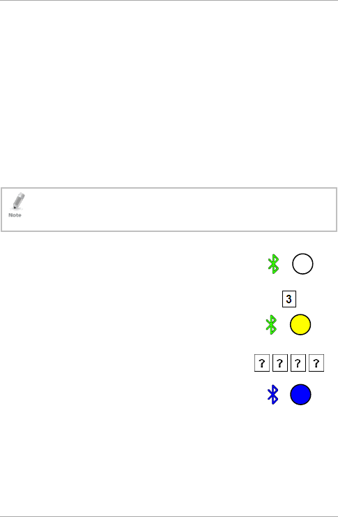
1. Enter Programming mode.
2. Press 3 to enter Menu 3.
The right LED turns yellow.
3. Enter the new 4-digit code you wish to set as
the Programming code.
You hear three beeps.
The system returns to Standby mode.
green
yellow green
blue blue
Reader Functionality
30 AY-H6355BT Installation and User Manual
6.2.6 Changing the Facility Code
• The Facility code can be in the range of 000 to 255.
• The default Facility code is 0.
To change the Facility code:
1. Enter Programming mode.
2. Press 4 to enter Menu 4.
The right LED turns yellow.
3. Enter the new 3-digit code you wish to set as
the Facility code.
You hear three beeps.
The system returns to Standby mode.
6.2.7 Selecting Credential Technology
To select the credential technology:
1. Enter Programming mode.
2. Press 5 to enter Menu 5.
The right LED turns yellow.
green
yellow green
blue blue
green
yellow green
Reader Functionality
AY-H6355BT Installation and User Manual 31
3. Enter one of the following codes:
0 – All formats (default)
1 – 14443A
2 – 14443B
3 – 15693
4 – Felica
5 – China ID
6 – Topaz
You hear three beeps.
The system returns to Standby mode.
6.2.8 Setting the Backlight Behavior
To set the backlight behavior:
1. Enter Programming mode.
2. Press 6 to enter Menu 6.
The right LED turns yellow.
3. Enter one of the following codes:
0 for always off
1 for always on
2 for 10 sec. backlight after a key is pressed otherwise off
3 for 10 sec. backlight after a key is pressed otherwise
dimmed
You hear three beeps.
The system returns to Standby mode.
blue blue
green
yellow green
blue blue
Reader Functionality
32 AY-H6355BT Installation and User Manual
6.2.9 Return to Factory Default Settings
You must be very careful before using this command! This
erases the entire memory and return all codes to their factory
default setting.
To return to factory default settings:
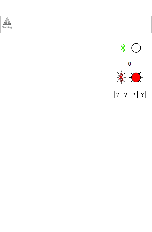
1. Enter Programming mode.
2. Press 0 to enter Menu 0.
Both LEDs flash red.
3. Enter your 4-digit Programming code.
If the Programming code is valid, all memory is erased. You hear
three beeps and the reader returns to Standby mode.
If the Programming code is invalid, you hear a long beep and the
reader returns to Standby mode without erasing the memory of
the reader.
6.2.10 Replacing a Lost Programming Code
In the event that the Programming code is forgotten, the AYC-x6355
can be reprogrammed in the field using the following instructions:
1. Remove power from the reader.
2. Activate tamper by removing the reader from the wall or
removing the reader's case.
3. Apply power to the reader.
4. You now have 10 seconds to enter Programming mode using the
factory default Programming code 1234.
green
red
red

Declaration of Conformity
AY-H6355BT Installation and User Manual 33
A. Declaration of Conformity
This device complies with Part 15 of the FCC Rules. Operation is
subject to the following two conditions:
This device may not cause harmful interference.
This device must accept any interference received, including
interference that may cause undesired operation.
Changes or modifications not expressly approved by the party
responsible for compliance could void the user's authority to operate
the equipment.
This equipment has been tested and found to comply with the limits
for a Class B digital device, pursuant to part 15 of the FCC Rules.
These limits are designed to provide reasonable protection against
harmful interference in a residential installation.
This equipment generates, uses, and can radiate radio frequency
energy and, if not installed and used in accordance with the
instructions, may cause harmful interference to radio
communications. However, there is no guarantee that interference
will not occur in a particular installation. If this equipment does cause
harmful interference to radio or television reception, which can be
determined by turning the equipment off and on, the user is
encouraged to try to correct the interference by one or more of the
following measures:
Reorient or relocate the receiving antenna.
Increase the separation between the equipment and receiver.
Connect the equipment into an outlet on a circuit different from
that to which the receiver is connected.
Consult the dealer or an experienced radio/TV technician for help.
This equipment should be installed and operated with minimum
distance 20cm between the radiator & your body.

Limited Warranty
34 AY-H6355BT Installation and User Manual
B. Limited Warranty
The full ROSSLARE Limited Warranty Statement is available in the
Quick Links section on the ROSSLARE website at
www.rosslaresecurity.com.
Rosslare considers any use of this product as agreement to the
Warranty Terms even if you do not review them.

AY-H6355BT
0706-0960644+00
Asia Pacific, Middle
East, Africa
Rosslare Enterprises Ltd.
Kowloon Bay, Hong Kong
Tel: +852-2795-5630
Fax: +852-2795-1508
support.apac@rosslaresecurity.com
United States and
Canada
Rosslare Security Products, Inc.
Southlake, TX, USA
Toll Free: +1-866-632-1101
Local: +1-817-305-0006
Fax: +1-817-305-0069
support.na@rosslaresecurity.com
Europe
Rosslare Israel Ltd.
22 Ha'Melacha St., P.O.B. 11407
Rosh HaAyin, Israel
Tel: +972-3-938-6838
Fax: +972-3-938-6830
support.eu@rosslaresecurity.com
Latin America
Rosslare Latin America
Buenos Aires, Argentina
Tel: +54-11-4001-3104
support.la@rosslaresecurity.com
China
Rosslare Electronics (Shenzhen) Ltd.
Shenzhen, China
Tel: +86-755-8610 6842
Fax: +86-755-8610 6101
support.cn@rosslaresecurity.com
India
Rosslare Electronics India Pvt Ltd.
Tel/Fax: +91-20-40147830
Mobile: +91-9975768824
sales.in@rosslaresecurity.com
CERT
ISO 9001
ISO 14001
The N-Mark is a trademark or registered trademark of NFC Forum, Inc. in the United States
and in other countries.